EP2113364A1 - Apparatus and process - Google Patents
Apparatus and process Download PDFInfo
- Publication number
- EP2113364A1 EP2113364A1 EP08103227A EP08103227A EP2113364A1 EP 2113364 A1 EP2113364 A1 EP 2113364A1 EP 08103227 A EP08103227 A EP 08103227A EP 08103227 A EP08103227 A EP 08103227A EP 2113364 A1 EP2113364 A1 EP 2113364A1
- Authority
- EP
- European Patent Office
- Prior art keywords
- polymer
- extruder
- feed
- screw
- barrel
- Prior art date
- Legal status (The legal status is an assumption and is not a legal conclusion. Google has not performed a legal analysis and makes no representation as to the accuracy of the status listed.)
- Withdrawn
Links
Images

Classifications
-
- B—PERFORMING OPERATIONS; TRANSPORTING
- B29—WORKING OF PLASTICS; WORKING OF SUBSTANCES IN A PLASTIC STATE IN GENERAL
- B29C—SHAPING OR JOINING OF PLASTICS; SHAPING OF MATERIAL IN A PLASTIC STATE, NOT OTHERWISE PROVIDED FOR; AFTER-TREATMENT OF THE SHAPED PRODUCTS, e.g. REPAIRING
- B29C48/00—Extrusion moulding, i.e. expressing the moulding material through a die or nozzle which imparts the desired form; Apparatus therefor
- B29C48/25—Component parts, details or accessories; Auxiliary operations
- B29C48/285—Feeding the extrusion material to the extruder
-
- B—PERFORMING OPERATIONS; TRANSPORTING
- B29—WORKING OF PLASTICS; WORKING OF SUBSTANCES IN A PLASTIC STATE IN GENERAL
- B29C—SHAPING OR JOINING OF PLASTICS; SHAPING OF MATERIAL IN A PLASTIC STATE, NOT OTHERWISE PROVIDED FOR; AFTER-TREATMENT OF THE SHAPED PRODUCTS, e.g. REPAIRING
- B29C48/00—Extrusion moulding, i.e. expressing the moulding material through a die or nozzle which imparts the desired form; Apparatus therefor
- B29C48/25—Component parts, details or accessories; Auxiliary operations
- B29C48/36—Means for plasticising or homogenising the moulding material or forcing it through the nozzle or die
- B29C48/395—Means for plasticising or homogenising the moulding material or forcing it through the nozzle or die using screws surrounded by a cooperating barrel, e.g. single screw extruders
- B29C48/397—Means for plasticising or homogenising the moulding material or forcing it through the nozzle or die using screws surrounded by a cooperating barrel, e.g. single screw extruders using a single screw
-
- B—PERFORMING OPERATIONS; TRANSPORTING
- B29—WORKING OF PLASTICS; WORKING OF SUBSTANCES IN A PLASTIC STATE IN GENERAL
- B29C—SHAPING OR JOINING OF PLASTICS; SHAPING OF MATERIAL IN A PLASTIC STATE, NOT OTHERWISE PROVIDED FOR; AFTER-TREATMENT OF THE SHAPED PRODUCTS, e.g. REPAIRING
- B29C48/00—Extrusion moulding, i.e. expressing the moulding material through a die or nozzle which imparts the desired form; Apparatus therefor
- B29C48/25—Component parts, details or accessories; Auxiliary operations
- B29C48/36—Means for plasticising or homogenising the moulding material or forcing it through the nozzle or die
- B29C48/395—Means for plasticising or homogenising the moulding material or forcing it through the nozzle or die using screws surrounded by a cooperating barrel, e.g. single screw extruders
- B29C48/40—Means for plasticising or homogenising the moulding material or forcing it through the nozzle or die using screws surrounded by a cooperating barrel, e.g. single screw extruders using two or more parallel screws or at least two parallel non-intermeshing screws, e.g. twin screw extruders
-
- B—PERFORMING OPERATIONS; TRANSPORTING
- B29—WORKING OF PLASTICS; WORKING OF SUBSTANCES IN A PLASTIC STATE IN GENERAL
- B29C—SHAPING OR JOINING OF PLASTICS; SHAPING OF MATERIAL IN A PLASTIC STATE, NOT OTHERWISE PROVIDED FOR; AFTER-TREATMENT OF THE SHAPED PRODUCTS, e.g. REPAIRING
- B29C48/00—Extrusion moulding, i.e. expressing the moulding material through a die or nozzle which imparts the desired form; Apparatus therefor
- B29C48/25—Component parts, details or accessories; Auxiliary operations
- B29C48/36—Means for plasticising or homogenising the moulding material or forcing it through the nozzle or die
- B29C48/50—Details of extruders
- B29C48/68—Barrels or cylinders
-
- B—PERFORMING OPERATIONS; TRANSPORTING
- B29—WORKING OF PLASTICS; WORKING OF SUBSTANCES IN A PLASTIC STATE IN GENERAL
- B29C—SHAPING OR JOINING OF PLASTICS; SHAPING OF MATERIAL IN A PLASTIC STATE, NOT OTHERWISE PROVIDED FOR; AFTER-TREATMENT OF THE SHAPED PRODUCTS, e.g. REPAIRING
- B29C48/00—Extrusion moulding, i.e. expressing the moulding material through a die or nozzle which imparts the desired form; Apparatus therefor
- B29C48/03—Extrusion moulding, i.e. expressing the moulding material through a die or nozzle which imparts the desired form; Apparatus therefor characterised by the shape of the extruded material at extrusion
-
- B—PERFORMING OPERATIONS; TRANSPORTING
- B29—WORKING OF PLASTICS; WORKING OF SUBSTANCES IN A PLASTIC STATE IN GENERAL
- B29C—SHAPING OR JOINING OF PLASTICS; SHAPING OF MATERIAL IN A PLASTIC STATE, NOT OTHERWISE PROVIDED FOR; AFTER-TREATMENT OF THE SHAPED PRODUCTS, e.g. REPAIRING
- B29C48/00—Extrusion moulding, i.e. expressing the moulding material through a die or nozzle which imparts the desired form; Apparatus therefor
- B29C48/25—Component parts, details or accessories; Auxiliary operations
- B29C48/285—Feeding the extrusion material to the extruder
- B29C48/286—Raw material dosing
-
- B—PERFORMING OPERATIONS; TRANSPORTING
- B29—WORKING OF PLASTICS; WORKING OF SUBSTANCES IN A PLASTIC STATE IN GENERAL
- B29C—SHAPING OR JOINING OF PLASTICS; SHAPING OF MATERIAL IN A PLASTIC STATE, NOT OTHERWISE PROVIDED FOR; AFTER-TREATMENT OF THE SHAPED PRODUCTS, e.g. REPAIRING
- B29C48/00—Extrusion moulding, i.e. expressing the moulding material through a die or nozzle which imparts the desired form; Apparatus therefor
- B29C48/25—Component parts, details or accessories; Auxiliary operations
- B29C48/285—Feeding the extrusion material to the extruder
- B29C48/288—Feeding the extrusion material to the extruder in solid form, e.g. powder or granules
-
- B—PERFORMING OPERATIONS; TRANSPORTING
- B29—WORKING OF PLASTICS; WORKING OF SUBSTANCES IN A PLASTIC STATE IN GENERAL
- B29K—INDEXING SCHEME ASSOCIATED WITH SUBCLASSES B29B, B29C OR B29D, RELATING TO MOULDING MATERIALS OR TO MATERIALS FOR MOULDS, REINFORCEMENTS, FILLERS OR PREFORMED PARTS, e.g. INSERTS
- B29K2101/00—Use of unspecified macromolecular compounds as moulding material
- B29K2101/12—Thermoplastic materials
Definitions
- the present invention relates to an extruder for a polymer, and a process for extruding a polymer using said extruder.
- the extrusion of polymer is a common processing step in polymer production.
- polymer powder is passed by gravity from a feed hopper through what is known as a feed port and into an extruder barrel in which there are one or more rotating screws. The screws rotate to move the polymer away from the feed port along the barrel. Thermal and mechanical energy (from the screw(s)) are provided to the polymer powder in the barrel causing it to melt. Once melted the polymer is passed into a suitable die and extruded to form polymer in the desired extruded form, such as pellets or film.
- Common extruders are single-screw extruders, having, as the name suggests, a single screw, twin-screw extruders and twin rotor mixer extruders. Twin screw and twin rotor mixer extruders have two screws or rotors which may be counter- or co-rotating, and which may be non-intermeshing, partially intermeshing, or fully intermeshing.
- extruders are made up of barrel sections having a "standard" barrel length. Typically the overall length of a standard barrel section is 2 to 3 times the diameter of the screw or rotor.
- polymer is fed into the first barrel section in a sequence, with at least a second barrel section being provided "downstream”.
- At least a third barrel section is also common to ensure polymer is completely melted prior to extrusion.
- parameters which are important in the extrusion process including, for example, barrel dimensions, screw speed, screw pitch and torque.
- the general direction in the art has been to increase extrusion throughput, which has involved increasing all linear dimensions of the barrel, the screw speed and the torque as much as possible since these have, to date, been the limiting factors.
- the principal requirement of the feeding of the polymer has been to sufficiently fill the barrel as the polymer is moved along it.
- the polymer is fed to the first barrel section, usually from a hopper, through an area known as the feed port. It is typical that the feed port width is maximised based on the barrel section width i.e. up to the extremity of the screws, which is either 1 times the diameter of the screw in the case of a single screw extruder, or up to 2 times the diameter of the screws or rotors in the case of twin screw or twin rotor extruders.
- the feed port also has an axial length of up to 2 times the diameter of the screw or rotor in this section of the extruder, giving a feed port area with length and width both up to 2 times the screw diameter.
- an extruder comprising:
- the extruder comprises three of more barrel sections.
- each barrel section will contain one or more screw sections in communication with the one or more screws in the upstream feed barrel section.
- the present invention is characterised in that the total length of the one or more feed ports through which polymer feedstock is introduced is greater than 2*X, where X is the diameter of the one or more screws in the upstream feed barrel section.
- screw and rotor are widely used in the extruder industry, often apparently interchangeably. As used herein the term “screw” is meant to include both such screws and rotors.
- the object of the present invention may be achieved by adding a second feed port downstream of the first feed port, or even multiple feed ports downstream of the first feed port, such that the combined length of the two ports is greater than 2*X.
- a single feed port is used which has a length of greater than 2*X.
- the total length of the one or more feed ports through which polymer is introduced is greater than 2.5*X, and most preferably greater than 3*X.
- the length of the feed port may be greater than the length of a so-called "standard" barrel.
- the length of the feed port may extend the feed port onto a second downstream barrel section such that at least part of it feeds polymer directly into the second barrel section.
- the extruder may comprise three of more barrel sections each having a length, L, and the feed port has a length of greater than L.
- the feed port area will generally be a rectangular shape with width limited by the width of the upstream feed barrel section i.e. either 1*X in the case of a single screw extruder, or 2*X in the case of twin screw or twin rotor extruders.
- the rectangular shape is preferably a rectangle with rounded corners, since angled corners are more prone to powder sticking therein.
- the feed port area will preferably be greater than 2*X 2 , more preferably greater than 2.S*X 2 and most preferably greater than 3*X 2 , whereas for a twin screw extruder the feed port area will preferably be greater than 4*X 2 , more preferably greater than 5*X 2 and most preferably greater than 6*X 2
- the screw pitch is the distance between the adjacent points at which the screw helix returns to the same radial position on the screw.
- the screw pitch as used herein is the distance where an individual screw helix returns to the same radial position, which will be greater than the distance between adjacent helixes.
- the pitch is also shown schematically in Figure 2 .
- the ratio of screw pitch to screw diameter within the upstream feed barrel section is suitably at least 1 and no greater than 2.5.
- the present invention provides a process for extrusion of polymer comprising feeding a polymer feedstock to the feed port of an extruder as described herein.
- the polymer feedstock is typically provided in the form of powder or pellets.
- the polymer feedstock of the present invention is preferably a polymer of ethylene or propylene, either homopolymers thereof or copolymers thereof with another comonomer.
- the present invention applies particularly to relatively high capacity extrusion processes and relatively large extruder dimensions.
- extruders which may be single screw extruders, twin screw extruders, or twin rotor extruders, with screw diameter(s) of 200 mm or greater in the upstream feed barrel section.
- the extruder and process of the present invention may be used with any polymer powder, even those that are generally considered as “free-flowing” or “easy-flowing", the present invention applies particularly to polymer powders with relatively poor flow properties.
- Powder flow properties are typically characterised by testing in a shear cell.
- An example of such a test is described in ASTM D 6773-02 "Standard Shear Test Method for Bulk Solids Using the Schulze Ring Shear Tester".
- ASTM D 6773-02 the flow function of a polymer powder is a plot of the unconfined yield strength of the powder versus major consolidation stress.
- polymers are rated in their flowability in terms of the flowability ratio, ff c , which is defined as the ratio of the consolidation stress to the unconfined yield strength, as follows: ff c ⁇ 1 non - flowing 1 ⁇ ff c ⁇ 2 very cohesive to non - flowing 2 ⁇ ff c ⁇ 4 cohesive 4 ⁇ ff c ⁇ 10 easy - flowing 10 ⁇ ff c free - flowing .
- ff c the flowability ratio
- the present invention is particularly applicable to polymer powders with a value of ffc less than 4, although it may also be useful even for polymer powders with values above 4.
- the polymer powder to be extruded in the process of the present invention has a flowability ratio of less than 6. More preferably, the polymer powder to be extruded in the process of the present invention has a flowability ratio of less than 4, and most preferably has a flowability ratio of less than 2. Preferably, the polymer powder to be extruded in the process of the present invention has a flowability ratio of at least 1. It should be noted that the flowability ratio of a polymer powder may change as a function of the consolidation pressure and also of temperature.
- the flowability ratio of the polymer powder is the value measured using the instantaneous shear test described in ASTM D 6773-02 at a consolidation pressure of 2000 Pa and at a temperature that is equal to the temperature of the polymer powder at the feed port during the extrusion process to which it is to be fed.
- the flowability ratio of the polyethylene powder should be measured at a temperature of 65°C.
- FIG. 1 An extruder according to the present invention is shown schematically in Figure 1 .
- Figure 1 shows an extruder having three barrel sections, denoted 1a (upstream feed barrel section), 1b (second barrel section) and 1c (downstream barrel section), each having a length, L.
- the barrels contain a screw of diameter X (not shown).
- the internal height of each barrel is a fraction greater than X necessary to contain the screw and allow the rotation of the screw during operation).
- the length L is approximately 2.5*X.
- To feed polymer into the extruder there is provided a hopper, 2, with a feed port the axial length, Z, which is at least 2*X (approximately 3*X as shown).
- Figure 2 shows in schematic form a section of a single screw of an extruder, showing the screw pitch, P, and the diameter, X.
- Figure 3 shows in schematic form a top view of a section of twin-screws of a twin screw extruder. In this case the width is 2*X.
Abstract
The present invention relates to an extruder for a polymer, and a process for extruding a polymer using said extruder, said extruder comprising:
(i) two or more barrel sections (1a,1b,1c) arranged sequentially from:
(a) an upstream feed barrel section (1a) to which polymer feedstock to be extruded is fed, the upstream feed barrel section containing one or more screws each having a diameter of X; to
(b) a downstream barrel section (1c) from which melted polymer is passed to a die and extruded; and
(ii) one or more feed ports for feeding polymer feedstock to be extruded into the extruder at its upstream end,
characterised in that the total length of the one or more feed ports through which polymer feedstock is introduced is greater than 2*X.
Description
- The present invention relates to an extruder for a polymer, and a process for extruding a polymer using said extruder.
- The extrusion of polymer is a common processing step in polymer production. In general, polymer powder is passed by gravity from a feed hopper through what is known as a feed port and into an extruder barrel in which there are one or more rotating screws. The screws rotate to move the polymer away from the feed port along the barrel. Thermal and mechanical energy (from the screw(s)) are provided to the polymer powder in the barrel causing it to melt. Once melted the polymer is passed into a suitable die and extruded to form polymer in the desired extruded form, such as pellets or film. Common extruders are single-screw extruders, having, as the name suggests, a single screw, twin-screw extruders and twin rotor mixer extruders. Twin screw and twin rotor mixer extruders have two screws or rotors which may be counter- or co-rotating, and which may be non-intermeshing, partially intermeshing, or fully intermeshing.
- In industrial scale extrusion processes typical extruders are made up of barrel sections having a "standard" barrel length. Typically the overall length of a standard barrel section is 2 to 3 times the diameter of the screw or rotor. Conventionally, at industrial scale polymer is fed into the first barrel section in a sequence, with at least a second barrel section being provided "downstream". At least a third barrel section is also common to ensure polymer is completely melted prior to extrusion. There are a number of parameters which are important in the extrusion process, including, for example, barrel dimensions, screw speed, screw pitch and torque. The general direction in the art has been to increase extrusion throughput, which has involved increasing all linear dimensions of the barrel, the screw speed and the torque as much as possible since these have, to date, been the limiting factors.
- The principal requirement of the feeding of the polymer has been to sufficiently fill the barrel as the polymer is moved along it. The polymer is fed to the first barrel section, usually from a hopper, through an area known as the feed port. It is typical that the feed port width is maximised based on the barrel section width i.e. up to the extremity of the screws, which is either 1 times the diameter of the screw in the case of a single screw extruder, or up to 2 times the diameter of the screws or rotors in the case of twin screw or twin rotor extruders.
- Typically, the feed port also has an axial length of up to 2 times the diameter of the screw or rotor in this section of the extruder, giving a feed port area with length and width both up to 2 times the screw diameter.
- To date the feed port area has not generally been limiting on the process, and therefore has not caused a great deal of concern.
- However, it has now been found that as capacity increases, and even though the feed port area is generally increased (by proportional increases in its width and length) as the screw and barrel sizes are increased, the feed port area increases only in a squared mathematical relationship whereas the throughput increases in a cubic relationship, and there becomes an issue that the polymer does not feed into the barrel through the feed port at a rate fast enough to fill the barrel sufficiently. This issue is especially significant for feedstocks with poor flowability.
- Thus, in order to meet the continued requirements for higher capacity it is necessary to design an extruder which has an increased polymer feed capability compared to prior art extruders.
- Thus, in a first aspect the present invention provides an extruder comprising:
- (i) two or more barrel sections arranged sequentially from:
- (a) an upstream feed barrel section to which polymer feedstock to be extruded is fed, the upstream feed barrel section containing one or more screws each having a diameter of X; to
- (b) a downstream barrel section from which melted polymer is passed to a die and extruded; and
- (ii) one or more feed ports for feeding polymer feedstock to be extruded into the extruder at its upstream end,
- Preferably, the extruder comprises three of more barrel sections.
- For avoidance of doubt, although it is the diameter of the one or more screws in the upstream feed barrel section that is important in the process of the present invention, each barrel section will contain one or more screw sections in communication with the one or more screws in the upstream feed barrel section.
- The present invention is characterised in that the total length of the one or more feed ports through which polymer feedstock is introduced is greater than 2*X, where X is the diameter of the one or more screws in the upstream feed barrel section.
- It is noted that the terms "screw" and "rotor" are widely used in the extruder industry, often apparently interchangeably. As used herein the term "screw" is meant to include both such screws and rotors.
- In one embodiment, the object of the present invention may be achieved by adding a second feed port downstream of the first feed port, or even multiple feed ports downstream of the first feed port, such that the combined length of the two ports is greater than 2*X.
- However, it is generally preferred that a single feed port is used which has a length of greater than 2*X.
- Preferably, the total length of the one or more feed ports through which polymer is introduced is greater than 2.5*X, and most preferably greater than 3*X.
- It will be apparent that, particularly where a single feed port is used, the length of the feed port may be greater than the length of a so-called "standard" barrel.
- It is possible to use an extended or "non-standard" barrel having an increased length for the upstream feed barrel section. Alternatively, the length of the feed port may extend the feed port onto a second downstream barrel section such that at least part of it feeds polymer directly into the second barrel section. For example, the extruder may comprise three of more barrel sections each having a length, L, and the feed port has a length of greater than L.
- Although other shapes may in theory be used, for maximum area per unit length and for simplicity of design and manufacture, the feed port area will generally be a rectangular shape with width limited by the width of the upstream feed barrel section i.e. either 1*X in the case of a single screw extruder, or 2*X in the case of twin screw or twin rotor extruders. The rectangular shape is preferably a rectangle with rounded corners, since angled corners are more prone to powder sticking therein.
- Thus, for a single screw extruder the feed port area will preferably be greater than 2*X2, more preferably greater than 2.S*X2 and most preferably greater than 3*X2, whereas for a twin screw extruder the feed port area will preferably be greater than 4*X2, more preferably greater than 5*X2 and most preferably greater than 6*X2
- Another important parameter in the process of the present invention is the screw pitch. The screw pitch is the distance between the adjacent points at which the screw helix returns to the same radial position on the screw. For avoidance of doubt, where the screw comprises more than one helix, the screw pitch as used herein is the distance where an individual screw helix returns to the same radial position, which will be greater than the distance between adjacent helixes. The pitch is also shown schematically in
Figure 2 . The ratio of screw pitch to screw diameter within the upstream feed barrel section is suitably at least 1 and no greater than 2.5. - The use of a longer screw pitch can increase the extruder throughput. However, without the use of an axially extended feed port according to the process of the present invention it has been found that as scale increases this results in the channels in the screw being only partially filled, so that any further increase in pitch, or an increase in speed, will not give an increase in throughput. In addition in the case of long pitch screws the forward conveying efficiency of the polymer feedstock will decrease.
- In a second aspect, the present invention provides a process for extrusion of polymer comprising feeding a polymer feedstock to the feed port of an extruder as described herein.
- The polymer feedstock is typically provided in the form of powder or pellets. The polymer feedstock of the present invention is preferably a polymer of ethylene or propylene, either homopolymers thereof or copolymers thereof with another comonomer.
- The present invention applies particularly to relatively high capacity extrusion processes and relatively large extruder dimensions. Typically the present invention applies to extruders, which may be single screw extruders, twin screw extruders, or twin rotor extruders, with screw diameter(s) of 200 mm or greater in the upstream feed barrel section.
- Whilst the extruder and process of the present invention may be used with any polymer powder, even those that are generally considered as "free-flowing" or "easy-flowing", the present invention applies particularly to polymer powders with relatively poor flow properties.
- Powder flow properties are typically characterised by testing in a shear cell. An example of such a test is described in ASTM D 6773-02 "Standard Shear Test Method for Bulk Solids Using the Schulze Ring Shear Tester". As described in ASTM D 6773-02, the flow function of a polymer powder is a plot of the unconfined yield strength of the powder versus major consolidation stress. In general, polymers are rated in their flowability in terms of the flowability ratio, ffc, which is defined as the ratio of the consolidation stress to the unconfined yield strength, as follows:


- The present invention is particularly applicable to polymer powders with a value of ffc less than 4, although it may also be useful even for polymer powders with values above 4.
- Preferably, therefore, the polymer powder to be extruded in the process of the present invention has a flowability ratio of less than 6. More preferably, the polymer powder to be extruded in the process of the present invention has a flowability ratio of less than 4, and most preferably has a flowability ratio of less than 2. Preferably, the polymer powder to be extruded in the process of the present invention has a flowability ratio of at least 1. It should be noted that the flowability ratio of a polymer powder may change as a function of the consolidation pressure and also of temperature. As used herein, the flowability ratio of the polymer powder is the value measured using the instantaneous shear test described in ASTM D 6773-02 at a consolidation pressure of 2000 Pa and at a temperature that is equal to the temperature of the polymer powder at the feed port during the extrusion process to which it is to be fed. For example, for a polyethylene powder that is to be extruded and wherein the temperature of the polyethylene powder at the feed port of the extruder is 65°C, the flowability ratio of the polyethylene powder should be measured at a temperature of 65°C.
- An extruder according to the present invention is shown schematically in
Figure 1 . In particular,Figure 1 shows an extruder having three barrel sections, denoted 1a (upstream feed barrel section), 1b (second barrel section) and 1c (downstream barrel section), each having a length, L. The barrels contain a screw of diameter X (not shown). (The internal height of each barrel is a fraction greater than X necessary to contain the screw and allow the rotation of the screw during operation). In the Figure the length L is approximately 2.5*X. To feed polymer into the extruder there is provided a hopper, 2, with a feed port the axial length, Z, which is at least 2*X (approximately 3*X as shown). Also shown schematically inFigure 1 are a screw motor, 3, extruder gear box, 4, a transition piece, 5, and a die, 6. -
Figure 2 shows in schematic form a section of a single screw of an extruder, showing the screw pitch, P, and the diameter, X. -
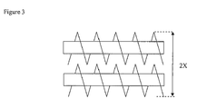
Figure 3 shows in schematic form a top view of a section of twin-screws of a twin screw extruder. In this case the width is 2*X.
Claims (7)
- An extruder comprising:(i) two or more barrel sections arranged sequentially from:(a) an upstream feed barrel section to which polymer feedstock to be extruded is fed, the upstream feed barrel section containing one or more screws each having a diameter of X; to(b) a downstream barrel section from which melted polymer is passed to a die and extruded; and(ii) one or more feed ports for feeding polymer feedstock to be extruded into the extruder at its upstream end,characterised in that the total length of the one or more feed ports through which polymer feedstock is introduced is greater than 2*X.
- An extruder according to claim 1 which comprises three of more barrel sections.
- An extruder according to claim 1 or claim 2 which has a single feed port which has a length greater than 2*X.
- An extruder according to any one of the preceding claims in which the total length of the one or more feed ports through which polymer is introduced is greater than 2.5*X.
- An extruder according to any one of the preceding claims in which the diameter of the screw or screws in the feed port barrel section is 200 mm or greater.
- A process for extrusion of polymer comprising feeding a polymer feedstock to the feed port of an extruder as described in any one of claims 1 to 5.
- A process according to claim 6 wherein the polymer feedstock is in the form of a powder having a flowability ratio of less than 6.
Priority Applications (10)
| Application Number | Priority Date | Filing Date | Title |
|---|---|---|---|
| EP08103227A EP2113364A1 (en) | 2008-03-31 | 2008-03-31 | Apparatus and process |
| EP09728883.1A EP2259909B1 (en) | 2008-03-31 | 2009-03-18 | Extruder and process for extruding a polymer |
| CN2009801125410A CN101983121A (en) | 2008-03-31 | 2009-03-18 | Extruder and process for extruding a polymer |
| BRPI0910432-1A BRPI0910432B1 (en) | 2008-03-31 | 2009-03-18 | POLYMER EXTRUSION PROCESS |
| JP2011502328A JP5363558B2 (en) | 2008-03-31 | 2009-03-18 | Extruder and method for extruding polymer |
| US12/736,147 US8865041B2 (en) | 2008-03-31 | 2009-03-18 | Extruder and process for extruding a polymer |
| SG2013020631A SG188924A1 (en) | 2008-03-31 | 2009-03-18 | Extruder and process for extruding a polymer |
| PCT/EP2009/053204 WO2009121721A1 (en) | 2008-03-31 | 2009-03-18 | Extruder and process for extruding a polymer |
| RU2010144311/05A RU2496642C2 (en) | 2008-03-31 | 2009-03-18 | Extruder and method of polymer extrusion |
| US14/487,823 US20150017274A1 (en) | 2008-03-31 | 2014-09-16 | Extruder and process for extruding a polymer |
Applications Claiming Priority (1)
| Application Number | Priority Date | Filing Date | Title |
|---|---|---|---|
| EP08103227A EP2113364A1 (en) | 2008-03-31 | 2008-03-31 | Apparatus and process |
Publications (1)
| Publication Number | Publication Date |
|---|---|
| EP2113364A1 true EP2113364A1 (en) | 2009-11-04 |
Family
ID=39691041
Family Applications (2)
| Application Number | Title | Priority Date | Filing Date |
|---|---|---|---|
| EP08103227A Withdrawn EP2113364A1 (en) | 2008-03-31 | 2008-03-31 | Apparatus and process |
| EP09728883.1A Active EP2259909B1 (en) | 2008-03-31 | 2009-03-18 | Extruder and process for extruding a polymer |
Family Applications After (1)
| Application Number | Title | Priority Date | Filing Date |
|---|---|---|---|
| EP09728883.1A Active EP2259909B1 (en) | 2008-03-31 | 2009-03-18 | Extruder and process for extruding a polymer |
Country Status (8)
| Country | Link |
|---|---|
| US (2) | US8865041B2 (en) |
| EP (2) | EP2113364A1 (en) |
| JP (1) | JP5363558B2 (en) |
| CN (1) | CN101983121A (en) |
| BR (1) | BRPI0910432B1 (en) |
| RU (1) | RU2496642C2 (en) |
| SG (1) | SG188924A1 (en) |
| WO (1) | WO2009121721A1 (en) |
Families Citing this family (3)
| Publication number | Priority date | Publication date | Assignee | Title |
|---|---|---|---|---|
| GB201620525D0 (en) | 2016-12-02 | 2017-01-18 | Ineos Europe Ag | Process |
| CN108407255B (en) * | 2018-04-12 | 2024-03-01 | 国材(苏州)新材料科技有限公司 | Feeding regulator of screw extruder |
| CN109230467A (en) * | 2018-09-29 | 2019-01-18 | 安徽科茂能源科技有限公司 | A kind of piston type charger |
Citations (5)
| Publication number | Priority date | Publication date | Assignee | Title |
|---|---|---|---|---|
| WO1996032242A1 (en) * | 1995-04-11 | 1996-10-17 | Helmut Bacher | Device for preparing thermoplastic material |
| US5594074A (en) * | 1995-02-21 | 1997-01-14 | Shell Oil Company | Process for improving processability of ultra low melt viscosity polymer |
| JP2000284545A (en) * | 1999-03-22 | 2000-10-13 | Xerox Corp | Production of carrier |
| US20020192891A1 (en) * | 2001-03-14 | 2002-12-19 | Sumitomo Chemical Company, Limited | Manufacturing method of film-like materials of resin and film-like materials of resin |
| JP2006199913A (en) * | 2004-12-24 | 2006-08-03 | Fuji Photo Film Co Ltd | Cellulose acylate film and its production method |
Family Cites Families (17)
| Publication number | Priority date | Publication date | Assignee | Title |
|---|---|---|---|---|
| US3082816A (en) * | 1955-05-18 | 1963-03-26 | Welding Engineers | Process for treating material |
| DE2842162A1 (en) | 1978-09-28 | 1980-04-17 | Anton Kolb Maschinenbau | Thermoplastics scrap recovery plant - having material macerated by counter-rotating profiled rollers and passing to consolidating screw and final extruders |
| DE3430254A1 (en) * | 1984-08-17 | 1986-02-27 | Hoechst Ag, 6230 Frankfurt | SNAIL EXTRUDERS |
| US5169582A (en) * | 1985-05-08 | 1992-12-08 | Ems-Inventa Ag | Method and apparatus for the production of thermoplastic caprolactam containing molding compositions |
| DE4114541C2 (en) * | 1990-12-14 | 1994-05-26 | Berstorff Gmbh Masch Hermann | Degassing extruder |
| JPH0729295B2 (en) * | 1992-03-17 | 1995-04-05 | 森山 正夫 | Four-screw extruder |
| FI101950B (en) * | 1996-12-12 | 1998-09-30 | Uponor Innovation Ab | Method and apparatus for recovering recyclable plastic material i and plastic product made with a press device |
| US5824709A (en) * | 1994-11-16 | 1998-10-20 | Suka; Motoshi | Method for recycling waste plastic material containing styrene polymer |
| US6562192B1 (en) * | 1998-10-02 | 2003-05-13 | Kimberly-Clark Worldwide, Inc. | Absorbent articles with absorbent free-flowing particles and methods for producing the same |
| US6328919B1 (en) * | 1999-02-16 | 2001-12-11 | The Dow Chemical Company | Method for extruding polycarbonate of low bulk density |
| TWI296635B (en) * | 2000-09-08 | 2008-05-11 | Asahi Kasei Chemicals Corp | |
| RU2304511C2 (en) * | 2001-12-19 | 2007-08-20 | Пирелли Пнеуматичи С.П.А. | Method and device for continuous producing of elastomeric composition |
| DE10233214B4 (en) | 2002-07-22 | 2005-01-27 | 3+Extruder Gmbh | Extruder for continuous processing and / or processing of flowable materials |
| US20040204551A1 (en) * | 2003-03-04 | 2004-10-14 | L&L Products, Inc. | Epoxy/elastomer adduct, method of forming same and materials and articles formed therewith |
| AT413511B (en) * | 2003-06-05 | 2006-03-15 | Bacher Helmut | DEVICE FOR PREPARING PLASTIC MATERIAL FOR RECYCLING PURPOSES |
| JP4001596B2 (en) | 2004-10-05 | 2007-10-31 | 株式会社日本製鋼所 | Cylinder hopper |
| BRPI0708829A2 (en) * | 2006-03-24 | 2012-03-13 | Century-Board Usa, Llc | methods of forming composite polymeric material in an extruder |
-
2008
- 2008-03-31 EP EP08103227A patent/EP2113364A1/en not_active Withdrawn
-
2009
- 2009-03-18 CN CN2009801125410A patent/CN101983121A/en active Pending
- 2009-03-18 JP JP2011502328A patent/JP5363558B2/en active Active
- 2009-03-18 BR BRPI0910432-1A patent/BRPI0910432B1/en active IP Right Grant
- 2009-03-18 EP EP09728883.1A patent/EP2259909B1/en active Active
- 2009-03-18 RU RU2010144311/05A patent/RU2496642C2/en active
- 2009-03-18 US US12/736,147 patent/US8865041B2/en active Active
- 2009-03-18 WO PCT/EP2009/053204 patent/WO2009121721A1/en active Application Filing
- 2009-03-18 SG SG2013020631A patent/SG188924A1/en unknown
-
2014
- 2014-09-16 US US14/487,823 patent/US20150017274A1/en not_active Abandoned
Patent Citations (7)
| Publication number | Priority date | Publication date | Assignee | Title |
|---|---|---|---|---|
| US5594074A (en) * | 1995-02-21 | 1997-01-14 | Shell Oil Company | Process for improving processability of ultra low melt viscosity polymer |
| WO1996032242A1 (en) * | 1995-04-11 | 1996-10-17 | Helmut Bacher | Device for preparing thermoplastic material |
| US5988865A (en) * | 1995-04-11 | 1999-11-23 | Bacher; Helmut | Device for preparing thermoplastic material |
| JP2000284545A (en) * | 1999-03-22 | 2000-10-13 | Xerox Corp | Production of carrier |
| US6355194B1 (en) * | 1999-03-22 | 2002-03-12 | Xerox Corporation | Carrier pelletizing processes |
| US20020192891A1 (en) * | 2001-03-14 | 2002-12-19 | Sumitomo Chemical Company, Limited | Manufacturing method of film-like materials of resin and film-like materials of resin |
| JP2006199913A (en) * | 2004-12-24 | 2006-08-03 | Fuji Photo Film Co Ltd | Cellulose acylate film and its production method |
Non-Patent Citations (2)
| Title |
|---|
| DATABASE WPI Week 199647, Derwent World Patents Index; AN 1996-476933 * |
| DATABASE WPI Week 200109, Derwent World Patents Index; AN 2001-074566 * |
Also Published As
| Publication number | Publication date |
|---|---|
| EP2259909A1 (en) | 2010-12-15 |
| SG188924A1 (en) | 2013-04-30 |
| RU2010144311A (en) | 2012-05-10 |
| CN101983121A (en) | 2011-03-02 |
| WO2009121721A1 (en) | 2009-10-08 |
| BRPI0910432B1 (en) | 2019-07-02 |
| JP2011516302A (en) | 2011-05-26 |
| US20110001261A1 (en) | 2011-01-06 |
| RU2496642C2 (en) | 2013-10-27 |
| US20150017274A1 (en) | 2015-01-15 |
| EP2259909B1 (en) | 2019-01-16 |
| US8865041B2 (en) | 2014-10-21 |
| JP5363558B2 (en) | 2013-12-11 |
| BRPI0910432A2 (en) | 2015-09-29 |
Similar Documents
| Publication | Publication Date | Title |
|---|---|---|
| JP4768018B2 (en) | Reverse rotation twin screw extruder | |
| EP1252999B1 (en) | Kneading apparatus for kneading rubber-based composition using the same | |
| EP1600276B1 (en) | Use of a counter-rotating twin screw extruder for compounding multimodal polymer compositions | |
| EP2168743B2 (en) | Melting kneading devolatilizing extruder | |
| EP3311982B1 (en) | Heat-shrinkable tube and method for producing same | |
| US20050140048A1 (en) | Method of injection molding or extruding a polymer composition using a low compression screw | |
| US20170120499A1 (en) | Extrusion process for polyethylene polymers | |
| JP5137613B2 (en) | Kneading disc segment and twin screw extruder | |
| CN102205620A (en) | Differential-speed conical twin-screw extruder | |
| EP2113364A1 (en) | Apparatus and process | |
| JP5536705B2 (en) | Method for producing glass fiber reinforced thermoplastic resin composition pellets | |
| WO2012165469A1 (en) | Material kneading device and material kneading method | |
| AU740820B2 (en) | Plasticizing screw | |
| CN101920551B (en) | Bolt special for internally and externally shielded cable material | |
| JP5410696B2 (en) | Extruder screw and method for producing polymethylpentene film | |
| TWI496675B (en) | Glass fiber reinforced thermoplastic synthetic resin composites for the production of compressed products | |
| US20050127559A1 (en) | Homogenizing multimodal polymer | |
| JPH0459220A (en) | High speed extrusion method for thermoplastic resin | |
| Alavi et al. | Twin-screw extruder and effective parameters on the HDPE extrusion process | |
| JP4707377B2 (en) | Molding method for thermoplastic resin film | |
| Wiedmann et al. | Twin-screw extruders in ceramic extrusion | |
| JPH0138658B2 (en) | ||
| CN202062621U (en) | Differential three-conical-screw rod extruder with screw rods arranged in horizontal line | |
| JP2006240240A (en) | Screw type kneading extruder |
Legal Events
| Date | Code | Title | Description |
|---|---|---|---|
| PUAI | Public reference made under article 153(3) epc to a published international application that has entered the european phase |
Free format text: ORIGINAL CODE: 0009012 |
|
| AK | Designated contracting states |
Kind code of ref document: A1 Designated state(s): AT BE BG CH CY CZ DE DK EE ES FI FR GB GR HR HU IE IS IT LI LT LU LV MC MT NL NO PL PT RO SE SI SK TR |
|
| AX | Request for extension of the european patent |
Extension state: AL BA MK RS |
|
| AKX | Designation fees paid | ||
| REG | Reference to a national code |
Ref country code: DE Ref legal event code: 8566 |
|
| STAA | Information on the status of an ep patent application or granted ep patent |
Free format text: STATUS: THE APPLICATION IS DEEMED TO BE WITHDRAWN |
|
| 18D | Application deemed to be withdrawn |
Effective date: 20100505 |