EP2113328B1 - Handseilsäge - Google Patents
Handseilsäge Download PDFInfo
- Publication number
- EP2113328B1 EP2113328B1 EP08020292A EP08020292A EP2113328B1 EP 2113328 B1 EP2113328 B1 EP 2113328B1 EP 08020292 A EP08020292 A EP 08020292A EP 08020292 A EP08020292 A EP 08020292A EP 2113328 B1 EP2113328 B1 EP 2113328B1
- Authority
- EP
- European Patent Office
- Prior art keywords
- blade body
- swivel blade
- carriage
- saw
- cable
- Prior art date
- Legal status (The legal status is an assumption and is not a legal conclusion. Google has not performed a legal analysis and makes no representation as to the accuracy of the status listed.)
- Not-in-force
Links
- 238000005096 rolling process Methods 0.000 claims abstract description 6
- 230000007704 transition Effects 0.000 claims abstract description 3
- 238000005520 cutting process Methods 0.000 claims description 37
- 239000004567 concrete Substances 0.000 claims description 4
- 230000004224 protection Effects 0.000 claims description 3
- 239000004566 building material Substances 0.000 claims description 2
- 239000011150 reinforced concrete Substances 0.000 claims description 2
- 239000004575 stone Substances 0.000 claims description 2
- 239000000463 material Substances 0.000 description 7
- 230000009191 jumping Effects 0.000 description 3
- 238000012423 maintenance Methods 0.000 description 2
- 241000209035 Ilex Species 0.000 description 1
- 229910000831 Steel Inorganic materials 0.000 description 1
- 230000000712 assembly Effects 0.000 description 1
- 238000000429 assembly Methods 0.000 description 1
- 230000006835 compression Effects 0.000 description 1
- 238000007906 compression Methods 0.000 description 1
- 238000010276 construction Methods 0.000 description 1
- 239000004035 construction material Substances 0.000 description 1
- 239000000498 cooling water Substances 0.000 description 1
- 230000003247 decreasing effect Effects 0.000 description 1
- 230000000694 effects Effects 0.000 description 1
- 210000003746 feather Anatomy 0.000 description 1
- 230000036541 health Effects 0.000 description 1
- 238000004519 manufacturing process Methods 0.000 description 1
- 238000005457 optimization Methods 0.000 description 1
- 230000002093 peripheral effect Effects 0.000 description 1
- 230000009979 protective mechanism Effects 0.000 description 1
- 230000009467 reduction Effects 0.000 description 1
- 239000010959 steel Substances 0.000 description 1
- 238000003860 storage Methods 0.000 description 1
- 239000000126 substance Substances 0.000 description 1
Images


Classifications
-
- B—PERFORMING OPERATIONS; TRANSPORTING
- B23—MACHINE TOOLS; METAL-WORKING NOT OTHERWISE PROVIDED FOR
- B23D—PLANING; SLOTTING; SHEARING; BROACHING; SAWING; FILING; SCRAPING; LIKE OPERATIONS FOR WORKING METAL BY REMOVING MATERIAL, NOT OTHERWISE PROVIDED FOR
- B23D57/00—Sawing machines or sawing devices not covered by one of the preceding groups B23D45/00 - B23D55/00
- B23D57/0007—Sawing machines or sawing devices not covered by one of the preceding groups B23D45/00 - B23D55/00 using saw wires
- B23D57/0015—Sawing machines or sawing devices not covered by one of the preceding groups B23D45/00 - B23D55/00 using saw wires hand-held or hand-operated
-
- B—PERFORMING OPERATIONS; TRANSPORTING
- B23—MACHINE TOOLS; METAL-WORKING NOT OTHERWISE PROVIDED FOR
- B23D—PLANING; SLOTTING; SHEARING; BROACHING; SAWING; FILING; SCRAPING; LIKE OPERATIONS FOR WORKING METAL BY REMOVING MATERIAL, NOT OTHERWISE PROVIDED FOR
- B23D57/00—Sawing machines or sawing devices not covered by one of the preceding groups B23D45/00 - B23D55/00
- B23D57/003—Sawing machines or sawing devices working with saw wires, characterised only by constructional features of particular parts
- B23D57/0053—Sawing machines or sawing devices working with saw wires, characterised only by constructional features of particular parts of drives for saw wires; of wheel mountings; of wheels
-
- B—PERFORMING OPERATIONS; TRANSPORTING
- B23—MACHINE TOOLS; METAL-WORKING NOT OTHERWISE PROVIDED FOR
- B23D—PLANING; SLOTTING; SHEARING; BROACHING; SAWING; FILING; SCRAPING; LIKE OPERATIONS FOR WORKING METAL BY REMOVING MATERIAL, NOT OTHERWISE PROVIDED FOR
- B23D57/00—Sawing machines or sawing devices not covered by one of the preceding groups B23D45/00 - B23D55/00
- B23D57/003—Sawing machines or sawing devices working with saw wires, characterised only by constructional features of particular parts
- B23D57/0069—Sawing machines or sawing devices working with saw wires, characterised only by constructional features of particular parts of devices for tensioning saw wires
-
- B—PERFORMING OPERATIONS; TRANSPORTING
- B28—WORKING CEMENT, CLAY, OR STONE
- B28D—WORKING STONE OR STONE-LIKE MATERIALS
- B28D1/00—Working stone or stone-like materials, e.g. brick, concrete or glass, not provided for elsewhere; Machines, devices, tools therefor
- B28D1/02—Working stone or stone-like materials, e.g. brick, concrete or glass, not provided for elsewhere; Machines, devices, tools therefor by sawing
- B28D1/08—Working stone or stone-like materials, e.g. brick, concrete or glass, not provided for elsewhere; Machines, devices, tools therefor by sawing with saw-blades of endless cutter-type, e.g. chain saws, i.e. saw chains, strap saws
Definitions
- the invention relates to a hand wire saw for cutting natural stone, concrete, reinforced concrete and similar building materials.
- a hand wire saw according to the preamble of claim 1 is known from WO 2005/070598 and the DE 102005021284 known.
- the DE 100 50 732 provides a chain saw for cutting concrete in which a drive head drives a sprocket, a sprocket aligned with the sprocket is attached to the drive head and a rotating saw chain is pulled around the sprocket and sprocket to be rapidly driven by the sprocket in a circulating path , Teeth protruding from the saw chain will eat into the material to be cut, removing and shredding material from the kerf and cutting the teeth into a slot in the material.
- the US 6,178,960 B1 discloses a hand wire saw, comprising a drive wheel with a guide groove for the sawing wire, a guide blade, at its tip a receptacle for a Seilbowungszahnrad with gaps and transport surfaces, which are integrally formed on the outer circumference of the cable guide gear.
- the Seilzhouangszahnrad is rotatably mounted on the guide blade by means of a rotatable shaft, brackets and rings.
- the saw rope endlessly revolves around the drive wheel, the guide bar and the cable feed gear.
- a second variant of the hand wire saw provides a shortened guide blade with a cable guide gear, which has a large diameter, so receives the size of a saw blade and should be usable as a circular saw.
- the basic construction of the hand wire saw does not protect the saw rope from jumping out of the cable gear.
- pressure is applied to the sawing wire gives way to the sword, whereby the cutting elements of the sawing cable can also store on the guide surfaces of the cable guide gear and the sawing cable can jump out of the cable guide gear, because the wire saw provides no rope tension.
- the object is achieved by the features of claim 1, by the hand wire saw on a support member a base body and a carriage, two, arranged below the drive pulleys, pulleys, a sword body with two outer layers and a concave contour and two forked ends and a middle With a round opening, a cut roller and a spring between the carriage and the sword body.
- the pulleys and the carriage are arranged on the main body of the support member, arranged on the carriage of the electric motor and the drive wheel and movably guided on the base body and the carriage biased by the spring between the carriage and the sword body against the pulleys is, during the cutting process, when pressure on the sawing cable, the cutting roller and the sword body, with the help of the pulleys and the prestressed carriage to continuously tension the sawing wire and is rotatable about its axis.
- the cutting role which is rotatably mounted in the round breakthrough of the central position of the sword body with rolling elements, wherein the sawing wire is to be fixed and held continuously by the forked ends at the transition points between sword body and cutting role on the circumference of the cutting role.
- the sawing wire and the sword body the sawing wire is continuously tensioned by means of the two movable deflection rollers, the spring-biased drive roller and the sword body and rotated about its axis to ensure even wear to ensure the cutting elements on the sawing wire and to avoid the jumping off of the sawing cable from the cutting role, which in particular work interruptions with serious health consequences for the user and the resulting consequential costs are avoidable.
- the carrier part according to the invention is also advantageous.
- the carrier part, with a base body, molded recesses and handle elements, two frontally open channels and a carriage is equipped with a recording of all, for the Function essential, support assemblies as well as a compact and lightweight design of the hand cord saw allows.
- this does not exclude a housing cover when needed.
- the pulleys are roller-mounted and arranged below the drive wheel on the main body of the support member, wherein the, arranged between the carriage and the sword body spring generates a bias between the drive wheel and the pulleys and the sword body and wherein in the operating state of the hand wire saw at any pressure direction on the sawing cable, the cutting role and the sword body, the tension of the sawing wire is to be maintained continuously.
- This design feature the pulleys are used as rope tension. The saw wire remains under tension during the entire cutting process and can not jump off the cutting roll.
- the inventive design of the sword body which has two outer layers, each having a concave contour with two molded fork-shaped ends and a middle layer with a molded round opening at its top, the three layers of the sword body are positively connected to each other and have breakthroughs in their surface.
- the design of the sword body is used for safe guidance and fixation of the sawing cable and for storage of the cutting roller on the sword body.
- the breakthroughs in the surface of the sword body also help to optimize the weight of the hand wire saw.
- the cutting role according to the invention is formed in a particularly advantageous manner from two annular discs, each having a rounded bevel on its outer periphery and are releasably connected to each other via the opening in the middle position of the sword body, with its outer Ring surface protrude into the concave contour of the outer layers, with these form a plane and together have a thickness that is smaller than the diameter of the sawing cable.
- the cutting roller according to the invention no axle bearing on the sword body is required and the weight of the hand wire saw is further reduced.
- the cutting role can be easily replaced by its two-part design and spares the sword body. Due to the minimal thickness of the cut roller, a continuous rotation of the cut elements on the sawing wire around its own axis and thus its uniform wear is also ensured.
- the use of sawing cables has a further, in particular cost-effective effect.
- the opposite of an electric drive arranged in the edge region of the support member gas pressure springs, together with two sleeves for protection against the sawing wire depending on the direction of pressure on the cutting role against the cutting direction individually or extendable together from the support member and retractable at declining pressure and which serve together with the sleeves as a protective mechanism for the user of the hand wire saw.
- the guidance of the sawing cable ensured by the, connected to the electric drive, to the first, below the drive wheel, arranged pulley, in the first sleeve along the first edge of the sword body on the cut roller in the second sleeve along the opposite second edge of the sword body on the second, arranged below the drive pulleys pulleys back to the drive endless guidance of the sawing cable and its continuous tension and avoids the jumping off of the sawing cable from the cutting roller.
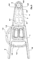
- FIG. 1 shows the side view of a basic representation of the hand wire saw according to the invention.
- a carrier part 1 with a basic body 1.1, molded recesses 1.2, handle elements 1.3, two frontally open channels 1.4 and a carriage 1.5 serves to accommodate all components of the hand wire saw according to the invention.
- On the base 1.1 of the carriage 1.5 is movably mounted and arranged thereon an electric drive 7 with a drive wheel 2. Below the drive wheel 2 are two, not shown.
- Deflection rollers 3 arranged on the base body 1.1.
- the spring 6 is preferably a compression spring, and is, not shown in the drawing, arranged between the carriage 1.5 and the sword body 4, whereby the heavy body 4 with the cutting roller 5 and the Drive wheel 2 are biased against the pulleys 3.
- the spring 6 ensures in this way a continuous tension of the sawing cable 7.
- a gas spring 9 and a sleeve 10 for protection against the sawing wire 7, which are guided in the channels 1.4 of the body 1.1, wherein the sleeves run to the end of the sword body 4. Above the main body 1.1 of the sword body 4 is attached.
- the sword body 4 is preferably made of sheet steel and consists, as in Fig.2 and Fig.3 shown in more detail, from a first outer layer 4.1 and a second outer layer 4.3, each having at one end a concave contour 4.4 with two forked ends 4.5 and a middle layer 4.2, which is enclosed by the two outer layers 4.1 and 4.3 and protrudes between the outer layers 4.1 and 4.3.
- the outstanding between the two layers 4.1 and 4.3 part of the middle layer 4.2 of the sword body 4 is provided at its tip with a molded-through breakthrough 4.6.
- the layers 4.1 to 4.3 are non-positively connected to each other and equipped, for further weight optimization, in the surfaces with through holes 4.7.
- a cut roller 5 with rolling elements 11 is rotatably mounted in the opening 4.6 of the middle layer 4.2.
- the cutting roller 5 consists of two annular discs 5.1 and 5.2, which are provided at its outer periphery with a rounded bevel 5.3 and are detachably connected to each other via the opening 4.6 of the heavy body 4.
- the annular discs 5.1 and 5.2 are connected to each other so that their rounded slopes 5.3 of the cutting roller 5 form a concave peripheral surface.
- the annular discs 5.1 and 5.2 respectively project into the concave contour 4.4 of the outer layers 4.1 and 4.3 of the sword body 4, whereby the outer annular surfaces 5.1 and 5.2 form a plane with the surfaces of the outer layers 4.1 and 4.3 of the sword body 4.
- the cutting roller 5 is executed in the assembled state in a thickness which is thinner than the largest diameter of the sawing cable 7.
- the sawing cable 7 preferably has a diameter of 6 mm.
- the cut roller 5 is not stronger than 4mm for this reason.
- the sawing wire 7 is guided endlessly from the drive wheel 2 via the first deflection roller 3 along the first edge of the sword body 4 via the cutting roller 5 along the opposite second edge of the sword body 4 via the second deflection rollers 3.
- Figure 5 shows how the cutting process pressure on the sawing cable 7, the cutting roller 5 and the sword body 4 is exercised and depending on the printing direction of the Gas springs 9 are inserted with the sleeves 10 in the frontally open channels 1.4 of the support member 1 individually or together and moved out the end of the respective channel 1.4. With decreasing pressure, the sleeves 10 are retracted with the gas springs 9 and returned to their old position.
Landscapes
- Engineering & Computer Science (AREA)
- Mechanical Engineering (AREA)
- Mining & Mineral Resources (AREA)
- Processing Of Stones Or Stones Resemblance Materials (AREA)
- Finish Polishing, Edge Sharpening, And Grinding By Specific Grinding Devices (AREA)
- Polishing Bodies And Polishing Tools (AREA)
- Non-Silver Salt Photosensitive Materials And Non-Silver Salt Photography (AREA)
- Paper (AREA)
Description
- Die Erfindung betrifft eine Handseilsäge zum zerschneiden von Naturstein, Beton, Stahlbeton und ähnlichen Baustoffen. Eine Handseilsäge gemäß dem Oberbegriff von Anspruch 1 ist aus der
WO 2005/070598 und derDE 102005021284 bekannt. - Es sind Handsägen bekannt, die mit einem Sägeblatt arbeiten. Das Problem der Nutzung von Sägeblättern besteht darin, daß die erreichbare Schnittiefe vom Radius des Sägeblattes abhängig ist. Bei erforderlichen großen Schnittiefen, benötigt man Sägeblätter mit großem Durchmesser. Das macht die Säge nicht nur schwer und unhandlich. Mit Sägeblättern können außerdem keine rechten Winkel gesägt werden, was zu zeitaufwendigen Nacharbeiten und zu erheblichem Materialverlust führt. Gleiches trifft auch bei sogenannten Ringsägen zu.
- Es sind auch Handsägen bekannt, die mit einer Kette arbeiten. Die
DE 100 50 732 sieht eine Kettensäge zum schneiden von Beton vor, bei der ein Antriebskopf ein Kettenrad antreibt, ein mit dem Kettenrad ausgerichtetes Schwert am Antriebskopf befestigt ist und eine umlaufende Sägekette um das Schwert und das Kettenrad gezogen wird, um vom Kettenrad schnell auf einem Umlaufweg angetrieben zu werden. Von der Sägekette vorstehende Zähne fressen sich in das zu schneidende Material ein, wobei das im Sägeschlitz anfallende Material abgetragen und zerkleinert wird und die Zähne einen Schlitz in das Material schneiden. Beim Schnitt von Baumaterialien wie beispielsweise Beton entsteht durch das zerkleinerte Material in Verbindung mit dem Kühlwasser der Kettensäge eine schlammige Substanz, die sich in den Kettengliedern festsetzt, frißt und die Kette sehr schnell verschleißen läßt. Die Folge ist ein häufiges Auswechseln der Kette, die nicht nur teuer ist, sondern auch zu häufiger Wartung und zum Ausfall der Handsägen führt. - Die
US 6,178,960 B1 offenbart eine Handseilsäge, aufweisend ein Antriebsrad mit einer Führungsnut für das Sägeseil, ein Führungsschwert, an dessen Spitze eine Aufnahme für ein Seilfuhrungszahnrad mit Zwischenräumen und Transportflächen, die am äußeren Umfang des Seilführungszahnrads angeformt sind. Dabei ist das Seilführangszahnrad an dem Führungsschwert mit Hilfe einer drehbaren Welle, Halterungen und Ringen drehbar gelagert. Das Sägeseil umläuft endlos das Antriebsrad, das Führungsschwert und das Seilfubrungszahnrad. Beim Umlaufen des Sägeseils über das Seilfuhrungszahnrad sollen die Schnittelemente des Sägeseils in die Zwischenräume des Seilführungszahnrads einrasten und die Zwischenräume des Sägeseils zwischen den Schnittelementen sollen sich um die Transportflächen des Seifühmngszahnrads legen, wobei die Schnittelemente des Sägeseils die Zwischenräume überragen und das zu schneidende Material abtragen sollen. Eine zweite Variante der Handseilsäge sieht ein verkürztes Führungsschwert mit einem Seilsführungszahnrad vor, das einen großen Durchmesser aufweise, so die Größe eines Sägeblatts erhält und als Kreissäge verwendbar sein soll. - Die Grundkonstruktion der Handseilsäge bewahrt das Sägeseil nicht vor dem Herausspringen aus dem Seilfühnmgszahnrad. Bei Druckausübung auf das Sägeseil gibt das Schwert nach, wodurch die Schnittelemente des Sägeseils auch auf den Führungsflächen des Seilführungszahnrads lagern können und das Sägeseil von dem Seilführungszahnrad herausspringen kann, weil die Seilsäge keine Seilspannung vorsieht.
- Es war deshalb Aufgabe der Erfindung eine Handseilsäge zu schaffen, die eine kompakte Bauform und ein, gegenüber dem Stand der Technik, optimiertes Gewicht aufweist, die eine hohe Lebensdauer des Sägeseils, eine optimale Wartungsquote und eine kostengünstige Herstellung sowie eine erhebliche Reduzierung von Arbeitsunfällen gewährleistet.
- Die Aufgabe wird mit den Merkmalen des Anspruchs 1 gelöst, indem die Handseilsäge an einem Trägerteil einen Grundkörper und einem Schlitten, zwei, unterhalb des Antriebsrads angeordnete, Umlenkrollen, einen Schwertkörper mit zwei äußeren Lagen und jeweils einer konkaven Kontur sowie zwei gabelförmigen Enden und einer mittleren Lage mit einem runden Durchbruch, eine Schnittrolle und eine Feder zwischen dem Schlitten und dem Schwertkörper aufweist.
- Von besonderem Vorteil ist es, daß an dem Grundkörper des Trägerteils die Umlenkrollen und der Schlitten angeordnet sind, am Schlitten der Elektromotor und das Antriebsrad angeordnet und am Grundkörper beweglich geführt ist und der Schlitten durch die Feder zwischen dem Schlitten und dem Schwertkörper entgegen der Umlenkrollen vorgespannt ist, wobei während des Schneidvorgangs, bei Druck auf das Sägeseil, die Schnittrolle und den Schwertkörper, mit Hilfe der Umlenkrollen und des vorgespannten Schlittens das Sägeseil kontinuierlich zu spannen und um seine Achse drehbar ist.
- Hervorzuheben ist die Schnittrolle, die in dem runden Durchbruch der mittleren Lage des Schwertkörpers mit Wälzkörpern drehbar gelagert ist, wobei das Sägeseil durch die gabelförmigen Enden an den Übergangsstellen zwischen Schwertkörper und Schnittrolle am Umfang der Schnittrolle kontinuierlich zu fixieren und zu halten ist.
- Während des Schneidvorgangs wird außerdem, durch Druck auf das Sägeseil, die Schnittrolle und den Schwertkörper, das Sägeseil mit Hilfe der beiden beweglichen Umlenkrollen, der, durch die Feder vorgespannten, Antriebsrolle und des Schwertkörpers kontinuierlich gespannt und um seine Achse gedreht, um einen gleichmäßigen Verschleiß der Schnittelemente am Sägeseil zu gewährleisten und das Herunterspringen des Sägeseils von der Schnittrolle zu vermeiden, wodurch insbesondere Arbeitsausfälle mit schwerwiegenden gesundheitlichen Folgen für die Benutzer und die daraus entstehenden Folgekosten vermeidbar sind.
- Vorteilhaft ist des weiteren die material- und gewichtsreduzierende konstruktive Ausgestaltung des erfindungsgemäßen Trägerteils, nach Anspruch 2, nach der das Trägerteil, mit einem Grundkörper, eingeformten Ausnehmungen und Griffelementen, zwei stirnseitig offenen Kanälen und einem Schlitten ausgestattet ist, die eine Aufnahme aller, für die Funktion wesentlichen, Baugruppen unterstützen sowie eine kompakte und leichtgewichtige Bauform der Handseilsäge ermöglicht. Das schließt selbstverständlich eine Gehäuseabdeckung bei Bedarf nicht aus.
- Von funktionswesentlicher Bedeutung sind die Umlenkrollen, gemäß Anspruch 3, die wälzgelagert und unterhalb des Antriebsrads an dem Grundkörper des Trägerteils angeordnet sind, wobei die, zwischen dem Schlitten und dem Schwertkörper angeordnete, Feder eine Vorspannung zwischen dem Antriebsrad und den Umlenkrollen sowie dem Schwertkörper erzeugt und wobei im Betriebszustand der Handseilsäge bei beliebiger Druckrichtung auf das Sägeseil, die Schnittrolle und den Schwertkörper, die Spannung des Sägeseils kontinuierlich aufrecht zu erhalten ist. Durch dieses konstruktive Merkmal werden die Umlenkrollen als Seilspannung genutzt. Das Sägeseil bleibt während des gesamten Schneidvorgangs unter Spannung und kann auch nicht von der Schnittrolle springen.
- Besonders vorteilhaft ist die erfindungsgemäße Gestaltung des Schwertkörpers, nach Anspruch 4, der zwei äußere Lagen mit jeweils einer konkaven Kontur mit zwei angeformten gabelförmigen Enden und eine mittlere Lage mit einem eingeformten runden Durchbruch an ihrer Spitze aufweist, die drei Lagen des Schwertkörpers kraftschlüssig miteinander verbunden sind und in ihrer Fläche Durchbrüche aufweisen. Die Ausführung des Schwertkörpers dient zur sicheren Führung und Fixierung des Sägeseils und zur Lagerung der Schnittrolle am Schwertkörper. Die Durchbrüche in der Fläche des Schwertkörpers unterstützen darüber hinaus die Optimierung des Gewichts der Handseilsäge.
- Hervorzuheben ist auch die erfindungsgemäße Schnittrolle, nach Anspruch 5, Sie ist in besonders vorteilhafter Weise aus zwei Ringscheiben gebildet, die an ihrem äußeren Umfang jeweils eine abgerundete Schräge aufweisen und über den Durchbruch in der mittleren Lage des Schwertkörpers lösbar miteinander verbunden sind, mit ihrer äußeren Ringfläche in die konkave Kontur der äußeren Lagen hineinragen, mit diesen eine Ebene bilden und die gemeinsam eine Stärke aufweisen, die kleiner als der Durchmesser des Sägeseils ist. Mit der erfindungsgemäßen Schnittrolle ist keine Achslagerung am Schwertkörper erforderlich und das Gewicht der Handseilsäge wird weiter reduziert. Außerdem kann die Schnittrolle durch ihre zweiteilige Ausführung leicht ausgewechselt werden und schont den Schwertkörper. Durch die minimale Stärke der Schnittrolle wird außerdem eine kontinuierliche Drehung der Schnittelemente am Sägeseil um deren eigene Achse und damit deren gleichmäßiger Verschleiß gewährleistet. Die Nutzung von Sägeseilen hat eine weitere, insbesondere kostengünstige Wirkung.
- Vorteilhaft für die Handhabung und zur Gewährleistung einer kompakten Bauweise sind, nach Anspruch 6, die, gegenüberliegend von einem Elektroantrieb, im Randbereich des Trägerteils angeordneten Gasdruckfedern, die zusammen mit zwei Hülsen zum Schutz vor dem Sägeseil je nach Druckrichtung auf die Schnittrolle entgegen der Schnittrichtung einzeln oder zusammen aus dem Trägerteil ausfahrbar und bei nachlassendem Druck wieder einfahrbar sind und die zusammen mit den Hülsen als Schutzmechanismus für den Benutzer der Handseilsäge dienen.
- Schließlich gewährleistet die Führung des Sägeseils, nach Anspruch 7, von dem, mit dem Elektroantrieb verbundenen, Antriebsrad auf die erste, unterhalb des Antriebsrads, angeordnete Umlenkrolle, in die erste Hülse entlang der ersten Kante des Schwertkörpers über die Schnittrolle in die zweite Hülse entlang der gegenüberliegenden zweiten Kante des Schwertkörpers auf die zweite, unterhalb des Antriebsrads angeordnete Umlenkrollen wieder zum Antriebsrad eine endlose Führung des Sägeseils und dessen kontinuierliche Spannung und vermeidet das Herunterspringen des Sägeseils von der Schnittrolle.
- Die Erfindung soll nachstehend anhand eines Ausführungsbeispiels beschrieben werden. Dabei zeigen die Zeichnungen in
- Fig. 1
- eine Seitenansicht des Trägerteils mit Grundkörper, angeformten Handgriffen und Schlitten, Elektroantrieb, angedeuteten Umlenkrollen und Antriebsrad, Schwertkörper, Schnittrolle, einer Hülse und Sägeseil,
- Fig.2
- eine Vorderansicht des mit der Schnittrolle bestückten Schwertkörper,
- Fig.3
- einen Schnitt A-A, durch
Fig.2 - Fig.4
- eine Seitenansicht auf die Führung des Sägeseils über Antriebsrad, Umlenkrollen und Schnittrolle,
- Fig.5
- eine rückwärtige Seitenansicht von
Fig.1 , mit ausgefahrenen Hülsen mit Gasdruckfedern -
Fig. 1 zeigt die Seitenansicht einer prinzipiellen Darstellung der erfindungsgemäßen Handseilsäge. Ein Trägerteil 1 mit einem Grundkörper 1.1, eingeformten Ausnehmungen 1.2, Griffelementen 1.3, zwei stirnseitig offenen Kanälen 1.4 und einem Schlitten 1.5 dient zur Aufnahme aller Baugruppen der erfindungsgemäßen Handseilsäge. Auf dem Grundkörper 1.1 ist der Schlitten 1.5 beweglich gelagert und darauf ein Elektroantrieb 7 mit einem Antriebsrad 2 angeordnet. Unterhalb des Antriebsrads 2 sind zwei, nicht näher dargestellte. Umlenkrollen 3 am Grundkörper 1.1 angeordnet. Die Feder 6 ist vorzugsweise eine Druckfeder, und ist, in der Zeichnung nicht näher dargestellt, zwischen dem Schlitten 1.5 und dem Schwertkörper 4 angeordnet, wodurch der Schwerkörper 4 mit der Schnittrolle 5 und das Antriebsrad 2 gegen die Umlenkrollen 3 vorspannt sind. Die Feder 6 gewährleistet auf diese Weise eine kontinuierliche Spannung des Sägeseils 7. Gegenüberliegend ist am Trägerteil 1 je eine Gasdruckfeder 9 und eine Hülse 10 zum Schutz vor dem Sägeseil 7 angeordnet, die in den Kanälen 1.4 des Grundkörpers 1.1 geführt werden, wobei die Hülsen 10 bis zum Ende des Schwertkörpers 4 verlaufen. Oberhalb des Grundkörpers 1.1 ist der Schwertkörpers 4 befestigt. Der Schwertkörper 4 ist vorzugsweise aus Stahlblech gefertigt und besteht, wie inFig.2 und Fig.3 näher dargestellt, aus einer ersten äußeren Lage 4.1 und einer zweiten äußeren Lage 4.3, die jeweils an einem Ende eine konkave Kontur 4.4 mit zwei gabelförmigen Enden 4.5 aufweisen und einer mittlere Lage 4.2, die von den beiden äußeren Lagen 4.1 und 4.3 eingeschlossen ist und die zwischen den äußeren Lagen 4.1 und 4.3 herausragt. Der zwischen den beiden Lagen 4.1 und 4.3 herausragende Teil der mittleren Lage 4.2 des Schwertkörpers 4 ist an seiner Spitze mit einem eingeformten Durchbruch 4.6 versehen. Die Lagen 4.1 bis 4.3 sind kraftschlüssig miteinander verbunden und, zur weiteren Gewichtsoptimierung, in den Flächen mit durchgehenden Durchbrüchen 4.7 ausgestattet. Am äußeren Ende des Schwertkörpers 4 ist in dem Durchbruch 4.6 der mittleren Lage 4.2 eine Schnittrolle 5 mit Wälzkörpern 11 drehbar gelagert. Die Schnittrolle 5 besteht aus zwei Ringscheiben 5.1 und 5.2, die an ihrem äußeren Umfang mit einer abgerundeten Schräge 5.3 versehen und über den Durchbruch 4.6 des Schwerkörpers 4 lösbar miteinander verbunden sind. Die Ringscheiben 5.1 und 5.2 sind miteinander so verbunden, daß ihre abgerundeten Schrägen 5.3 der Schnittrolle 5 eine konkave Umfangsfläche bilden. Mit ihrer äußeren Ringfläche ragen die Ringscheiben 5.1 und 5.2 jeweils in die konkaven Kontur 4.4 der äußeren Lagen 4.1 und 4.3 des Schwertkörpers 4 hinein, wodurch die äußeren Ringflächen 5.1 und 5.2 mit den Flächen der äußeren Lagen 4.1 und 4.3 des Schwertkörpers 4 eine Ebene bilden. Die Schnittrolle 5 ist im montierten Zustand in einer Stärke ausgeführt, die dünner ist, als der größte Durchmesser des Sägeseils 7. Das Sägeseil 7 weist vorzugsweise einen Durchmesser von 6mm auf. Die Schnittrolle 5 ist aus diesem Grund nicht stärker als vorzugsweise 4mm. NachFig.4 ist das Sägeseil 7 vom Antriebsrad 2 über die erste Umlenkrolle 3 entlang der ersten Kante des Schwertkörpers 4 über die Schnittrolle 5 entlang der gegenüberliegenden zweiten Kante des Schwertkörpers 4 über die zweite Umlenkrollen 3 zurück auf das Antriebsrad 2 endlos geführt.Fig.5 zeigt wie beim Schnittvorgang Druck auf das Sägeseil 7, die Schnittrolle 5 und den Schwertkörper 4 ausgeübt wird und je nach Druckrichtung die Gasdruckfedern 9 mit den Hülsen 10 in die stirnseitig offenen Kanäle 1.4 des Trägerteils 1 einzeln oder gemeinsam eingeschoben und endseitig aus dem jeweiligen Kanal 1.4 herausgefahren werden. Bei nachlassendem Druck werden die Hülsen 10 mit den Gasdruckfedern 9 wieder eingefahren und in ihre alte Position zurückgeführt. -
- 1
- Trägerteil,
- 1.1
- Grundkörper,
- 1.2
- Ausnehmungen,
- 1.3
- Griffelemente,
- 1.4
- stirnseitig offen Kanäle,
- 1.5
- Schlitten,
- 2
- Antriebsrad,
- 3
- Umlenkrolle,
- 4
- Schwertkörper,
- 4.1
- erste äußere Lage des Schwertkörpers,
- 4.2
- mittlere Lage des Schwertkörpers
- 4.3
- zweite äußere Lage des Schwerkörpers,
- 4.4
- konkave Kontur,
- 4.5
- gabelförmige Enden der konkaven Kontur,
- 4.6
- Durchbruch,
- 4.7
- Durchbrüche in der Fläche des Schwertkörpers,
- 5
- Schnittrolle,
- 5.1
- erste Ringscheibe,
- 5.2
- zweite Ringscheibe,
- 5.3
- abgerundete Schrägen,
- 6
- Feder,
- 7
- Sägeseil,
- 8
- Elektroantrieb,
- 9
- Gasdruckfeder,
- 10
- Hülse
- 11
- Wälzkörper
Claims (7)
- Handseilsäge zum zerschneiden von Naturstein, Beton, Stahlbeton und ähnlichen Baustoffen, aufweisend ein Gehäuse mit Handgriffen, einen Elektroantrieb, ein Antriebsrad, einen Schwertkörper und ein Sägeseil, dadurch gekennzeichnet,
daß die Handseilsäge an einem Trägerteil (1) mit einem Grundkörper (1.1) und einem Schlitten (1.5), zwei, unterhalb des Antriebsrads (2) angeordnete, Umlenkrollen (3), einen Schwertkörper (4) mit zwei äußeren Lagen (4.1, 4.3) und jeweils einer konkaven Kontur (4.4) sowie zwei gabelförmigen Enden (4.5) und einer mittleren Lage (4.2) mit einem runden Durchbruch, (4.6), eine Schnittrolle (5) und eine Feder (6) zwischen dem Schlitten (1.5) und dem Schwertkörper (4) aufweist,
daß an dem Grundkörper (1.1) die Umlenkrollen (3) und der Schlitten (1.5) angeordnet sind, am Schlitten (1.5) der Elektromotor (8) und das Antriebsrad (2) angeordnet und am Grundkörper (1.1) beweglich geführt ist und der Schlitten (1.5) durch die Feder (6) zwischen dem Schlitten (1.5) und dem Schwertkörper (4) entgegen der Umlenkrollen (3) vorgespannt ist, wobei während des Schneidvorgangs, bei Druck auf das Sägeseil (7), die Schnittrolle (5) und den Schwertkörper (4), mit Hilfe der Umlenkrollen (3) und des vorgespannten Schlittens (1.5) das Sägeseil (7) kontinuierlich zu spannen und um seine Achse drehbar ist und
daß die Schnittrolle (5) in dem runden Durchbruch (4.6) der mittleren Lage (4.2) des Schwertkörpers (4) mit Wälzkörpern (11) drehbar gelagert ist, wobei das Sägeseil (7) durch die gabelförmigen Enden (4.5) an den Übergangsstellen zwischen Schwertkörper (4) und Schnittrolle (5) am Umfang der Schnittrolle (5) kontinuierlich zu fixieren und zu halten ist. - Handseilsäge nach Anspruch 1, dadurch gekennzeichnet, daß das Trägerteil (1) mit einem Grundkörper (1.1), eingeformten Ausnehmungen (1.2), Griffelementen (1.3), zwei stirnseitig offenen Kanälen (1.4), und einem Schlitten (1.5), zur Aufnahme aller für die Funktion wesentlichen Baugruppen, ausgestattet ist.
- Handseilsäge nach Anspruch 1, dadurch gekennzeichnet, daß die Umlenkrollen (3) wälzgelagert und unterhalb des Antriebsrads (2) an dem Grundkörper (1.1) des Trägerteils (1) angeordnet sind und die, zwischen dem Schlitten (1.5) und dem Schwertkörper (4) angeordnete, Feder (6) eine Vorspannung zwischen dem Antriebsrad (2) und den Umlenkrollen (3) sowie dem Schwertkörper (4) erzeugt, wobei im Betriebszustand der Handseilsäge, bei beliebiger Druckrichtung auf das Sägeseil (7), die Schnittrolle (5) und den Schwcrtkörper (4), die Spannung des Sägeseils (7) kontinuierlich aufrecht zu erhalten ist.
- Handseilsäge nach Anspruch 1, dadurch gekennzeichnet, daß der Schwertkörper (4) zwei äußere Lagen (4.1, 4.3) mit jeweils einer konkaven Kontur (4.4) mit zwei angeformten gabelförmigen Enden (4.5) und eine mittlere Lage (4.2) mit einem eingeformten runden Durchbruch (4.6) an ihrer Spitze, aufweist, wobei die mittlere Lage (4.2) zwischen den Lagen (4.1, 4.3) herausragt, die drei Lagen (4.1, 4.2, 4.3) des Schwertkörpers (4) kraftschlüssig miteinander verbunden sind und in ihrer Fläche Durchbrüche (4.7) aufweisen.
- Handseilsäge nach Anspruch 1, dadurch gekennzeichnet, daß die Schnittrolle (5) aus zwei Ringscheiben (5.1, 5.2) gebildet ist, die an ihrem äußeren Umfang jeweils eine abgerundete Schräge (5.3) aufweisen und über den Durchbruch (4.6) der mittleren Lage (4.2) des Schwertkörpers (4) lösbar miteinander verbunden sind, mit ihrer äußeren Ringfläche in die konkave Kontur (4.4) der äußeren Lagen (4.1, 4.3) hinein ragen, mit den Lagen (41, 4.3) eine Ebene bilden und die gemeinsam eine Stärke aufweisen, die kleiner als der Durchmesser des Sägeseils (7) ist.
- Handseilsäge nach Anspruch 1, dadurch gekennzeichnet, daß gegenüberliegend von dem Elektroantrieb (8) im Randbereich des Trägerteils (1) jeweils eine Gasdruckfeder (9) angeordnet ist, die zusammen mit zwei Hülsen (10) zum Schutz vor dem Sägeseil (7) je nach Druckrichtung auf die Schnittrolle (5) entgegen der Schnittrichtung einzeln oder zusammen aus dem Trägerteil (1) ausfahrbar und bei nachlassendem Druck wieder einfahrbar sind.
- Handseilsäge nach Anspruch 1, dadurch gekennzeichnet, daß das Sägeseil (7) von dem, mit dem Elektroantrieb (8) verbundenen, Antriebsrad (2) auf die erste, unterhalb des Antriebsrads (2) angeordnete, Umlenkrolle (3), in die erste Hülse (10) entlang der ersten Kante des Schwertkörpers (4) über die Schnittrolle (5) in die zweite Hülse (10) entlang der gegenüberliegenden zweiten Kante des Schwertkörpers (4) auf die zweite, unterhalb des Antriebsrads (2) angeordnete, Umlenkrolle (3) wieder zum Antriebsrad (2) endlos geführt ist.
Applications Claiming Priority (1)
| Application Number | Priority Date | Filing Date | Title |
|---|---|---|---|
| DE102008021142A DE102008021142A1 (de) | 2007-12-03 | 2008-04-28 | Handseilsäge |
Publications (2)
| Publication Number | Publication Date |
|---|---|
| EP2113328A1 EP2113328A1 (de) | 2009-11-04 |
| EP2113328B1 true EP2113328B1 (de) | 2011-02-09 |
Family
ID=40934912
Family Applications (1)
| Application Number | Title | Priority Date | Filing Date |
|---|---|---|---|
| EP08020292A Not-in-force EP2113328B1 (de) | 2008-04-28 | 2008-11-21 | Handseilsäge |
Country Status (3)
| Country | Link |
|---|---|
| EP (1) | EP2113328B1 (de) |
| AT (1) | ATE497854T1 (de) |
| DE (1) | DE502008002555D1 (de) |
Families Citing this family (5)
| Publication number | Priority date | Publication date | Assignee | Title |
|---|---|---|---|---|
| US9314253B2 (en) | 2008-07-01 | 2016-04-19 | Amendia, Inc. | Tissue modification devices and methods |
| FR2956336B1 (fr) * | 2010-02-15 | 2012-07-13 | Soletanche Freyssinet | Dispositif de guidage d'un cable d'une scie a cable |
| WO2012105876A1 (en) | 2011-02-03 | 2012-08-09 | Husqvarna Ab | Wall or floor saw |
| EP2826607A1 (de) * | 2013-07-15 | 2015-01-21 | Pavatex SA | Schneidevorrichtung für Holzfaserplatten |
| CN104801759B (zh) * | 2015-05-22 | 2017-03-08 | 南通尚道机械制造有限公司 | 电动丝磨锯 |
Family Cites Families (5)
| Publication number | Priority date | Publication date | Assignee | Title |
|---|---|---|---|---|
| SE509831C2 (sv) | 1996-06-17 | 1999-03-15 | Hagby Asahi Ab | Handhållen motordriven såg |
| DE19739523A1 (de) * | 1997-09-09 | 1999-03-11 | Hilti Ag | Seilsäge |
| US6186136B1 (en) | 1999-12-13 | 2001-02-13 | Blount, Inc. | Stretch reduction system for concrete cutting chain saw |
| WO2005070598A1 (en) * | 2004-01-09 | 2005-08-04 | Glynn Joseph P | Powered saw |
| DE102005021284A1 (de) * | 2005-05-09 | 2006-11-16 | Franz Trischler | Handgerät zum Sägen - Polieren - Schleifen |
-
2008
- 2008-11-21 AT AT08020292T patent/ATE497854T1/de active
- 2008-11-21 EP EP08020292A patent/EP2113328B1/de not_active Not-in-force
- 2008-11-21 DE DE502008002555T patent/DE502008002555D1/de active Active
Also Published As
| Publication number | Publication date |
|---|---|
| EP2113328A1 (de) | 2009-11-04 |
| ATE497854T1 (de) | 2011-02-15 |
| DE502008002555D1 (de) | 2011-03-24 |
Similar Documents
| Publication | Publication Date | Title |
|---|---|---|
| DE60200802T2 (de) | Schneide- oder Sägemaschine und Methode zum Bearbeiten eines Objekts | |
| EP2439052B1 (de) | Schälgerät | |
| DE69715004T2 (de) | Handgeführte motorisierte säge | |
| EP2366482B1 (de) | Mehrachsiger Vorritzer | |
| EP2113328A1 (de) | Handseilsäge | |
| EP1172159A1 (de) | Mechanischer Schälentbarter zum Entfernen von Sauerstoffschneidbärten und -schneidperlen nach dem thermochemischen Querteilen oder Längsteilen von stählernen Werkstücken wie Brammen, Blöcken und Knüppeln | |
| AT413964B (de) | Entrindungswelle für einen entrindungsmechanismus | |
| EP0914893B1 (de) | Handgeführte Drahtsäge | |
| DE3312271A1 (de) | Fuehrungsschiene fuer eine kettensaege | |
| DE102008021142A1 (de) | Handseilsäge | |
| DE1627160B2 (de) | Vorrichtung zum Zerschneiden von ring oder buchsenförmigen Werk stucken | |
| DE740965C (de) | Holzbearbeitungsmaschine mit umlaufend angetriebener Fraeskette | |
| DE102014103271A1 (de) | Seilsägevorrichtung und Verwendung einer Seilsägevorrichtung | |
| DE3041830A1 (de) | Seilsaege | |
| DE10107303B4 (de) | Führungsschiene mit drehenden Leitscheiben | |
| AT504281B1 (de) | Vollschnittstreckenvortriebsmaschine | |
| DE202014100072U1 (de) | Bandschleifmaschine | |
| DE10148492A1 (de) | Seilsäge | |
| DE102004022067A1 (de) | Schneidewerkzeug | |
| DE3421003A1 (de) | Bearbeitungsmaschine mit pendelschutzhaube | |
| DE3507188A1 (de) | Maschinell antreibbare saege zum durchtrennen von nichtmetallischen materialien wie kork, eternit, glasfaser, plexiglas o.dgl. | |
| DE2542635A1 (de) | Vorrichtung zum querschneiden einer laenglichen materialrolle | |
| DE846821C (de) | Schneidwerkzeug fuer steiniges Material | |
| AT509321B1 (de) | Vorrichtung zum schneiden von brennholz | |
| DE3435872C2 (de) |
Legal Events
| Date | Code | Title | Description |
|---|---|---|---|
| PUAI | Public reference made under article 153(3) epc to a published international application that has entered the european phase |
Free format text: ORIGINAL CODE: 0009012 |
|
| AK | Designated contracting states |
Kind code of ref document: A1 Designated state(s): AT BE BG CH CY CZ DE DK EE ES FI FR GB GR HR HU IE IS IT LI LT LU LV MC MT NL NO PL PT RO SE SI SK TR |
|
| AX | Request for extension of the european patent |
Extension state: AL BA MK RS |
|
| 17P | Request for examination filed |
Effective date: 20100430 |
|
| AKX | Designation fees paid |
Designated state(s): AT BE BG CH CY CZ DE DK EE ES FI FR GB GR HR HU IE IS IT LI LT LU LV MC MT NL NO PL PT RO SE SI SK TR |
|
| GRAP | Despatch of communication of intention to grant a patent |
Free format text: ORIGINAL CODE: EPIDOSNIGR1 |
|
| GRAS | Grant fee paid |
Free format text: ORIGINAL CODE: EPIDOSNIGR3 |
|
| GRAA | (expected) grant |
Free format text: ORIGINAL CODE: 0009210 |
|
| AK | Designated contracting states |
Kind code of ref document: B1 Designated state(s): AT BE BG CH CY CZ DE DK EE ES FI FR GB GR HR HU IE IS IT LI LT LU LV MC MT NL NO PL PT RO SE SI SK TR |
|
| REG | Reference to a national code |
Ref country code: GB Ref legal event code: FG4D Free format text: NOT ENGLISH |
|
| REG | Reference to a national code |
Ref country code: CH Ref legal event code: EP |
|
| REG | Reference to a national code |
Ref country code: IE Ref legal event code: FG4D Free format text: LANGUAGE OF EP DOCUMENT: GERMAN |
|
| REF | Corresponds to: |
Ref document number: 502008002555 Country of ref document: DE Date of ref document: 20110324 Kind code of ref document: P |
|
| REG | Reference to a national code |
Ref country code: DE Ref legal event code: R096 Ref document number: 502008002555 Country of ref document: DE Effective date: 20110324 |
|
| REG | Reference to a national code |
Ref country code: CH Ref legal event code: NV Representative=s name: R. A. EGLI & CO. PATENTANWAELTE |
|
| REG | Reference to a national code |
Ref country code: SE Ref legal event code: TRGR |
|
| REG | Reference to a national code |
Ref country code: NL Ref legal event code: VDEP Effective date: 20110209 |
|
| LTIE | Lt: invalidation of european patent or patent extension |
Effective date: 20110209 |
|
| PG25 | Lapsed in a contracting state [announced via postgrant information from national office to epo] |
Ref country code: HR Free format text: LAPSE BECAUSE OF FAILURE TO SUBMIT A TRANSLATION OF THE DESCRIPTION OR TO PAY THE FEE WITHIN THE PRESCRIBED TIME-LIMIT Effective date: 20110209 Ref country code: ES Free format text: LAPSE BECAUSE OF FAILURE TO SUBMIT A TRANSLATION OF THE DESCRIPTION OR TO PAY THE FEE WITHIN THE PRESCRIBED TIME-LIMIT Effective date: 20110520 Ref country code: GR Free format text: LAPSE BECAUSE OF FAILURE TO SUBMIT A TRANSLATION OF THE DESCRIPTION OR TO PAY THE FEE WITHIN THE PRESCRIBED TIME-LIMIT Effective date: 20110510 Ref country code: PT Free format text: LAPSE BECAUSE OF FAILURE TO SUBMIT A TRANSLATION OF THE DESCRIPTION OR TO PAY THE FEE WITHIN THE PRESCRIBED TIME-LIMIT Effective date: 20110609 Ref country code: LT Free format text: LAPSE BECAUSE OF FAILURE TO SUBMIT A TRANSLATION OF THE DESCRIPTION OR TO PAY THE FEE WITHIN THE PRESCRIBED TIME-LIMIT Effective date: 20110209 Ref country code: LV Free format text: LAPSE BECAUSE OF FAILURE TO SUBMIT A TRANSLATION OF THE DESCRIPTION OR TO PAY THE FEE WITHIN THE PRESCRIBED TIME-LIMIT Effective date: 20110209 Ref country code: NO Free format text: LAPSE BECAUSE OF FAILURE TO SUBMIT A TRANSLATION OF THE DESCRIPTION OR TO PAY THE FEE WITHIN THE PRESCRIBED TIME-LIMIT Effective date: 20110509 |
|
| PG25 | Lapsed in a contracting state [announced via postgrant information from national office to epo] |
Ref country code: FI Free format text: LAPSE BECAUSE OF FAILURE TO SUBMIT A TRANSLATION OF THE DESCRIPTION OR TO PAY THE FEE WITHIN THE PRESCRIBED TIME-LIMIT Effective date: 20110209 Ref country code: CY Free format text: LAPSE BECAUSE OF FAILURE TO SUBMIT A TRANSLATION OF THE DESCRIPTION OR TO PAY THE FEE WITHIN THE PRESCRIBED TIME-LIMIT Effective date: 20110209 Ref country code: NL Free format text: LAPSE BECAUSE OF FAILURE TO SUBMIT A TRANSLATION OF THE DESCRIPTION OR TO PAY THE FEE WITHIN THE PRESCRIBED TIME-LIMIT Effective date: 20110209 Ref country code: SI Free format text: LAPSE BECAUSE OF FAILURE TO SUBMIT A TRANSLATION OF THE DESCRIPTION OR TO PAY THE FEE WITHIN THE PRESCRIBED TIME-LIMIT Effective date: 20110209 Ref country code: BG Free format text: LAPSE BECAUSE OF FAILURE TO SUBMIT A TRANSLATION OF THE DESCRIPTION OR TO PAY THE FEE WITHIN THE PRESCRIBED TIME-LIMIT Effective date: 20110509 Ref country code: PL Free format text: LAPSE BECAUSE OF FAILURE TO SUBMIT A TRANSLATION OF THE DESCRIPTION OR TO PAY THE FEE WITHIN THE PRESCRIBED TIME-LIMIT Effective date: 20110209 |
|
| REG | Reference to a national code |
Ref country code: IE Ref legal event code: FD4D |
|
| PG25 | Lapsed in a contracting state [announced via postgrant information from national office to epo] |
Ref country code: DK Free format text: LAPSE BECAUSE OF FAILURE TO SUBMIT A TRANSLATION OF THE DESCRIPTION OR TO PAY THE FEE WITHIN THE PRESCRIBED TIME-LIMIT Effective date: 20110209 Ref country code: IE Free format text: LAPSE BECAUSE OF FAILURE TO SUBMIT A TRANSLATION OF THE DESCRIPTION OR TO PAY THE FEE WITHIN THE PRESCRIBED TIME-LIMIT Effective date: 20110209 Ref country code: EE Free format text: LAPSE BECAUSE OF FAILURE TO SUBMIT A TRANSLATION OF THE DESCRIPTION OR TO PAY THE FEE WITHIN THE PRESCRIBED TIME-LIMIT Effective date: 20110209 |
|
| PG25 | Lapsed in a contracting state [announced via postgrant information from national office to epo] |
Ref country code: CZ Free format text: LAPSE BECAUSE OF FAILURE TO SUBMIT A TRANSLATION OF THE DESCRIPTION OR TO PAY THE FEE WITHIN THE PRESCRIBED TIME-LIMIT Effective date: 20110209 Ref country code: SK Free format text: LAPSE BECAUSE OF FAILURE TO SUBMIT A TRANSLATION OF THE DESCRIPTION OR TO PAY THE FEE WITHIN THE PRESCRIBED TIME-LIMIT Effective date: 20110209 Ref country code: RO Free format text: LAPSE BECAUSE OF FAILURE TO SUBMIT A TRANSLATION OF THE DESCRIPTION OR TO PAY THE FEE WITHIN THE PRESCRIBED TIME-LIMIT Effective date: 20110209 |
|
| PLBE | No opposition filed within time limit |
Free format text: ORIGINAL CODE: 0009261 |
|
| STAA | Information on the status of an ep patent application or granted ep patent |
Free format text: STATUS: NO OPPOSITION FILED WITHIN TIME LIMIT |
|
| 26N | No opposition filed |
Effective date: 20111110 |
|
| REG | Reference to a national code |
Ref country code: DE Ref legal event code: R097 Ref document number: 502008002555 Country of ref document: DE Effective date: 20111110 |
|
| BERE | Be: lapsed |
Owner name: BREHM, BERNHARD Effective date: 20111130 |
|
| PG25 | Lapsed in a contracting state [announced via postgrant information from national office to epo] |
Ref country code: MC Free format text: LAPSE BECAUSE OF NON-PAYMENT OF DUE FEES Effective date: 20111130 |
|
| REG | Reference to a national code |
Ref country code: FR Ref legal event code: ST Effective date: 20120731 |
|
| PG25 | Lapsed in a contracting state [announced via postgrant information from national office to epo] |
Ref country code: BE Free format text: LAPSE BECAUSE OF NON-PAYMENT OF DUE FEES Effective date: 20111130 |
|
| PG25 | Lapsed in a contracting state [announced via postgrant information from national office to epo] |
Ref country code: FR Free format text: LAPSE BECAUSE OF NON-PAYMENT OF DUE FEES Effective date: 20111130 |
|
| PG25 | Lapsed in a contracting state [announced via postgrant information from national office to epo] |
Ref country code: MT Free format text: LAPSE BECAUSE OF FAILURE TO SUBMIT A TRANSLATION OF THE DESCRIPTION OR TO PAY THE FEE WITHIN THE PRESCRIBED TIME-LIMIT Effective date: 20110209 |
|
| PG25 | Lapsed in a contracting state [announced via postgrant information from national office to epo] |
Ref country code: LU Free format text: LAPSE BECAUSE OF NON-PAYMENT OF DUE FEES Effective date: 20111121 |
|
| GBPC | Gb: european patent ceased through non-payment of renewal fee |
Effective date: 20121121 |
|
| PG25 | Lapsed in a contracting state [announced via postgrant information from national office to epo] |
Ref country code: IS Free format text: LAPSE BECAUSE OF FAILURE TO SUBMIT A TRANSLATION OF THE DESCRIPTION OR TO PAY THE FEE WITHIN THE PRESCRIBED TIME-LIMIT Effective date: 20110209 |
|
| PG25 | Lapsed in a contracting state [announced via postgrant information from national office to epo] |
Ref country code: TR Free format text: LAPSE BECAUSE OF FAILURE TO SUBMIT A TRANSLATION OF THE DESCRIPTION OR TO PAY THE FEE WITHIN THE PRESCRIBED TIME-LIMIT Effective date: 20110209 |
|
| PG25 | Lapsed in a contracting state [announced via postgrant information from national office to epo] |
Ref country code: HU Free format text: LAPSE BECAUSE OF FAILURE TO SUBMIT A TRANSLATION OF THE DESCRIPTION OR TO PAY THE FEE WITHIN THE PRESCRIBED TIME-LIMIT Effective date: 20110209 |
|
| REG | Reference to a national code |
Ref country code: CH Ref legal event code: NV Representative=s name: PATENTANWAELTE SCHAAD, BALASS, MENZL AND PARTN, CH |
|
| PG25 | Lapsed in a contracting state [announced via postgrant information from national office to epo] |
Ref country code: GB Free format text: LAPSE BECAUSE OF NON-PAYMENT OF DUE FEES Effective date: 20121121 |
|
| REG | Reference to a national code |
Ref country code: AT Ref legal event code: MM01 Ref document number: 497854 Country of ref document: AT Kind code of ref document: T Effective date: 20131121 |
|
| PG25 | Lapsed in a contracting state [announced via postgrant information from national office to epo] |
Ref country code: AT Free format text: LAPSE BECAUSE OF NON-PAYMENT OF DUE FEES Effective date: 20131121 |
|
| REG | Reference to a national code |
Ref country code: DE Ref legal event code: R082 Ref document number: 502008002555 Country of ref document: DE Representative=s name: LUDEWIG, RITA, DIPL.-ING., DE Ref country code: DE Ref legal event code: R081 Ref document number: 502008002555 Country of ref document: DE Owner name: DR. BENDER GMBH, DE Free format text: FORMER OWNER: BREHM, BERNHARDT, 75365 CALW, DE |
|
| REG | Reference to a national code |
Ref country code: CH Ref legal event code: PUE Owner name: DR. BENDER GMBH, DE Free format text: FORMER OWNER: BREHM, BERNHARD, DE |
|
| PGFP | Annual fee paid to national office [announced via postgrant information from national office to epo] |
Ref country code: SE Payment date: 20201117 Year of fee payment: 13 Ref country code: IT Payment date: 20201127 Year of fee payment: 13 Ref country code: CH Payment date: 20201111 Year of fee payment: 13 |
|
| PGFP | Annual fee paid to national office [announced via postgrant information from national office to epo] |
Ref country code: DE Payment date: 20210118 Year of fee payment: 13 |
|
| REG | Reference to a national code |
Ref country code: DE Ref legal event code: R119 Ref document number: 502008002555 Country of ref document: DE |
|
| REG | Reference to a national code |
Ref country code: CH Ref legal event code: PL |
|
| PG25 | Lapsed in a contracting state [announced via postgrant information from national office to epo] |
Ref country code: SE Free format text: LAPSE BECAUSE OF NON-PAYMENT OF DUE FEES Effective date: 20211122 |
|
| PG25 | Lapsed in a contracting state [announced via postgrant information from national office to epo] |
Ref country code: DE Free format text: LAPSE BECAUSE OF NON-PAYMENT OF DUE FEES Effective date: 20220601 |
|
| PG25 | Lapsed in a contracting state [announced via postgrant information from national office to epo] |
Ref country code: IT Free format text: LAPSE BECAUSE OF NON-PAYMENT OF DUE FEES Effective date: 20211121 |
|
| PG25 | Lapsed in a contracting state [announced via postgrant information from national office to epo] |
Ref country code: LI Free format text: LAPSE BECAUSE OF NON-PAYMENT OF DUE FEES Effective date: 20220630 Ref country code: CH Free format text: LAPSE BECAUSE OF NON-PAYMENT OF DUE FEES Effective date: 20220630 |