EP2113265A1 - Handle for a medical instrument - Google Patents
Handle for a medical instrument Download PDFInfo
- Publication number
- EP2113265A1 EP2113265A1 EP09004828A EP09004828A EP2113265A1 EP 2113265 A1 EP2113265 A1 EP 2113265A1 EP 09004828 A EP09004828 A EP 09004828A EP 09004828 A EP09004828 A EP 09004828A EP 2113265 A1 EP2113265 A1 EP 2113265A1
- Authority
- EP
- European Patent Office
- Prior art keywords
- adapter
- handle
- hose connection
- hose
- connection piece
- Prior art date
- Legal status (The legal status is an assumption and is not a legal conclusion. Google has not performed a legal analysis and makes no representation as to the accuracy of the status listed.)
- Granted
Links
Images


Classifications
-
- A—HUMAN NECESSITIES
- A61—MEDICAL OR VETERINARY SCIENCE; HYGIENE
- A61M—DEVICES FOR INTRODUCING MEDIA INTO, OR ONTO, THE BODY; DEVICES FOR TRANSDUCING BODY MEDIA OR FOR TAKING MEDIA FROM THE BODY; DEVICES FOR PRODUCING OR ENDING SLEEP OR STUPOR
- A61M39/00—Tubes, tube connectors, tube couplings, valves, access sites or the like, specially adapted for medical use
- A61M39/10—Tube connectors; Tube couplings
- A61M39/12—Tube connectors; Tube couplings for joining a flexible tube to a rigid attachment
-
- A—HUMAN NECESSITIES
- A61—MEDICAL OR VETERINARY SCIENCE; HYGIENE
- A61M—DEVICES FOR INTRODUCING MEDIA INTO, OR ONTO, THE BODY; DEVICES FOR TRANSDUCING BODY MEDIA OR FOR TAKING MEDIA FROM THE BODY; DEVICES FOR PRODUCING OR ENDING SLEEP OR STUPOR
- A61M1/00—Suction or pumping devices for medical purposes; Devices for carrying-off, for treatment of, or for carrying-over, body-liquids; Drainage systems
- A61M1/71—Suction drainage systems
- A61M1/74—Suction control
- A61M1/741—Suction control with means for varying suction manually
- A61M1/7413—Suction control with means for varying suction manually by changing the cross-section of the line
- A61M1/7415—Suction control with means for varying suction manually by changing the cross-section of the line by deformation of the fluid passage
-
- A—HUMAN NECESSITIES
- A61—MEDICAL OR VETERINARY SCIENCE; HYGIENE
- A61M—DEVICES FOR INTRODUCING MEDIA INTO, OR ONTO, THE BODY; DEVICES FOR TRANSDUCING BODY MEDIA OR FOR TAKING MEDIA FROM THE BODY; DEVICES FOR PRODUCING OR ENDING SLEEP OR STUPOR
- A61M1/00—Suction or pumping devices for medical purposes; Devices for carrying-off, for treatment of, or for carrying-over, body-liquids; Drainage systems
- A61M1/71—Suction drainage systems
- A61M1/77—Suction-irrigation systems
- A61M1/774—Handpieces specially adapted for providing suction as well as irrigation, either simultaneously or independently
-
- A—HUMAN NECESSITIES
- A61—MEDICAL OR VETERINARY SCIENCE; HYGIENE
- A61M—DEVICES FOR INTRODUCING MEDIA INTO, OR ONTO, THE BODY; DEVICES FOR TRANSDUCING BODY MEDIA OR FOR TAKING MEDIA FROM THE BODY; DEVICES FOR PRODUCING OR ENDING SLEEP OR STUPOR
- A61M39/00—Tubes, tube connectors, tube couplings, valves, access sites or the like, specially adapted for medical use
- A61M39/10—Tube connectors; Tube couplings
- A61M39/1011—Locking means for securing connection; Additional tamper safeties
Definitions
- the invention relates to a handle for a medical instrument with a closable via a cover handle housing and with at least one connectable in the handle housing to a hose connection piece suction and / or rinsing hose.
- the problem is that it is difficult to clean in the region of the hose connection piece having handle and also ensure only insufficient fluid tightness against leaks.
- a generic handle is for example from the DE 196 47 816 C2 known.
- this known medical instrument are inside the handle two connecting piece fixable hoses are arranged.
- semi-circular pressure surfaces are integrally formed with part-annular beads in the closed state of the handle, the hoses partially so that the tubing radially against the Connecting piece is pressed. By the action of pressure surfaces on the tubing this is compressed in the area of the Schlauchan gleichstutzten.
- the invention has for its object to provide a handle of the type mentioned which ensures a reliable fluid-tight connection of the hose and hose connection pieces with simultaneous protection of the tubing in a simple construction.
- each suction and / or flushing hose is connected via an adapter to the associated hose connection piece and that the adapter when closing the handle housing via a arranged on the lid and / or on the base part of the handle housing stop against the Hose connection piece can be pressed on.
- the stop is formed as integrally formed on the cover, inwardly facing web. Placing the stop on the housing cover is a particularly easy to manufacture and easy to handle embodiment.
- stop on the cover of the handle it is of course also possible to arrange the stop on the lower part of the handle housing so that the stop is pressed against the adapter when closing the lid.
- the adapter for connecting two hoses to two hose connection pieces is H-shaped.
- the adapter is designed to be U-shaped for connecting two hoses to two hose connection stubs.
- At least one sealing element in particular an O-ring seal, can be fixed to the adapter and / or the hose connecting piece, in order to improve the fluid-tight contact of the adapter with the associated hose connection piece.
- the sealing element is sealingly deformed.
- the adapter for sealing against the hose connection piece, consists of a sealing material, in particular silicone.
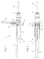
- FIG. 1 to Fig. 4 show a handle 1 for a medical instrument with a closable via a cover 2 handle housing 3, wherein the handle housing 3 consists essentially of a base part 4 and the cover 2.
- two suction and flushing hoses 5 can be connected via an adapter 6 to two hose connecting pieces 7 in the handle housing 3, but also handles 1 with only one suction and / or flushing hose 5 or more than two hoses 5 executable.
- the distal end of each suction and / or irrigation tube 5 is fixed to an adapter 6, which in turn can be connected to the associated hose connection piece 7.
- the use of the adapter 6 for fixing a suction and flushing hose 5 on the associated hose connection piece 7 has the advantage that the connection of the suction and flushing hose 5 on the hose connection piece 7 indirectly, namely via the intermediate adapter 6, so that the hose material spared when connecting can be and it does not require a respective expansion and compression of the tubing when pushing and pressing on the hose connection piece 7.
- Rinsing fluid is conducted to the surgical area via the suction and irrigation tubes 5 and sucked out of the surgical area again in order to ensure a good view of the operating area for the surgeon.
- the handle 1 For metering the suction and / or flushing power to be accomplished via the hoses 5, the handle 1 also has two buttons 8 arranged on the base part 4, via which the flow through the hoses 5 can be throttled.
- the buttons 8 In the illustrations according to Fig. 1, 2 and 4 is only one button 8 to recognize, since the buttons are arranged directly behind each other in these side views.
- the number of buttons 8 but usually corresponds to the number of arranged in the handle 1 tubes. 5
- the handle 1 has a coupling element 9 in the form of a clamping screw, via which, for example, an instrument shaft 10 (shown in dashed lines) can be fixed to the handle 1.
- the adapter 6 in the embodiment shown here for coupling two tubes 5 with two hose connection piece 7 H-shaped so that the tubes 5 are pushed onto the proximal free ends of the longitudinal leg 6a of the H-shaped adapter 6, whereas the distal-side free ends of the longitudinal leg 6a of the H-shaped adapter 6 for coupling with the two hose connection piece 7 serve.
- the adapter 6 is U-shaped so that the tubes 5 are pushed onto the proximal free ends of the longitudinal leg 6a of the U-shaped adapter 6, whereas distally, the two longitudinal legs 6a of the U-shaped adapter 6 interconnecting connecting web 6b for coupling with the two hose connection piece 7 is used.
- connection of the hoses 5 to the hose connector 7 of the handle 1 is done as follows:
- a locking mechanism 11 is actuated on the handle housing 3 in order to unlock the cover 2 from its latching on the base part 4.
- the lid 2 can be pivoted about a pivot axis 12 by about 90 ° relative to the base part 4 in the open position, as in Fig. 1 is shown.
- the two tubes 5 are pushed from the same side as far as possible on the free ends of the longitudinal leg 6a of the H or U-shaped adapter 6.
- This thus connected to the adapter 6 hose set is now inserted into the base part 4 of the handle 1, that not equipped with the hoses 5 free ends of the longitudinal leg 6a of the H-shaped adapter 6 abut the hose connection piece 7, as shown in the plan view Fig. 2 can be seen.
- a stop 13 is formed on the inside of the handle housing 3 facing inside of the lid 2, which in the illustrated and out Fig. 1 . 3 . 4 and 5 recognizable embodiment is designed as a narrow web.
- This stopper 13 is positioned on the inside of the lid 2 so that it closes when the lid is closed, as shown in FIG Fig. 3, 4 and 5 is shown, against which the two longitudinal legs 6a of the H or U-shaped adapter 6 interconnecting connecting web 6b starts and so presses the adapter 6 distally against the hose connection piece 7.
- the stop 13 thus causes automatically when closing the lid 2 of the equipped with the tubes 5 adapter 6 is pressed in fluid-tight contact with the hose connection piece 7. How out Fig. 4 and 5 can be seen, the stop 13 is at the lid 2 closed at the connecting web 6b of the adapter 6 and thus ensures that the adapter 6 can not be moved by tensile load in the proximal direction of the hoses 5 from its fluid-tight contact with the hose connection piece 7 away.
- sealing elements 14 in particular in the form of O-ring seals, are provided at the free ends of the longitudinal legs 6a of the H-shaped adapter 6 for sealing against the hose connecting pieces 7. set, which are sealingly deformed when pressing the adapter 6 against the hose connection piece 7.
- stop 13 on the base part 4 in such a way that it starts against the adapter 6 when the lid 2 is closed and presses the adapter 6 sealingly against the hose connecting pieces 7.
- Such a trained handle is characterized in that it is easy to assemble and clean with a simple structure and automatically ensures each time the cover 2 of the handle housing 3, that the hoses 5 are connected via the adapter 6 fluid-tight to the hose connection piece 7.
Abstract
Description
Die Erfindung betrifft einen Handgriff für ein medizinisches Instrument mit einem über einen Deckel verschließbaren Griffgehäuse und mit mindestens einem im Griffgehäuse an einen Schlauchanschlussstutzen anschließbaren Saug- und/oder Spülschlauch.The invention relates to a handle for a medical instrument with a closable via a cover handle housing and with at least one connectable in the handle housing to a hose connection piece suction and / or rinsing hose.
Um insbesondere bei endoskopischen Operationen dem Operateur einen guten Blick auf das Operationsgebiet zu gewähren, ist es häufig erforderlich, das Operationsgebiet mit einer Spülflüssigkeit zu reinigen und die Spülflüssigkeit sowie austretendes Blut aus dem Operationsgebiet abzusaugen. Zu diesem Zweck sind entsprechende medizinische Instrumente mit Saug- und/oder Spülschläuchen ausgestattet, die über die Handhabe des jeweiligen Instruments bedienbar sind.In order to give the surgeon a good view of the operating area, in particular during endoscopic operations, it is often necessary to clean the surgical area with a rinsing fluid and to aspirate the rinsing fluid and escaping blood from the operating area. For this purpose, appropriate medical instruments are equipped with suction and / or irrigation tubes, which can be operated via the handle of the respective instrument.
Bei den aus der Praxis bekannten medizinischen Instrumenten besteht das Problem, dass diese im Bereich des die Schlauchanschlussstutzen aufweisenden Handgriffs schlecht zu reinigen ist und darüber hinaus eine nur unzureichende Fluiddichtigkeit gegen Leckagen gewährleisten.In the medical instruments known from practice, the problem is that it is difficult to clean in the region of the hose connection piece having handle and also ensure only insufficient fluid tightness against leaks.
Ein gattungsgemäßer Handgriff ist beispielsweise aus der
Davon ausgehend liegt der Erfindung die Aufgabe zugrunde, einen Handgriff der eingangs genannten Art zu schaffen, der bei einfachem Aufbau eine zuverlässige fluiddichte Verbindung von Schlauch und Schlauchanschlussstutzen bei gleichzeitiger Schonung des Schlauchmaterials gewährleistet.On this basis the invention has for its object to provide a handle of the type mentioned which ensures a reliable fluid-tight connection of the hose and hose connection pieces with simultaneous protection of the tubing in a simple construction.
Die Lösung dieser Aufgabenstellung ist erfindungsgemäß dadurch gekennzeichnet, dass jeder Saug- und/oder Spülschlauch über einen Adapter an den zugehörigen Schlauchanschlussstutzen anschließbar ist und, dass der Adapter beim Schließen des Griffgehäuses über einen am Deckel und/oder am Basisteil des Griffgehäuses angeordneten Anschlag gegen den Schlauchanschlussstutzen anpressbar ist.The solution to this problem is inventively characterized in that each suction and / or flushing hose is connected via an adapter to the associated hose connection piece and that the adapter when closing the handle housing via a arranged on the lid and / or on the base part of the handle housing stop against the Hose connection piece can be pressed on.
Durch die erfindungsgemäße Verwendung eines Adapters zum Anschließen eines jeden Saug- und/oder Spülschlauches an seinen zugehörigen Schlauchanschlussstutzen werden die Schlauchenden geschont, da das eigentliche Kontaktieren mit den Schlauchanschlussstutzen über den zwischengeschalteten Adapter erfolgt. Durch die Ausbildung eines Anschlags am Deckel und/oder am Griffgehäuse, der beim Schließen des Griffgehäuses gegen den Adapter anläuft wird sichergestellt, dass automatisch bei jedem Schließen des Griffgehäuses der Adapter über dem Anschlag abdichtend und mit stets gleichem Druck gegen den zugehörigen Schlauchanschlussstutzen angepresst wird.The inventive use of an adapter for connecting each suction and / or irrigation hose to its associated hose connection piece, the hose ends are protected, since the actual contacting is done with the hose connection piece via the intermediate adapter. The formation of a stop on the cover and / or on the handle housing, which starts when closing the handle housing against the adapter ensures that automatically with each closing of the handle housing, the adapter is pressed over the stop sealingly and always with the same pressure against the associated hose connection piece.
Gemäß einer bevorzugten Ausführungsform der Erfindung wird vorgeschlagen, dass der Anschlag als am Deckel angeformter, nach innen weisender Steg ausgebildet ist. Das Anordnen des Anschlags am Gehäusedeckel stellt eine besonders einfach zu fertigende und problemlos zu handhabende Ausgestaltungsform dar.According to a preferred embodiment of the invention it is proposed that the stop is formed as integrally formed on the cover, inwardly facing web. Placing the stop on the housing cover is a particularly easy to manufacture and easy to handle embodiment.
Alternativ zu der Anordnung des Anschlags am Deckel des Handgriffs ist es selbstverständlich auch möglich, den Anschlag am unteren Teil des Griffgehäuses so anzuordnen, dass der Anschlag beim Schließen des Deckels gegen den Adapter gedrückt wird.As an alternative to the arrangement of the stop on the cover of the handle, it is of course also possible to arrange the stop on the lower part of the handle housing so that the stop is pressed against the adapter when closing the lid.
Mit einer ersten praktischen Ausgestaltungsform der Erfindung wird vorgeschlagen, dass der Adapter zum Anschließen von zwei Schläuchen an zwei Schlauchanschlussstutzen H-förmig ausgebildet ist.With a first practical embodiment of the invention it is proposed that the adapter for connecting two hoses to two hose connection pieces is H-shaped.
Bei einer zweiten erfindungsgemäßen Ausführungsform wird vorgeschlagen, dass der Adapter zum Anschließen von zwei Schläuchen an zwei Schlauchanschlussstutzen U-förmig ausgebildet ist.In a second embodiment according to the invention, it is proposed that the adapter is designed to be U-shaped for connecting two hoses to two hose connection stubs.
Schließlich wird mit der Erfindung vorgeschlagen, dass am Adapter und/oder am Schlauchanschlussstutzen mindestens ein Dichtungselement, insbesondere eine O-Ring-Dichtung, festlegbar ist, um die fluiddichte Anlage des Adapters am zugehörigen Schlauchanschlussstutzen zu verbessern. Beim Anpressen des Adapters gegen den Schlauchanschlussstutzen wird das Dichtungselement abdichtend verformt.Finally, it is proposed with the invention that at least one sealing element, in particular an O-ring seal, can be fixed to the adapter and / or the hose connecting piece, in order to improve the fluid-tight contact of the adapter with the associated hose connection piece. When pressing the adapter against the hose connection piece, the sealing element is sealingly deformed.
Weiterhin wird mit der Erfindung vorgeschlagen, dass zum Abdichten gegenüber dem Schlauchanschlussstutzen der Adapter aus einem Dichtungsmaterial, insbesondere Silikon, besteht.Furthermore, it is proposed with the invention that for sealing against the hose connection piece, the adapter consists of a sealing material, in particular silicone.
Weitere Merkmale und Vorteile der Erfindung ergeben sich anhand der zugehörigen Zeichnung, in der ein Ausführungsbeispiel eines erfindungsgemäßen Handgriffs für ein medizinisches Instrument nur beispielhaft dargestellt ist, ohne die Erfindung auf dieses Ausführungsbeispiel zu beschränken. In der Zeichnung zeigt:
- Fig. 1
- eine teilweise geschnittene Seitenansicht eines erfindungsgemäßen Handgriffs mit geöffnetem Deckel;
- Fig. 2
- eine Draufsicht auf den Handgriff gemäß
Fig. 1 ; jedoch ohne Deckel; - Fig. 3
- eine Seitenansicht gemäß
Fig. 1 mit teilweise geschlossenem Deckel; - Fig. 4
- eine Seitenansicht gemäß
Fig. 3 mit geschlossenem Deckel; - Fig. 5
- eine vergrößerte Ansicht des Details V gemäß
Fig. 4 und - Fig. 6
- eine vergrößerte schematische Ansicht einer zweiten Ausführungsform eines Adapters.
- Fig. 1
- a partially sectioned side view of a handle according to the invention with the lid open;
- Fig. 2
- a plan view of the handle according to
Fig. 1 ; but without lid; - Fig. 3
- a side view according to
Fig. 1 with partially closed lid; - Fig. 4
- a side view according to
Fig. 3 with lid closed; - Fig. 5
- an enlarged view of the detail V according to
Fig. 4 and - Fig. 6
- an enlarged schematic view of a second embodiment of an adapter.
Die Abbildungen
Bei der dargestellten Ausführungsform des Handgriffs 1 sind im Griffgehäuse 3 zwei Saug- und Spülschläuche 5 über einen Adapter 6 an zwei Schlauchanschlussstutzen 7 anschließbar, jedoch sind auch Handgriffe 1 mit nur einem Saug- und/oder Spülschlauch 5 oder mehr als zwei Schläuchen 5 ausführbar. In jedem Fall ist aber das distalseitige Ende eines jeden Saug- und/oder Spülschlauches 5 an einem Adapter 6 festgelegt, der seinerseits an die zugehörigen Schlauchanschlussstutzen 7 anschließbar ist.In the illustrated embodiment of the
Die Verwendung des Adapters 6 zum Festlegen eines Saug- und Spülschlauches 5 am zugehörigen Schlauchanschlussstutzen 7 hat den Vorteil, dass das Anschließen des Saug- und Spülschlauches 5 am Schlauchanschlussstutzen 7 indirekt, nämlich über den zwischengeschalteten Adapter 6 erfolgt, so dass das Schlauchmaterial beim Anschließen geschont werden kann und es nicht einer jeweiligen Dehnung und Stauchung des Schlauchmaterials beim Aufschieben und Andrücken auf die Schlauchanschlussstutzen 7 bedarf.The use of the
Über die Saug- und Spülschläuche 5 wird Spülflüssigkeit zum Operationsgebiet geleitet und wieder aus dem Operationsgebiet abgesaugt, um dem Operateur eine gute Sicht auf das Operationsgebiet zu gewährleisten.Rinsing fluid is conducted to the surgical area via the suction and
Zur Dosierung der über die Schläuche 5 zu bewerkstelligenden Saug- und/oder Spülleistung weist der Handgriff 1 weiterhin zwei am Basisteil 4 angeordnete Taster 8 auf, über die der Durchfluss durch die Schläuche 5 drosselbar ist. In den Darstellungen gemäß
Am distalen Ende weist der Handgriff 1 eine Kupplungselement 9 in Form einer Klemmschraube auf, über das beispielsweise ein Instrumentenschaft 10 (gestrichelt dargestellt) am Handgriff 1 festlegbar ist.At the distal end, the
Wie aus
Bei der in
Das Anschließen der Schläuche 5 an die Schlauchanschlussstutzen 7 des Handgriffs 1 geschieht wie folgt:The connection of the
Im ersten Arbeitsschritt wird ein Sperrmechanismus 11 am Griffgehäuse 3 betätigt, um den Deckel 2 aus seiner Verrastung am Basisteil 4 zu entriegeln. Danach lässt sich der Deckel 2 um eine Schwenkachse 12 um etwa 90° gegenüber dem Basisteil 4 in die geöffnete Position verschwenken, wie sie in
Nachfolgend werden die beiden Schläuche 5 von derselben Seite her so weit wie möglich auf die freien Enden der Längsschenkel 6a des H- oder U-förmigen Adapters 6 aufgeschoben. Dieses solchermaßen mit dem Adapter 6 verbundene Schlauchset wird jetzt so in das Basisteil 4 des Handgriffs 1 eingelegt, dass die nicht mit den Schläuchen 5 bestückten freien Enden der Längsschenkel 6a des H-förmigen Adapters 6 an den Schlauchanschlussstutzen 7 anliegen, wie dies der Draufsicht gemäß
Entscheidend für den fluiddichten Anschluss des Adapters 6 an die Schlauchanschlussstutzen 7 ist, dass der Adapter 6 ausreichend tief in die Schlauchanschlussstutzen 7 eingeschoben wird.Decisive for the fluid-tight connection of the
Zu diesem Zweck ist auf der dem Innenraum des Griffgehäuses 3 zugewandten Innenseite des Deckels 2 ein Anschlag 13 angeformt, der bei der dargestellten und aus
Dieser Anschlag 13 ist so an der Innenseite des Deckels 2 positioniert, dass er beim Schließen des Deckels, wie dies in
Der Anschlag 13 bewirkt somit, dass automatisch beim Schließen des Deckels 2 der mit den Schläuchen 5 bestückte Adapter 6 in fluiddichte Anlage gegen die Schlauchanschlussstutzen 7 gepresst wird. Wie aus
Um die fluiddichte Anlage des Adapters 6 an den Schlauchanschlussstutzen 7 noch weiter zu verbessern, sind an den freien Enden der Längsschenkel 6a des H-förmigen Adapters 6 zum Abdichten gegenüber den Schlauchanschlussstutzen 7 Dichtungselemente 14, insbesondere in der Form von O-Ring-Dichtungen, festgelegt, die beim Anpressen des Adapters 6 gegen die Schlauchanschlussstutzen 7 abdichtend verformt werden.In order to further improve the fluid-tight contact of the
Ebenso ist es möglich, die Dichtungselemente 14 auf Seiten der Schlauchanschlussstutzen 7 anzuordnen, um eine fluiddichte Anlage des Adapters 6 an den Schlauchanschlussstutzen 7 zu gewährleisten.It is also possible to arrange the sealing
Alternativ zu der dargestellten Ausführungsform ist es selbstverständlich auch möglich, den Anschlag 13 am Basisteil 4 so anzuordnen, dass dieser beim Schließen des Deckels 2 gegen den Adapter 6 anläuft und den Adapter 6 abdichtend gegen die Schlauchanschlussstutzen 7 presst.As an alternative to the illustrated embodiment, it is of course also possible to arrange the
Ein solchermaßen ausgebildeter Handgriff zeichnet sich dadurch aus, dass er bei einfachem Aufbau leicht zu montieren und zu reinigen ist und bei jedem Schließen des Deckels 2 des Griffgehäuses 3 automatisch sicherstellt, dass die Schläuche 5 über den Adapter 6 fluiddicht an den Schlauchanschlussstutzen 7 angeschlossen sind.Such a trained handle is characterized in that it is easy to assemble and clean with a simple structure and automatically ensures each time the
- 11
- Handgriffhandle
- 22
- Deckelcover
- 33
- Griffgehäusehandle housing
- 44
- Basisteilbase
- 55
- Saug- und Spülschlauch / SchlauchSuction and irrigation hose / hose
- 66
- Adapteradapter
- 6a6a
- Längsschenkellongitudinal leg
- 6b6b
- Verbindungsstegconnecting web
- 77
- SchlauchanschlussstutzenHose connectors
- 88th
- Tasterbutton
- 99
- Kupplungselementcoupling member
- 1010
- Instrumentenschaftinstrument shaft
- 1111
- Sperrmechanismuslocking mechanism
- 1212
- Schwenkachseswivel axis
- 1313
- Anschlagattack
- 1414
- Dichtungselementsealing element
Claims (7)
dadurch gekennzeichnet,
dass jeder Saug- und/oder Spülschlauch (5) über einen Adapter (6) an den zugehörigen Schlauchanschlussstutzen (7) anschließbar ist und, dass der Adapter (6) beim Schließen des Griffgehäuses (3) über einen am Deckel (2) und/oder am Basisteil (4) des Griffgehäuses (3) angeordneten Anschlag (13) gegen den Schlauchanschlussstutzen (7) anpressbar ist.Handle for a medical instrument with a cover (2) closable handle housing (3) and at least one in the handle housing (3) to a hose connection piece (7) connectable suction and / or rinsing hose (5),
characterized,
in that each suction and / or rinsing hose (5) can be connected to the associated hose connecting piece (7) via an adapter (6) and that the adapter (6) is closed by closing the handle housing (3) via a cover (2) and / or on the base part (4) of the handle housing (3) arranged stop (13) against the hose connection piece (7) can be pressed.
Applications Claiming Priority (1)
| Application Number | Priority Date | Filing Date | Title |
|---|---|---|---|
| DE202008005899 | 2008-04-29 |
Publications (2)
| Publication Number | Publication Date |
|---|---|
| EP2113265A1 true EP2113265A1 (en) | 2009-11-04 |
| EP2113265B1 EP2113265B1 (en) | 2011-11-02 |
Family
ID=40801910
Family Applications (1)
| Application Number | Title | Priority Date | Filing Date |
|---|---|---|---|
| EP09004828A Active EP2113265B1 (en) | 2008-04-29 | 2009-04-01 | Handle for a medical instrument |
Country Status (3)
| Country | Link |
|---|---|
| US (1) | US8926549B2 (en) |
| EP (1) | EP2113265B1 (en) |
| AT (1) | ATE531402T1 (en) |
Cited By (1)
| Publication number | Priority date | Publication date | Assignee | Title |
|---|---|---|---|---|
| DE102010050352A1 (en) * | 2010-11-05 | 2012-05-10 | Hopp-Elektronik Gmbh & Co. Kg | Surgical instrument |
Families Citing this family (5)
| Publication number | Priority date | Publication date | Assignee | Title |
|---|---|---|---|---|
| US9364651B2 (en) | 2010-02-23 | 2016-06-14 | Smiths Medical Asd, Inc. | Adapter with special fitting |
| US8876798B2 (en) * | 2010-02-23 | 2014-11-04 | Smiths Medical Asd, Inc. | Catheter adapter |
| US10737087B2 (en) | 2012-04-17 | 2020-08-11 | Smiths Medical Asd, Inc. | Filling fitting |
| GB2564448A (en) * | 2017-07-10 | 2019-01-16 | Conceptomed As | Fluid Transfer connectors |
| JP7082815B2 (en) * | 2018-12-19 | 2022-06-09 | 株式会社ユニシス | Catheter connector |
Citations (3)
| Publication number | Priority date | Publication date | Assignee | Title |
|---|---|---|---|---|
| US4723948A (en) * | 1986-11-12 | 1988-02-09 | Pharmacia Nu Tech | Catheter attachment system |
| DE19647816A1 (en) * | 1996-11-19 | 1998-05-28 | Wolf Gmbh Richard | Medical device to supply and collect rinsing fluid for body cavity |
| WO2009000439A1 (en) * | 2007-06-22 | 2008-12-31 | Pajunk Gmbh & Co. Kg Besitzverwaltung | Clamp adapter for a catheter |
Family Cites Families (3)
| Publication number | Priority date | Publication date | Assignee | Title |
|---|---|---|---|---|
| US5147292A (en) * | 1991-02-05 | 1992-09-15 | C. R. Bard, Inc. | Control handle with locking means for surgical irrigation |
| US5230704A (en) | 1992-06-26 | 1993-07-27 | Biomedical Dynamics Corporation | Suction/irrigation instrument having reusable handle with disposable fluid path |
| US5792098A (en) * | 1996-06-19 | 1998-08-11 | C. R. Bard, Inc. | Suction and irrigation handpiece and tip with detachable tube |
-
2009
- 2009-04-01 AT AT09004828T patent/ATE531402T1/en active
- 2009-04-01 EP EP09004828A patent/EP2113265B1/en active Active
- 2009-04-29 US US12/432,362 patent/US8926549B2/en active Active
Patent Citations (4)
| Publication number | Priority date | Publication date | Assignee | Title |
|---|---|---|---|---|
| US4723948A (en) * | 1986-11-12 | 1988-02-09 | Pharmacia Nu Tech | Catheter attachment system |
| DE19647816A1 (en) * | 1996-11-19 | 1998-05-28 | Wolf Gmbh Richard | Medical device to supply and collect rinsing fluid for body cavity |
| DE19647816C2 (en) | 1996-11-19 | 2003-05-15 | Wolf Gmbh Richard | Medical instrument for supplying and removing rinsing liquid |
| WO2009000439A1 (en) * | 2007-06-22 | 2008-12-31 | Pajunk Gmbh & Co. Kg Besitzverwaltung | Clamp adapter for a catheter |
Cited By (1)
| Publication number | Priority date | Publication date | Assignee | Title |
|---|---|---|---|---|
| DE102010050352A1 (en) * | 2010-11-05 | 2012-05-10 | Hopp-Elektronik Gmbh & Co. Kg | Surgical instrument |
Also Published As
| Publication number | Publication date |
|---|---|
| ATE531402T1 (en) | 2011-11-15 |
| US8926549B2 (en) | 2015-01-06 |
| EP2113265B1 (en) | 2011-11-02 |
| US20090270842A1 (en) | 2009-10-29 |
Similar Documents
| Publication | Publication Date | Title |
|---|---|---|
| EP2113265B1 (en) | Handle for a medical instrument | |
| EP3266075B1 (en) | Medical plug-in and snap-in connector for establishing a fluid connection between two systems | |
| EP1620016B1 (en) | Coaxial cannula provided with a sealing element | |
| EP2964992B1 (en) | Plug-in connection for two pipes and method for assembling the plug-in connection | |
| EP1761289A1 (en) | Milk extraction device | |
| DE10009020A1 (en) | Hysteroscope | |
| EP1214002A1 (en) | Medical instrument | |
| EP2232108B1 (en) | Closure device for tightly closing a filling and emptying system of railway tank cars or transportation tanks | |
| EP1775507B1 (en) | Fitting for pipes | |
| DE10160703C1 (en) | Reservoir for blood sampling apparatus has piston which slides in casing and is operated by ring or knob, piston being biased to position in which chamber in casing has minimal volume | |
| EP3730705A1 (en) | Sanitary valve | |
| DE102005004147A1 (en) | Handling device for detaching/connecting flexible tubes and hoses on a plug-in connection device has a release element triggered so as to disengage an anchored tube | |
| AT501505A1 (en) | CONNECTOR WITH CONNECTING PLUGS AND CABLE | |
| EP2604171B1 (en) | Handle for a medical instrument | |
| DE202008006485U1 (en) | Suction flush handle with a hose set | |
| EP2584242A1 (en) | Releasable plug connector | |
| DE10236059A1 (en) | Quick coupler for pipes, is made up of two sections, one of which contains valve piston which closes it until sections are connected, when contact in second section fits into recess in piston and opens it | |
| EP2526992B1 (en) | Catheter valve | |
| DE102007019627B3 (en) | measuring device | |
| DE102011112050B4 (en) | Modular compression connector and system for this | |
| DE102008016015B3 (en) | Device for connecting flexible pressurizing medium line with fluid connector of pressurizing medium assembly e.g. cylinder, has connection unit with fastening part that is insertable into or over end of flexible pressurizing medium line | |
| EP1584348B1 (en) | Tube connector for connecting measuring probes for medical surveillance devices | |
| EP2489799A1 (en) | Waste water hoisting facility | |
| WO2011006464A1 (en) | Non-return valve | |
| DE202006014736U1 (en) | Pipe connection for sewers in caravans, campers or the like. |
Legal Events
| Date | Code | Title | Description |
|---|---|---|---|
| PUAI | Public reference made under article 153(3) epc to a published international application that has entered the european phase |
Free format text: ORIGINAL CODE: 0009012 |
|
| AK | Designated contracting states |
Kind code of ref document: A1 Designated state(s): AT BE BG CH CY CZ DE DK EE ES FI FR GB GR HR HU IE IS IT LI LT LU LV MC MK MT NL NO PL PT RO SE SI SK TR |
|
| 17P | Request for examination filed |
Effective date: 20100430 |
|
| 17Q | First examination report despatched |
Effective date: 20100830 |
|
| GRAP | Despatch of communication of intention to grant a patent |
Free format text: ORIGINAL CODE: EPIDOSNIGR1 |
|
| GRAS | Grant fee paid |
Free format text: ORIGINAL CODE: EPIDOSNIGR3 |
|
| GRAA | (expected) grant |
Free format text: ORIGINAL CODE: 0009210 |
|
| AK | Designated contracting states |
Kind code of ref document: B1 Designated state(s): AT BE BG CH CY CZ DE DK EE ES FI FR GB GR HR HU IE IS IT LI LT LU LV MC MK MT NL NO PL PT RO SE SI SK TR |
|
| REG | Reference to a national code |
Ref country code: GB Ref legal event code: FG4D Free format text: NOT ENGLISH |
|
| REG | Reference to a national code |
Ref country code: CH Ref legal event code: EP |
|
| REG | Reference to a national code |
Ref country code: IE Ref legal event code: FG4D |
|
| REG | Reference to a national code |
Ref country code: DE Ref legal event code: R096 Ref document number: 502009001763 Country of ref document: DE Effective date: 20111229 |
|
| REG | Reference to a national code |
Ref country code: NL Ref legal event code: VDEP Effective date: 20111102 |
|
| LTIE | Lt: invalidation of european patent or patent extension |
Effective date: 20111102 |
|
| PG25 | Lapsed in a contracting state [announced via postgrant information from national office to epo] |
Ref country code: NO Free format text: LAPSE BECAUSE OF FAILURE TO SUBMIT A TRANSLATION OF THE DESCRIPTION OR TO PAY THE FEE WITHIN THE PRESCRIBED TIME-LIMIT Effective date: 20120202 Ref country code: IS Free format text: LAPSE BECAUSE OF FAILURE TO SUBMIT A TRANSLATION OF THE DESCRIPTION OR TO PAY THE FEE WITHIN THE PRESCRIBED TIME-LIMIT Effective date: 20120302 Ref country code: LT Free format text: LAPSE BECAUSE OF FAILURE TO SUBMIT A TRANSLATION OF THE DESCRIPTION OR TO PAY THE FEE WITHIN THE PRESCRIBED TIME-LIMIT Effective date: 20111102 |
|
| PG25 | Lapsed in a contracting state [announced via postgrant information from national office to epo] |
Ref country code: PT Free format text: LAPSE BECAUSE OF FAILURE TO SUBMIT A TRANSLATION OF THE DESCRIPTION OR TO PAY THE FEE WITHIN THE PRESCRIBED TIME-LIMIT Effective date: 20120302 Ref country code: PL Free format text: LAPSE BECAUSE OF FAILURE TO SUBMIT A TRANSLATION OF THE DESCRIPTION OR TO PAY THE FEE WITHIN THE PRESCRIBED TIME-LIMIT Effective date: 20111102 Ref country code: HR Free format text: LAPSE BECAUSE OF FAILURE TO SUBMIT A TRANSLATION OF THE DESCRIPTION OR TO PAY THE FEE WITHIN THE PRESCRIBED TIME-LIMIT Effective date: 20111102 Ref country code: NL Free format text: LAPSE BECAUSE OF FAILURE TO SUBMIT A TRANSLATION OF THE DESCRIPTION OR TO PAY THE FEE WITHIN THE PRESCRIBED TIME-LIMIT Effective date: 20111102 Ref country code: LV Free format text: LAPSE BECAUSE OF FAILURE TO SUBMIT A TRANSLATION OF THE DESCRIPTION OR TO PAY THE FEE WITHIN THE PRESCRIBED TIME-LIMIT Effective date: 20111102 Ref country code: SE Free format text: LAPSE BECAUSE OF FAILURE TO SUBMIT A TRANSLATION OF THE DESCRIPTION OR TO PAY THE FEE WITHIN THE PRESCRIBED TIME-LIMIT Effective date: 20111102 Ref country code: SI Free format text: LAPSE BECAUSE OF FAILURE TO SUBMIT A TRANSLATION OF THE DESCRIPTION OR TO PAY THE FEE WITHIN THE PRESCRIBED TIME-LIMIT Effective date: 20111102 Ref country code: GR Free format text: LAPSE BECAUSE OF FAILURE TO SUBMIT A TRANSLATION OF THE DESCRIPTION OR TO PAY THE FEE WITHIN THE PRESCRIBED TIME-LIMIT Effective date: 20120203 |
|
| REG | Reference to a national code |
Ref country code: IE Ref legal event code: FD4D |
|
| PG25 | Lapsed in a contracting state [announced via postgrant information from national office to epo] |
Ref country code: CY Free format text: LAPSE BECAUSE OF FAILURE TO SUBMIT A TRANSLATION OF THE DESCRIPTION OR TO PAY THE FEE WITHIN THE PRESCRIBED TIME-LIMIT Effective date: 20111102 |
|
| PG25 | Lapsed in a contracting state [announced via postgrant information from national office to epo] |
Ref country code: SK Free format text: LAPSE BECAUSE OF FAILURE TO SUBMIT A TRANSLATION OF THE DESCRIPTION OR TO PAY THE FEE WITHIN THE PRESCRIBED TIME-LIMIT Effective date: 20111102 Ref country code: DK Free format text: LAPSE BECAUSE OF FAILURE TO SUBMIT A TRANSLATION OF THE DESCRIPTION OR TO PAY THE FEE WITHIN THE PRESCRIBED TIME-LIMIT Effective date: 20111102 Ref country code: BG Free format text: LAPSE BECAUSE OF FAILURE TO SUBMIT A TRANSLATION OF THE DESCRIPTION OR TO PAY THE FEE WITHIN THE PRESCRIBED TIME-LIMIT Effective date: 20120202 Ref country code: IE Free format text: LAPSE BECAUSE OF FAILURE TO SUBMIT A TRANSLATION OF THE DESCRIPTION OR TO PAY THE FEE WITHIN THE PRESCRIBED TIME-LIMIT Effective date: 20111102 Ref country code: CZ Free format text: LAPSE BECAUSE OF FAILURE TO SUBMIT A TRANSLATION OF THE DESCRIPTION OR TO PAY THE FEE WITHIN THE PRESCRIBED TIME-LIMIT Effective date: 20111102 Ref country code: EE Free format text: LAPSE BECAUSE OF FAILURE TO SUBMIT A TRANSLATION OF THE DESCRIPTION OR TO PAY THE FEE WITHIN THE PRESCRIBED TIME-LIMIT Effective date: 20111102 |
|
| PG25 | Lapsed in a contracting state [announced via postgrant information from national office to epo] |
Ref country code: RO Free format text: LAPSE BECAUSE OF FAILURE TO SUBMIT A TRANSLATION OF THE DESCRIPTION OR TO PAY THE FEE WITHIN THE PRESCRIBED TIME-LIMIT Effective date: 20111102 |
|
| PLBE | No opposition filed within time limit |
Free format text: ORIGINAL CODE: 0009261 |
|
| STAA | Information on the status of an ep patent application or granted ep patent |
Free format text: STATUS: NO OPPOSITION FILED WITHIN TIME LIMIT |
|
| 26N | No opposition filed |
Effective date: 20120803 |
|
| BERE | Be: lapsed |
Owner name: KARL STORZ G.M.B.H. & CO. KG Effective date: 20120430 |
|
| REG | Reference to a national code |
Ref country code: DE Ref legal event code: R097 Ref document number: 502009001763 Country of ref document: DE Effective date: 20120803 |
|
| PG25 | Lapsed in a contracting state [announced via postgrant information from national office to epo] |
Ref country code: MC Free format text: LAPSE BECAUSE OF NON-PAYMENT OF DUE FEES Effective date: 20120430 |
|
| PG25 | Lapsed in a contracting state [announced via postgrant information from national office to epo] |
Ref country code: BE Free format text: LAPSE BECAUSE OF NON-PAYMENT OF DUE FEES Effective date: 20120430 |
|
| PG25 | Lapsed in a contracting state [announced via postgrant information from national office to epo] |
Ref country code: MK Free format text: LAPSE BECAUSE OF FAILURE TO SUBMIT A TRANSLATION OF THE DESCRIPTION OR TO PAY THE FEE WITHIN THE PRESCRIBED TIME-LIMIT Effective date: 20111102 |
|
| PG25 | Lapsed in a contracting state [announced via postgrant information from national office to epo] |
Ref country code: ES Free format text: LAPSE BECAUSE OF FAILURE TO SUBMIT A TRANSLATION OF THE DESCRIPTION OR TO PAY THE FEE WITHIN THE PRESCRIBED TIME-LIMIT Effective date: 20120213 |
|
| PG25 | Lapsed in a contracting state [announced via postgrant information from national office to epo] |
Ref country code: FI Free format text: LAPSE BECAUSE OF FAILURE TO SUBMIT A TRANSLATION OF THE DESCRIPTION OR TO PAY THE FEE WITHIN THE PRESCRIBED TIME-LIMIT Effective date: 20111102 |
|
| PG25 | Lapsed in a contracting state [announced via postgrant information from national office to epo] |
Ref country code: MT Free format text: LAPSE BECAUSE OF FAILURE TO SUBMIT A TRANSLATION OF THE DESCRIPTION OR TO PAY THE FEE WITHIN THE PRESCRIBED TIME-LIMIT Effective date: 20111102 |
|
| REG | Reference to a national code |
Ref country code: CH Ref legal event code: PL |
|
| PG25 | Lapsed in a contracting state [announced via postgrant information from national office to epo] |
Ref country code: CH Free format text: LAPSE BECAUSE OF NON-PAYMENT OF DUE FEES Effective date: 20130430 Ref country code: LI Free format text: LAPSE BECAUSE OF NON-PAYMENT OF DUE FEES Effective date: 20130430 |
|
| PG25 | Lapsed in a contracting state [announced via postgrant information from national office to epo] |
Ref country code: TR Free format text: LAPSE BECAUSE OF FAILURE TO SUBMIT A TRANSLATION OF THE DESCRIPTION OR TO PAY THE FEE WITHIN THE PRESCRIBED TIME-LIMIT Effective date: 20111102 |
|
| PG25 | Lapsed in a contracting state [announced via postgrant information from national office to epo] |
Ref country code: LU Free format text: LAPSE BECAUSE OF NON-PAYMENT OF DUE FEES Effective date: 20120401 |
|
| PG25 | Lapsed in a contracting state [announced via postgrant information from national office to epo] |
Ref country code: HU Free format text: LAPSE BECAUSE OF FAILURE TO SUBMIT A TRANSLATION OF THE DESCRIPTION OR TO PAY THE FEE WITHIN THE PRESCRIBED TIME-LIMIT Effective date: 20090401 |
|
| REG | Reference to a national code |
Ref country code: AT Ref legal event code: MM01 Ref document number: 531402 Country of ref document: AT Kind code of ref document: T Effective date: 20140401 |
|
| PG25 | Lapsed in a contracting state [announced via postgrant information from national office to epo] |
Ref country code: AT Free format text: LAPSE BECAUSE OF NON-PAYMENT OF DUE FEES Effective date: 20140401 |
|
| REG | Reference to a national code |
Ref country code: FR Ref legal event code: PLFP Year of fee payment: 8 |
|
| REG | Reference to a national code |
Ref country code: FR Ref legal event code: PLFP Year of fee payment: 9 |
|
| REG | Reference to a national code |
Ref country code: DE Ref legal event code: R081 Ref document number: 502009001763 Country of ref document: DE Owner name: KARL STORZ SE & CO. KG INTELLECTUAL PROPERTY, DE Free format text: FORMER OWNER: KARL STORZ GMBH & CO. KG, 78532 TUTTLINGEN, DE Ref country code: DE Ref legal event code: R082 Ref document number: 502009001763 Country of ref document: DE Representative=s name: HOFMEISTER, FRANK, DIPL.-ING., DE Ref country code: DE Ref legal event code: R081 Ref document number: 502009001763 Country of ref document: DE Owner name: KARL STORZ SE & CO. KG, DE Free format text: FORMER OWNER: KARL STORZ GMBH & CO. KG, 78532 TUTTLINGEN, DE |
|
| REG | Reference to a national code |
Ref country code: FR Ref legal event code: PLFP Year of fee payment: 10 |
|
| PGFP | Annual fee paid to national office [announced via postgrant information from national office to epo] |
Ref country code: FR Payment date: 20230321 Year of fee payment: 15 |
|
| PGFP | Annual fee paid to national office [announced via postgrant information from national office to epo] |
Ref country code: IT Payment date: 20230322 Year of fee payment: 15 Ref country code: GB Payment date: 20230321 Year of fee payment: 15 |
|
| P01 | Opt-out of the competence of the unified patent court (upc) registered |
Effective date: 20230527 |
|
| PGFP | Annual fee paid to national office [announced via postgrant information from national office to epo] |
Ref country code: DE Payment date: 20230321 Year of fee payment: 15 |