EP2112743A2 - Motor rotor and electric power steering apparatus - Google Patents
Motor rotor and electric power steering apparatus Download PDFInfo
- Publication number
- EP2112743A2 EP2112743A2 EP09158260A EP09158260A EP2112743A2 EP 2112743 A2 EP2112743 A2 EP 2112743A2 EP 09158260 A EP09158260 A EP 09158260A EP 09158260 A EP09158260 A EP 09158260A EP 2112743 A2 EP2112743 A2 EP 2112743A2
- Authority
- EP
- European Patent Office
- Prior art keywords
- rotor yoke
- rotor
- projections
- axial direction
- motor
- Prior art date
- Legal status (The legal status is an assumption and is not a legal conclusion. Google has not performed a legal analysis and makes no representation as to the accuracy of the status listed.)
- Granted
Links
- 239000000853 adhesive Substances 0.000 claims description 41
- 230000001070 adhesive effect Effects 0.000 claims description 41
- 230000000881 depressing effect Effects 0.000 claims description 2
- 230000005389 magnetism Effects 0.000 abstract description 5
- 230000009467 reduction Effects 0.000 abstract description 5
- 229910000831 Steel Inorganic materials 0.000 description 12
- 239000010959 steel Substances 0.000 description 12
- 230000035882 stress Effects 0.000 description 9
- 230000000994 depressogenic effect Effects 0.000 description 5
- 230000004907 flux Effects 0.000 description 5
- 238000010030 laminating Methods 0.000 description 4
- 239000012790 adhesive layer Substances 0.000 description 3
- 230000007423 decrease Effects 0.000 description 3
- 239000000843 powder Substances 0.000 description 3
- 238000010586 diagram Methods 0.000 description 2
- 239000006185 dispersion Substances 0.000 description 2
- 238000009826 distribution Methods 0.000 description 2
- 230000000694 effects Effects 0.000 description 2
- 230000005713 exacerbation Effects 0.000 description 2
- 229910000976 Electrical steel Inorganic materials 0.000 description 1
- 229910000576 Laminated steel Inorganic materials 0.000 description 1
- 230000004323 axial length Effects 0.000 description 1
- 230000008859 change Effects 0.000 description 1
- 230000006835 compression Effects 0.000 description 1
- 238000007906 compression Methods 0.000 description 1
- 238000001514 detection method Methods 0.000 description 1
- 230000006355 external stress Effects 0.000 description 1
- 230000002401 inhibitory effect Effects 0.000 description 1
- 230000003993 interaction Effects 0.000 description 1
- 239000000696 magnetic material Substances 0.000 description 1
- 238000004519 manufacturing process Methods 0.000 description 1
- 239000000463 material Substances 0.000 description 1
- 230000007246 mechanism Effects 0.000 description 1
- 239000002184 metal Substances 0.000 description 1
- 230000000149 penetrating effect Effects 0.000 description 1
- 230000002093 peripheral effect Effects 0.000 description 1
- 239000011347 resin Substances 0.000 description 1
- 229920005989 resin Polymers 0.000 description 1
- 230000000630 rising effect Effects 0.000 description 1
- 230000007480 spreading Effects 0.000 description 1
- 238000003892 spreading Methods 0.000 description 1
Images




Classifications
-
- H—ELECTRICITY
- H02—GENERATION; CONVERSION OR DISTRIBUTION OF ELECTRIC POWER
- H02K—DYNAMO-ELECTRIC MACHINES
- H02K1/00—Details of the magnetic circuit
- H02K1/06—Details of the magnetic circuit characterised by the shape, form or construction
- H02K1/22—Rotating parts of the magnetic circuit
- H02K1/27—Rotor cores with permanent magnets
- H02K1/2706—Inner rotors
- H02K1/272—Inner rotors the magnetisation axis of the magnets being perpendicular to the rotor axis
- H02K1/274—Inner rotors the magnetisation axis of the magnets being perpendicular to the rotor axis the rotor consisting of two or more circumferentially positioned magnets
- H02K1/2753—Inner rotors the magnetisation axis of the magnets being perpendicular to the rotor axis the rotor consisting of two or more circumferentially positioned magnets the rotor consisting of magnets or groups of magnets arranged with alternating polarity
- H02K1/278—Surface mounted magnets; Inset magnets
Definitions
- the invention relates to a motor rotor which has segment magnets extending in the axial direction of a rotor yoke and respectively fixed to a plurality of magnet fixing sections formed on the lateral surface of the rotor yoke, and an electric power steering apparatus provided with a motor having the rotor as a motive power source.
- This type of rotor has a structure in which a plurality of grooves extending in the axial direction of a rotor yoke are formed on the lateral surface thereof, and segment magnets are fixed in each groove by being received therein.
- the segment magnets are sandwiched in the width direction by projections formed between adjacent grooves, and movement of the segment magnets in the width direction is restricted (see Japanese Patent Application Publication No. 2006-271057 ( JP-A-2006-271057 )).
- magnetic flux when a projection 2 is provided between segment magnets 1,1, although magnetic flux should inherently pass between the segment magnets 1 and the stator core 3 of the motor, magnetic flux extends in the form of a loop between the segment magnet 1 and the projection 2, resulting in the occurrence of so-called "magnetic leakage". For example, the magnetic leakage is occurring on the right end of the segment magnets 1 in FIG. 9 .
- An object of the invention is to provide a motor rotor capable of improving motor characteristics, and an electric power steering apparatus provided with a motor having this rotor.
- the motor rotor has a rotor yoke, a plurality of magnet fixing sections formed on the lateral surface of the rotor yoke, segment magnets respectively fixed to the magnet fixing sections and extending in the axial direction of the rotor yoke, and projections provided on the rotor yoke and protruding outward from the rotor yoke, and the projections are provided at each boundary section located between each of the adjacent magnet fixing sections and provided in pairs in the axial direction of the rotor yoke.
- the projections are provided in pairs in the axial direction of the rotor yoke. Namely, since the projections are partially provided in the axial direction of the rotor yoke, leakage of magnetism to the projections can be held to a low level as compared with being formed continuously between both ends of the rotor yoke in the axial direction. As a result, motor characteristics can be improved. That is, output torque, cogging torque and torque ripple are reduced.
- the projections provided in pairs in the axial direction of the rotor yoke may also be arranged at locations between both ends of the rotor yoke in the axial direction and the center of the rotor yoke in the axial direction.
- the projections preferably have a certain degree of length in the axial direction of the rotor yoke to ensure strength of the projections and prevent concentration of stress in the segment magnets.
- each projection in the case of arranging each projection so that the distance between both ends on the side mutually away from the projections provided in pairs in the axial direction of the rotor yoke is longer than the axial length of the segment magnets, it is necessary to make the length of the projections excessively longer than the required minimal length for ensuring strength and preventing concentration of stress. The reason for this is as described below.
- the length of the projections in the axial direction of the rotor yoke is only required to be the minimum length required to ensure strength and prevent concentration of stress, thereby eliminating the need to make them excessively long in consideration of the amount of shift attributable to tolerance.
- magnetic leakage can be inhibited more effectively.
- an adhesive depression which is formed by depressing the intermediate portion of the rotor yoke in the axial direction relative to both ends of the rotor yoke, may be formed in each of the magnet fixing sections, and the projections may be arranged at locations sandwiched by the adhesive depressions of the adjacent magnet fixing sections.
- an adhesive layer of a prescribed thickness is formed between the magnet fixing sections and the segment magnets. Consequently, the segment magnets can be securely adhered as compared with the case of not providing adhesive depressions.
- thermal deformation of the segment magnets and rotor yoke can be absorbed by the adhesive, stress acting on the segment magnets can be alleviated making it possible to prevent damage.
- the projections are arranged at locations sandwiched between adhesive depressions of adjacent magnet fixing sections. Consequently, when the segment magnets are fixed in the magnet fixing sections, adhesive pushed out in the width direction of the segment magnets can be made to enter between both sides of the segment magnets in the width direction and the projections. As a result, the segment magnets can be adhered not only by the magnet fixing sections but by the projections as well.
- a cylindrical cover may be provided that engages with the outside of the rotor yoke and covers the plurality of segment magnets.
- the segment magnets are prevented from detaching in the radial direction of the rotor by the cylindrical cover, and pieces are prevented from flying off even if a portion of the segment magnets is chipped.
- the motor rotor according to the fourth aspect may be applied to an electric power steering apparatus.
- steering feel can be improved since a motor with improved characteristics can be used as a motive power source for assisting the steering effort of a steering wheel in a vehicle.
- a motor 10 shown in FIG. 1 is a brushless, three-phase alternating current motor, and a stator 11 of this motor 10 employs a structure in which a stator core 13 is fixed to the inside of a motor housing 12 by engaging therewith.
- the motor housing 12 has the form of, for example, a cylinder that is closed on both ends.
- the stator core 13 has a structure in which a plurality of teeth 13T are protruding radially inward from the inner peripheral surface of a cylindrical body 13A, and electromagnetic coils 14 are respectively wound around each of these teeth 13T.
- a rotor 20 of this motor 10 has a structure in which a rotor shaft 21 passes through the center of a rotor yoke 22, and a plurality of segment magnets 30 are fixed to the lateral surface of the rotor yoke 22.
- the segment magnets 30 are roughly in the form of long plates extending in the axial direction of the rotor yoke 22, and are provided with a fixing flat surface 32 on the lateral surface on the side of the rotor yoke 22, and a first curved surface 31 on the side opposite from the fixing flat surface 32.
- the first curved surface 31 has the form of a circular arc that gradually protrudes from both ends in the axial direction of the segment magnet 30 towards the center in the width direction.
- both side surfaces 34 in the axial direction and both ends 33 in the width direction of the segment magnets 30 are at right angles to the fixing flat surface 32.
- the rotor yoke 22 is composed by laminating a plurality of steel sheets 22K.
- the plurality of steel sheets 22K is silicon steel sheets.
- the rotor yoke 22 is in the shape of a polygonal column having an overall shape of a regular polygon such as a regular decagon.
- the flat surface of each side of the regular polygon is a magnet fixing section 23A according to the invention, and as shown in FIG. 2 , a fixing flat surface 32 of the segment magnet 30 is fixed to each magnet fixing section 23A.
- the fixing flat surfaces 32 of the segment magnets 30 are fixed to the magnet fixing sections 23A by an adhesive.
- an adhesive depression 23C which is depressed to an extremely shallow depth, for example, about 0.5 mm relative to both ends of the rotor yoke 22 is formed in the central portion of the rotor yoke 22 in the axial direction.
- an adhesive layer of a prescribed thickness is formed between the adhesive depressions 23C and the fixing flat surfaces 32 as shown in FIG. 4 . Furthermore, as shown in FIG.
- the weight of the rotor yoke 22 is reduced as a result of a plurality of holes 22A being formed in the rotor yoke 22 around the penetrating portion of the rotor shaft 21.
- Projections 24 according to the invention are formed protruding from those portions sandwiched between adjacent adhesive depressions 23C among each of the corners of the polygon in the rotor yoke 22.
- the projections 24 are provided at locations each at the same distance away from the center in the axial direction of the rotor yoke 22 on both ends thereof, and in this embodiment, each projection 24 is arranged a location closer to both ends than the center of the rotor yoke 22 in the axial direction.
- the projections 24 provided in pairs in the axial direction of the rotor yoke 22 may also be arranged at locations closer to the center than both ends of the rotor yoke 22 in the axial direction, for example, locations that divide the rotor yoke 22 into three equal portions in the axial direction, or may be arranged exactly in the middle between both ends and the center in the axial direction.
- Each projection 24 is composed by laminating protruding pieces 24K protruding from a portion of the group of steel sheets 22K laminated between both ends and the center of the rotor yoke 22 among the plurality of steel sheets 22K composing the rotor yoke 22. Furthermore, each of the laminated steel sheets 22K is positioned so as not to mutually shift out of position by interlocking sections, for example, not shown.
- FIG. 3B An enlarged view of the projections 24 is shown in FIG. 3B .
- both side surfaces 24S of the projections 24 rise from the mutually adjacent magnet fixing sections 23A at roughly a right angle.
- the projections 24 together with both side surfaces 34 of the segment magnets 30 being in parallel with the side surfaces 24S of the projections 24, the projections 24 have a structure in which the width thereof gradually widens the farther away from the magnet fixing sections 23A.
- a prescribed clearance is provided between both side surfaces 34 of the segment magnets 30 and both side surfaces 24S of the projections 24.
- the outer surfaces thereof facing to the outside of the rotor 20 in the radial direction have a second curved surface concentric with the center of the rotor 20, and the radius of the circle that includes that outer surface is smaller than the distance between the portion of the first curved surface 31' of the segment magnets 30 closest to the center of the rotor 20 such as both ends in the width direction of the first curved surface 31 and the center of the rotor 20.
- the length of the projections 24 in the axial direction of the rotor yoke 22 it set to be the minimum required length for ensuring strength capable of preventing deformation by external stress and preventing concentration of stress in the segment magnets 30, and more specifically, the laminated thickness of six to eight steel sheets 22K, for example. Furthermore, among all of the steel sheets 22K composing the rotor yoke 22, the number of steel sheets 22K having the projections 24K is less than the number of steel sheets 22K not having the projections 24K.
- a distance L1 between mutually separated end surfaces 24T of the projections 24 provided in pairs in the axial direction of the rotor yoke 22 is shorter than an overall length L2 of the segment magnets 30.
- Each projection 24 is arranged such that the both end surfaces 24T are located closer to the center of the rotor yoke 22 in the axial direction than both ends 33 of the segment magnets 30.
- a cylindrical cover 35 is engaged with the outside of the rotor yoke 22 and covers the segment magnets 30. As shown in FIG. 1 , the cylindrical cover 35 has a structure in which thin-walled cylindrical portion 35C makes inside contact with the segment magnets 30, and flanges 35A, 35B protrude radially inward from both ends of the cylindrical portion 35C. The flanges 35A, 35B are locked to both ends of the rotor yoke 22.
- the rotor 20 is arranged so that the entirety of each segment magnet 30 in the lengthwise direction faces the inside of the stator core 13. Both ends of the rotor shaft 21 are rotatably pivotally supported by bearings 16 incorporated in both end walls of the motor housing 12.
- a rotational position sensor 38 for detecting a rotational position of the rotor 20 is incorporated within the motor 10 of this embodiment.
- the configuration of the motor 10 of this embodiment is as described above.
- an explanation is provided of a method for producing the above-mentioned rotor 20.
- a laminate consisting of a plurality of steel sheets 22K not having protruding pieces 24K and a laminate consisting of a plurality of steel sheets 22K having protruding pieces 24K are joined to produce the rotor yoke 22, and the rotor shaft 21 is then passed through the rotor yoke 22.
- an adhesive is applied to the adhesive depressions 23C in the magnet fixing sections 23A of the rotor yoke 22.
- the fixing flat surface 32 of each segment magnet 30 is then adhered to each magnet fixing section 23A of the rotor yoke 22. More specifically, the fixing flat surfaces 32 of the segment magnets 30 are pressed against the magnet fixing sections 23A at locations where both ends 33 of the segment magnets 30 are aligned with both ends of the rotor yoke 22. Whereupon, together with the adhesive spreading over the entire adhesive depressions 23C, a portion thereof is pushed out in the width direction of the segment magnets 30, and enters the clearance between both side surfaces 34 of the segment magnets 30 and the projections 24.
- both side surfaces 34 in the width direction of the segment magnets 30 are adhered to the projections 24 sandwiched by the segment magnets 30 in the width direction.
- adhesive is filled into the clearance, play of the segment magnets 30 can be prevented.
- the cylindrical cover 35 shown in FIG. 2 is engaged with the rotor yoke 22.
- the cylindrical cover 35 has one of the flanges 35B, for example, of the pair of flanges 35A, 35B is formed separately from the cylindrical portion 35C, and the flange 35B is welded or brazed, for example, to the cylindrical portion 35C after having engaged the cylindrical portion 35C with the outside of the rotor yoke 22, thereby completing the rotor 20.
- each segment magnet 30 is sandwiched in the width direction by a plurality of the projections 24 provided on the rotor yoke 22.
- adhesive strength between the segment magnets 30 and the rotor yoke 22 decreases due to the adhesive, the situation in which a segment magnet 30 is adsorbed to an adjacent segment magnet 30 within the cylindrical cover 35 is avoided.
- the projections 24 are partially provided only at two locations in the axial direction of the rotor yoke 22, in comparison with projections being formed continuously between both ends in the axial direction of the rotor yoke 22, leakage of magnetism from the segment magnets 30 to the projections 24 can be inhibited.
- torque ripple and cogging torque are also minimized, thereby making it possible to improve motor characteristics.
- the motor can be made smaller and lightweight as a result of minimizing decreases in output torque of the motor 10.
- the length of the projections 24 in the axial direction of the rotor yoke 22 is only required to be the minimum required length for ensuring strength of the projections 24 and preventing concentration of stress in the segment magnets 30, thereby eliminating the need for the length of the projections 24 to be excessively long in consideration of shifting of the segment magnets 30 attributable to tolerance. Accordingly, magnetic leakage can be inhibited more effectively.
- an electric power steering apparatus 100 of this embodiment is provided with a turning wheel connecting shaft 102 extending between a pair of turning wheels 101 provided on a vehicle 110, and a shaft case 103 covering the outside of the turning wheel connecting shaft 102. Both ends of the turning wheel connecting shaft 102 are connected to each turning wheel 101 via tie rods 102T, and the shaft case 103 is fixed to the chassis of the vehicle 110.
- a rack (not shown) is formed at an intermediate portion of the turning wheel connecting shaft 102, and a pinion (not shown) massing through the intermediate portion of the shaft case 103 from the side meshes with this rack.
- a steering shaft 106 is connected to the upper end of the pinion, and a steering wheel 107 is further connected to the upper end of the steering shaft 106.
- the rotor 20 of the motor 10 explained in the first embodiment is connected to an intermediate portion of the steering shaft 106 via a reduction gear groove 108.
- a steering angle sensor 111 and a torque sensor 112 are attached to the steering shaft 106, which together with detecting the steering angle ⁇ s of the steering wheel 107, detect the steering torque Tf applied to the steering shaft 106.
- a velocity sensor 113 for detecting velocity V accompanying rotation of the turning wheels 101 is provided in the vicinity of the turning wheels 101.
- a steering control apparatus 114 drives the motor 10 corresponding to operating status based on the detection signals of the steering angle sensor 111, the torque sensor 112 and the velocity sensor 113, thereby enabling the turning wheels 101, 101 to be turned while the motor 10 assists operation of the steering wheel by a driver.
- the electric power steering apparatus 100 of this embodiment is provided with the motor 10 explained in the first embodiment as a drive source, and since the motor 10 has improved motor characteristics, the steering feel of the electric power steering apparatus 100 is stable.
- segment magnets 30 are fixed to the rotor yoke 22 by an adhesive in the above-mentioned first embodiment, a structure may also be employed in which the segment magnets 30 are fixed to the rotor yoke 22 with the projections 24 and the cylindrical cover 35 only without using an adhesive. More specifically, a configuration is employed in which the segment magnets 30 are clamped from the direction of width between adjacent projections 24 sandwiched by the magnet fixing sections 23A.
- the segment magnets 30 may be fixed to the rotor yoke 22 with the projections 24 only without using an adhesive or the cylindrical cover 35. More specifically, in addition to making the cross-sectional shapes of both side surfaces 34 of the segment magnets 30 roughly trapezoidal by inclining towards the fixing flat surfaces 32 so as to move away from each other as they approach the fixing flat surfaces 32, the side surfaces 24S of the adjacent projections 24 on both sides of the magnet fixing sections 23A are inclined so as to move away from each other as they approach the magnet fixing sections 23A, thereby resulting in a configuration in which these side surfaces 24S and the side surfaces 32 of the segment magnets 30 make contact with each other. In addition, the segment magnets 30 are prevented from moving in the axial direction of the rotor 20 by frictionally locking the side surfaces 24S of the projections 24 with the side surfaces 34 of the segment magnets 30.
- the projections 24 are composed in the first embodiment by integrally forming protruding pieces 24K on the steel sheets 22K composing the rotor yoke 22 and laminating a plurality of the protruding pieces 24K, the projections 24 may be composed with components separate from the rotor yoke 22, and a configuration may be employed, for example, in which the projections 24 are fastened by screws to the boundary portions of adjacent magnet fixing sections 23A.
- the rotor yoke 22 was composed by laminating the steel sheets 22K, it may also be composed with a mass of a magnetic material such as a compressed powder magnetic core compression molded with a die after mixing a magnetic metal powder and a resin powder.
- a shallow groove 23M extending between both ends in the axial direction of the rotor yoke 22 and depressed relative to the adhesive depression 23C is formed in each magnet fixing section 23A, and an adhesive may be received in the shallow groove 23M and the adhesive depression 23C.
- an adhesive layer of a prescribed thickness is also formed between both ends of the segment magnets 30 and the magnet fixing sections 23A, thereby enabling the segment magnets 30 and the magnet fixing sections 23A to be reliably adhered.
- the rotor yoke 22 may also be configured in the following manner. Namely, as shown in FIG. 7 , a flat surface 23B is formed at each corner of the polygon in the rotor yoke 22. As shown in FIG.S 8A and 8B , each projection 24 stands upright from this flat surface 23B, and both side surfaces 24S thereof are rising at roughly a right angle from the magnet fixing sections 23A located adjacent to the flat surface 23B on both sides.
- a configuration may be employed in which the portion of the flat surface 23B sandwiched between adjacent adhesive depressions 23C is depressed to an extremely shallow depth by the same amount as the depth of the adhesive depressions 23C relative to the portion not sandwiched between adjacent adhesive depressions 23C, this portion may also not be depressed.
- the invention is applied to a so-called column electric power steering apparatus, in which a motor 10 is coupled with a gear to an intermediate location of the steering shaft 106
- the invention may also be applied to a so-called rack electric power steering apparatus in which the entire motor has a hollow structure, a ball nut is fixed therein, and the ball nut meshes with ball threads formed at an intermediate portion of the turning wheel connecting shaft 102, or the invention may be applied to a pinion electric power steering apparatus, in which a motor is coupled to a turning wheel connecting shaft with a rack and pinion mechanism.
- the invention is not only applied to an electric power steering apparatus, but may also be applied to an industrial robot.
- the invention is applied to the rotor 20 of the motor 10 used as a drive source of an electric power steering apparatus 100 in the second embodiment, the invention may also be applied to a rotor of an industrial motor.
- the projections 24 are provided at locations shifted towards the center in the axial direction of the rotor yoke 22 from both ends 33' in the axial direction of the segment magnets 30 in the second embodiment, the projections 24 may also be provided so as to lie in the same plane as both ends in the axial direction of the rotor yoke 22. Since projections (24) are partially provided at only two locations in the axial direction of a rotor yoke (22) in a rotor (20), leakage of magnetism from segment magnets (30) to the projections (24) is inhibited as compared with the projections (24) being formed continuously over the entire axial direction.
Landscapes
- Engineering & Computer Science (AREA)
- Power Engineering (AREA)
- Permanent Field Magnets Of Synchronous Machinery (AREA)
- Power Steering Mechanism (AREA)
- Permanent Magnet Type Synchronous Machine (AREA)
- Iron Core Of Rotating Electric Machines (AREA)
Abstract
Description
- The invention relates to a motor rotor which has segment magnets extending in the axial direction of a rotor yoke and respectively fixed to a plurality of magnet fixing sections formed on the lateral surface of the rotor yoke, and an electric power steering apparatus provided with a motor having the rotor as a motive power source.
- This type of rotor has a structure in which a plurality of grooves extending in the axial direction of a rotor yoke are formed on the lateral surface thereof, and segment magnets are fixed in each groove by being received therein. The segment magnets are sandwiched in the width direction by projections formed between adjacent grooves, and movement of the segment magnets in the width direction is restricted (see Japanese Patent Application Publication No.
2006-271057 JP-A-2006-271057 - However, as shown in the magnetic flux distribution diagram of
FIG. 9 , when aprojection 2 is provided between segment magnets 1,1, although magnetic flux should inherently pass between the segment magnets 1 and the stator core 3 of the motor, magnetic flux extends in the form of a loop between the segment magnet 1 and theprojection 2, resulting in the occurrence of so-called "magnetic leakage". For example, the magnetic leakage is occurring on the right end of the segment magnets 1 inFIG. 9 .
In a rotor as described above, since projections are formed continuously extending between both ends of the rotor yoke in the axial direction, leakage of magnetism to the projections occurs over the entire axial direction of the rotor yoke, thereby resulting in the problem of exacerbation of motor characteristics. In addition, in an electric power steering apparatus assisted by a motor, it is necessary to improve motor characteristics since exacerbation of motor characteristics is transmitted to the hands and a driver feels poor steering feel. - An object of the invention is to provide a motor rotor capable of improving motor characteristics, and an electric power steering apparatus provided with a motor having this rotor.
- The motor rotor according to an first aspect of the invention has a rotor yoke, a plurality of magnet fixing sections formed on the lateral surface of the rotor yoke, segment magnets respectively fixed to the magnet fixing sections and extending in the axial direction of the rotor yoke, and projections provided on the rotor yoke and protruding outward from the rotor yoke, and the projections are provided at each boundary section located between each of the adjacent magnet fixing sections and provided in pairs in the axial direction of the rotor yoke.
- According to the first aspect as described above, the projections are provided in pairs in the axial direction of the rotor yoke. Namely, since the projections are partially provided in the axial direction of the rotor yoke, leakage of magnetism to the projections can be held to a low level as compared with being formed continuously between both ends of the rotor yoke in the axial direction. As a result, motor characteristics can be improved. That is, output torque, cogging torque and torque ripple are reduced.
- In addition, in the motor rotor according to the first aspect, the projections provided in pairs in the axial direction of the rotor yoke may also be arranged at locations between both ends of the rotor yoke in the axial direction and the center of the rotor yoke in the axial direction.
- Here, the projections preferably have a certain degree of length in the axial direction of the rotor yoke to ensure strength of the projections and prevent concentration of stress in the segment magnets. However, in the case of arranging each projection so that the distance between both ends on the side mutually away from the projections provided in pairs in the axial direction of the rotor yoke is longer than the axial length of the segment magnets, it is necessary to make the length of the projections excessively longer than the required minimal length for ensuring strength and preventing concentration of stress. The reason for this is as described below.
- Namely, there is the possibility that the locations of the segment magnets in the magnet fixing sections may be shifted in the axial direction from the designed reference positions depending on the dimensional tolerance of the segment magnets and rotor yoke and the mounting tolerance of the segment magnets to the rotor yoke. Consequently, it is necessary to make the length of the projections excessively longer than the minimum length corresponding to the amount of that shift. However, increasing the length of the projections has the possibility of causing a corresponding reduction in the effect of inhibiting magnetic leakage.
- In contrast, according to the above second aspect, since projections provided in pairs in the axial direction of the rotor yoke are arranged at locations closer to the center of the rotor yoke in the axial direction than both ends of the rotor yoke in the axial direction, the length of the projections in the axial direction of the rotor yoke is only required to be the minimum length required to ensure strength and prevent concentration of stress, thereby eliminating the need to make them excessively long in consideration of the amount of shift attributable to tolerance. Thus, magnetic leakage can be inhibited more effectively.
- In addition, in the motor rotor according to the second aspect, an adhesive depression, which is formed by depressing the intermediate portion of the rotor yoke in the axial direction relative to both ends of the rotor yoke, may be formed in each of the magnet fixing sections, and the projections may be arranged at locations sandwiched by the adhesive depressions of the adjacent magnet fixing sections.
- According to the above third aspect, as a result of forming adhesive depressions in the magnet fixing sections, an adhesive layer of a prescribed thickness is formed between the magnet fixing sections and the segment magnets. Consequently, the segment magnets can be securely adhered as compared with the case of not providing adhesive depressions. In addition, since thermal deformation of the segment magnets and rotor yoke can be absorbed by the adhesive, stress acting on the segment magnets can be alleviated making it possible to prevent damage. Moreover, the projections are arranged at locations sandwiched between adhesive depressions of adjacent magnet fixing sections. Consequently, when the segment magnets are fixed in the magnet fixing sections, adhesive pushed out in the width direction of the segment magnets can be made to enter between both sides of the segment magnets in the width direction and the projections. As a result, the segment magnets can be adhered not only by the magnet fixing sections but by the projections as well.
- In addition, in the motor rotor according to the third aspect, a cylindrical cover may be provided that engages with the outside of the rotor yoke and covers the plurality of segment magnets.
- According to the above fourth aspect, the segment magnets are prevented from detaching in the radial direction of the rotor by the cylindrical cover, and pieces are prevented from flying off even if a portion of the segment magnets is chipped.
- In addition, the motor rotor according to the fourth aspect may be applied to an electric power steering apparatus.
- In the case of applying the motor rotor according to the above fifth aspect to an electric power steering apparatus, steering feel can be improved since a motor with improved characteristics can be used as a motive power source for assisting the steering effort of a steering wheel in a vehicle.
- The features, advantages, and technical and industrial significance of this invention will be described in the following detailed description of example embodiments of the invention with reference to the accompanying drawings, in which like numerals denote like elements, and wherein:
-
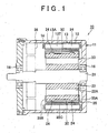
FIG. 1 is a lateral sectional view of a motor according to an embodiment of the invention; -
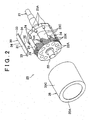
FIG. 2 is an exploded perspective view of a rotor; -
FIG. 3A is a side view of a rotor yoke; -
FIG. 3B is a front view of a rotor yoke; -
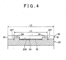
FIG. 4 is a lateral sectional view of a projection; -
FIG. 5 is a conceptual drawing of an electric power steering apparatus; -
FIG. 6A is a side view of a rotor yoke according to a variation; -
FIG. 6B is a front view of a rotor yoke according to a variation; -
FIG. 7 is an exploded perspective view of a rotor according to a variation; -
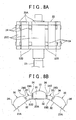
FIG. 8A is a side view of a rotor yoke according to a variation; -
FIG. 8B is a front view of a rotor yoke according to a variation; and -
FIG. 9 is a magnetic flux distribution diagram of a motor of the related art. - [First Embodiment] The following provides an explanation of a first embodiment of the invention based on
FIGS. 1 to 4 . Amotor 10 shown inFIG. 1 is a brushless, three-phase alternating current motor, and a stator 11 of thismotor 10 employs a structure in which astator core 13 is fixed to the inside of amotor housing 12 by engaging therewith. Themotor housing 12 has the form of, for example, a cylinder that is closed on both ends. In addition, thestator core 13 has a structure in which a plurality ofteeth 13T are protruding radially inward from the inner peripheral surface of a cylindrical body 13A, andelectromagnetic coils 14 are respectively wound around each of theseteeth 13T. - A
rotor 20 of thismotor 10 has a structure in which arotor shaft 21 passes through the center of arotor yoke 22, and a plurality ofsegment magnets 30 are fixed to the lateral surface of therotor yoke 22. As shown inFIG. 2 , thesegment magnets 30 are roughly in the form of long plates extending in the axial direction of therotor yoke 22, and are provided with a fixingflat surface 32 on the lateral surface on the side of therotor yoke 22, and a firstcurved surface 31 on the side opposite from the fixingflat surface 32. The firstcurved surface 31 has the form of a circular arc that gradually protrudes from both ends in the axial direction of thesegment magnet 30 towards the center in the width direction. In addition, both side surfaces 34 in the axial direction and both ends 33 in the width direction of thesegment magnets 30 are at right angles to the fixingflat surface 32. - The
rotor yoke 22 is composed by laminating a plurality ofsteel sheets 22K. For example, the plurality ofsteel sheets 22K is silicon steel sheets. Therotor yoke 22 is in the shape of a polygonal column having an overall shape of a regular polygon such as a regular decagon. The flat surface of each side of the regular polygon is amagnet fixing section 23A according to the invention, and as shown inFIG. 2 , a fixingflat surface 32 of thesegment magnet 30 is fixed to eachmagnet fixing section 23A. - In this embodiment, the fixing
flat surfaces 32 of thesegment magnets 30 are fixed to themagnet fixing sections 23A by an adhesive. Among each of themagnet fixing sections 23A, anadhesive depression 23C, which is depressed to an extremely shallow depth, for example, about 0.5 mm relative to both ends of therotor yoke 22 is formed in the central portion of therotor yoke 22 in the axial direction. When the segment magnets. 30 are fixed to themagnet fixing sections 23A by an adhesive, an adhesive layer of a prescribed thickness is formed between theadhesive depressions 23C and the fixingflat surfaces 32 as shown inFIG. 4 . Furthermore, as shown inFIG. 2 , the weight of therotor yoke 22 is reduced as a result of a plurality ofholes 22A being formed in therotor yoke 22 around the penetrating portion of therotor shaft 21.Projections 24 according to the invention are formed protruding from those portions sandwiched between adjacentadhesive depressions 23C among each of the corners of the polygon in therotor yoke 22. - As shown in
FIG.3A , theprojections 24 are provided at locations each at the same distance away from the center in the axial direction of therotor yoke 22 on both ends thereof, and in this embodiment, eachprojection 24 is arranged a location closer to both ends than the center of therotor yoke 22 in the axial direction. Furthermore, theprojections 24 provided in pairs in the axial direction of therotor yoke 22 may also be arranged at locations closer to the center than both ends of therotor yoke 22 in the axial direction, for example, locations that divide therotor yoke 22 into three equal portions in the axial direction, or may be arranged exactly in the middle between both ends and the center in the axial direction. - As shown
FIG 2 , Eachprojection 24 is composed by laminating protrudingpieces 24K protruding from a portion of the group ofsteel sheets 22K laminated between both ends and the center of therotor yoke 22 among the plurality ofsteel sheets 22K composing therotor yoke 22. Furthermore, each of thelaminated steel sheets 22K is positioned so as not to mutually shift out of position by interlocking sections, for example, not shown. - An enlarged view of the
projections 24 is shown inFIG. 3B . As shown inFIG 3B , bothside surfaces 24S of theprojections 24 rise from the mutually adjacentmagnet fixing sections 23A at roughly a right angle. As a result, together with both side surfaces 34 of thesegment magnets 30 being in parallel with the side surfaces 24S of theprojections 24, theprojections 24 have a structure in which the width thereof gradually widens the farther away from themagnet fixing sections 23A. In addition, a prescribed clearance is provided between both side surfaces 34 of thesegment magnets 30 and bothside surfaces 24S of theprojections 24. - Furthermore, among the
projections 24, the outer surfaces thereof facing to the outside of therotor 20 in the radial direction have a second curved surface concentric with the center of therotor 20, and the radius of the circle that includes that outer surface is smaller than the distance between the portion of the first curved surface 31' of thesegment magnets 30 closest to the center of therotor 20 such as both ends in the width direction of the firstcurved surface 31 and the center of therotor 20. - The length of the
projections 24 in the axial direction of therotor yoke 22 it set to be the minimum required length for ensuring strength capable of preventing deformation by external stress and preventing concentration of stress in thesegment magnets 30, and more specifically, the laminated thickness of six to eightsteel sheets 22K, for example. Furthermore, among all of thesteel sheets 22K composing therotor yoke 22, the number ofsteel sheets 22K having theprojections 24K is less than the number ofsteel sheets 22K not having theprojections 24K. - Here, as shown in
FIG 4 , a distance L1 between mutuallyseparated end surfaces 24T of theprojections 24 provided in pairs in the axial direction of therotor yoke 22 is shorter than an overall length L2 of thesegment magnets 30. Eachprojection 24 is arranged such that the bothend surfaces 24T are located closer to the center of therotor yoke 22 in the axial direction than both ends 33 of thesegment magnets 30. - A
cylindrical cover 35 is engaged with the outside of therotor yoke 22 and covers thesegment magnets 30. As shown inFIG. 1 , thecylindrical cover 35 has a structure in which thin-walledcylindrical portion 35C makes inside contact with thesegment magnets 30, andflanges cylindrical portion 35C. Theflanges rotor yoke 22. - As shown in
FIG 1 , therotor 20 is arranged so that the entirety of eachsegment magnet 30 in the lengthwise direction faces the inside of thestator core 13. Both ends of therotor shaft 21 are rotatably pivotally supported bybearings 16 incorporated in both end walls of themotor housing 12. - Furthermore, a
rotational position sensor 38 for detecting a rotational position of therotor 20 is incorporated within themotor 10 of this embodiment. - The configuration of the
motor 10 of this embodiment is as described above. Next, an explanation is provided of a method for producing the above-mentionedrotor 20. In producing therotor 20, a laminate consisting of a plurality ofsteel sheets 22K not having protrudingpieces 24K and a laminate consisting of a plurality ofsteel sheets 22K having protrudingpieces 24K are joined to produce therotor yoke 22, and therotor shaft 21 is then passed through therotor yoke 22. - Next, an adhesive is applied to the
adhesive depressions 23C in themagnet fixing sections 23A of therotor yoke 22. The fixingflat surface 32 of eachsegment magnet 30 is then adhered to eachmagnet fixing section 23A of therotor yoke 22. More specifically, the fixingflat surfaces 32 of thesegment magnets 30 are pressed against themagnet fixing sections 23A at locations where both ends 33 of thesegment magnets 30 are aligned with both ends of therotor yoke 22. Whereupon, together with the adhesive spreading over the entireadhesive depressions 23C, a portion thereof is pushed out in the width direction of thesegment magnets 30, and enters the clearance between both side surfaces 34 of thesegment magnets 30 and theprojections 24. As a result, together with the fixingflat surfaces 32 of thesegment magnets 30 being adhered to themagnet fixing sections 23A, both side surfaces 34 in the width direction of thesegment magnets 30 are adhered to theprojections 24 sandwiched by thesegment magnets 30 in the width direction. In addition, since adhesive is filled into the clearance, play of thesegment magnets 30 can be prevented. - Next, the
cylindrical cover 35 shown inFIG. 2 is engaged with therotor yoke 22. Here, thecylindrical cover 35 has one of theflanges 35B, for example, of the pair offlanges cylindrical portion 35C, and theflange 35B is welded or brazed, for example, to thecylindrical portion 35C after having engaged thecylindrical portion 35C with the outside of therotor yoke 22, thereby completing therotor 20. - Next, an explanation is provided of the interaction and effects of the
rotor 20 and themotor 10 of this embodiment. When a motor drive current in the form of a three-phase alternating current is applied to themotor 10, the intensity and direction of the magnetic flux of the plurality ofelectromagnetic coils 14 provided in the stator 11 change, and therotor 20 rotates relative to the stator 11 due to magnetic force between each of theelectromagnetic coils 14 and thesegment magnets 30. Here, theelectromagnetic coils 14 generate heat as a result of the application of current. The temperature of therotor 20 rises due to this heat. Whereupon, due to a difference in the coefficients of thermal expansion between therotor yoke 22 and thesegment magnets 30, adhesive between therotor yoke 22 and thesegment magnets 30 is subjected to stress. At this time, since the adhesive functions as a cushioning material to absorb thermal deformation of thesegment magnets 30 and therotor yoke 22, stress acting on thesegment magnets 30 can be alleviated. - However, if the
motor 10 is frequently used at a high load and the number of opportunities for reaching a high temperature increases, cracks may form in the adhesive as a result of being subjected to stress and the adhesive strength thereof may decrease. However, according to the configuration of therotor 20 of this embodiment, as shown inFIG. 3B , eachsegment magnet 30 is sandwiched in the width direction by a plurality of theprojections 24 provided on therotor yoke 22. Thus, even if adhesive strength between thesegment magnets 30 and therotor yoke 22 decreases due to the adhesive, the situation in which asegment magnet 30 is adsorbed to anadjacent segment magnet 30 within thecylindrical cover 35 is avoided. In addition, detachment of thesegment magnets 30 to the outside in the radial direction of therotor 20 is prevented by thecylindrical cover 35, and thesegment magnets 30 are restricted from moving in the axial direction of therotor 20 by theflanges cylindrical cover 35. - Moreover, in the
rotor 20 of this embodiment, since theprojections 24 are partially provided only at two locations in the axial direction of therotor yoke 22, in comparison with projections being formed continuously between both ends in the axial direction of therotor yoke 22, leakage of magnetism from thesegment magnets 30 to theprojections 24 can be inhibited. As a result, together with reductions in output torque of themotor 10 caused by magnetic leakage being minimized, torque ripple and cogging torque are also minimized, thereby making it possible to improve motor characteristics. Furthermore, the motor can be made smaller and lightweight as a result of minimizing decreases in output torque of themotor 10. - Moreover, in the
rotor 20 of this embodiment, sinceprojections 24 provided in pairs in the axial direction of therotor yoke 22 are respectively arranged so as to be located closer to the central portion of therotor yoke 22 in the axial direction than both ends 33 in the axial direction of thesegment magnets 30, the length of theprojections 24 in the axial direction of therotor yoke 22 is only required to be the minimum required length for ensuring strength of theprojections 24 and preventing concentration of stress in thesegment magnets 30, thereby eliminating the need for the length of theprojections 24 to be excessively long in consideration of shifting of thesegment magnets 30 attributable to tolerance. Accordingly, magnetic leakage can be inhibited more effectively. - Moreover, in the case of arranging the
projections 24 on both ends of therotor yoke 22, if therotor 20 shifts even slightly in the axial direction from the proper location thereof with respect to the stator 11, since a portion of theprojections 24 protrude outside the stator 11, dispersion of motor characteristics become comparatively large even if that shift is within the allowed assembly range. In contrast, in therotor 20 of this embodiment, since theprojections 24 do not protrude outside the stator 11 in the case of a shift by therotor 20 to the extent that is still within the allowed assembly range, dispersion of motor characteristics can be held to a comparatively low level. - [Second Embodiment] The following provides an explanation of an embodiment of an electric power steering apparatus according to the invention. As shown in
FIG. 5 , an electricpower steering apparatus 100 of this embodiment is provided with a turningwheel connecting shaft 102 extending between a pair of turningwheels 101 provided on avehicle 110, and ashaft case 103 covering the outside of the turningwheel connecting shaft 102. Both ends of the turningwheel connecting shaft 102 are connected to eachturning wheel 101 viatie rods 102T, and theshaft case 103 is fixed to the chassis of thevehicle 110. In addition, a rack (not shown) is formed at an intermediate portion of the turningwheel connecting shaft 102, and a pinion (not shown) massing through the intermediate portion of theshaft case 103 from the side meshes with this rack. - A steering
shaft 106 is connected to the upper end of the pinion, and asteering wheel 107 is further connected to the upper end of thesteering shaft 106. Therotor 20 of themotor 10 explained in the first embodiment is connected to an intermediate portion of thesteering shaft 106 via areduction gear groove 108. In addition, asteering angle sensor 111 and atorque sensor 112 are attached to thesteering shaft 106, which together with detecting the steering angle θs of thesteering wheel 107, detect the steering torque Tf applied to thesteering shaft 106. Moreover, avelocity sensor 113 for detecting velocity V accompanying rotation of the turningwheels 101 is provided in the vicinity of the turningwheels 101. Asteering control apparatus 114 drives themotor 10 corresponding to operating status based on the detection signals of thesteering angle sensor 111, thetorque sensor 112 and thevelocity sensor 113, thereby enabling the turningwheels motor 10 assists operation of the steering wheel by a driver. - In this manner, the electric
power steering apparatus 100 of this embodiment is provided with themotor 10 explained in the first embodiment as a drive source, and since themotor 10 has improved motor characteristics, the steering feel of the electricpower steering apparatus 100 is stable. - [Other Embodiments] The invention is not limited to the previously described embodiments, but rather embodiments in the manner of those explained to follow are also included within the scope of the invention. Moreover, in addition to the embodiments explained below, the invention can also be carried out by modifying in various ways within a range that does not deviate from the gist thereof.
- (1) Although the
segment magnets 30 are fixed to therotor yoke 22 by an adhesive in the above-mentioned first embodiment, a structure may also be employed in which thesegment magnets 30 are fixed to therotor yoke 22 with theprojections 24 and thecylindrical cover 35 only without using an adhesive. More specifically, a configuration is employed in which thesegment magnets 30 are clamped from the direction of width betweenadjacent projections 24 sandwiched by themagnet fixing sections 23A. - (2) In addition, the
segment magnets 30 may be fixed to therotor yoke 22 with theprojections 24 only without using an adhesive or thecylindrical cover 35. More specifically, in addition to making the cross-sectional shapes of both side surfaces 34 of thesegment magnets 30 roughly trapezoidal by inclining towards the fixingflat surfaces 32 so as to move away from each other as they approach the fixingflat surfaces 32, the side surfaces 24S of theadjacent projections 24 on both sides of themagnet fixing sections 23A are inclined so as to move away from each other as they approach themagnet fixing sections 23A, thereby resulting in a configuration in which theseside surfaces 24S and the side surfaces 32 of thesegment magnets 30 make contact with each other. In addition, thesegment magnets 30 are prevented from moving in the axial direction of therotor 20 by frictionally locking the side surfaces 24S of theprojections 24 with the side surfaces 34 of thesegment magnets 30. - (3) Although the
projections 24 are composed in the first embodiment by integrally forming protrudingpieces 24K on thesteel sheets 22K composing therotor yoke 22 and laminating a plurality of the protrudingpieces 24K, theprojections 24 may be composed with components separate from therotor yoke 22, and a configuration may be employed, for example, in which theprojections 24 are fastened by screws to the boundary portions of adjacentmagnet fixing sections 23A. - (4) In addition, although the
rotor yoke 22 was composed by laminating thesteel sheets 22K, it may also be composed with a mass of a magnetic material such as a compressed powder magnetic core compression molded with a die after mixing a magnetic metal powder and a resin powder. - (5) As shown in
FIGS. 6A and 6B , ashallow groove 23M extending between both ends in the axial direction of therotor yoke 22 and depressed relative to theadhesive depression 23C is formed in eachmagnet fixing section 23A, and an adhesive may be received in theshallow groove 23M and theadhesive depression 23C. As a result, an adhesive layer of a prescribed thickness is also formed between both ends of thesegment magnets 30 and themagnet fixing sections 23A, thereby enabling thesegment magnets 30 and themagnet fixing sections 23A to be reliably adhered. - (6) The
rotor yoke 22 may also be configured in the following manner. Namely, as shown inFIG. 7 , aflat surface 23B is formed at each corner of the polygon in therotor yoke 22. As shown inFIG.S 8A and 8B , eachprojection 24 stands upright from thisflat surface 23B, and bothside surfaces 24S thereof are rising at roughly a right angle from themagnet fixing sections 23A located adjacent to theflat surface 23B on both sides. Here, although a configuration may be employed in which the portion of theflat surface 23B sandwiched between adjacentadhesive depressions 23C is depressed to an extremely shallow depth by the same amount as the depth of theadhesive depressions 23C relative to the portion not sandwiched between adjacentadhesive depressions 23C, this portion may also not be depressed. In the case of employing a configuration in which this portion is not depressed, since the portions where theflat surface 23B is formed protrude relative to theadhesive depressions 23C, all four sides of theadhesive depressions 23C are surrounded by a level difference, thereby making it possible to retain the adhesive within theadhesive depressions 23C. - (7) Although a configuration is employed in the above-mentioned first embodiments in which the
projections 24 are arranged at locations sandwiched between adjacentadhesive depressions 23C in the central portion in the axial direction of therotor yoke 22, a configuration may also be employed in which theprojections 24 are arranged at locations not sandwiched between theadhesive depressions 23C (at both ends of therotor yoke 22 in the axial direction). - (8) Although the invention is applied to a so-called column electric power steering apparatus, in which a
motor 10 is coupled with a gear to an intermediate location of thesteering shaft 106, in the above-mentioned second embodiments, the invention may also be applied to a so-called rack electric power steering apparatus in which the entire motor has a hollow structure, a ball nut is fixed therein, and the ball nut meshes with ball threads formed at an intermediate portion of the turningwheel connecting shaft 102, or the invention may be applied to a pinion electric power steering apparatus, in which a motor is coupled to a turning wheel connecting shaft with a rack and pinion mechanism. Moreover, the invention is not only applied to an electric power steering apparatus, but may also be applied to an industrial robot. - (9) Although the invention is applied to the
rotor 20 of themotor 10 used as a drive source of an electricpower steering apparatus 100 in the second embodiment, the invention may also be applied to a rotor of an industrial motor. - (10) Although the
projections 24 are provided at locations shifted towards the center in the axial direction of therotor yoke 22 from both ends 33' in the axial direction of thesegment magnets 30 in the second embodiment, theprojections 24 may also be provided so as to lie in the same plane as both ends in the axial direction of therotor yoke 22. Since projections (24) are partially provided at only two locations in the axial direction of a rotor yoke (22) in a rotor (20), leakage of magnetism from segment magnets (30) to the projections (24) is inhibited as compared with the projections (24) being formed continuously over the entire axial direction. As a result, reduction of output torque of a motor (10) caused by magnetic leakage is minimized while also minimizing torque ripple and cogging torque, thereby making it possible to improve motor characteristics. In addition, steering feel is stable in an electric power steering apparatus (100) provided with this motor (10) as a drive source.
Claims (8)
- A motor rotor comprising:a rotor yoke (22);a plurality of magnet fixing sections (23A) formed on a lateral surface of the rotor yoke (22);segment magnets (30) respectively fixed to the magnet fixing sections (23A) andextending in the axial direction of the rotor yoke (22); andprojections (24) provided at each boundary section located between each of the adjacent magnet fixing sections (23A) of the rotor yoke (22) and protruding outward from the rotor yoke (22), characterized in thatthe projections (24) are provided in pairs in the axial direction of the rotor yoke (22).
- The motor rotor according to claim 1, wherein the projections (24) provided in pairs in the axial direction of the rotor yoke (22) are arranged at locations between each ends of the rotor yoke (22) and the center of the rotor yoke (22) in the axial direction.
- The motor rotor according to claim 1 or 2, further comprising:an adhesive depression (23C), which is formed by depressing the intermediate portion of the rotor yoke (22) in the axial direction relative to both ends of the rotor yoke (22), and which is formed in each of the magnet fixing sections (23A);wherein the projections (24) are arranged at locations sandwiched by the adhesive depressions (23C) of the adjacent magnet fixing sections (23A).
- The motor rotor according to claim 3, further comprising:a groove (23M) that is provided in the adhesive depression (23C).
- The motor rotor according to any one of claims 1 to 4, further comprising:a cylindrical cover (35) that engages with the outside of the rotor yoke (22) and covers the plurality of segment magnets (30).
- The motor rotor according to claim 5, wherein the cylindrical cover (35) includes a cylindrical portion (35C), and a flange (35A, 35B) extending radially inward from an end in the axial direction of the cylindrical portion (35C).
- The motor rotor according to any one of claims 1 to 6, wherein the rotor yoke (22) is in the shape of a polygonal column.
- The motor rotor according to any one of claim 1 to 7, wherein the rotor (20) is used in a motor (10) of an electric power assisting steering apparatus for assisting steering effort from the steering wheel (107).
Applications Claiming Priority (2)
| Application Number | Priority Date | Filing Date | Title |
|---|---|---|---|
| JP2008109828A JP5454753B2 (en) | 2008-04-21 | 2008-04-21 | Motor rotor and electric power steering device |
| JP2008115137A JP5501572B2 (en) | 2008-04-25 | 2008-04-25 | Motor rotor and electric power steering device |
Publications (3)
| Publication Number | Publication Date |
|---|---|
| EP2112743A2 true EP2112743A2 (en) | 2009-10-28 |
| EP2112743A3 EP2112743A3 (en) | 2016-10-19 |
| EP2112743B1 EP2112743B1 (en) | 2019-07-03 |
Family
ID=40910956
Family Applications (1)
| Application Number | Title | Priority Date | Filing Date |
|---|---|---|---|
| EP09158260.1A Active EP2112743B1 (en) | 2008-04-21 | 2009-04-20 | Motor rotor and electric power steering apparatus |
Country Status (1)
| Country | Link |
|---|---|
| EP (1) | EP2112743B1 (en) |
Cited By (1)
| Publication number | Priority date | Publication date | Assignee | Title |
|---|---|---|---|---|
| EP2888803B1 (en) * | 2012-08-22 | 2022-11-16 | BSH Hausgeräte GmbH | Home appliance with electric drive motor comrpising a permanent magnet rotor |
Citations (1)
| Publication number | Priority date | Publication date | Assignee | Title |
|---|---|---|---|---|
| JP2006271057A (en) | 2005-03-23 | 2006-10-05 | Toshiba Mitsubishi-Electric Industrial System Corp | Permanent magnet synchronous motor rotor |
Family Cites Families (4)
| Publication number | Priority date | Publication date | Assignee | Title |
|---|---|---|---|---|
| JPH11332145A (en) * | 1998-05-12 | 1999-11-30 | Japan Servo Co Ltd | Rotor of motor having magnet |
| JP3779097B2 (en) * | 1999-07-23 | 2006-05-24 | 日本電産サンキョー株式会社 | Electric motor rotor |
| JP2005065388A (en) * | 2003-08-08 | 2005-03-10 | Favess Co Ltd | Permanent magnet rotating electric machine |
| CN1985424B (en) * | 2004-07-16 | 2010-07-07 | 株式会社美姿把 | Magnet fixing structure of rotating electric machine |
-
2009
- 2009-04-20 EP EP09158260.1A patent/EP2112743B1/en active Active
Patent Citations (1)
| Publication number | Priority date | Publication date | Assignee | Title |
|---|---|---|---|---|
| JP2006271057A (en) | 2005-03-23 | 2006-10-05 | Toshiba Mitsubishi-Electric Industrial System Corp | Permanent magnet synchronous motor rotor |
Cited By (1)
| Publication number | Priority date | Publication date | Assignee | Title |
|---|---|---|---|---|
| EP2888803B1 (en) * | 2012-08-22 | 2022-11-16 | BSH Hausgeräte GmbH | Home appliance with electric drive motor comrpising a permanent magnet rotor |
Also Published As
| Publication number | Publication date |
|---|---|
| EP2112743B1 (en) | 2019-07-03 |
| EP2112743A3 (en) | 2016-10-19 |
Similar Documents
| Publication | Publication Date | Title |
|---|---|---|
| US8040006B2 (en) | Motor rotor and electric power steering apparatus | |
| US20090261677A1 (en) | Motor rotor, electric power steering apparatus and production method thereof | |
| JP5108236B2 (en) | Rotor for motor | |
| EP1617540B1 (en) | Electric power steering apparatus | |
| JP6218997B1 (en) | Rotating electric machine, electric power steering device, and method of manufacturing rotating electric machine | |
| JP5359859B2 (en) | Brushless motor rotor, brushless motor, electric power steering apparatus, and method for manufacturing brushless motor rotor | |
| JPWO2008050637A1 (en) | Brushless motor | |
| WO2012137465A1 (en) | Rotor unit, rotating electrical machine, and method of manufacturing rotor unit | |
| JP2009044797A (en) | Electric motor | |
| JP2013162692A (en) | Brushless motor and electric power steering device | |
| JP2021535720A (en) | motor | |
| JP2011083056A (en) | Axial gap motor and electric power steering device | |
| WO2019064923A1 (en) | Rotor core, rotor, rotating electrical machine, and electric auxiliary system for automobiles | |
| JP5126487B2 (en) | IPM motor, manufacturing method thereof, and electric power steering apparatus | |
| EP2709241B1 (en) | Rear wheel steering apparatus for vehicle including rotor | |
| EP2112743B1 (en) | Motor rotor and electric power steering apparatus | |
| JP2006121821A (en) | Synchronous reluctance motor and electric steering device equipped with synchronous reluctance motor | |
| JP2012050271A (en) | Axial gap type motor | |
| JP2010076735A (en) | Electric assistant steering device | |
| JP2006242758A (en) | Resolver and vehicle steering system | |
| JP2005065388A (en) | Permanent magnet rotating electric machine | |
| JP5470913B2 (en) | Motor core, motor core unit using the same, brushless motor, electric power steering device using the same, and method for manufacturing motor core unit | |
| WO2017104436A1 (en) | Permanent magnet synchronization motor | |
| WO2022091198A1 (en) | Rotary electric machine and electric power steering device | |
| JP5966399B2 (en) | Brushless motor and electric power steering device |
Legal Events
| Date | Code | Title | Description |
|---|---|---|---|
| PUAI | Public reference made under article 153(3) epc to a published international application that has entered the european phase |
Free format text: ORIGINAL CODE: 0009012 |
|
| AK | Designated contracting states |
Kind code of ref document: A2 Designated state(s): AT BE BG CH CY CZ DE DK EE ES FI FR GB GR HR HU IE IS IT LI LT LU LV MC MK MT NL NO PL PT RO SE SI SK TR |
|
| REG | Reference to a national code |
Ref country code: DE Ref legal event code: R079 Ref document number: 602009058964 Country of ref document: DE Free format text: PREVIOUS MAIN CLASS: H02K0001270000 Ipc: H02K0015030000 |
|
| PUAL | Search report despatched |
Free format text: ORIGINAL CODE: 0009013 |
|
| AK | Designated contracting states |
Kind code of ref document: A3 Designated state(s): AT BE BG CH CY CZ DE DK EE ES FI FR GB GR HR HU IE IS IT LI LT LU LV MC MK MT NL NO PL PT RO SE SI SK TR |
|
| RIC1 | Information provided on ipc code assigned before grant |
Ipc: H02K 1/27 20060101ALI20160915BHEP Ipc: H02K 15/03 20060101AFI20160915BHEP |
|
| STAA | Information on the status of an ep patent application or granted ep patent |
Free format text: STATUS: REQUEST FOR EXAMINATION WAS MADE |
|
| 17P | Request for examination filed |
Effective date: 20170406 |
|
| RBV | Designated contracting states (corrected) |
Designated state(s): AT BE BG CH CY CZ DE DK EE ES FI FR GB GR HR HU IE IS IT LI LT LU LV MC MK MT NL NO PL PT RO SE SI SK TR |
|
| STAA | Information on the status of an ep patent application or granted ep patent |
Free format text: STATUS: EXAMINATION IS IN PROGRESS |
|
| 17Q | First examination report despatched |
Effective date: 20170811 |
|
| GRAP | Despatch of communication of intention to grant a patent |
Free format text: ORIGINAL CODE: EPIDOSNIGR1 |
|
| STAA | Information on the status of an ep patent application or granted ep patent |
Free format text: STATUS: GRANT OF PATENT IS INTENDED |
|
| INTG | Intention to grant announced |
Effective date: 20190117 |
|
| GRAJ | Information related to disapproval of communication of intention to grant by the applicant or resumption of examination proceedings by the epo deleted |
Free format text: ORIGINAL CODE: EPIDOSDIGR1 |
|
| STAA | Information on the status of an ep patent application or granted ep patent |
Free format text: STATUS: EXAMINATION IS IN PROGRESS |
|
| GRAR | Information related to intention to grant a patent recorded |
Free format text: ORIGINAL CODE: EPIDOSNIGR71 |
|
| GRAS | Grant fee paid |
Free format text: ORIGINAL CODE: EPIDOSNIGR3 |
|
| STAA | Information on the status of an ep patent application or granted ep patent |
Free format text: STATUS: GRANT OF PATENT IS INTENDED |
|
| GRAA | (expected) grant |
Free format text: ORIGINAL CODE: 0009210 |
|
| STAA | Information on the status of an ep patent application or granted ep patent |
Free format text: STATUS: THE PATENT HAS BEEN GRANTED |
|
| INTC | Intention to grant announced (deleted) | ||
| INTG | Intention to grant announced |
Effective date: 20190523 |
|
| AK | Designated contracting states |
Kind code of ref document: B1 Designated state(s): AT BE BG CH CY CZ DE DK EE ES FI FR GB GR HR HU IE IS IT LI LT LU LV MC MK MT NL NO PL PT RO SE SI SK TR |
|
| REG | Reference to a national code |
Ref country code: GB Ref legal event code: FG4D |
|
| REG | Reference to a national code |
Ref country code: CH Ref legal event code: EP Ref country code: AT Ref legal event code: REF Ref document number: 1152180 Country of ref document: AT Kind code of ref document: T Effective date: 20190715 |
|
| REG | Reference to a national code |
Ref country code: IE Ref legal event code: FG4D |
|
| REG | Reference to a national code |
Ref country code: DE Ref legal event code: R096 Ref document number: 602009058964 Country of ref document: DE |
|
| REG | Reference to a national code |
Ref country code: NL Ref legal event code: MP Effective date: 20190703 |
|
| REG | Reference to a national code |
Ref country code: LT Ref legal event code: MG4D |
|
| REG | Reference to a national code |
Ref country code: AT Ref legal event code: MK05 Ref document number: 1152180 Country of ref document: AT Kind code of ref document: T Effective date: 20190703 |
|
| PG25 | Lapsed in a contracting state [announced via postgrant information from national office to epo] |
Ref country code: CZ Free format text: LAPSE BECAUSE OF FAILURE TO SUBMIT A TRANSLATION OF THE DESCRIPTION OR TO PAY THE FEE WITHIN THE PRESCRIBED TIME-LIMIT Effective date: 20190703 Ref country code: BG Free format text: LAPSE BECAUSE OF FAILURE TO SUBMIT A TRANSLATION OF THE DESCRIPTION OR TO PAY THE FEE WITHIN THE PRESCRIBED TIME-LIMIT Effective date: 20191003 Ref country code: AT Free format text: LAPSE BECAUSE OF FAILURE TO SUBMIT A TRANSLATION OF THE DESCRIPTION OR TO PAY THE FEE WITHIN THE PRESCRIBED TIME-LIMIT Effective date: 20190703 Ref country code: NO Free format text: LAPSE BECAUSE OF FAILURE TO SUBMIT A TRANSLATION OF THE DESCRIPTION OR TO PAY THE FEE WITHIN THE PRESCRIBED TIME-LIMIT Effective date: 20191003 Ref country code: LT Free format text: LAPSE BECAUSE OF FAILURE TO SUBMIT A TRANSLATION OF THE DESCRIPTION OR TO PAY THE FEE WITHIN THE PRESCRIBED TIME-LIMIT Effective date: 20190703 Ref country code: FI Free format text: LAPSE BECAUSE OF FAILURE TO SUBMIT A TRANSLATION OF THE DESCRIPTION OR TO PAY THE FEE WITHIN THE PRESCRIBED TIME-LIMIT Effective date: 20190703 Ref country code: PT Free format text: LAPSE BECAUSE OF FAILURE TO SUBMIT A TRANSLATION OF THE DESCRIPTION OR TO PAY THE FEE WITHIN THE PRESCRIBED TIME-LIMIT Effective date: 20191104 Ref country code: NL Free format text: LAPSE BECAUSE OF FAILURE TO SUBMIT A TRANSLATION OF THE DESCRIPTION OR TO PAY THE FEE WITHIN THE PRESCRIBED TIME-LIMIT Effective date: 20190703 Ref country code: SE Free format text: LAPSE BECAUSE OF FAILURE TO SUBMIT A TRANSLATION OF THE DESCRIPTION OR TO PAY THE FEE WITHIN THE PRESCRIBED TIME-LIMIT Effective date: 20190703 Ref country code: HR Free format text: LAPSE BECAUSE OF FAILURE TO SUBMIT A TRANSLATION OF THE DESCRIPTION OR TO PAY THE FEE WITHIN THE PRESCRIBED TIME-LIMIT Effective date: 20190703 |
|
| PG25 | Lapsed in a contracting state [announced via postgrant information from national office to epo] |
Ref country code: GR Free format text: LAPSE BECAUSE OF FAILURE TO SUBMIT A TRANSLATION OF THE DESCRIPTION OR TO PAY THE FEE WITHIN THE PRESCRIBED TIME-LIMIT Effective date: 20191004 Ref country code: LV Free format text: LAPSE BECAUSE OF FAILURE TO SUBMIT A TRANSLATION OF THE DESCRIPTION OR TO PAY THE FEE WITHIN THE PRESCRIBED TIME-LIMIT Effective date: 20190703 Ref country code: IS Free format text: LAPSE BECAUSE OF FAILURE TO SUBMIT A TRANSLATION OF THE DESCRIPTION OR TO PAY THE FEE WITHIN THE PRESCRIBED TIME-LIMIT Effective date: 20191103 Ref country code: ES Free format text: LAPSE BECAUSE OF FAILURE TO SUBMIT A TRANSLATION OF THE DESCRIPTION OR TO PAY THE FEE WITHIN THE PRESCRIBED TIME-LIMIT Effective date: 20190703 |
|
| PG25 | Lapsed in a contracting state [announced via postgrant information from national office to epo] |
Ref country code: TR Free format text: LAPSE BECAUSE OF FAILURE TO SUBMIT A TRANSLATION OF THE DESCRIPTION OR TO PAY THE FEE WITHIN THE PRESCRIBED TIME-LIMIT Effective date: 20190703 |
|
| PG25 | Lapsed in a contracting state [announced via postgrant information from national office to epo] |
Ref country code: IT Free format text: LAPSE BECAUSE OF FAILURE TO SUBMIT A TRANSLATION OF THE DESCRIPTION OR TO PAY THE FEE WITHIN THE PRESCRIBED TIME-LIMIT Effective date: 20190703 Ref country code: PL Free format text: LAPSE BECAUSE OF FAILURE TO SUBMIT A TRANSLATION OF THE DESCRIPTION OR TO PAY THE FEE WITHIN THE PRESCRIBED TIME-LIMIT Effective date: 20190703 Ref country code: EE Free format text: LAPSE BECAUSE OF FAILURE TO SUBMIT A TRANSLATION OF THE DESCRIPTION OR TO PAY THE FEE WITHIN THE PRESCRIBED TIME-LIMIT Effective date: 20190703 Ref country code: DK Free format text: LAPSE BECAUSE OF FAILURE TO SUBMIT A TRANSLATION OF THE DESCRIPTION OR TO PAY THE FEE WITHIN THE PRESCRIBED TIME-LIMIT Effective date: 20190703 Ref country code: RO Free format text: LAPSE BECAUSE OF FAILURE TO SUBMIT A TRANSLATION OF THE DESCRIPTION OR TO PAY THE FEE WITHIN THE PRESCRIBED TIME-LIMIT Effective date: 20190703 |
|
| PG25 | Lapsed in a contracting state [announced via postgrant information from national office to epo] |
Ref country code: IS Free format text: LAPSE BECAUSE OF FAILURE TO SUBMIT A TRANSLATION OF THE DESCRIPTION OR TO PAY THE FEE WITHIN THE PRESCRIBED TIME-LIMIT Effective date: 20200224 Ref country code: SK Free format text: LAPSE BECAUSE OF FAILURE TO SUBMIT A TRANSLATION OF THE DESCRIPTION OR TO PAY THE FEE WITHIN THE PRESCRIBED TIME-LIMIT Effective date: 20190703 |
|
| REG | Reference to a national code |
Ref country code: DE Ref legal event code: R097 Ref document number: 602009058964 Country of ref document: DE |
|
| PLBE | No opposition filed within time limit |
Free format text: ORIGINAL CODE: 0009261 |
|
| STAA | Information on the status of an ep patent application or granted ep patent |
Free format text: STATUS: NO OPPOSITION FILED WITHIN TIME LIMIT |
|
| PG2D | Information on lapse in contracting state deleted |
Ref country code: IS |
|
| 26N | No opposition filed |
Effective date: 20200603 |
|
| PG25 | Lapsed in a contracting state [announced via postgrant information from national office to epo] |
Ref country code: SI Free format text: LAPSE BECAUSE OF FAILURE TO SUBMIT A TRANSLATION OF THE DESCRIPTION OR TO PAY THE FEE WITHIN THE PRESCRIBED TIME-LIMIT Effective date: 20190703 |
|
| PG25 | Lapsed in a contracting state [announced via postgrant information from national office to epo] |
Ref country code: MC Free format text: LAPSE BECAUSE OF FAILURE TO SUBMIT A TRANSLATION OF THE DESCRIPTION OR TO PAY THE FEE WITHIN THE PRESCRIBED TIME-LIMIT Effective date: 20190703 |
|
| REG | Reference to a national code |
Ref country code: CH Ref legal event code: PL |
|
| PG25 | Lapsed in a contracting state [announced via postgrant information from national office to epo] |
Ref country code: LU Free format text: LAPSE BECAUSE OF NON-PAYMENT OF DUE FEES Effective date: 20200420 Ref country code: CH Free format text: LAPSE BECAUSE OF NON-PAYMENT OF DUE FEES Effective date: 20200430 Ref country code: LI Free format text: LAPSE BECAUSE OF NON-PAYMENT OF DUE FEES Effective date: 20200430 |
|
| REG | Reference to a national code |
Ref country code: BE Ref legal event code: MM Effective date: 20200430 |
|
| PG25 | Lapsed in a contracting state [announced via postgrant information from national office to epo] |
Ref country code: BE Free format text: LAPSE BECAUSE OF NON-PAYMENT OF DUE FEES Effective date: 20200430 |
|
| REG | Reference to a national code |
Ref country code: FR Ref legal event code: PLFP Year of fee payment: 13 |
|
| GBPC | Gb: european patent ceased through non-payment of renewal fee |
Effective date: 20200420 |
|
| PG25 | Lapsed in a contracting state [announced via postgrant information from national office to epo] |
Ref country code: GB Free format text: LAPSE BECAUSE OF NON-PAYMENT OF DUE FEES Effective date: 20200420 Ref country code: IE Free format text: LAPSE BECAUSE OF NON-PAYMENT OF DUE FEES Effective date: 20200420 |
|
| PGFP | Annual fee paid to national office [announced via postgrant information from national office to epo] |
Ref country code: FR Payment date: 20210309 Year of fee payment: 13 |
|
| PGFP | Annual fee paid to national office [announced via postgrant information from national office to epo] |
Ref country code: DE Payment date: 20210323 Year of fee payment: 13 |
|
| PG25 | Lapsed in a contracting state [announced via postgrant information from national office to epo] |
Ref country code: MT Free format text: LAPSE BECAUSE OF FAILURE TO SUBMIT A TRANSLATION OF THE DESCRIPTION OR TO PAY THE FEE WITHIN THE PRESCRIBED TIME-LIMIT Effective date: 20190703 Ref country code: CY Free format text: LAPSE BECAUSE OF FAILURE TO SUBMIT A TRANSLATION OF THE DESCRIPTION OR TO PAY THE FEE WITHIN THE PRESCRIBED TIME-LIMIT Effective date: 20190703 |
|
| PG25 | Lapsed in a contracting state [announced via postgrant information from national office to epo] |
Ref country code: MK Free format text: LAPSE BECAUSE OF FAILURE TO SUBMIT A TRANSLATION OF THE DESCRIPTION OR TO PAY THE FEE WITHIN THE PRESCRIBED TIME-LIMIT Effective date: 20190703 |
|
| REG | Reference to a national code |
Ref country code: DE Ref legal event code: R119 Ref document number: 602009058964 Country of ref document: DE |
|
| PG25 | Lapsed in a contracting state [announced via postgrant information from national office to epo] |
Ref country code: FR Free format text: LAPSE BECAUSE OF NON-PAYMENT OF DUE FEES Effective date: 20220430 Ref country code: DE Free format text: LAPSE BECAUSE OF NON-PAYMENT OF DUE FEES Effective date: 20221103 |