EP2112688A1 - Semiconductor package - Google Patents
Semiconductor package Download PDFInfo
- Publication number
- EP2112688A1 EP2112688A1 EP08711401A EP08711401A EP2112688A1 EP 2112688 A1 EP2112688 A1 EP 2112688A1 EP 08711401 A EP08711401 A EP 08711401A EP 08711401 A EP08711401 A EP 08711401A EP 2112688 A1 EP2112688 A1 EP 2112688A1
- Authority
- EP
- European Patent Office
- Prior art keywords
- base portion
- semiconductor device
- heat
- thin plates
- semiconductor
- Prior art date
- Legal status (The legal status is an assumption and is not a legal conclusion. Google has not performed a legal analysis and makes no representation as to the accuracy of the status listed.)
- Withdrawn
Links
Images


Classifications
-
- H—ELECTRICITY
- H10—SEMICONDUCTOR DEVICES; ELECTRIC SOLID-STATE DEVICES NOT OTHERWISE PROVIDED FOR
- H10W—GENERIC PACKAGES, INTERCONNECTIONS, CONNECTORS OR OTHER CONSTRUCTIONAL DETAILS OF DEVICES COVERED BY CLASS H10
- H10W40/00—Arrangements for thermal protection or thermal control
- H10W40/20—Arrangements for cooling
- H10W40/25—Arrangements for cooling characterised by their materials
-
- H—ELECTRICITY
- H10—SEMICONDUCTOR DEVICES; ELECTRIC SOLID-STATE DEVICES NOT OTHERWISE PROVIDED FOR
- H10W—GENERIC PACKAGES, INTERCONNECTIONS, CONNECTORS OR OTHER CONSTRUCTIONAL DETAILS OF DEVICES COVERED BY CLASS H10
- H10W40/00—Arrangements for thermal protection or thermal control
- H10W40/70—Fillings or auxiliary members in containers or in encapsulations for thermal protection or control
- H10W40/73—Fillings or auxiliary members in containers or in encapsulations for thermal protection or control for cooling by change of state
Definitions
- This invention relates to a semiconductor package which accommodates a semiconductor device therein.
- the semiconductor device is formed by mounting a desired circuit pattern on a surface of a substrate formed of substrate material typified by silicon, where a large amount of heat is generated from the circuit pattern during operation of the semiconductor device. When the temperature of the circuit pattern exceeds a certain temperature, the circuit pattern cannot play in a desired performance.
- At least the base portion of the package main body is configured by material with high heat conductivity, for example, copper, aluminum, copper alloy, or aluminum alloy, in order to radiate heat which is generated by the semiconductor device.
- Heat which is generated by the semiconductor device accommodated in the semiconductor device accommodating portion is transferred to the package main body, mainly to the base portion, and the heat is further radiated to an object with which the package main body, mainly the base portion, comes in contact, for example, a semiconductor package supporting body on which the base portion is placed and supported, air surrounding the package main body, or the like.
- Jpn. Pat. Appln. KOKAI Publication No. 2004-288949 discloses one example of the structure for improving heat transfer efficiency such as described above.
- a graphite sheet is in close contact with a second surface of a base portion of a package main body.
- the graphite sheet has high heat conductivity and it rapidly diffuses heat transferred from the second surface of the base portion of the package main body in a direction extending along the second surface, so that heat transfer efficiency from the base portion of the package main body to an object adjacent thereto is enhanced.
- Jpn. Pat. Appln. KOKAI Publication No. 2001-144237 discloses another example of the structure for improving heat transfer efficiency such as described above.
- this structure for improving heat transfer efficiency a plurality of graphite sheets and a plurality of sheet metals are alternately stacked on one another.
- the sheet metal increases a heat transfer amount due to its large heat capacity, while the graphite sheet improves heat radiation from the sheet metal owing to its large heat conductivity.
- the plurality of graphite sheets and the plurality of sheet metals alternately stacked to one another are mutually brought in close contact with one another and fixed to one another by screws, glue, or adhesive.
- the structure for improving heat transfer efficiency described in Jpn. Pat. Appln. KOKAI Publication No. 2001-144237 is improved in radiation efficiency as compared with the structure for improving heat transfer efficiency described in Jpn. Pat. Appln. KOKAI Publication No. 2004-288949 .
- the fixation by the screws, glue, or adhesive as described above however, such a fact that evenness of the degree of mutual close contact between the plurality of graphite sheets and the plurality of sheet metals is reduced easily remains. That is, mutual heat transfer efficiency between the plurality of graphite sheets and the plurality of sheet metals becomes uneven easily. Further, the heat transfer efficiency of the graphite sheet in the thickness direction is smaller than that in the direction along the surface of the graphite sheet.
- an object of this invention is to provide a semiconductor package including a structure for improving heat transfer efficiency, whose heat transfer efficiency is further excellent as compared with the various structures for improving heat transfer efficiency such as described above, whose thickness can be made thin, and whose manufacture is easy.
- a semiconductor package comprises: a package main body including a base portion having a first surface and a second surface on a side opposite to the first surface, and a semiconductor device accommodating portion provided on the first surface, in which a semiconductor device is accommodated; electric terminals provided in the semiconductor device accommodating portion, electrically connected to the semiconductor device, and exposed to an outer surface of the semiconductor device accommodating portion; and a high heat transfer element having a heat conductivity higher than that of the base portion, disposed in the base portion to extend from a heat generation site corresponding position corresponding to a heat generating site of the semiconductor device to a position in an outside of the heat generation site corresponding position, and transferring heat generated from the heat generating site of the semiconductor device from the heat generation site corresponding position to the outside position in the base portion.
- the semiconductor package is characterized in that the base portion is configured by bringing a plurality of thin plates in close contact with each other to bond the thin plates to each other integrally, and the high heat transfer element includes at least one combination of a flow passage extending from the heat generation site corresponding position to the outside position in the base portion and heat transfer fluid sealed in the flow passage to transfer heat by phase-change thereof.
- a semiconductor package comprises: a package main body including a base portion having a first surface and a second surface on a side opposite to the first surface, and a semiconductor device accommodating portion provided on the first surface, in which a semiconductor device is accommodated; electric terminals provided in the semiconductor device accommodating portion, electrically connected to the semiconductor device, and exposed to an outer surface of the semiconductor device accommodating portion; and a high heat transfer element having a heat conductivity higher than that of the base portion, disposed in the base portion to extend from a heat generation site corresponding position corresponding to a heat generating site of the semiconductor device to a position in an outside of the heat generation site corresponding position, and transferring heat generated from the heat generating site of the semiconductor device from the heat generation site corresponding position to the outside position in the base portion.
- the semiconductor package is characterized in that the base portion is configured by bringing a plurality of thin plates in close contact with each other to bond the thin plates to each other integrally, and the high heat transfer element includes at least one heat pipe configured independently of the base portion and arranged in the base portion so as to extend from the heat generation site corresponding position to the outside position.
- heat generated by the heat generating site of the semiconductor device accommodated in the semiconductor device accommodating portion of the package main body is transferred in the base portion from the heat generating site corresponding portion to the position in the outside of the heat generating site corresponding portion rapidly by the high heat transfer element provided in the base portion of the package main body, having heat conductivity higher than that of the base portion, and disposed in the base portion so as to extend from the heat generating site corresponding position corresponding to the heat generating site of the semiconductor device to the position in the outside of the heat generating site corresponding position, the high heat transfer element including at least one combination of the flow passage extending in the base portion from the heat generating site corresponding position to the position in the outside of the heat generating site corresponding position and the heat transfer fluid sealed in the flow passage and transferring heat by the phase change, or the heat high-transfer element including at least one heat pipe configured independently of the base portion and disposed in the base portion so as to extend from the heat generating site corresponding position
- the heat is rapidly diffused in the base portion from the heat generating site corresponding position to the position in the outside of the heat generating site corresponding position, and further it is radiated rapidly to an object contacting with the package main body, for example, a semiconductor package supporting body on which the package main body is placed and supported, air surrounding the package main body, or the like.
- the package main body for example, a semiconductor package supporting body on which the package main body is placed and supported, air surrounding the package main body, or the like.
- the base portion of the package main body is configured by brining the plurality of thin plates in close contact with one another and bonding them to one another integrally and the high heat transfer element is provided in the base portion, the evenness of the degree of close contact of the high heat transfer element to the base portion is enhanced so that the mutual heat transfer efficiency between the base portion and the high heat transfer element is increased. Further, the thickness of the base portion of the package main body can be made thin and a manufacture thereof is made easy.
- a configuration of a semiconductor package SP1 according to a first embodiment of the present invention will be explained with reference to FIG. 1 and FIG. 2 .
- the semiconductor package SP1 is provided with a package main body 20 including a base portion 10 having a first surface 10a and a second surface 10b positioned on a side opposite to the first surface 10a and configured by bringing a plurality of thin plates 12, 14 in close contact with each other and bonding (for example, diffusion bonding) them integrally, and a semiconductor device accommodating portion 18 which is provided on the first surface 10a and in which semiconductor devices 16 are accommodated.
- a package main body 20 including a base portion 10 having a first surface 10a and a second surface 10b positioned on a side opposite to the first surface 10a and configured by bringing a plurality of thin plates 12, 14 in close contact with each other and bonding (for example, diffusion bonding) them integrally, and a semiconductor device accommodating portion 18 which is provided on the first surface 10a and in which semiconductor devices 16 are accommodated.
- the semiconductor device accommodating portion 18 is provided with electric terminals 22 electrically connected to the semiconductor devices 16 accommodated in the semiconductor device accommodating portion 18, and exposed to an outer surface of the semiconductor device accommodating portion 18.
- peripheral circuit mounting boards 23 each provided with a peripheral circuit for the semiconductor device 16 are also accommodated in the semiconductor device accommodating portion 18, and the semiconductor devices 16 are connected to the electric terminals 22 via wires on the peripheral circuit mounting boards 23.
- the plurality of thin plates 12, 14 are made of metal material having high heat conductivity (for example, it may includes copper, aluminum, copper alloy, aluminum alloy, or metal material having heat conductivity approximately equal to those of the materials, the heat conductivity of copper being about 400W/mK).
- metal material having high heat conductivity for example, it may includes copper, aluminum, copper alloy, aluminum alloy, or metal material having heat conductivity approximately equal to those of the materials, the heat conductivity of copper being about 400W/mK.
- FIG. 1 only two thin plates 12, 14 are shown, but the number of thin plates brought in close contact with one another mutually to be integrally bonded to configure the base portion 10 may be more than two in accordance with the aspect of the present invention.
- the semiconductor device accommodating portion 18 has a cylindrical shape providing an internal space accommodating the semiconductor devices 16 and peripheral circuit mounting boards 23 provided with peripheral circuits relating to the semiconductor devices 16, and surrounding a predetermined region of the first surface 10a of the base portion 10.
- the semiconductor devices 16 and the peripheral circuit mounting boards 23 are placed on the predetermined region of the first surface 10a.
- the semiconductor device accommodating portion 18 includes a lid 24 covering an opening opposite to the predetermined region of the first surface 10a of the base portion 10.
- the lid 24 covers the opening after the semiconductor devices 16 and the peripheral circuit mounting boards 23 are placed on the predetermined region of the first surface 10a and mutual connections among the semiconductor devices 16, the peripheral circuit mounting boards 23, and the electric terminals 22 are finished, so that the internal space is sealed from the outside space.
- a high heat transfer element 26 having heat conductivity higher than that of the base portion 10 is provided in the base portion 10, the high heat transfer element 26 being arranged in the base portion 10 from a heat generating site corresponding position corresponding to heat generating sites of the semiconductor devices 16 accommodated in the semiconductor device accommodating portion 18 (a region adjacent to the heat generating sites of the semiconductor devices 16 on the first surface 10a of the base portion 10) to a position in the outside of the heat generating site corresponding position, in the outside of the semiconductor device accommodating portion 18 in this embodiment.
- the high heat transfer element 26 transfers heat generated by the heat generating sites of the semiconductor devices 16 to the outside position from the heat generation site corresponding position in the base portion 20.
- the high heat transfer element 26 includes at least one combination of a flow passage 28 extending from the heat generating site corresponding position up to the outside position in the base portion 20 and heat transfer fluid sealed in the flow passage 28 and transferring heat by its phase change.
- the heat transfer fluid absorbs heat from the semiconductor devices 16 at the heat generation site corresponding position in the base portion 20 and changes its phase from liquid to gas, and then flows up to the outside position in the flow passages 28 by its convection.
- the heat transfer fluid gasified and flown by convection radiates heat at the outside position which is far from the heat generating site corresponding position and whose temperature is lower than that of the heat generating site corresponding position, and changes its phase to liquid, and then flows to the heat generating site corresponding position in the flow passage 28.
- various kinds of ones have been widely known.
- the thin plates 12, 14 of the base portion 10 have openings each of which has a shape corresponding to the flow passage 28, and they are brought in close contact with each other and bonded to each other integrally in a state that the at least parts of openings are overlapped with each other.
- the flow passages 28 configured in the base portion 10 in this manner can be easily provided in the base portion 10 with various numbers and various arrangements. That is, it is possible to transfer heat from the heat generating site corresponding position to a desired outside position in the base portion 10 effectively.
- the peripheral circuit mounting boards 23, or the both thereof due to differences in the coefficients of the thermal expansions between the substrate (generally, made of silicon) of the semiconductor device 16 or the peripheral circuit mounting board 23 (generally, made of ceramic) and the base portion 10 becomes large.
- at least one thin sheet 30 having a coefficient of thermal expansion equal to or less than the coefficient of thermal expansion of the substrate of the semiconductor device 16 or the peripheral circuit mounting board 23 can be included in the plurality of thin plates configuring the base portion 10.
- a material for the thin plate 30, for example, molybdenum is known.
- the thickness or the shape of such a thin plate 30 or arrangement of the thin plate 30 in the base portion 10 is set such that an occurrence of crack or break in the substrate of the semiconductor device 16, the peripheral circuit mounting board 23, or the both thereof due to the difference in the coefficients of thermal expansions can be prevented and a desired heat transfer function of the base portion 10 is not reduced.
- the modification is different from the first embodiment in that a ratio of each area of a first surface 10'a and a second surface 10'b of a base portion 10' to that of the semiconductor device accommodating portion 18 is largely expanded as compared with a ratio of each area of the first surface 10a and the second surface 10b of the base portion 10 to the semiconductor device accommodating portion 18 in the package main body 20 according to the first embodiment, in order to increase a radiation function of the base portion 10' of the package main body 20.
- the number of combinations of flow passages 28' and heat transfer fluids sealed in the flow passages 28' in the high heat transfer element 26 of the base portion 10' and/or the arrangement density of the combinations and/or an extending length of each combination is increased in response to the expansion of each area of the first surface 10'a and the second surface 10'b of the base portion 10'.
- the peripheral circuit mounting board 23, or the both thereof in order to prevent the substrate of the semiconductor device 16, the peripheral circuit mounting board 23, or the both thereof from being cracked or broken by the differences in the coefficients of the thermal expansions between the substrate (generally, made of silicon) of the semiconductor device 16 or the peripheral circuit mounting board 23 (generally, made of ceramic) and the base portion 10, at least one thin sheet 30 having a coefficient of thermal expansion equal to or less than the coefficient of thermal expansion of the substrate of the semiconductor device 16 or the peripheral circuit mounting board 23 can be included in the plurality of thin plates configuring the base portion 10'.
- the semiconductor package SP1' according to the modification of FIG. 3 can be combined with a conventional radiation performance enhancing mechanism 32 as shown in FIG. 4 .
- the radiation performance enhancing mechanism 32 shown in FIG. 4 includes a semiconductor package supporting body 32a, on which the second surface 10'b of the base portion 10' of the package main body 20 of the semiconductor package SP1' is placed in a close contacting state with the semiconductor supporting body 32a, and a cooling fan 32b blowing air toward the semiconductor package supporting body 32a, and the base portion 10' of the package main body 20 of the semiconductor package SP1' is fixed to the semiconductor package supporting body 32a by known fixing means, for example, fixing screws, preferably fixing screws made of metal having high heat conductivity (for example, copper, aluminum, copper alloy, aluminum alloy, or metal material having heat conductivity approximately equal to those of these materials), or soldering.
- fixing screws for example, fixing screws, preferably fixing screws made of metal having high heat conductivity (for example, copper, aluminum, copper alloy, aluminum alloy, or metal material having heat conductivity approximately equal to those of these materials), or soldering.
- each area of the first surface 10'a and the second surface 10'b of the base portion 10' is expanded.
- wires (not shown)
- cutouts 34 can be formed in a plurality of thin plates 12' and 14' of the base portion 10' of the semiconductor package SP1' according to the modification of FIG. 3 to extend along extension lines of the exposed portions of the electric terminals 22 in the outside of the semiconductor device accommodating portion 18, as shown in FIG. 5 .
- the flow passages 28' for the high heat transfer element 26 are not formed in regions of the base portion 10' where the cutouts 34 are formed.
- the same structural members as those in the semiconductor package SP1 of the first embodiment described above with reference to FIG. 1 and FIG. 2 are designated by the same reference numerals as those designating the structural members corresponding thereto in the semiconductor package SP1 of the first embodiment and detailed explanations thereof are omitted.
- This embodiment is different from the first embodiment in that the high heat transfer element 26 is configured independently of the base portion 10 and includes at least one heat pipe 36 arranged in the base portion 10 to extend from the abovementioned heat generating site corresponding portion to the abovementioned outside position.
- Each of the thin plates 12, 14 of the base portion 10 has a opening OP with a shape corresponding to the heat pipe 36, and the thin plates 12, 14 are brought in close contact with each other and integrally bonded to each other in a state that the openings OP are overlapped with each other.
- the heat pipe 36 also stores heat transfer fluid in its pipe main body 36a.
- the heat transfer fluid in the pipe main body 36a absorbs heat from the semiconductor device 16 at the heat generating site corresponding position in the base portion 20 and changes its phase from liquid to gas, and then flows up to the outside position in the pipe main body 36a by convection.
- the heat transfer fluid gasified and flown by the convection radiates heat at the outside position which is far from the heat generating site corresponding position and whose temperature is lower than that of the heat generating site corresponding position, and changes its phase from gas to liquid, and then flows to the heat generating site corresponding position in the pipe main body 36a.
- As such heat transfer fluid various kinds of ones have been widely known.
- the heat pipes 36 can be easily provided in the base portion 10 in various numbers and various arrangements. That is, it is possible to transfer heat from the heat generating site corresponding position to a desired outside position in the base portion 10 effectively.
Landscapes
- Cooling Or The Like Of Semiconductors Or Solid State Devices (AREA)
Abstract
Description
- This invention relates to a semiconductor package which accommodates a semiconductor device therein.
- A semiconductor package provided with a package main body including a base portion having a first surface and a second surface positioned on a side opposite to the first surface and a semiconductor device accommodating portion provided on the first surface, in which a semiconductor device is accommodated, and electric terminals provided in the semiconductor device accommodating portion and electrically connected to the semiconductor device accommodated in the semiconductor device accommodating portion and exposed to an outer surface of the semiconductor device accommodating portion, has been conventionally known.
- The semiconductor device is formed by mounting a desired circuit pattern on a surface of a substrate formed of substrate material typified by silicon, where a large amount of heat is generated from the circuit pattern during operation of the semiconductor device. When the temperature of the circuit pattern exceeds a certain temperature, the circuit pattern cannot play in a desired performance.
- In such a conventional semiconductor package, at least the base portion of the package main body is configured by material with high heat conductivity, for example, copper, aluminum, copper alloy, or aluminum alloy, in order to radiate heat which is generated by the semiconductor device. Heat which is generated by the semiconductor device accommodated in the semiconductor device accommodating portion is transferred to the package main body, mainly to the base portion, and the heat is further radiated to an object with which the package main body, mainly the base portion, comes in contact, for example, a semiconductor package supporting body on which the base portion is placed and supported, air surrounding the package main body, or the like.
- In recent years in which high integration of a circuit pattern mounted on a semiconductor device progresses and a heat quantity generated by the semiconductor device increases, various structures for improving heat transfer efficiency of the semiconductor package have been proposed.
- Jpn. Pat. Appln. KOKAI Publication No.
2004-288949 2004-288949 - Jpn. Pat. Appln. KOKAI Publication No.
2001-144237 - In the structure for improving heat transfer efficiency described in Jpn. Pat. Appln. KOKAI Publication No.
2004-288949 - In the fixation by the screws such as described above, however, evenness of the degree of close contact of the graphite sheet with the second surface of the base portion of the package main body of the semiconductor package and the predetermined position on the surface of the semiconductor package supporting body is reduced easily. That is, heat transfer efficiency from the second surface of the base portion to the predetermined position on the surface of the semiconductor package supporting body becomes uneven easily on these surfaces. In addition, heat transfer efficiency of the graphite sheet in a thickness direction thereof is smaller than that in a direction along the surface of the graphite sheet.
- In the structure for improving heat transfer efficiency described in Jpn. Pat. Appln. KOKAI Publication No.
2004-288949 - In the structure for improving heat transfer efficiency described in Jpn. Pat. Appln. KOKAI Publication No.
2001-144237 - Because of increase in the number of graphite sheets which are used and use of the plurality of sheet metals, the structure for improving heat transfer efficiency described in Jpn. Pat. Appln. KOKAI Publication No.
2001-144237 2004-288949 - Accordingly, in the structure for improving heat transfer efficiency described in Jpn. Pat. Appln. KOKAI Publication No.
2001-144237 - This invention is derived under these circumstances, an object of this invention is to provide a semiconductor package including a structure for improving heat transfer efficiency, whose heat transfer efficiency is further excellent as compared with the various structures for improving heat transfer efficiency such as described above, whose thickness can be made thin, and whose manufacture is easy.
- In order to achieve the object as described above, a semiconductor package according to one aspect of the invention of this application comprises: a package main body including a base portion having a first surface and a second surface on a side opposite to the first surface, and a semiconductor device accommodating portion provided on the first surface, in which a semiconductor device is accommodated; electric terminals provided in the semiconductor device accommodating portion, electrically connected to the semiconductor device, and exposed to an outer surface of the semiconductor device accommodating portion; and a high heat transfer element having a heat conductivity higher than that of the base portion, disposed in the base portion to extend from a heat generation site corresponding position corresponding to a heat generating site of the semiconductor device to a position in an outside of the heat generation site corresponding position, and transferring heat generated from the heat generating site of the semiconductor device from the heat generation site corresponding position to the outside position in the base portion. And, the semiconductor package is characterized in that the base portion is configured by bringing a plurality of thin plates in close contact with each other to bond the thin plates to each other integrally, and the high heat transfer element includes at least one combination of a flow passage extending from the heat generation site corresponding position to the outside position in the base portion and heat transfer fluid sealed in the flow passage to transfer heat by phase-change thereof.
- In order to achieve the object as described above, a semiconductor package according to another aspect of the invention of this application comprises: a package main body including a base portion having a first surface and a second surface on a side opposite to the first surface, and a semiconductor device accommodating portion provided on the first surface, in which a semiconductor device is accommodated; electric terminals provided in the semiconductor device accommodating portion, electrically connected to the semiconductor device, and exposed to an outer surface of the semiconductor device accommodating portion; and a high heat transfer element having a heat conductivity higher than that of the base portion, disposed in the base portion to extend from a heat generation site corresponding position corresponding to a heat generating site of the semiconductor device to a position in an outside of the heat generation site corresponding position, and transferring heat generated from the heat generating site of the semiconductor device from the heat generation site corresponding position to the outside position in the base portion. And, the semiconductor package is characterized in that the base portion is configured by bringing a plurality of thin plates in close contact with each other to bond the thin plates to each other integrally, and the high heat transfer element includes at least one heat pipe configured independently of the base portion and arranged in the base portion so as to extend from the heat generation site corresponding position to the outside position.
- In the semiconductor package according to the present invention and characterized by being configured as described above, heat generated by the heat generating site of the semiconductor device accommodated in the semiconductor device accommodating portion of the package main body is transferred in the base portion from the heat generating site corresponding portion to the position in the outside of the heat generating site corresponding portion rapidly by the high heat transfer element provided in the base portion of the package main body, having heat conductivity higher than that of the base portion, and disposed in the base portion so as to extend from the heat generating site corresponding position corresponding to the heat generating site of the semiconductor device to the position in the outside of the heat generating site corresponding position, the high heat transfer element including at least one combination of the flow passage extending in the base portion from the heat generating site corresponding position to the position in the outside of the heat generating site corresponding position and the heat transfer fluid sealed in the flow passage and transferring heat by the phase change, or the heat high-transfer element including at least one heat pipe configured independently of the base portion and disposed in the base portion so as to extend from the heat generating site corresponding position to the position in the outside of the heat generating site corresponding position. As a result, the heat is rapidly diffused in the base portion from the heat generating site corresponding position to the position in the outside of the heat generating site corresponding position, and further it is radiated rapidly to an object contacting with the package main body, for example, a semiconductor package supporting body on which the package main body is placed and supported, air surrounding the package main body, or the like. With such a configuration as described above, sufficient cooling performance can be played to the increase of heat quantity generated by the semiconductor device in the recent years.
- Since the base portion of the package main body is configured by brining the plurality of thin plates in close contact with one another and bonding them to one another integrally and the high heat transfer element is provided in the base portion, the evenness of the degree of close contact of the high heat transfer element to the base portion is enhanced so that the mutual heat transfer efficiency between the base portion and the high heat transfer element is increased. Further, the thickness of the base portion of the package main body can be made thin and a manufacture thereof is made easy.
-
-
FIG. 1 is a schematic perspective view showing a semiconductor package according to a first embodiment of this invention, where a part of a lid of a semiconductor accommodating portion of a package main body is cut off. -
FIG. 2 is a schematic plan view of the semiconductor package ofFIG. 1 . -
FIG. 3 is a schematic perspective view showing a semiconductor package according to a modification of the first embodiment shown inFIGS. 1 and 2 , where a part of a lid of a semiconductor accommodating portion of a package main body is cut off. -
FIG. 4 is a schematic perspective view showing the semiconductor package according to the modification shown inFIG. 3 in combination with a conventional radiation performance enhancing mechanism. -
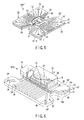
FIG. 5 is a schematic perspective view of the semiconductor package according to the modification shown inFIG. 3 with a small change. -
FIG. 6 is a schematic perspective view showing a semiconductor package according to a second embodiment of this invention, where a semiconductor accommodating portion of a package main body and a base portion are partially cut off. - A configuration of a semiconductor package SP1 according to a first embodiment of the present invention will be explained with reference to
FIG. 1 and FIG. 2 . - The semiconductor package SP1 according to the first embodiment is provided with a package
main body 20 including abase portion 10 having afirst surface 10a and asecond surface 10b positioned on a side opposite to thefirst surface 10a and configured by bringing a plurality ofthin plates device accommodating portion 18 which is provided on thefirst surface 10a and in whichsemiconductor devices 16 are accommodated. - The semiconductor
device accommodating portion 18 is provided withelectric terminals 22 electrically connected to thesemiconductor devices 16 accommodated in the semiconductordevice accommodating portion 18, and exposed to an outer surface of the semiconductordevice accommodating portion 18. - In this embodiment, peripheral
circuit mounting boards 23 each provided with a peripheral circuit for thesemiconductor device 16 are also accommodated in the semiconductordevice accommodating portion 18, and thesemiconductor devices 16 are connected to theelectric terminals 22 via wires on the peripheralcircuit mounting boards 23. - Specifically, the plurality of
thin plates FIG. 1 , only twothin plates base portion 10 may be more than two in accordance with the aspect of the present invention. - The semiconductor
device accommodating portion 18 has a cylindrical shape providing an internal space accommodating thesemiconductor devices 16 and peripheralcircuit mounting boards 23 provided with peripheral circuits relating to thesemiconductor devices 16, and surrounding a predetermined region of thefirst surface 10a of thebase portion 10. Thesemiconductor devices 16 and the peripheralcircuit mounting boards 23 are placed on the predetermined region of thefirst surface 10a. The semiconductordevice accommodating portion 18 includes alid 24 covering an opening opposite to the predetermined region of thefirst surface 10a of thebase portion 10. Thelid 24 covers the opening after thesemiconductor devices 16 and the peripheralcircuit mounting boards 23 are placed on the predetermined region of thefirst surface 10a and mutual connections among thesemiconductor devices 16, the peripheralcircuit mounting boards 23, and theelectric terminals 22 are finished, so that the internal space is sealed from the outside space. - A high
heat transfer element 26 having heat conductivity higher than that of thebase portion 10 is provided in thebase portion 10, the highheat transfer element 26 being arranged in thebase portion 10 from a heat generating site corresponding position corresponding to heat generating sites of thesemiconductor devices 16 accommodated in the semiconductor device accommodating portion 18 (a region adjacent to the heat generating sites of thesemiconductor devices 16 on thefirst surface 10a of the base portion 10) to a position in the outside of the heat generating site corresponding position, in the outside of the semiconductordevice accommodating portion 18 in this embodiment. The highheat transfer element 26 transfers heat generated by the heat generating sites of thesemiconductor devices 16 to the outside position from the heat generation site corresponding position in thebase portion 20. - In this embodiment, the high
heat transfer element 26 includes at least one combination of aflow passage 28 extending from the heat generating site corresponding position up to the outside position in thebase portion 20 and heat transfer fluid sealed in theflow passage 28 and transferring heat by its phase change. - The heat transfer fluid absorbs heat from the
semiconductor devices 16 at the heat generation site corresponding position in thebase portion 20 and changes its phase from liquid to gas, and then flows up to the outside position in theflow passages 28 by its convection. The heat transfer fluid gasified and flown by convection radiates heat at the outside position which is far from the heat generating site corresponding position and whose temperature is lower than that of the heat generating site corresponding position, and changes its phase to liquid, and then flows to the heat generating site corresponding position in theflow passage 28. As such heat transfer fluid, various kinds of ones have been widely known. - The
thin plates base portion 10 have openings each of which has a shape corresponding to theflow passage 28, and they are brought in close contact with each other and bonded to each other integrally in a state that the at least parts of openings are overlapped with each other. Theflow passages 28 configured in thebase portion 10 in this manner can be easily provided in thebase portion 10 with various numbers and various arrangements. That is, it is possible to transfer heat from the heat generating site corresponding position to a desired outside position in thebase portion 10 effectively. - When the quantity of heat generated by the
semiconductor device 16 increases, a possibility that crack or break occurs in the substrates of thesemiconductor devices 16, the peripheralcircuit mounting boards 23, or the both thereof due to differences in the coefficients of the thermal expansions between the substrate (generally, made of silicon) of thesemiconductor device 16 or the peripheral circuit mounting board 23 (generally, made of ceramic) and thebase portion 10 becomes large. In order to prevent the substrate of thesemiconductor device 16, the peripheralcircuit mounting board 23, or the both thereof from being cracked or broken, at least onethin sheet 30 having a coefficient of thermal expansion equal to or less than the coefficient of thermal expansion of the substrate of thesemiconductor device 16 or the peripheralcircuit mounting board 23 can be included in the plurality of thin plates configuring thebase portion 10. As a material for thethin plate 30, for example, molybdenum is known. The thickness or the shape of such athin plate 30 or arrangement of thethin plate 30 in thebase portion 10 is set such that an occurrence of crack or break in the substrate of thesemiconductor device 16, the peripheralcircuit mounting board 23, or the both thereof due to the difference in the coefficients of thermal expansions can be prevented and a desired heat transfer function of thebase portion 10 is not reduced. - Next, a semiconductor package SP1' according to a modification of the first embodiment described above with reference to
FIG. 1 and FIG. 2 will be explained with reference toFIG. 3 . - In this modification, the same structural members as those in the semiconductor package SP1 of the first embodiment described above with reference to
FIG. 1 and FIG. 2 are designated by the same reference numerals as those designating the structural members corresponding thereto in the semiconductor package SP1 of the first embodiment and detailed explanations thereof are omitted. - The modification is different from the first embodiment in that a ratio of each area of a first surface 10'a and a second surface 10'b of a base portion 10' to that of the semiconductor
device accommodating portion 18 is largely expanded as compared with a ratio of each area of thefirst surface 10a and thesecond surface 10b of thebase portion 10 to the semiconductordevice accommodating portion 18 in the packagemain body 20 according to the first embodiment, in order to increase a radiation function of the base portion 10' of the packagemain body 20. Further, the number of combinations of flow passages 28' and heat transfer fluids sealed in the flow passages 28' in the highheat transfer element 26 of the base portion 10' and/or the arrangement density of the combinations and/or an extending length of each combination is increased in response to the expansion of each area of the first surface 10'a and the second surface 10'b of the base portion 10'. - Here, in addition to the expansion of each area of the first surface 10'a and the second surface 10'b of the base portion 10', increase in the number of combinations of the flow passages 28' and the heat transfer fluids sealed in the flow passages 28' in the high
heat transfer element 26 and/or in the arrangement density of the combinations and/or in the extending length of each combination in the base portion 10' largely increases the radiation function of the base portion 10'. - Also in this modification, like in the case of the semiconductor package SP1 according to the first embodiment described above with reference to
FIG. 1 and FIG. 2 , in order to prevent the substrate of thesemiconductor device 16, the peripheralcircuit mounting board 23, or the both thereof from being cracked or broken by the differences in the coefficients of the thermal expansions between the substrate (generally, made of silicon) of thesemiconductor device 16 or the peripheral circuit mounting board 23 (generally, made of ceramic) and thebase portion 10, at least onethin sheet 30 having a coefficient of thermal expansion equal to or less than the coefficient of thermal expansion of the substrate of thesemiconductor device 16 or the peripheralcircuit mounting board 23 can be included in the plurality of thin plates configuring the base portion 10'. - In order to further enhance the radiation function of the base portion 10' of the package
main body 20, the semiconductor package SP1' according to the modification ofFIG. 3 can be combined with a conventional radiationperformance enhancing mechanism 32 as shown inFIG. 4 . - The radiation
performance enhancing mechanism 32 shown inFIG. 4 includes a semiconductorpackage supporting body 32a, on which the second surface 10'b of the base portion 10' of the packagemain body 20 of the semiconductor package SP1' is placed in a close contacting state with thesemiconductor supporting body 32a, and a coolingfan 32b blowing air toward the semiconductorpackage supporting body 32a, and the base portion 10' of the packagemain body 20 of the semiconductor package SP1' is fixed to the semiconductorpackage supporting body 32a by known fixing means, for example, fixing screws, preferably fixing screws made of metal having high heat conductivity (for example, copper, aluminum, copper alloy, aluminum alloy, or metal material having heat conductivity approximately equal to those of these materials), or soldering. - In the semiconductor package SP1' according to the modification of
FIG. 3 , each area of the first surface 10'a and the second surface 10'b of the base portion 10' is expanded. In this case, there is a possibility that it is difficult to connect wires (not shown) to exposed portions of theelectric terminals 22 of the semiconductorpackage accommodating portion 18. In order to clear this problem,cutouts 34 can be formed in a plurality of thin plates 12' and 14' of the base portion 10' of the semiconductor package SP1' according to the modification ofFIG. 3 to extend along extension lines of the exposed portions of theelectric terminals 22 in the outside of the semiconductordevice accommodating portion 18, as shown inFIG. 5 . Naturally, the flow passages 28' for the highheat transfer element 26 are not formed in regions of the base portion 10' where thecutouts 34 are formed. - Next, a semiconductor package SP2 according to a second embodiment of the present invention will be explained with reference to
FIG. 6 . - In this embodiment, the same structural members as those in the semiconductor package SP1 of the first embodiment described above with reference to
FIG. 1 and FIG. 2 are designated by the same reference numerals as those designating the structural members corresponding thereto in the semiconductor package SP1 of the first embodiment and detailed explanations thereof are omitted. - This embodiment is different from the first embodiment in that the high
heat transfer element 26 is configured independently of thebase portion 10 and includes at least oneheat pipe 36 arranged in thebase portion 10 to extend from the abovementioned heat generating site corresponding portion to the abovementioned outside position. - Each of the
thin plates base portion 10 has a opening OP with a shape corresponding to theheat pipe 36, and thethin plates - The
heat pipe 36 also stores heat transfer fluid in its pipe main body 36a. The heat transfer fluid in the pipe main body 36a absorbs heat from thesemiconductor device 16 at the heat generating site corresponding position in thebase portion 20 and changes its phase from liquid to gas, and then flows up to the outside position in the pipe main body 36a by convection. The heat transfer fluid gasified and flown by the convection radiates heat at the outside position which is far from the heat generating site corresponding position and whose temperature is lower than that of the heat generating site corresponding position, and changes its phase from gas to liquid, and then flows to the heat generating site corresponding position in the pipe main body 36a. As such heat transfer fluid, various kinds of ones have been widely known. - The
heat pipes 36 can be easily provided in thebase portion 10 in various numbers and various arrangements. That is, it is possible to transfer heat from the heat generating site corresponding position to a desired outside position in thebase portion 10 effectively.
Claims (8)
- A semiconductor package comprising:a package main body (20) including a base portion (10, 10') having a first surface (10a, 10'a) and a second surface (10b, 10'b) on a side opposite to the first surface, and a semiconductor device accommodating portion (18) provided on the first surface, in which a semiconductor device (16) is accommodated;electric terminals (22) provided in the semiconductor device accommodating portion, electrically connected to the semiconductor device, and exposed to an outer surface of the semiconductor device accommodating portion; anda high heat transfer element (26) having a heat conductivity higher than that of the base portion, disposed in the base portion to extend from a heat generation site corresponding position corresponding to a heat generating site of the semiconductor device (16) to a position in an outside of the heat generation site corresponding position, and transferring heat generated from the heat generating site of the semiconductor device from the heat generation site corresponding position to the outside position in the base portion,the semiconductor package characterized in thatthe base portion (10, 10') is configured by bringing a plurality of thin plates (12, 12', 14, 14') in close contact with each other to bond the thin plates to each other integrally, andthe high heat transfer element (26) includes at least one combination of a flow passage (28, 28') extending from the heat generation site corresponding position to the outside position in the base portion (10, 10') and heat transfer fluid sealed in the flow passage to transfer heat by phase-change thereof.
- The semiconductor package according to claim 1, characterized in that the thin plates (12, 12', 14, 14') of the base portion (10, 10') have openings each shape of which corresponds to the flow passage (28, 28'), and the thin plates are brought in close contact with each other and are integrally bonded to each other in a state that the openings are partially overlapped with each other.
- The semiconductor package according to claim 1, characterized in that the thin plates (12, 12', 14, 14') of the base portion (10, 10') include at least one thin plate (30) having a coefficient of thermal expansion equal to or lower than that of a substrate of the semiconductor device (16).
- The semiconductor package according to claim 1, characterized in that a peripheral circuit mounting board (23) provided with a peripheral circuit for the semiconductor device (16) is further accommodated in the semiconductor device accommodating portion (18), and
the thin plates (12, 12', 14, 14') of the base portion (10, 10') include at least one thin plate having a coefficient of thermal expansion equal to or lower than that of a substrate of the semiconductor device (16) or the peripheral circuit mounting board (23). - A semiconductor package comprising:a package main body (20) including a base portion (10) having a first surface (10a) and a second surface (10b) on a side opposite to the first surface, and a semiconductor device accommodating portion (18) provided on the first surface, in which a semiconductor device (16) is accommodated;electric terminals (22) provided in the semiconductor device accommodating portion, electrically connected to the semiconductor device, and exposed to an outer surface of the semiconductor device accommodating portion; anda high heat transfer element (26) having a heat conductivity higher than that of the base portion, disposed in the base portion to extend from a heat generation site corresponding position corresponding to a heat generating site of the semiconductor device (16) to a position in an outside of the heat generation site corresponding position, and transferring heat generated from the heat generating site of the semiconductor device from the heat generation site corresponding position to the outside position in the base portion, the semiconductor package characterized in thatthe base portion (10, 10') is configured by bringing a plurality of thin plates (12, 12', 14, 14') in close contact with each other to bond the thin plates to each other integrally, andthe high heat transfer element (26) includes at least one heat pipe (36) configured independently of the base portion (10) and arranged in the base portion (10) so as to extend from the heat generation site corresponding position to the outside position.
- The semiconductor package according to claim 5, characterized in that the thin plates (12, 14) of the base portion (10) have openings (OP) each of which has a shape corresponding to the heat pipe (36), and the thin plates (12, 14) are brought in close contact with each other and are bonded to each other in a state that the respective openings are overlapped with each other.
- The semiconductor package according to claim 5, characterized in that the thin plates (12, 14) in the base portion (10) include at least one thin plate (30) having coefficient of thermal expansion equal to or lower than that of a substrate of the semiconductor device (16).
- The semiconductor package according to claim 5, characterized in that a peripheral circuit mounting board (23) provided with a peripheral circuit for the semiconductor device (16) is further accommodated in the semiconductor device accommodating portion (18), and
the thin plates (12, 14) of the base portion (10) include at least one thin plate (30) having a coefficient of thermal expansion equal to or lower than that of a substrate of the semiconductor device (16) or the peripheral circuit mounting board (23).
Applications Claiming Priority (2)
| Application Number | Priority Date | Filing Date | Title |
|---|---|---|---|
| JP2007035356 | 2007-02-15 | ||
| PCT/JP2008/052571 WO2008099933A1 (en) | 2007-02-15 | 2008-02-15 | Semiconductor package |
Publications (2)
| Publication Number | Publication Date |
|---|---|
| EP2112688A1 true EP2112688A1 (en) | 2009-10-28 |
| EP2112688A4 EP2112688A4 (en) | 2011-09-21 |
Family
ID=39690158
Family Applications (2)
| Application Number | Title | Priority Date | Filing Date |
|---|---|---|---|
| EP08711402.1A Withdrawn EP2120261A4 (en) | 2007-02-15 | 2008-02-15 | SEMICONDUCTOR HOUSING |
| EP08711401A Withdrawn EP2112688A4 (en) | 2007-02-15 | 2008-02-15 | SEMICONDUCTOR HOUSING |
Family Applications Before (1)
| Application Number | Title | Priority Date | Filing Date |
|---|---|---|---|
| EP08711402.1A Withdrawn EP2120261A4 (en) | 2007-02-15 | 2008-02-15 | SEMICONDUCTOR HOUSING |
Country Status (6)
| Country | Link |
|---|---|
| US (3) | US7732916B2 (en) |
| EP (2) | EP2120261A4 (en) |
| JP (1) | JP5112101B2 (en) |
| KR (2) | KR101017452B1 (en) |
| TW (2) | TW200849519A (en) |
| WO (1) | WO2008099933A1 (en) |
Families Citing this family (14)
| Publication number | Priority date | Publication date | Assignee | Title |
|---|---|---|---|---|
| JP5112101B2 (en) | 2007-02-15 | 2013-01-09 | 株式会社東芝 | Semiconductor package |
| CN101689537B (en) * | 2007-04-26 | 2013-08-21 | 陶瓷技术有限责任公司 | Cooling boxes for components or circuits |
| US8305760B2 (en) * | 2008-05-16 | 2012-11-06 | Parker-Hannifin Corporation | Modular high-power drive stack cooled with vaporizable dielectric fluid |
| US9500416B2 (en) * | 2008-05-31 | 2016-11-22 | The Boeing Company | Thermal management device and method for making the same |
| US20100091477A1 (en) * | 2008-10-14 | 2010-04-15 | Kabushiki Kaisha Toshiba | Package, and fabrication method for the package |
| JP4643703B2 (en) * | 2008-11-21 | 2011-03-02 | 株式会社東芝 | Semiconductor device fixture and mounting structure thereof |
| TWM371400U (en) * | 2009-02-13 | 2009-12-21 | Asia Vital Components Co Ltd | Heat-dissipation device of communication box |
| JP5806464B2 (en) * | 2010-02-03 | 2015-11-10 | 株式会社東芝 | Semiconductor element storage package and semiconductor device using the same |
| KR200465926Y1 (en) | 2010-12-23 | 2013-03-18 | 자원전자 주식회사 | Pcb assembly |
| JP5618419B2 (en) | 2011-06-13 | 2014-11-05 | 株式会社日立製作所 | Boiling cooling system |
| US9255741B2 (en) * | 2012-01-26 | 2016-02-09 | Lear Corporation | Cooled electric assembly |
| JP5970581B1 (en) * | 2015-03-30 | 2016-08-17 | 株式会社フジクラ | Thermal diffusion plate for portable electronic devices |
| TWI655892B (en) * | 2016-05-31 | 2019-04-01 | 日商Jx金屬股份有限公司 | Structure with heat dissipation metal material, printed circuit board and electronic equipment, heat dissipation metal material |
| TWI659828B (en) * | 2016-07-27 | 2019-05-21 | 日商Jx金屬股份有限公司 | Structure with metal material for heat dissipation, printed circuit board, electronic equipment, and metal material for heat dissipation |
Family Cites Families (39)
| Publication number | Priority date | Publication date | Assignee | Title |
|---|---|---|---|---|
| US349615A (en) * | 1886-09-21 | Signor to george westing house | ||
| US346421A (en) * | 1886-07-27 | Brush | ||
| US333379A (en) * | 1885-12-29 | Fabric-turfing implement | ||
| EP0529837B1 (en) * | 1991-08-26 | 1996-05-29 | Sun Microsystems, Inc. | Method and apparatus for cooling multi-chip modules using integral heatpipe technology |
| US5801442A (en) | 1996-07-22 | 1998-09-01 | Northrop Grumman Corporation | Microchannel cooling of high power semiconductor devices |
| US6205022B1 (en) | 1997-08-27 | 2001-03-20 | Intel Corporation | Apparatus for managing heat in a computer environment or the like |
| JP2000281802A (en) * | 1999-03-30 | 2000-10-10 | Polymatech Co Ltd | Thermally conductive molded body, method for manufacturing the same, and semiconductor device |
| JP2001144237A (en) | 1999-11-18 | 2001-05-25 | Matsushita Electric Ind Co Ltd | Graphite sheet laminated thermal conductor |
| US6703703B2 (en) * | 2000-01-12 | 2004-03-09 | International Rectifier Corporation | Low cost power semiconductor module without substrate |
| JP2003037196A (en) * | 2001-07-25 | 2003-02-07 | Kyocera Corp | Optical semiconductor element storage package |
| US6935022B2 (en) * | 2001-08-28 | 2005-08-30 | Advanced Materials Technologies Pte, Ltd. | Advanced microelectronic heat dissipation package and method for its manufacture |
| CN1304807C (en) | 2001-12-13 | 2007-03-14 | 索尼公司 | Cooling device, electronic device and method of manufacturing cooling device |
| JP2003234442A (en) * | 2002-02-06 | 2003-08-22 | Hitachi Ltd | Semiconductor device and manufacturing method thereof |
| JP4057455B2 (en) * | 2002-05-08 | 2008-03-05 | 古河電気工業株式会社 | Thin sheet heat pipe |
| JP2004146413A (en) * | 2002-10-22 | 2004-05-20 | Sumitomo Electric Ind Ltd | Semiconductor element storage package and semiconductor device |
| JP2004288949A (en) | 2002-11-26 | 2004-10-14 | Kyocera Corp | Semiconductor element storage package and semiconductor device |
| JP2004221256A (en) * | 2003-01-14 | 2004-08-05 | Auto Network Gijutsu Kenkyusho:Kk | Circuit structure and method of manufacturing the same |
| JP4210908B2 (en) * | 2003-02-19 | 2009-01-21 | 株式会社デンソー | Semiconductor module |
| JP2004249589A (en) | 2003-02-20 | 2004-09-09 | Toshiba Corp | Copper-molybdenum composite material and heat sink using the same |
| JP2005064291A (en) * | 2003-08-14 | 2005-03-10 | Nissan Motor Co Ltd | Insulating sheet and semiconductor device assembly using the insulating sheet |
| KR20050025728A (en) * | 2003-09-08 | 2005-03-14 | 삼성에스디아이 주식회사 | Heat sink and display panel comprising the same |
| KR20050026133A (en) * | 2003-09-09 | 2005-03-15 | 엘지.필립스 엘시디 주식회사 | Manufacture apparatus of lcd and method thereof |
| JP4148123B2 (en) * | 2003-12-08 | 2008-09-10 | 三菱マテリアル株式会社 | Radiator and power module |
| JP4407521B2 (en) | 2004-01-20 | 2010-02-03 | 三菱マテリアル株式会社 | Insulated heat transfer structure and power module substrate |
| JP2006013420A (en) | 2004-01-28 | 2006-01-12 | Kyocera Corp | Electronic component storage package and electronic device |
| DE102004027074B4 (en) * | 2004-06-02 | 2009-06-04 | Infineon Technologies Ag | Method for producing a BGA (Ball Grid Array) component with a thin metallic cooling foil |
| JP4714434B2 (en) | 2004-07-20 | 2011-06-29 | 古河スカイ株式会社 | Heat pipe heat sink |
| US7168152B1 (en) | 2004-10-18 | 2007-01-30 | Lockheed Martin Corporation | Method for making an integrated active antenna element |
| US7401340B2 (en) * | 2004-10-21 | 2008-07-15 | Oracle International Corporation | Supporting cross-component references in an object-oriented programming system |
| US7677299B2 (en) * | 2004-11-10 | 2010-03-16 | Wen-Chun Zheng | Nearly isothermal heat pipe heat sink |
| JP4610414B2 (en) * | 2005-03-22 | 2011-01-12 | 京セラ株式会社 | Electronic component storage package, electronic device, and electronic device mounting structure |
| JP4928749B2 (en) | 2005-06-30 | 2012-05-09 | 株式会社東芝 | Cooling system |
| US7515415B2 (en) | 2006-02-02 | 2009-04-07 | Sun Microsystems, Inc. | Embedded microchannel cooling package for a central processor unit |
| JP2007311770A (en) * | 2006-04-17 | 2007-11-29 | Mitsubishi Electric Corp | Semiconductor device |
| JP4760585B2 (en) * | 2006-07-18 | 2011-08-31 | 三菱電機株式会社 | Power semiconductor device |
| JP5112101B2 (en) | 2007-02-15 | 2013-01-09 | 株式会社東芝 | Semiconductor package |
| JP5025328B2 (en) | 2007-05-16 | 2012-09-12 | 株式会社東芝 | Thermal conductor |
| JP4558012B2 (en) | 2007-07-05 | 2010-10-06 | 株式会社東芝 | Semiconductor package heat dissipation plate and semiconductor device |
| JP4504401B2 (en) | 2007-08-07 | 2010-07-14 | 株式会社東芝 | Semiconductor package |
-
2008
- 2008-02-08 JP JP2008029614A patent/JP5112101B2/en not_active Expired - Fee Related
- 2008-02-13 US US12/030,504 patent/US7732916B2/en not_active Expired - Fee Related
- 2008-02-15 EP EP08711402.1A patent/EP2120261A4/en not_active Withdrawn
- 2008-02-15 WO PCT/JP2008/052571 patent/WO2008099933A1/en not_active Ceased
- 2008-02-15 EP EP08711401A patent/EP2112688A4/en not_active Withdrawn
- 2008-02-15 TW TW097105367A patent/TW200849519A/en not_active IP Right Cessation
- 2008-02-15 KR KR1020087025034A patent/KR101017452B1/en not_active Expired - Fee Related
- 2008-02-15 KR KR1020097003384A patent/KR101066711B1/en not_active Expired - Fee Related
- 2008-02-15 TW TW097105364A patent/TWI382507B/en not_active IP Right Cessation
- 2008-10-15 US US12/252,072 patent/US7911794B2/en not_active Expired - Fee Related
-
2009
- 2009-02-26 US US12/393,680 patent/US8049316B2/en not_active Expired - Fee Related
Also Published As
| Publication number | Publication date |
|---|---|
| EP2120261A1 (en) | 2009-11-18 |
| US8049316B2 (en) | 2011-11-01 |
| US7911794B2 (en) | 2011-03-22 |
| KR101066711B1 (en) | 2011-09-21 |
| US20090091891A1 (en) | 2009-04-09 |
| EP2120261A4 (en) | 2016-10-12 |
| US7732916B2 (en) | 2010-06-08 |
| KR101017452B1 (en) | 2011-02-25 |
| US20090205806A1 (en) | 2009-08-20 |
| TWI382507B (en) | 2013-01-11 |
| JP2008227473A (en) | 2008-09-25 |
| KR20080103107A (en) | 2008-11-26 |
| JP5112101B2 (en) | 2013-01-09 |
| TW200901403A (en) | 2009-01-01 |
| KR20090033394A (en) | 2009-04-02 |
| TW200849519A (en) | 2008-12-16 |
| US20080197462A1 (en) | 2008-08-21 |
| TWI351746B (en) | 2011-11-01 |
| EP2112688A4 (en) | 2011-09-21 |
| WO2008099933A1 (en) | 2008-08-21 |
Similar Documents
| Publication | Publication Date | Title |
|---|---|---|
| US7911794B2 (en) | Semiconductor package | |
| US8299606B2 (en) | Semiconductor device includes a ceramic substrate and heat sink | |
| US7361985B2 (en) | Thermally enhanced molded package for semiconductors | |
| JP4504401B2 (en) | Semiconductor package | |
| US7745928B2 (en) | Heat dissipation plate and semiconductor device | |
| EP1848035B1 (en) | Semiconductor device with integrated heat spreader | |
| JP2573809B2 (en) | Multi-chip module with built-in electronic components | |
| JP4935220B2 (en) | Power module device | |
| JP2010251427A (en) | Semiconductor module | |
| JP5136461B2 (en) | Semiconductor device | |
| JPH11135715A (en) | Stacked mounting body | |
| EP1726197B1 (en) | An element for carrying electronic components | |
| JP6320347B2 (en) | Semiconductor device | |
| CN113950187B (en) | Planar thermal conductive copper clad laminate and packaging substrate for packaging multiple planar thermal conductive copper clad laminates | |
| JP2019161063A (en) | Heat dissipation structure of electronic component | |
| TW202614382A (en) | Integrated circuit package capable of independently assembling passive device and manufacturing method thereof | |
| JP2006024639A (en) | Semiconductor device | |
| JP2004087612A (en) | Heat dissipation member and semiconductor device using this heat dissipation member | |
| CN121011584A (en) | An irregularly shaped heat dissipation component for a multi-chip plastic-encapsulated microcircuit module | |
| CN119316984A (en) | A hot plate structure and processing method thereof | |
| JPS62118552A (en) | Cooling structure of integrated circuit | |
| JPH1117079A (en) | Semiconductor device |
Legal Events
| Date | Code | Title | Description |
|---|---|---|---|
| PUAI | Public reference made under article 153(3) epc to a published international application that has entered the european phase |
Free format text: ORIGINAL CODE: 0009012 |
|
| 17P | Request for examination filed |
Effective date: 20081014 |
|
| AK | Designated contracting states |
Kind code of ref document: A1 Designated state(s): AT BE BG CH CY CZ DE DK EE ES FI FR GB GR HR HU IE IS IT LI LT LU LV MC MT NL NO PL PT RO SE SI SK TR |
|
| RIN1 | Information on inventor provided before grant (corrected) |
Inventor name: HASEGAWA, TSUYOSHI |
|
| DAX | Request for extension of the european patent (deleted) | ||
| A4 | Supplementary search report drawn up and despatched |
Effective date: 20110824 |
|
| RIC1 | Information provided on ipc code assigned before grant |
Ipc: H01L 23/427 20060101AFI20110818BHEP |
|
| 17Q | First examination report despatched |
Effective date: 20140423 |
|
| STAA | Information on the status of an ep patent application or granted ep patent |
Free format text: STATUS: EXAMINATION IS IN PROGRESS |
|
| STAA | Information on the status of an ep patent application or granted ep patent |
Free format text: STATUS: THE APPLICATION IS DEEMED TO BE WITHDRAWN |
|
| 18D | Application deemed to be withdrawn |
Effective date: 20171006 |