EP2112533B1 - LED-Linienbeleuchtung - Google Patents
LED-Linienbeleuchtung Download PDFInfo
- Publication number
- EP2112533B1 EP2112533B1 EP09158599A EP09158599A EP2112533B1 EP 2112533 B1 EP2112533 B1 EP 2112533B1 EP 09158599 A EP09158599 A EP 09158599A EP 09158599 A EP09158599 A EP 09158599A EP 2112533 B1 EP2112533 B1 EP 2112533B1
- Authority
- EP
- European Patent Office
- Prior art keywords
- light
- optical
- led line
- detector
- line illumination
- Prior art date
- Legal status (The legal status is an assumption and is not a legal conclusion. Google has not performed a legal analysis and makes no representation as to the accuracy of the status listed.)
- Active
Links
- 239000013307 optical fiber Substances 0.000 claims abstract description 78
- 230000003287 optical effect Effects 0.000 claims abstract description 25
- 239000000835 fiber Substances 0.000 claims abstract description 20
- 238000000034 method Methods 0.000 claims abstract description 9
- 238000012544 monitoring process Methods 0.000 claims abstract description 8
- 238000012806 monitoring device Methods 0.000 claims abstract 3
- 238000005286 illumination Methods 0.000 claims description 27
- 230000002093 peripheral effect Effects 0.000 abstract description 7
- 239000003086 colorant Substances 0.000 description 6
- 230000008878 coupling Effects 0.000 description 5
- 238000010168 coupling process Methods 0.000 description 5
- 238000005859 coupling reaction Methods 0.000 description 5
- 238000009958 sewing Methods 0.000 description 5
- 239000011159 matrix material Substances 0.000 description 3
- 230000032683 aging Effects 0.000 description 2
- 230000002238 attenuated effect Effects 0.000 description 2
- 235000019504 cigarettes Nutrition 0.000 description 2
- 238000001816 cooling Methods 0.000 description 2
- 239000011162 core material Substances 0.000 description 2
- 238000001514 detection method Methods 0.000 description 2
- 238000010586 diagram Methods 0.000 description 2
- 238000009826 distribution Methods 0.000 description 2
- 239000012530 fluid Substances 0.000 description 2
- 238000007689 inspection Methods 0.000 description 2
- 229910052751 metal Inorganic materials 0.000 description 2
- 239000002184 metal Substances 0.000 description 2
- 239000004065 semiconductor Substances 0.000 description 2
- 230000035945 sensitivity Effects 0.000 description 2
- 230000003595 spectral effect Effects 0.000 description 2
- 239000000758 substrate Substances 0.000 description 2
- 238000012935 Averaging Methods 0.000 description 1
- 230000006978 adaptation Effects 0.000 description 1
- 229910052782 aluminium Inorganic materials 0.000 description 1
- XAGFODPZIPBFFR-UHFFFAOYSA-N aluminium Chemical compound [Al] XAGFODPZIPBFFR-UHFFFAOYSA-N 0.000 description 1
- 230000003321 amplification Effects 0.000 description 1
- 230000005540 biological transmission Effects 0.000 description 1
- 238000006243 chemical reaction Methods 0.000 description 1
- 238000005253 cladding Methods 0.000 description 1
- 230000004456 color vision Effects 0.000 description 1
- 238000011109 contamination Methods 0.000 description 1
- 239000000428 dust Substances 0.000 description 1
- 230000000694 effects Effects 0.000 description 1
- 238000005265 energy consumption Methods 0.000 description 1
- 238000000265 homogenisation Methods 0.000 description 1
- 230000010354 integration Effects 0.000 description 1
- 239000007788 liquid Substances 0.000 description 1
- 230000007774 longterm Effects 0.000 description 1
- 238000004519 manufacturing process Methods 0.000 description 1
- 238000003199 nucleic acid amplification method Methods 0.000 description 1
- 239000013308 plastic optical fiber Substances 0.000 description 1
- 238000005476 soldering Methods 0.000 description 1
- 230000003746 surface roughness Effects 0.000 description 1
Images


Classifications
-
- G—PHYSICS
- G02—OPTICS
- G02B—OPTICAL ELEMENTS, SYSTEMS OR APPARATUS
- G02B6/00—Light guides; Structural details of arrangements comprising light guides and other optical elements, e.g. couplings
- G02B6/0001—Light guides; Structural details of arrangements comprising light guides and other optical elements, e.g. couplings specially adapted for lighting devices or systems
- G02B6/0005—Light guides; Structural details of arrangements comprising light guides and other optical elements, e.g. couplings specially adapted for lighting devices or systems the light guides being of the fibre type
-
- G—PHYSICS
- G01—MEASURING; TESTING
- G01J—MEASUREMENT OF INTENSITY, VELOCITY, SPECTRAL CONTENT, POLARISATION, PHASE OR PULSE CHARACTERISTICS OF INFRARED, VISIBLE OR ULTRAVIOLET LIGHT; COLORIMETRY; RADIATION PYROMETRY
- G01J1/00—Photometry, e.g. photographic exposure meter
- G01J1/10—Photometry, e.g. photographic exposure meter by comparison with reference light or electric value provisionally void
- G01J1/20—Photometry, e.g. photographic exposure meter by comparison with reference light or electric value provisionally void intensity of the measured or reference value being varied to equalise their effects at the detectors, e.g. by varying incidence angle
- G01J1/28—Photometry, e.g. photographic exposure meter by comparison with reference light or electric value provisionally void intensity of the measured or reference value being varied to equalise their effects at the detectors, e.g. by varying incidence angle using variation of intensity or distance of source
- G01J1/30—Photometry, e.g. photographic exposure meter by comparison with reference light or electric value provisionally void intensity of the measured or reference value being varied to equalise their effects at the detectors, e.g. by varying incidence angle using variation of intensity or distance of source using electric radiation detectors
- G01J1/32—Photometry, e.g. photographic exposure meter by comparison with reference light or electric value provisionally void intensity of the measured or reference value being varied to equalise their effects at the detectors, e.g. by varying incidence angle using variation of intensity or distance of source using electric radiation detectors adapted for automatic variation of the measured or reference value
-
- G—PHYSICS
- G01—MEASURING; TESTING
- G01J—MEASUREMENT OF INTENSITY, VELOCITY, SPECTRAL CONTENT, POLARISATION, PHASE OR PULSE CHARACTERISTICS OF INFRARED, VISIBLE OR ULTRAVIOLET LIGHT; COLORIMETRY; RADIATION PYROMETRY
- G01J3/00—Spectrometry; Spectrophotometry; Monochromators; Measuring colours
- G01J3/02—Details
- G01J3/0205—Optical elements not provided otherwise, e.g. optical manifolds, diffusers, windows
- G01J3/0218—Optical elements not provided otherwise, e.g. optical manifolds, diffusers, windows using optical fibers
-
- G—PHYSICS
- G01—MEASURING; TESTING
- G01J—MEASUREMENT OF INTENSITY, VELOCITY, SPECTRAL CONTENT, POLARISATION, PHASE OR PULSE CHARACTERISTICS OF INFRARED, VISIBLE OR ULTRAVIOLET LIGHT; COLORIMETRY; RADIATION PYROMETRY
- G01J3/00—Spectrometry; Spectrophotometry; Monochromators; Measuring colours
- G01J3/02—Details
- G01J3/10—Arrangements of light sources specially adapted for spectrometry or colorimetry
-
- G—PHYSICS
- G01—MEASURING; TESTING
- G01J—MEASUREMENT OF INTENSITY, VELOCITY, SPECTRAL CONTENT, POLARISATION, PHASE OR PULSE CHARACTERISTICS OF INFRARED, VISIBLE OR ULTRAVIOLET LIGHT; COLORIMETRY; RADIATION PYROMETRY
- G01J3/00—Spectrometry; Spectrophotometry; Monochromators; Measuring colours
- G01J3/46—Measurement of colour; Colour measuring devices, e.g. colorimeters
- G01J3/50—Measurement of colour; Colour measuring devices, e.g. colorimeters using electric radiation detectors
- G01J3/505—Measurement of colour; Colour measuring devices, e.g. colorimeters using electric radiation detectors measuring the colour produced by lighting fixtures other than screens, monitors, displays or CRTs
Definitions
- the present invention relates to an LED line lighting.
- the invention relates to an LED line illumination, which is designed for the line-shaped illumination of a specific object in order to detect the line-shaped illuminated area by means of a line scan camera.
- the invention further relates to a method for monitoring a light beam cone of a light source, in particular an LED line illumination.
- LED line illuminators are used in various variations, in particular to illuminate objects in a line-shaped manner and to detect the line-shaped illuminated area by means of a line scan camera.
- Such LED line lighting has a plurality of light emitting diodes arranged in a row.
- white LEDs are used for scanning a color image.
- the light emitted by white light-emitting diodes varies in intensity as well as in the light color, depending on the temperature and the aging.
- the current applied to the LEDs has a considerable influence on the intensity and the light color. Therefore, it is useful when using white LEDs in one Such LED line lighting to regulate the light in terms of intensity and color.
- a reference mark is applied to the edge of a region to be illuminated, which is irradiated by the LED line illumination.
- This reference mark is detected by means of a detector and the brightness or the color values of the reference mark are determined.
- the LED line illumination is readjusted in such a way that the brightness and the color values of the reference mark correspond to a predetermined value. This corrects any fluctuations in the intensity and color of the emitted light.
- the EP 694 771 A1 describes a device for optically monitoring a flue of a steam generator.
- light to be monitored is supplied to the area to be monitored by means of light guides. From a light source, light is coupled into the optical fibers and the optical fibers point with their ends remote from the light source towards the monitoring region, so that the light is emitted at the end faces of the optical fibers. There is a set of further optical fibers arranged with the end faces in each case one end facing the monitoring area. The other ends are coupled with their front surfaces to detectors so as to be able to detect the brightness in the space to be monitored.
- the DE 195 06 809 A1 relates to a device for digitizing X-ray images.
- the x-ray image to be digitized is placed in a holder between two plates inserted.
- an LED line is provided which illuminates the X-ray image in strips, the light reflected from the image being directed by means of fiber optics onto a detector matrix arranged in parallel to the X-ray image.
- the detector matrix converts the light signals into electrical signals, so that a digital image is created from the x-ray image.
- a foot switch for controlling the rotational speed of the drive motor of a sewing machine protrudes, which is connected by an optical fiber cable with the sewing machine.
- Several optical fibers are routed in the optical fiber cable and direct light to the footswitch for a plurality of LEDs arranged in the sewing machine, which is coupled out of the optical fibers in the area of the footswitch and coupled into the set of further optical fibers to be returned to the sewing machine to be detected by corresponding detectors.
- the amount of light is adjusted by a triangular breaker plate connected to a treadle. Depending on the position of the breaker plate more or less light gets back to the sewing machine.
- the DE 196 26 448 A1 relates to an optical sensor for detecting the size and movement of particular objects.
- This sensor has a laser scanner, which is designed in such a way that a light beam is repeatedly swiveled in a plane, wherein the light beam travels along a line.
- a first laterally coupling-in optical fiber extends over the entire pivoting range of the laser beam.
- a second laterally coupling optical fiber protrudes only a small piece into this pivoting range. Both optical fibers are each connected to an optical detector, which converts the optical signal into an electrical signal.
- a body located in the pivoting range of the laser beam creates a shadow on the first optical fiber.
- the detection is carried out in such a way that first the laser beam at the second optical fiber triggers the measuring process by a short-term light pulse in the short projecting in the pivoting range of the laser beam Section of the light guide is coupled. Thereafter, light is coupled in the first light guide, unless it is shadowed by the body to be detected. This shadow is detected as a dark phase in the second light guide.
- the beginning and end of the shadow phase in the first light guide with respect to the light pulse in the second light guide provide information about the size and location of the body, if its distance from the laser scanner is known.
- the EP 570 163 A2 relates to a device for the optical inspection of cylindrical surfaces, in particular for the optical inspection of cigarettes.
- This device has light sources arranged in a row. These light sources may be ends of optical fibers or light emitting diodes. The individual light sources can be controlled differently in order to achieve the best possible illumination of the cigarettes.
- an optical position sensor for measuring a position along a one-dimensional curve emerges.
- the sensor may be used, for example, to determine the position of a boundary line between a clear and an opaque fluid.
- the sensor has a light source and a primary fiber into which the light from the light source is introduced. Parallel to the primary fiber, a secondary optical fiber is arranged, which is coupled with an end face to an optical detector which detects the light received in the secondary fiber.
- the detector is connected to a control device which evaluates the signal. If the area between these fibers is partially darkened, for example by an object or an opaque liquid, then the light received by the secondary fiber is reduced. Based on the brightness of the received light in the secondary fiber, which is detected with the detector, the position of the object or the opaque fluid can be determined.
- From the JP 2004-191214 A shows a line illumination, which has a plurality of light-emitting diodes arranged along a circular arc as the light source.
- the light of the LEDs is focused by means of a cylindrical lens on the object to be scanned.
- a movable image sensor which uses eight light-emitting diodes arranged on a substrate for illuminating the image area.
- the individual light-emitting diodes are connected in parallel on the substrate.
- Resistors are connected in series with the respective LEDs.
- the light emitting diodes are operated with the same voltage so that they emit light at the same time.
- a device for determining the color temperature (TC) of a light source is described.
- the absolute intensity of a predetermined blue spectral component and the total intensity or luminance of the light is measured. From these two values, the quotient is determined. This quotient of the blue spectral component divided by the total light intensity is in an almost linear relation to the color temperature.
- an LED line lighting is to be created, which is on the one hand simple and inexpensive and on the other hand allows integration into an optical system, so that reliable settings regarding the brightness and / or color are possible.
- Another object of the invention is to provide a method of monitoring the light beam cone of a light source, in particular LED line illumination.
- the optical detector can be connected to a control device in order to control the light-emitting diodes in dependence on the detected brightness and / or to control further optical devices depending on the detected color values in such a way that changes with respect to the color are compensated.
- the optical fiber in the light cone of the LEDs, a portion of the light emitted by the light emitting diode is laterally coupled into the optical fiber, d. h., That the light is coupled to the outer surface or peripheral surface of the optical fiber.
- the coupled light is detected at the end of the optical fiber by an optical detector, wherein the brightness and / or the color of the injected light is determined.
- the optical fiber can be arranged on the edge of the light cone of the light-emitting diodes, so that it does not affect the line-shaped emitted area.
- the coupling of the light into the optical fiber is insensitive to contamination.
- the optical fiber is a low-cost optical component that can be easily arranged in the light cone of the light-emitting diodes and thus causes a reliable, reproducible decoupling of light from the light cone and feeds the detector.
- the LED line illumination according to the invention is particularly suitable for industrial use for monitoring fast moving production lines. In such tracks, it is often difficult to provide a reference mark in the illuminated area.
- the optical fiber is disposed approximately parallel to the row of light emitting diodes, and expediently extends over at least a major portion of the length of the row of light emitting diodes.
- the optical fiber preferably has a rough surface on the peripheral surface which significantly increases the efficiency of coupling the light into the optical fiber against a smooth surface.
- One end of the optical fiber is preferably provided with a mirror.
- This mirror may be adhered to the end of the fiber, plugged into the end of the fiber in the form of a cap or vapor-deposited on the end face of the fiber.
- the provision of the mirror causes light which emerges from the fiber at this end to be reflected back into the fiber and to be available for detection at the detector. Furthermore, a better homogenization of the light is accomplished by such a mirror, since the proportion of light coupled in the region adjacent to the mirror is increased and thus attenuation losses due to the transmission in the optical fiber are counteracted.
- the inventive LED line illumination 1 comprises light emitting diodes 2 arranged in a row and a reflector 3 with which the light emitted by the light emitting diodes 2 is directed to a body 4 to be scanned.
- the scanned Body 4 is illuminated line by line with the LED line illumination 1, wherein the line-by-line illuminated area is scanned by means of a line camera 5.
- Fig. 1 shows a specific embodiment of such a reflector 3 in the side view.
- This reflector 3 has an elongated reflector plate 6, in which a mirror surface 7 is formed, which has the shape of a portion of an ellipse in cross section. This mirror surface 7 thus forms an ellipsoidal mirror.
- a vertically projecting holding web 8 is formed, which is angled with its remote from the reflector plate 6 end, so that its free edge 9 is arranged opposite to the mirror surface 7.
- the edge 9 of the holding web 8 is designed to receive a light-emitting diode line 10, which can be fastened to the edge by means of a plug connection or by means of soldering.
- the LED array 10 has a plurality of light emitting diodes 2 arranged in series.
- cooling fins 11 are formed.
- an elongate groove 12 for receiving an optical fiber 13 is formed on the side of the mirror surface 7 in the region between the mirror surface 7 and the holding web 8.
- the optical fiber 13 has two end faces and a peripheral surface or lateral surface.
- the optical fiber 13 is enclosed by the groove 12 in a range of about 2/3 of the circumferential surface and is free in the remaining area of 1/3 of the peripheral surface.
- the optical fiber 13 is a step index fiber having a cylindrical fiber core and a concentric cladding layer having a refractive index lower than that of the core material.
- Such an optical fiber is available, for example, under the trade name LUMINOUS DB-2000 (diameter: 2.0 mm) from Asahi Kasei EMD Corporation.
- the reflector 3 is formed from an elongated aluminum extruded profile.
- the optical fiber 13 preferably extends over the entire length of the reflector and protrudes at least with one end on the reflector 3.
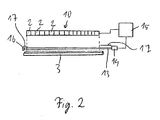
- a detector 14 ( Fig. 2 ) coupled.
- the detector 14 is preferably a multi-channel color sensor, which can detect the intensity of different color ranges independently. Such a detector is available, for example, under the type designation MCS3AS from MAZeT GmbH, Germany.
- the detector 14 is connected to a control device 15.
- the control device 15 serves to adjust the brightness of the light emitted by the light emitting diodes.
- the control device 15 may also be connected to the line camera 5 for detecting the line-by-line illuminated area in order to adapt the sensitivity of the line scan camera 5 to the color distribution of the light emitted by the light-emitting diodes.
- this end of the optical fiber 13 is ground smooth and polished and provided with a mirror 16.
- the mirror 16 may be formed as a vapor-deposited metal layer or as a metal cap bonded to the end of the optical fiber 13.
- plastic optical fibers have a certain surface roughness. This allows some of the light at the peripheral surface to be coupled into the fiber and directed in the longitudinal direction of the optical fiber 13. Light, which is guided within the optical fiber 13 in the direction of the detector 14, impinges directly on the detector 14. Light, which is initially guided in the opposite direction, is reflected by the mirror 16 and then fed to the detector 14. Part of the light is lost through loss of attenuation. The loss of attenuation is proportional to the distance traveled by the light within the optical fiber. The loss of attenuation strongly depends on the coupling of the light, which light beams, which are once directed into the region within the "critical angle" of the optical fiber are hardly attenuated due to the total reflection within the optical fiber.
- the optical fiber 13 Over a long range of the optical fiber 13 and preferably over the entire length, which corresponds to the length of the LED array 10, and light is coupled into the optical fiber 13, light from a plurality of light emitting diodes 2 and preferably from all LEDs 2 is coupled into the optical fiber 13 and the detector 14 is supplied. As a result, light from all or almost all the light-emitting diodes 2 reaches the detector 14, so that the brightness or detected color information detected by the detector represents averaged values over a multiplicity of light-emitting diodes.
- FIG. 3 shows in a block diagram of the control circuit FIG. 2 , wherein some components of the control device are shown and to simplify the drawing of the reflector 3 in FIG. 2 not shown.
- This control circuit comprises the LED line illumination 1 with a plurality of light-emitting diodes 2 arranged in a row, the light guide 13, at one end of which the detector 14 and at the other end of the mirror 16 are arranged.
- the light emitted by the light-emitting diodes 2 emitted onto the body 4 or the object 4 is directed onto the line scan camera 5 by means of an objective 18.
- the detector 14 is an RGB sensor of the MCS3AS type from MAZeT GmbH. This detector has a semiconductor sensor 19 for the colors red, green and blue.
- Each of the three semiconductor sensors 19 generates a color value r_sens, g_sens and b_sens specific to the colors red, green and blue.
- the control device 15 is provided with a color adjustment device 20 which converts the measured color values into corrected color values (r'_sens, g'_sens, b'_sens) by means of a 3 ⁇ 3 color correction matrix having nine coefficients (a1..., A9). This conversion of the color values serves to adapt the different color sensitivity of the line scan camera 5 and of the detector 14.
- the color matching device 20 simulates the color perception of the line scan camera 5 in conjunction with the detector 14.
- the corrected color values are fed to a control device 21, which receives desired values for the three colors red, green and blue (r_set, g_set, b_set) as further input parameters.
- the controller 21 determines correction values for the intensity (C 1 ) and for the colors red, green and blue (C r , C g , C b ). These correction values are output as voltage signals from the controller.
- the corresponding signal for the correction value of the light intensity (C 1 ) is supplied to a voltage / current converter 22 which is connected to the LED line illumination 1 for illuminating the intensity of the light emitted by the light emitting diodes 2.
- the line camera 5 outputs three output signals for the colors red, green and blue (r_ccd, g_ccd, b_ccd). These output signals are each supplied to a corresponding color channel amplifier 23.
- the control device 15 has, for the 3 correction values of the colors red, green and blue, adaptation elements 24 which convert the voltage signals corresponding to the correction values into suitable amplification factors for driving the color channel amplifiers 23.
- the output values of the color channel amplifiers 23 (r_korr, g_korr, b_korr) are thus corrected in accordance with the color values of the light emitted by the light emitting diodes 2 determined by the detector 14. This makes it possible to obtain 5 color images of constant quality with the line scan camera, even if the color distribution of the radiated light from the LEDs 2 changes due to aging or other influences.
- the optical fiber is preferably exposed only in a region which is arranged parallel to the light-emitting diode line 10 and has approximately the length of the light-emitting diode line 10. That is, the optical fiber 13 is provided at its ends with a cover 17, wherein the cover 17 extends from the detector 14 to the region of the LED array 10 and from the mirror 16 to the region of the LED array 10. By this cover (s) 17 is prevented at the edge area disproportionately large proportion of arranged at the edge of the light emitting diode 10 light emitting diodes 2 is coupled into the optical fiber 13. These covers 17 thus serve to homogenize the injected light.
- the optical fiber 13 may also be expedient to provide the optical fiber 13 with a cover which is designed such that the greater the distance to the detector 14, the larger the exposed surface of the optical fiber 13 is. As a result, more light is laterally coupled into the optical fiber 13 in the areas which are further away from the detector 14. This compensates for the attenuation effect in the optical fiber, because light coupled further away is attenuated more strongly than light coupled closer to the detector 14.
Landscapes
- Physics & Mathematics (AREA)
- Spectroscopy & Molecular Physics (AREA)
- General Physics & Mathematics (AREA)
- Optics & Photonics (AREA)
- Length Measuring Devices By Optical Means (AREA)
- Led Device Packages (AREA)
- Studio Devices (AREA)
Description
- Die vorliegende Erfindung betrifft eine LED-Linienbeleuchtung. Die Erfindung betrifft insbesondere eine LED-Linienbeleuchtung, die zur zeilenförmigen Beleuchtung eines bestimmten Gegenstandes ausgebildet ist, um den zeilenförmig beleuchteten Bereich mittels einer Zeilenkamera zu erfassen.
- Die Erfindung betrifft weiterhin ein Verfahren zum Überwachen eines Lichtstrahlkegels einer Lichtquelle, insbesondere einer LED-Linienbeleuchtung.
- LED-Linienbeleuchtungen werden in unterschiedlichen Variationen eingesetzt, insbesondere um Gegenstände zeilenförmig zu beleuchten und den zeilenförmig beleuchteten Bereich mittels einer Zeilenkamera zu erfassen. Eine solche LED-Linienbeleuchtung weist eine Vielzahl von in einer Reihe angeordneten Leuchtdioden auf. Zur Abtastung eines Farbbildes werden weiße Leuchtdioden verwendet. Das von weißen Leuchtdioden abgegebene Licht variiert in Abhängigkeit von der Temperatur und der Alterung in der Intensität als auch in der Lichtfarbe. Weiterhin hat der an den Leuchtdioden angelegte Strom erheblichen Einfluss auf die Intensität und die Lichtfarbe. Daher ist es zweckmäßig, bei Verwendung von weißen Leuchtdioden in einer solchen LED-Linienbeleuchtung das Licht bezüglich der Intensität und der Farbe zu regeln.
- Üblicherweise wird am Rand eines zu beleuchtenden Bereiches eine Referenzmarke angebracht, die von der LED-Linienbeleuchtung bestrahlt wird. Diese Referenzmarke wird mittels eines Detektors detektiert und es werden die Helligkeit bzw. die Farbwerte der Referenzmarke bestimmt. Die LED-Linienbeleuchtung wird derart nachgeregelt, dass die Helligkeit und die Farbwerte der Referenzmarke einem vorbestimmten Wert entsprechen. Hierdurch werden eventuelle Schwankungen in der Intensität und der Farbe des ausgestrahlten Lichtes korrigiert.
- Bei diesem System ist nachteilig, dass
- die Referenzmarke am Rande des ausgeleuchteten Bereichs den nutzbaren Bereich verringert, wodurch die mögliche Auflösung oder der Durchsatz reduziert ist,
- die Referenzmarke nur von wenigen Leuchtdioden beleuchtet wird, jedoch nicht repräsentativ für die mittleren Eigenschaften der Beleuchtung sein müssen, und
- wenige Staubkörner auf der Referenzmarke genügen, um die detektierte Helligkeit und die detektierte Farbe erheblich zu verändern, was einen erheblichen Einfluss auf die gesamte Wiedergabe hat.
- Die
EP 694 771 A1 - Die
DE 195 06 809 A1 betrifft eine Vorrichtung zur Digitalisierung von Röntgenbildern. Das zu digitalisierende Röntgenbild wird in einer Halterung zwischen zwei Platten eingelegt. Zum Abtasten des Röntgenbildes ist eine LED-Zeile vorgesehen, die das Röntgenbild streifenförmig beleuchtet, wobei das vom Bild reflektierte Licht mittels einer Faseroptik auf eine zum Röntgenbild parallel angeordnete Detektormatrix gelenkt wird. Die Detektormatrix wandelt die Lichtsignale in elektrische Signale um, so dass von dem Röntgenbild ein digitales Abbild erstellt wird. - Aus der
DE 42 00 525 A1 geht ein Fußschalter zur Steuerung der Drehzahl des Antriebsmotors einer Nähmaschine hervor, der durch ein Lichtleiterkabel mit der Nähmaschine verbunden ist. Im Lichtleiterkabel sind mehrer Lichtleiter geführt, die zum einen von mehreren in der Nähmaschine angeordneten Leuchtdioden Licht zum Fußschalter lenken, das im Bereich des Fußschalters aus den Lichtleitern ausgekoppelt wird und in den Satz weiterer Lichtleiter eingekoppelt wird, um zur Nähmaschine zurückgeführt zu werden, um dort von entsprechenden Detektoren erfasst zu werden. Im Fußschalter wird die Menge des Lichtes durch eine dreieckige Unterbrecherplatte, die mit einer Trittplatte verbunden ist, eingestellt. In Abhängigkeit von der Stellung der Unterbrecherplatte gelangt mehr oder weniger Licht zurück zur Nähmaschine. - Die
DE 196 26 448 A1 betrifft einen optischen Sensor zum Detektieren der Größe und der Bewegung bestimmter Gegenstände. Dieser Sensor weist einen Laserscanner auf, der derart ausgebildet ist, dass wiederholt ein Lichtstrahl in einer Ebene geschwenkt wird, wobei der Lichtstrahl entlang einer Linie verfährt. Eine erste seitlich einkoppelnde Lichtleitfaser erstreckt sich über den gesamten Schwenkbereich des Laserstrahls. Eine zweite seitlich einkoppelnde Lichtleitfaser ragt nur ein kleines Stück in diesen Schwenkbereich hinein. Beide Lichtleitfasern sind jeweils mit einem optischen Detektor verbunden, der das optische Signal in ein elektrisches Signal umsetzt. Ein Körper, der sich in dem Schwenkbereich des Laserstrahls befindet, erzeugt auf dem ersten Lichtleiter einen Schatten. Die Detektion erfolgt derart, dass zunächst der Laserstrahl am zweiten Lichtleiter den Messvorgang triggert, indem ein kurzzeitiger Lichtpuls in den kurzen in den Schwenkbereich des Laserstrahls vorstehenden Abschnitt des Lichtleiters eingekoppelt wird. Danach wird im ersten Lichtleiter Licht eingekoppelt, sofern er nicht durch den zu detektierenden Körper beschattet wird. Dieser Schatten wird als Dunkelphase im zweiten Lichtleiter detektiert. Der Beginn und das Ende der Schattenphase im ersten Lichtleiter bezüglich des Lichtpulses im zweiten Lichtleiter ergeben eine Aussage über die Größe und den Ort des Körpers, wenn dessen Abstand zum Laserscanner bekannt ist. - Die
EP 570 163 A2 - Aus der
US 7,049,622 B1 geht ein optischer Positionssensor zum Messen einer Position entlang einer eindimensionalen Kurve hervor. Der Sensor kann zum Beispiel zum Bestimmen der Position einer Grenzlinie zwischen einem klaren und einem opaken Fluid verwendet werden. Der Sensor weist eine Lichtquelle auf und eine primäre Faser, in die das Licht der Lichtquelle eingeführt wird. Parallel zur primären Faser ist eine sekundäre Lichtleitfaser angeordnet, die mit einer Stirnseite an einen optischen Detektor gekoppelt ist, der das in der sekundären Faser aufgenommene Licht detektiert. Der Detektor ist mit einer Steuereinrichtung verbunden, die das Signal auswertet. Ist der Bereich zwischen diesen Fasern abschnittsweise abgedunkelt, beispielsweise durch einen Gegenstand oder eine opake Flüssigkeit, dann vermindert sich das von der sekundären Faser empfangene Licht. Anhand der Helligkeit des in der sekundären Faser empfangenen Lichtes, die mit dem Detektor detektiert wird, kann die Position des Gegenstandes beziehungsweise des opaken Fluides ermittelt werden. - Aus der
JP 2005-341602 A - Aus der
JP 2004-191214 A - In der
JP 11-017887 A - In der
WO 2005/008196 A2 wird eine Vorrichtung zum Bestimmen der Farbtemperatur (TC) einer Lichtquelle beschrieben. Bei diesem Verfahren wird die absolute Intensität einer vorbestimmten blauen Spektralkomponente sowie die Gesamtintensität beziehungsweise Luminanz des Lichtes gemessen. Aus diesen beiden Werten wird der Quotient bestimmt. Dieser Quotient aus der blauen Spektralkomponente geteilt durch die gesamte Lichtintensität steht in einer fast linearen Beziehung zur Farbtemperatur. - In der
US 5 491 336 wird eine Linienlichtquelle offenbart, bei der Licht aus einer Anzahl in Reihe angeordneter Lichtquellen über einen Reflektor auf ein Objekt umgelenkt wird. - Mit der Erfindung soll eine LED-Linienbeleuchtung geschaffen werden, die einerseits einfach und kostengünstig ausgebildet ist und andererseits eine Integration in ein optisches System erlaubt, so dass zuverlässig Einstellungen bzgl. der Helligkeit und/oder Farbe möglich sind.
- Eine weitere Aufgabe der Erfindung ist die Schaffung eines Verfahrens zum Überwachen des Lichtstrahlkegels einer Lichtquelle, insbesondere einer LED-Linienbeleuchtung.
- Die Aufgabe wird durch eine LED-Linienbeleuchtung mit dem Merkmal des Anspruchs 1 und durch ein Verfahren mit den Merkmalen des Anspruchs 13 gelöst. Vorteilhafte Ausgestaltungen sind in den jeweiligen Unteransprüchen angegeben.
- Die erfindungsgemäße LED-Linienbeleuchtung umfasst
- in einer Reihe angeordnete Leuchtdioden zum zeilenweisen Beleuchten eines Gegenstandes,
- einen Reflektor (3) mit welchem das von den Leuchtdioden (2) abgestrahlte Licht auf den Gegenstand (4) gelenkt wird,
- eine Lichtleitfaser, die im Bereich des von den Leuchtdioden ausgestrahlten Lichtes angeordnet ist, so dass ein Teil dieses Lichtes in die Lichtleitfaser seitlich eingekoppelt wird,
- einen optischen Detektor zum Detektieren der Helligkeit und/oder der Farbe des in die Lichtleitfaser eingekoppelten Lichtes.
- Der optische Detektor kann mit einer Steuereinrichtung verbunden werden, um in Abhängigkeit der detektierten Helligkeit die Leuchtdioden anzusteuern und/oder in Abhängigkeit der detektierten Farbwerte weitere optische Einrichtung derart anzusteuern, dass Veränderungen bzgl. der Farbe kompensiert werden.
- Durch das Vorsehen der Lichtleitfaser im Lichtkegel der Leuchtdioden wird ein Teil des von den Leuchtdioden abgestrahlten Lichtes seitlich in die Lichtleitfaser eingekoppelt, d. h., dass das Licht an der Mantelfläche bzw. Umfangsfläche der Lichtleitfaser eingekoppelt wird. Das eingekoppelte Licht wird am Ende der Lichtleitfaser von einem optischen Detektor detektiert, wobei die Helligkeit und/oder die Farbe des eingekoppelten Lichtes bestimmt wird.
- Durch das Vorsehen einer Lichtleitfaser wird Licht von einer Vielzahl von Leuchtdioden dem Detektor zugeführt. Hierdurch wird eine Mittelung des Lichtes unterschiedlicher Leuchtdioden erzielt.
- Die Lichtleitfaser kann am Rande des Lichtkegels der Leuchtdioden angeordnet sein, so dass sie den zeilenförmig ausgestrahlten Bereich nicht beeinträchtigt. Die Einkopplung des Lichtes in die Lichtleitfaser ist gegenüber Verschmutzung unempfindlich. Die Lichtleitfaser ist ein kostengünstiges optisches Bauteil, das einfach im Lichtkegel der Leuchtdioden angeordnet werden kann und so eine zuverlässige, reproduzierbare Auskopplung von Licht aus dem Lichtkegel bewirkt und dem Detektor zuführt.
- Die erfindungsgemäße LED-Linienbeleuchtung ist insbesondere für den industriellen Einsatz zum Überwachen von sich schnell bewegenden Fertigungsbahnen geeignet. Bei solchen Bahnen ist es oft schwierig, im ausgeleuchteten Bereich eine Referenzmarke vorzusehen.
- Vorzugsweise wird die Lichtleitfaser etwa parallel zur Reihe der Leuchtdioden angeordnet, und erstreckt sich zweckmäßigerweise über zumindest einen Großteil der Länge der Reihe von Leuchtdioden.
- Die Lichtleitfaser weist vorzugsweise an der Umfangsfläche eine raue Oberfläche auf, die die Effizienz zur Einkopplung des Lichtes in die Lichtleitfaser gegenüber einer glatten Oberfläche erheblich steigert.
- Ein Ende der Lichtleitfaser ist vorzugsweise mit einem Spiegel versehen. Dieser Spiegel kann an dem Ende der Faser festgeklebt sein, in Form einer Kappe auf das Ende der Faser gesteckt sein oder auf die Stirnfläche der Faser aufgedampft sein. Das Vorsehen des Spiegels bewirkt zum einen, dass Licht, das an diesem Ende aus der Faser austritt, wieder in die Faser zurück reflektiert wird und zur Detektion am Detektor zur Verfügung steht. Des Weiteren wird durch einen solchen Spiegel eine bessere Homogenisierung des Lichtes bewerkstelligt, da der Anteil des im Bereich benachbart zum Spiegel eingekoppelten Lichtes gesteigert wird und so Dämpfungsverlusten aufgrund der Übertragung in der Lichtleitfaser entgegengewirkt wird.
- Die Erfindung wird nachfolgend beispielhaft anhand eines in den Zeichnungen dargestellten Ausführungsbeispiels erläutert. Die Zeichnungen zeigen:
- Fig. 1
- eine LED-Linienbeleuchtung mit einem Reflektor in einer Stirnansicht,
- Fig. 2
- schematisch den Aufbau eines Regelkreises in den die erfindungsgemäße LED-Linienbeleuchtung integriert ist, und
- Fig. 3
- den Regelkreis aus
Fig. 2 in einem Blockschaltbild. - Die erfindungsgemäße LED-Linienbeleuchtung 1 umfasst in einer Reihe angeordnete Leuchtdioden 2 und einen Reflektor 3, mit welchem das von den Leuchtdioden 2 abgestrahlte Licht auf einen abzutastenden Körper 4 gelenkt wird. Der abzutastende Körper 4 wird mit der LED-Linienbeleuchtung 1 zeilenweise ausgeleuchtet, wobei der zeilenweise ausgeleuchtete Bereich mittels einer Zeilenkamera 5 abgetastet wird.
-
Fig. 1 zeigt ein spezielles Ausführungsbeispiel eines solchen Reflektors 3 in der Seitenansicht. Dieser Reflektor 3 weist eine langgestreckte Reflektorplatte 6 auf, in welcher eine Spiegelfläche 7 ausgebildet ist, die im Querschnitt die Form eines Abschnitts einer Ellipse besitzt. Diese Spiegelfläche 7 bildet somit einen Ellipsoid-Spiegel. An einem Rand der Reflektorplatte 6 ist ein senkrecht abstehender Haltesteg 8 ausgebildet, der mit seinem von der Reflektorplatte 6 entfernten Ende derart abgewinkelt ist, so dass sein freier Rand 9 zur Spiegelfläche 7 gegenüberliegend angeordnet ist. Der Rand 9 des Haltestegs 8 ist zur Aufnahme einer Leuchtdiodenzeile 10 ausgebildet, die an dem Rand mittels einer Steckverbindung oder mittels Löten befestigbar ist. Die Leuchtdiodenzeile 10 weist mehrere in Reihe angeordnete Leuchtdioden 2 auf. - An der von der Reflektorplatte 6 abgewandten Seite des Haltestegs 8 sind Kühlrippen 11 angeformt.
- An der Reflektorplatte 6 ist auf der Seite der Spiegelfläche 7 im Bereich zwischen der Spiegelfläche 7 und dem Haltesteg 8 eine langgestreckte Nut 12 zur Aufnahme einer Lichtleitfaser 13 ausgebildet. Die Lichtleitfaser 13 weist zwei Stirnflächen und eine Umfangsfläche bzw. Mantelfläche auf. Die Lichtleitfaser 13 wird von der Nut 12 in einem Bereich von etwa 2/3 der Umfangsfläche eingeschlossen und liegt im übrigen Bereich von 1/3 von der Umfangsfläche frei.
- Im vorliegenden Ausführungsbeispiel ist die Lichtleitfaser 13 eine Stufen-Index-Faser mit einem zylindrischen Faserkern und einer konzentrischen Mantelschicht, die einen Brechungsindex niedriger als der des Kernmaterials aufweist. Eine solche Lichtleitfaser ist beispielsweise unter dem Handelsnamen LUMINOUS DB-2000 (Durchmesser: 2,0 mm) von der Firma Asahi Kasei EMD Corporation erhältlich.
- Der Reflektor 3 ist aus einem langgestreckten Aluminiumstrangprofil ausgebildet. Die Lichtleitfaser 13 erstreckt sich vorzugsweise über die gesamte Länge des Reflektors und steht zumindest mit einem Ende am Reflektor 3 vor. An dieses Ende ist ein Detektor 14 (
Fig. 2 ) gekoppelt. Der Detektor 14 ist vorzugsweise ein mehrkanaliger Farbsensor, der die Intensität unterschiedlicher Farbbereiche unabhängig voneinander erfassen kann. Ein solcher Detektor ist beispielsweise unter der Typbezeichnung MCS3AS von der Firma MAZeT GmbH, Deutschland, erhältlich. Der Detektor 14 ist mit einer Steuereinrichtung 15 verbunden. Die Steuereinrichtung 15 dient zur Einstellung der Helligkeit des von den Leuchtdioden abgestrahlten Lichtes. Die Steuereinrichtung 15 kann auch mit der Zeilenkamera 5 zum Detektieren des zeilenweise ausgeleuchteten Bereichs verbunden sein, um die Empfindlichkeit der Zeilenkamera 5 an die Farbverteilung des von den Leuchtdioden abgestrahlten Lichtes anzupassen. - An dem vom Detektor 14 entfernten Ende der Lichtleitfaser 13 ist diese vorzugsweise verspiegelt. Hierzu ist dieses Ende der Lichtleitfaser 13 glatt geschliffen und poliert und mit einem Spiegel 16 versehen. Der Spiegel 16 kann als aufgedampfte Metallschicht oder als Metallkappe, die mit dem Ende der Lichtleitfaser 13 verklebt ist, ausgebildet sein.
- Nachfolgend wird die Auskopplung eines Teils des Lichtes mittels der Lichtleitfaser 13 näher erläutert:
- Die Leuchtdiodenzeile 10 strahlt Licht in einem vorbestimmten Lichtkegel aus. Dieser Lichtkegel überdeckt die Spiegelfläche 7 des Reflektors 3 sowie den in der Nut 12 freiliegenden Bereich der Umfangsfläche der Lichtleitfaser 13.
- Handelsübliche Lichtleitfasern aus Kunststoff besitzen eine gewisse Oberflächenrauigkeit. Dies ermöglicht es, dass ein gewisser Anteil des Lichtes an der Umfangsfläche in die Faser eingekoppelt wird und in Längsrichtung der Lichtleitfaser 13 geleitet wird. Licht, das innerhalb der Lichtleitfaser 13 in Richtung zum Detektor 14 geführt wird, trifft unmittelbar auf den Detektor 14. Licht, das zunächst in die entgegengesetzte Richtung geführt wird, wird vom Spiegel 16 reflektiert und dann auch dem Detektor 14 zugeführt. Ein Teil des Lichtes geht durch Dämpfungsverluste verloren. Die Dämpfungsverluste sind proportional zur Wegstrecke, die das Licht innerhalb der Lichtleitfaser zurück legt. Die Dämpfungsverluste hängen stark von der Einkopplung des Lichtes ab, wobei Lichtstrahlen, die einmal in den Bereich innerhalb des "kritischen Winkels" der Lichtleitfaser gelenkt werden aufgrund der Totalreflektion innerhalb der Lichtleitfaser kaum gedämpft werden.
- Deshalb kann es auch zweckmäßig sein, anstelle einer Stufen-Index-Faser eine Gradienten-Index-Faser zu verwenden, die eine gleichmäßigere Einkopplung des Lichtes bewirkt.
- Über einen langen Bereich der Lichtleitfaser 13 und vorzugsweise über die gesamte Länge, die der Länge der Leuchtdiodenzeile 10 entspricht, und Licht in die Lichtleitfaser 13 eingekoppelt wird, wird Licht von einer Vielzahl der Leuchtdioden 2 und vorzugsweise von allen Leuchtdioden 2 in die Lichtleitfaser 13 eingekoppelt und dem Detektor 14 zugeführt. Hierdurch gelangt an den Detektor 14 Licht von allen oder fast allen Leuchtdioden 2, so dass die vom Detektor erfasste Helligkeit bzw. erfassten Farbinformationen über eine Vielzahl von Leuchtdioden gemittelte Werte darstellen.
-
Figur 3 zeigt in einem Blockschaltbild den Regelkreis ausFigur 2 , wobei einige Komponenten der Steuereinrichtung gezeigt sind und zur Vereinfachung der Zeichnung der Reflektor 3 inFigur 2 nicht dargestellt ist. Dieser Regelkreis umfasst die LED-Linienbeleuchtung 1 mit mehreren in einer Reihe angeordneter Leuchtdioden 2, den Lichtleiter 13, an dessen einem Ende der Detektor 14 und an dessen anderem Ende der Spiegel 16 angeordnet sind. Das auf den Körper 4 bzw. das Objekt 4 abgestrahlte Licht der Leuchtdioden 2 wird mittels eines Objektivs 18 auf die Zeilenkamera 5 gelenkt. Der Detektor 14 ist ein RGB-Sensor des Typs MCS3AS der Firma MAZeT GmbH. Dieser Detektor weist für die Farben Rot, Grün und Blau jeweils einen Halbleitersensor 19 auf. Jeder der drei Halbleitersensoren 19 erzeugt ein für die Farben Rot, Grün und Blau spezifischen Farbwert r_sens, g_sens und b_sens. Die Steuereinrichtung 15 ist mit einer Farbanpassungseinrichtung 20 versehen, die mittels einer 3x3-Farbkorrekturmatrix mit neun Koeffizienten (a1..., a9) die gemessenen Farbwerte in korrigierte Farbwerte (r'_sens, g'_sens, b'_sens) umsetzt. Diese Umsetzung der Farbwerte dient zur Anpassung der unterschiedlichen farblichen Sensitivität der Zeilenkamera 5 und des Detektors 14. Durch die Farbanpassungseinrichtung 20 wird in Verbindung mit dem Detektor 14 die Farbwahrnehmung der Zeilenkamera 5 simuliert. - Die korrigierten Farbwerte werden einer Regeleinrichtung 21 zugeführt, die als weitere Eingangsparameter Sollwerte für die drei Farben Rot, Grün und Blau (r_soll, g_soll, b_soll) erhält. Die Regeleinrichtung 21 bestimmt Korrekturwerte für die Intensität (C1) und für die Farben Rot, Grün und Blau (Cr, Cg, Cb). Diese Korrekturwerte werden als Spannungssignale von der Regeleinrichtung ausgegeben. Das entsprechende Signal für den Korrekturwert der Lichtintensität (C1) wird einem Spannungs/Stromwandler 22 zugeführt, der mit der LED-Linienbeleuchtung 1 zum Anstrahlen der Intensität des von den Leuchtdioden 2 abgestrahlten Lichtes verbunden ist.
- Die Zeilenkamera 5 gibt drei Ausgangssignale für die Farben Rot, Grün und Blau (r_ccd, g_ccd, b_ccd) aus. Diese Ausgangssignale werden jeweils einem entsprechenden Farbkanalverstärker 23 zugeführt.
- Die Steuereinrichtung 15 weist für die 3 Korrekturwerte der Farben Rot, Grün und Blau Anpassungselemente 24 auf, die die den Korrekturwerte entsprechenden Spannungssignale in geeignete Verstärkungsfaktoren zum Ansteuern der Farbkanalverstärker 23 umsetzen. Die Ausgangswerte der Farbkanalverstärker 23 (r_korr, g_korr, b_korr) werden somit entsprechend den mittels des Detektors 14 ermittelten Farbwerten des von den Leuchtdioden 2 ausgestrahlten Lichtes korrigiert. Hierdurch ist es möglich, mit der Zeilenkamera 5 Farbbilder konstanter Qualität zu erhalten, auch wenn sich aufgrund von Alterungserscheinungen oder sonstiger Einflüsse die Farbverteilung des von den Leuchtdioden 2 abgestrahlten Lichtes verändert.
- Mit der erfindungsgemäßen LED-Linienbeleuchtung 1 wird eine langzeitstabile Farbwiedergabe erzielt, die unabhängig von Verschmutzung und einfach und kostengünstig zu realisieren ist.
- Vorzugsweise liegt die Lichtleitfaser nur in einem Bereich frei, der parallel zur Leuchtdiodenzeile 10 angeordnet ist und etwa die Länge der Leuchtdiodenzeile 10 aufweist. D.h., dass die Lichtleitfaser 13 an ihren Enden mit einer Abdeckung 17 versehen ist, wobei sich die Abdeckung 17 vom Detektor 14 bis zum Bereich der Leuchtdiodenzeile 10 bzw. vom Spiegel 16 bis zum Bereich der Leuchtdiodenzeile 10 erstreckt. Durch diese Abdeckung(en) 17 wird verhindert, dass am Randbereich ein überproportional großer Anteil der am Rand der Leuchtdiodenzeile 10 angeordneten Leuchtdioden 2 in die Lichtleitfaser 13 eingekoppelt wird. Diese Abdeckungen 17 dienen somit zur Homogenisierung des eingekoppelten Lichtes.
- Im Rahmen der Erfindung kann es auch zweckmäßig sein, die Lichtleitfaser 13 mit einer Abdeckung zu versehen, die derart ausgebildet ist, dass je größer der Abstand zum Detektor 14 ist, desto größer die freiliegende Fläche der Lichtleitfaser 13 ist. Hierdurch wird in den Bereichen, die von dem Detektor 14 weiter entfernt sind, mehr Licht seitlich in die Lichtleitfaser 13 eingekoppelt. Dies kompensiert den Dämpfungseffekt in der Lichtleitfaser, denn weiter entfernt eingekoppeltes Licht wird stärker als näher am Detektor 14 eingekoppeltes Licht gedämpft.
-
- 1
- LED-Linienbeleuchtung
- 2
- Leuchtdiode
- 3
- Reflektor
- 4
- Körper
- 5
- Zeilenkamera
- 6
- Reflektorplatte
- 7
- Spiegelfläche
- 8
- Haltesteg
- 9
- Rand
- 10
- Leuchtdiodenzeile
- 11
- Kühlrippe
- 12
- Nut
- 13
- Lichtleitfaser
- 14
- Detektor
- 15
- Steuereinrichtung
- 16
- Spiegel
- 17
- Abdeckung
Claims (14)
- LED-Linienbeleuchtung, umfassend- in einer Reihe angeordnete Leuchtdioden (2) zum zeilenweisen Beleuchten eines Gegenstandes (4),- einen Reflektor (3), mit welchem das von den Leuchtdioden (2) abgestrahlte Licht auf den Gegenstand (4) gelenkt wird,- eine Lichtleitfaser (13), die im Bereich des von den Leuchtdioden ausgestrahlten Lichtes angeordnet ist, so dass ein Teil dieses Lichtes seitlich in die Lichtleitfaser (13) eingekoppelt wird, und- einen optischen Detektor (14) zum Detektieren der Helligkeit und/oder der Farbe des in die Lichtleitfaser (13) eingekoppelten Lichtes.
- LED-Linienbeleuchtung nach Anspruch 1,
dadurch gekennzeichnet,
dass die Lichtleitfaser (13) etwa parallel zur Reihe der Leuchtdioden (2) angeordnet ist. - LED-Linienbeleuchtung nach Anspruch 1 oder 2,
dadurch gekennzeichnet,
dass die Lichtleitfaser (13) eine Stufen-Index-Faser oder eine Gradienten-Index-Faser ist. - LED-Linienbeleuchtung nach einem der Ansprüche 1 bis 3,
dadurch gekennzeichnet,
dass ein Ende der Lichtleitfaser (13) mit einem Spiegel (16) versehen ist und dass am anderen Ende der Lichtleitfaser (13) der optische Detektor (14) angeordnet ist. - LED-Linienbeleuchtung nach einem der Ansprüche 1 bis 4,
dadurch gekennzeichnet,
dass der optische Detektor (14) ein mehrkanaliger Farbsensor ist. - LED-Linienbeleuchtung nach einem der Ansprüche 1 bis 5,
dadurch gekennzeichnet,
dass die Steuereinrichtung (15) mehrere Farbkanalverstärker umfasst. - LED-Linienbeleuchtung nach einem der Ansprüche 1 bis 6,
dadurch gekennzeichnet,
dass die Lichtleitfaser (13) im zum Detektor (14) benachbarten Bereich abgedeckt ist. - LED-Linienbeleuchtung nach einem der Ansprüche 1 bis 7,
dadurch gekennzeichnet,
dass die Lichtleitfaser (13) eine Abdeckung aufweist, die derart ausgebildet ist, so dass je größer der Abstand zum Detektor ist, desto größer die frei liegende Fläche der Lichtleitfaser (13) ist. - LED-Linienbeleuchtung nach einem der Ansprüche 1 bis 8,
dadurch gekennzeichnet,
dass eine Steuereinrichtung (15) zum Ansteuern der Helligkeit nach Maßgabe der vom optischen Detektor (14) detektierten Helligkeit vorgesehen ist. - Optische Überwachungseinrichtung mit einer Kamera (5), die einen mittels einer LED-Linienbeleuchtung nach einem der Ansprüche 1 bis 9 ausgeleuchteten Bereich überwacht, wobei eine Steuereinrichtung vorgesehen ist, die in Abhängigkeit der vom optischen Detektor (14) der LED-Linienbeleuchtung ermittelten Farbwerte die Ausgabe der Bildsignale der Kamera (5) korrigiert.
- Überwachungsvorrichtung nach Anspruch 10,
dadurch gekennzeichnet,
dass die Steuereinrichtung (15) auch zum Einstellen der Intensität des von den Leuchtdioden (2) abgestrahlten Lichtes ausgebildet ist. - Verfahren zum Überwachen eines Lichtstrahlkegels einer Lichtquelle einer LED-Linienbeleuchtung, wobei
mit einem Reflektor (3) Licht auf einen zu beleuchtenden Gegenstand gelenkt wird und eine Lichtleitfaser (13) verwendet wird, um einen Teil des Lichtes des Lichtstrahlkegels zu einem optischen Detektor (14) zu leiten, indem die Lichtleitfaser (13) derart in den Lichtstrahlkegel angeordnet ist, dass Licht an der Umfangsfläche der Lichtleitfaser (13) eingekoppelt und zum optischen Detektor (14) geleitet wird, und der optische Detektor (14) die Helligkeit und/oder Farbe des Lichtes detektiert. - Verfahren nach Anspruch 12,
dadurch gekennzeichnet,
dass nach Maßgabe der detektierten Helligkeit und/oder Farbe die Lichtquelle angesteuert wird. - Verfahren nach Anspruch 12,
dadurch gekennzeichnet,
dass mittels einer Kamera (5) ein Bild eines von der Lichtquelle ausgeleuchteten Gegenstandes aufgenommen wird und das von der Kamera aufgenommene Bild nach Maßgabe der detektierten Helligkeit und/oder Farbe die Lichtquelle korrigiert wird.
Applications Claiming Priority (1)
| Application Number | Priority Date | Filing Date | Title |
|---|---|---|---|
| DE102008020382A DE102008020382A1 (de) | 2008-04-23 | 2008-04-23 | LED-Linienbeleuchtung |
Publications (2)
| Publication Number | Publication Date |
|---|---|
| EP2112533A1 EP2112533A1 (de) | 2009-10-28 |
| EP2112533B1 true EP2112533B1 (de) | 2011-10-26 |
Family
ID=40886610
Family Applications (1)
| Application Number | Title | Priority Date | Filing Date |
|---|---|---|---|
| EP09158599A Active EP2112533B1 (de) | 2008-04-23 | 2009-04-23 | LED-Linienbeleuchtung |
Country Status (3)
| Country | Link |
|---|---|
| EP (1) | EP2112533B1 (de) |
| AT (1) | ATE530934T1 (de) |
| DE (1) | DE102008020382A1 (de) |
Families Citing this family (1)
| Publication number | Priority date | Publication date | Assignee | Title |
|---|---|---|---|---|
| EP2579682B1 (de) | 2011-10-07 | 2015-09-09 | Goodrich Lighting Systems GmbH | Verfahren zur Steuerung eines Flugzeuglichts |
Citations (1)
| Publication number | Priority date | Publication date | Assignee | Title |
|---|---|---|---|---|
| US5491336A (en) * | 1993-12-22 | 1996-02-13 | Unisys Corporation | Document illumination with Lambertian cavity |
Family Cites Families (11)
| Publication number | Priority date | Publication date | Assignee | Title |
|---|---|---|---|---|
| CH682678A5 (de) * | 1991-03-14 | 1993-10-29 | Gegauf Fritz Ag | Steuervorrichtung für den Antriebsmotor einer Nähmaschine. |
| ES2120481T3 (es) | 1992-05-15 | 1998-11-01 | Philip Morris Prod | Aparato y metodo para inspeccionar opticamente superficies cilindricas. |
| DE69514051T2 (de) * | 1994-06-29 | 2000-08-31 | Orfeus Combustion Eng Gmbh | Vorrichtung zur optischen Überwachung |
| DE4422414A1 (de) | 1994-06-29 | 1996-01-04 | Bfi Entsorgungstech | Optische Überwachungsanordnung |
| DE19506809C2 (de) * | 1995-02-27 | 1999-09-30 | Siemens Ag | Vorrichtung zur Digitalisierung von Röntgenbildern |
| DE19626448A1 (de) * | 1996-06-20 | 1998-01-02 | Ingbuero Fuer Spezialtechnik I | Optische Fasersensoren mit lateraler Auflösung |
| JPH1117887A (ja) * | 1997-06-27 | 1999-01-22 | Rohm Co Ltd | 携帯用密着型イメージセンサ |
| JP2004191214A (ja) * | 2002-12-12 | 2004-07-08 | Kokusai Gijutsu Kaihatsu Co Ltd | ライン照明装置及びライン照明装置を用いた検査装置 |
| CN1826513A (zh) * | 2003-07-22 | 2006-08-30 | 皇家飞利浦电子股份有限公司 | 用于测量色温的方法和设备 |
| US7049622B1 (en) * | 2004-04-09 | 2006-05-23 | Sandia Corporation | Optical position sensor for determining the interface between a clear and an opaque fluid |
| JP3905545B2 (ja) * | 2005-06-10 | 2007-04-18 | シチズン電子株式会社 | イメージスキャナー装置 |
-
2008
- 2008-04-23 DE DE102008020382A patent/DE102008020382A1/de not_active Withdrawn
-
2009
- 2009-04-23 AT AT09158599T patent/ATE530934T1/de active
- 2009-04-23 EP EP09158599A patent/EP2112533B1/de active Active
Patent Citations (1)
| Publication number | Priority date | Publication date | Assignee | Title |
|---|---|---|---|---|
| US5491336A (en) * | 1993-12-22 | 1996-02-13 | Unisys Corporation | Document illumination with Lambertian cavity |
Also Published As
| Publication number | Publication date |
|---|---|
| ATE530934T1 (de) | 2011-11-15 |
| DE102008020382A1 (de) | 2009-11-12 |
| EP2112533A1 (de) | 2009-10-28 |
Similar Documents
| Publication | Publication Date | Title |
|---|---|---|
| EP1730500B1 (de) | Optische systeme zur erzeugung eines beleuchtungsstreifens | |
| EP1304019B1 (de) | Beleuchtungsvorrichtung mit lichtemittierenden dioden (led), beleuchtungsverfahren und verfahren zur bildaufzeichnung mit derartiger led-beleuchtungsvorrichtung | |
| EP1314972B1 (de) | Spektralphotometer und Verwendung desselben | |
| EP1655600B1 (de) | Garnsensor | |
| DE10291122B4 (de) | Lesegerät mit einer Bildaufnahmeeinheit zum Lesen eines Codes und Verfahren zum Lesen eines Codes | |
| EP1727678B1 (de) | Optisches system zur erzeugung eines beleuchteten gebildes | |
| DE10022597B4 (de) | Vorrichtung zum Erfassen der Randkante und/oder einer Markierung einer laufenden Warenbahn | |
| EP2276585B1 (de) | Verfahren zum optischen detektieren von bewegten objekten | |
| DE10330003B4 (de) | Vorrichtung, Verfahren und Computerprogramm zur Wafer-Inspektion | |
| DE102009044151A1 (de) | Vorrichtung zur optischen Waferinspektion | |
| DE19532877A1 (de) | Vorrichtung zur linienförmigen Beleuchtung von Blattgut, wie z. B. Banknoten oder Wertpapiere | |
| DE10000030A1 (de) | Kamerasystem für die Bearbeitung von Dokumenten | |
| DE102005031647A1 (de) | Beleuchtungsvorrichtung zur Dunkelfeldbeleuchtung für eine optische Testvorrichtung und Verfahren zum optischen Abtasten eines Objektes | |
| EP2112533B1 (de) | LED-Linienbeleuchtung | |
| DE10137043A1 (de) | Vorrichtung zur Untersuchung von Wertdokumenten | |
| EP2253948A1 (de) | Vorrichtung zum optischen Untersuchen eines Gegenstandes | |
| EP2294368B1 (de) | Verfahren sowie vorrichtung zur erfassung des kantenprofils von flaschen oder dergleichen behältern | |
| AT508060A1 (de) | Verfahren, beleuchtungseinrichtung und system zum optischen detektieren von bewegten objekten | |
| DE10161486B4 (de) | Konfokaler Liniensensor | |
| DE112015001325T5 (de) | Beleuchtungsvorrichtung und Bild-Abtastvorrichtung | |
| AT518591B1 (de) | Leuchtmittel mit regelbarer Bestrahlungsstärke | |
| DE102017103660B4 (de) | Verfahren zum betrieb einer lichtquelle für eine kamera, lichtquelle, kamera | |
| EP1300353A2 (de) | Vorrichtung zum Erfassen der Lage einer Kante eines Verarbeitungsgutes | |
| DE4445720A1 (de) | Verfahren und Vorrichtung zur kontinuierlichen Messung der Masse eines bewegten Faserbandes | |
| CH617769A5 (en) | Method and device for identifying bodies containing or carrying a luminous material |
Legal Events
| Date | Code | Title | Description |
|---|---|---|---|
| PUAI | Public reference made under article 153(3) epc to a published international application that has entered the european phase |
Free format text: ORIGINAL CODE: 0009012 |
|
| AK | Designated contracting states |
Kind code of ref document: A1 Designated state(s): AT BE BG CH CY CZ DE DK EE ES FI FR GB GR HR HU IE IS IT LI LT LU LV MC MK MT NL NO PL PT RO SE SI SK TR |
|
| 17P | Request for examination filed |
Effective date: 20100428 |
|
| RIC1 | Information provided on ipc code assigned before grant |
Ipc: G01J 1/42 20060101ALI20110314BHEP Ipc: G02B 6/00 20060101AFI20110314BHEP |
|
| GRAP | Despatch of communication of intention to grant a patent |
Free format text: ORIGINAL CODE: EPIDOSNIGR1 |
|
| GRAS | Grant fee paid |
Free format text: ORIGINAL CODE: EPIDOSNIGR3 |
|
| GRAA | (expected) grant |
Free format text: ORIGINAL CODE: 0009210 |
|
| AK | Designated contracting states |
Kind code of ref document: B1 Designated state(s): AT BE BG CH CY CZ DE DK EE ES FI FR GB GR HR HU IE IS IT LI LT LU LV MC MK MT NL NO PL PT RO SE SI SK TR |
|
| REG | Reference to a national code |
Ref country code: GB Ref legal event code: FG4D Free format text: NOT ENGLISH |
|
| REG | Reference to a national code |
Ref country code: CH Ref legal event code: EP |
|
| REG | Reference to a national code |
Ref country code: IE Ref legal event code: FG4D |
|
| REG | Reference to a national code |
Ref country code: DE Ref legal event code: R096 Ref document number: 502009001719 Country of ref document: DE Effective date: 20111229 |
|
| REG | Reference to a national code |
Ref country code: NL Ref legal event code: VDEP Effective date: 20111026 |
|
| LTIE | Lt: invalidation of european patent or patent extension |
Effective date: 20111026 |
|
| PG25 | Lapsed in a contracting state [announced via postgrant information from national office to epo] |
Ref country code: LT Free format text: LAPSE BECAUSE OF FAILURE TO SUBMIT A TRANSLATION OF THE DESCRIPTION OR TO PAY THE FEE WITHIN THE PRESCRIBED TIME-LIMIT Effective date: 20111026 Ref country code: NO Free format text: LAPSE BECAUSE OF FAILURE TO SUBMIT A TRANSLATION OF THE DESCRIPTION OR TO PAY THE FEE WITHIN THE PRESCRIBED TIME-LIMIT Effective date: 20120126 Ref country code: IS Free format text: LAPSE BECAUSE OF FAILURE TO SUBMIT A TRANSLATION OF THE DESCRIPTION OR TO PAY THE FEE WITHIN THE PRESCRIBED TIME-LIMIT Effective date: 20120226 |
|
| PG25 | Lapsed in a contracting state [announced via postgrant information from national office to epo] |
Ref country code: SE Free format text: LAPSE BECAUSE OF FAILURE TO SUBMIT A TRANSLATION OF THE DESCRIPTION OR TO PAY THE FEE WITHIN THE PRESCRIBED TIME-LIMIT Effective date: 20111026 Ref country code: LV Free format text: LAPSE BECAUSE OF FAILURE TO SUBMIT A TRANSLATION OF THE DESCRIPTION OR TO PAY THE FEE WITHIN THE PRESCRIBED TIME-LIMIT Effective date: 20111026 Ref country code: PL Free format text: LAPSE BECAUSE OF FAILURE TO SUBMIT A TRANSLATION OF THE DESCRIPTION OR TO PAY THE FEE WITHIN THE PRESCRIBED TIME-LIMIT Effective date: 20111026 Ref country code: SI Free format text: LAPSE BECAUSE OF FAILURE TO SUBMIT A TRANSLATION OF THE DESCRIPTION OR TO PAY THE FEE WITHIN THE PRESCRIBED TIME-LIMIT Effective date: 20111026 Ref country code: PT Free format text: LAPSE BECAUSE OF FAILURE TO SUBMIT A TRANSLATION OF THE DESCRIPTION OR TO PAY THE FEE WITHIN THE PRESCRIBED TIME-LIMIT Effective date: 20120227 Ref country code: GR Free format text: LAPSE BECAUSE OF FAILURE TO SUBMIT A TRANSLATION OF THE DESCRIPTION OR TO PAY THE FEE WITHIN THE PRESCRIBED TIME-LIMIT Effective date: 20120127 Ref country code: NL Free format text: LAPSE BECAUSE OF FAILURE TO SUBMIT A TRANSLATION OF THE DESCRIPTION OR TO PAY THE FEE WITHIN THE PRESCRIBED TIME-LIMIT Effective date: 20111026 Ref country code: HR Free format text: LAPSE BECAUSE OF FAILURE TO SUBMIT A TRANSLATION OF THE DESCRIPTION OR TO PAY THE FEE WITHIN THE PRESCRIBED TIME-LIMIT Effective date: 20111026 |
|
| REG | Reference to a national code |
Ref country code: IE Ref legal event code: FD4D |
|
| PG25 | Lapsed in a contracting state [announced via postgrant information from national office to epo] |
Ref country code: CY Free format text: LAPSE BECAUSE OF FAILURE TO SUBMIT A TRANSLATION OF THE DESCRIPTION OR TO PAY THE FEE WITHIN THE PRESCRIBED TIME-LIMIT Effective date: 20111026 |
|
| PG25 | Lapsed in a contracting state [announced via postgrant information from national office to epo] |
Ref country code: SK Free format text: LAPSE BECAUSE OF FAILURE TO SUBMIT A TRANSLATION OF THE DESCRIPTION OR TO PAY THE FEE WITHIN THE PRESCRIBED TIME-LIMIT Effective date: 20111026 Ref country code: EE Free format text: LAPSE BECAUSE OF FAILURE TO SUBMIT A TRANSLATION OF THE DESCRIPTION OR TO PAY THE FEE WITHIN THE PRESCRIBED TIME-LIMIT Effective date: 20111026 Ref country code: DK Free format text: LAPSE BECAUSE OF FAILURE TO SUBMIT A TRANSLATION OF THE DESCRIPTION OR TO PAY THE FEE WITHIN THE PRESCRIBED TIME-LIMIT Effective date: 20111026 Ref country code: CZ Free format text: LAPSE BECAUSE OF FAILURE TO SUBMIT A TRANSLATION OF THE DESCRIPTION OR TO PAY THE FEE WITHIN THE PRESCRIBED TIME-LIMIT Effective date: 20111026 Ref country code: BG Free format text: LAPSE BECAUSE OF FAILURE TO SUBMIT A TRANSLATION OF THE DESCRIPTION OR TO PAY THE FEE WITHIN THE PRESCRIBED TIME-LIMIT Effective date: 20120126 Ref country code: IE Free format text: LAPSE BECAUSE OF FAILURE TO SUBMIT A TRANSLATION OF THE DESCRIPTION OR TO PAY THE FEE WITHIN THE PRESCRIBED TIME-LIMIT Effective date: 20111026 |
|
| PG25 | Lapsed in a contracting state [announced via postgrant information from national office to epo] |
Ref country code: RO Free format text: LAPSE BECAUSE OF FAILURE TO SUBMIT A TRANSLATION OF THE DESCRIPTION OR TO PAY THE FEE WITHIN THE PRESCRIBED TIME-LIMIT Effective date: 20111026 Ref country code: IT Free format text: LAPSE BECAUSE OF FAILURE TO SUBMIT A TRANSLATION OF THE DESCRIPTION OR TO PAY THE FEE WITHIN THE PRESCRIBED TIME-LIMIT Effective date: 20111026 |
|
| PLBE | No opposition filed within time limit |
Free format text: ORIGINAL CODE: 0009261 |
|
| STAA | Information on the status of an ep patent application or granted ep patent |
Free format text: STATUS: NO OPPOSITION FILED WITHIN TIME LIMIT |
|
| 26N | No opposition filed |
Effective date: 20120727 |
|
| BERE | Be: lapsed |
Owner name: CHROMASENS G.M.B.H. Effective date: 20120430 |
|
| REG | Reference to a national code |
Ref country code: DE Ref legal event code: R097 Ref document number: 502009001719 Country of ref document: DE Effective date: 20120727 |
|
| PG25 | Lapsed in a contracting state [announced via postgrant information from national office to epo] |
Ref country code: MC Free format text: LAPSE BECAUSE OF NON-PAYMENT OF DUE FEES Effective date: 20120430 |
|
| PG25 | Lapsed in a contracting state [announced via postgrant information from national office to epo] |
Ref country code: BE Free format text: LAPSE BECAUSE OF NON-PAYMENT OF DUE FEES Effective date: 20120430 |
|
| PG25 | Lapsed in a contracting state [announced via postgrant information from national office to epo] |
Ref country code: MK Free format text: LAPSE BECAUSE OF FAILURE TO SUBMIT A TRANSLATION OF THE DESCRIPTION OR TO PAY THE FEE WITHIN THE PRESCRIBED TIME-LIMIT Effective date: 20111026 |
|
| PG25 | Lapsed in a contracting state [announced via postgrant information from national office to epo] |
Ref country code: ES Free format text: LAPSE BECAUSE OF FAILURE TO SUBMIT A TRANSLATION OF THE DESCRIPTION OR TO PAY THE FEE WITHIN THE PRESCRIBED TIME-LIMIT Effective date: 20120206 |
|
| PG25 | Lapsed in a contracting state [announced via postgrant information from national office to epo] |
Ref country code: FI Free format text: LAPSE BECAUSE OF FAILURE TO SUBMIT A TRANSLATION OF THE DESCRIPTION OR TO PAY THE FEE WITHIN THE PRESCRIBED TIME-LIMIT Effective date: 20111026 |
|
| PG25 | Lapsed in a contracting state [announced via postgrant information from national office to epo] |
Ref country code: MT Free format text: LAPSE BECAUSE OF FAILURE TO SUBMIT A TRANSLATION OF THE DESCRIPTION OR TO PAY THE FEE WITHIN THE PRESCRIBED TIME-LIMIT Effective date: 20111026 |
|
| REG | Reference to a national code |
Ref country code: DE Ref legal event code: R082 Ref document number: 502009001719 Country of ref document: DE Representative=s name: PATRONUS IP PATENT- & RECHTSANWAELTE BERNHARD , DE |
|
| REG | Reference to a national code |
Ref country code: CH Ref legal event code: PL |
|
| PG25 | Lapsed in a contracting state [announced via postgrant information from national office to epo] |
Ref country code: CH Free format text: LAPSE BECAUSE OF NON-PAYMENT OF DUE FEES Effective date: 20130430 Ref country code: LI Free format text: LAPSE BECAUSE OF NON-PAYMENT OF DUE FEES Effective date: 20130430 |
|
| PG25 | Lapsed in a contracting state [announced via postgrant information from national office to epo] |
Ref country code: TR Free format text: LAPSE BECAUSE OF FAILURE TO SUBMIT A TRANSLATION OF THE DESCRIPTION OR TO PAY THE FEE WITHIN THE PRESCRIBED TIME-LIMIT Effective date: 20111026 |
|
| PG25 | Lapsed in a contracting state [announced via postgrant information from national office to epo] |
Ref country code: LU Free format text: LAPSE BECAUSE OF NON-PAYMENT OF DUE FEES Effective date: 20120423 |
|
| PG25 | Lapsed in a contracting state [announced via postgrant information from national office to epo] |
Ref country code: HU Free format text: LAPSE BECAUSE OF FAILURE TO SUBMIT A TRANSLATION OF THE DESCRIPTION OR TO PAY THE FEE WITHIN THE PRESCRIBED TIME-LIMIT Effective date: 20090423 |
|
| PGFP | Annual fee paid to national office [announced via postgrant information from national office to epo] |
Ref country code: GB Payment date: 20140422 Year of fee payment: 6 |
|
| PGFP | Annual fee paid to national office [announced via postgrant information from national office to epo] |
Ref country code: FR Payment date: 20140424 Year of fee payment: 6 |
|
| REG | Reference to a national code |
Ref country code: AT Ref legal event code: MM01 Ref document number: 530934 Country of ref document: AT Kind code of ref document: T Effective date: 20140423 |
|
| PG25 | Lapsed in a contracting state [announced via postgrant information from national office to epo] |
Ref country code: AT Free format text: LAPSE BECAUSE OF NON-PAYMENT OF DUE FEES Effective date: 20140423 |
|
| GBPC | Gb: european patent ceased through non-payment of renewal fee |
Effective date: 20150423 |
|
| PG25 | Lapsed in a contracting state [announced via postgrant information from national office to epo] |
Ref country code: GB Free format text: LAPSE BECAUSE OF NON-PAYMENT OF DUE FEES Effective date: 20150423 |
|
| REG | Reference to a national code |
Ref country code: FR Ref legal event code: ST Effective date: 20151231 |
|
| PG25 | Lapsed in a contracting state [announced via postgrant information from national office to epo] |
Ref country code: FR Free format text: LAPSE BECAUSE OF NON-PAYMENT OF DUE FEES Effective date: 20150430 |
|
| PGFP | Annual fee paid to national office [announced via postgrant information from national office to epo] |
Ref country code: DE Payment date: 20230309 Year of fee payment: 15 |