EP2112433A1 - Mixing chamber - Google Patents
Mixing chamber Download PDFInfo
- Publication number
- EP2112433A1 EP2112433A1 EP08007874A EP08007874A EP2112433A1 EP 2112433 A1 EP2112433 A1 EP 2112433A1 EP 08007874 A EP08007874 A EP 08007874A EP 08007874 A EP08007874 A EP 08007874A EP 2112433 A1 EP2112433 A1 EP 2112433A1
- Authority
- EP
- European Patent Office
- Prior art keywords
- mixing chamber
- edge
- vortex
- vortex generating
- wall
- Prior art date
- Legal status (The legal status is an assumption and is not a legal conclusion. Google has not performed a legal analysis and makes no representation as to the accuracy of the status listed.)
- Withdrawn
Links
Images


Classifications
-
- F—MECHANICAL ENGINEERING; LIGHTING; HEATING; WEAPONS; BLASTING
- F23—COMBUSTION APPARATUS; COMBUSTION PROCESSES
- F23C—METHODS OR APPARATUS FOR COMBUSTION USING FLUID FUEL OR SOLID FUEL SUSPENDED IN A CARRIER GAS OR AIR
- F23C7/00—Combustion apparatus characterised by arrangements for air supply
- F23C7/002—Combustion apparatus characterised by arrangements for air supply the air being submitted to a rotary or spinning motion
-
- F—MECHANICAL ENGINEERING; LIGHTING; HEATING; WEAPONS; BLASTING
- F23—COMBUSTION APPARATUS; COMBUSTION PROCESSES
- F23D—BURNERS
- F23D14/00—Burners for combustion of a gas, e.g. of a gas stored under pressure as a liquid
- F23D14/46—Details
- F23D14/62—Mixing devices; Mixing tubes
-
- F—MECHANICAL ENGINEERING; LIGHTING; HEATING; WEAPONS; BLASTING
- F23—COMBUSTION APPARATUS; COMBUSTION PROCESSES
- F23R—GENERATING COMBUSTION PRODUCTS OF HIGH PRESSURE OR HIGH VELOCITY, e.g. GAS-TURBINE COMBUSTION CHAMBERS
- F23R3/00—Continuous combustion chambers using liquid or gaseous fuel
- F23R3/02—Continuous combustion chambers using liquid or gaseous fuel characterised by the air-flow or gas-flow configuration
- F23R3/04—Air inlet arrangements
- F23R3/10—Air inlet arrangements for primary air
- F23R3/12—Air inlet arrangements for primary air inducing a vortex
-
- F—MECHANICAL ENGINEERING; LIGHTING; HEATING; WEAPONS; BLASTING
- F23—COMBUSTION APPARATUS; COMBUSTION PROCESSES
- F23R—GENERATING COMBUSTION PRODUCTS OF HIGH PRESSURE OR HIGH VELOCITY, e.g. GAS-TURBINE COMBUSTION CHAMBERS
- F23R3/00—Continuous combustion chambers using liquid or gaseous fuel
- F23R3/28—Continuous combustion chambers using liquid or gaseous fuel characterised by the fuel supply
- F23R3/286—Continuous combustion chambers using liquid or gaseous fuel characterised by the fuel supply having fuel-air premixing devices
Definitions
- the invention relates to lean premixed combustors with a high swirl.
- Lean premixed combustors rely on a high degree of swirl to both promote fuel air mixing and to provide a reverse flow zone to stabilize the combustion.
- Certain designs of lean premixed burners are capable of operating with a very high swirl.
- a very high swirl results in very firm and robust aerodynamics which in turn promotes stable combustion and minimises issues with combustion dynamics. From a combustion perspective high swirl is therefore advantageous.
- WO 20071096294 A1 and WO 2007/131818 A1 describe swirlers for use in a burner of a gas turbine engine, the swirlers comprising a plurality of vanes arranged in a circle, flow slots being defined between adjacent vanes in the circle, each flow slot having an inlet end and an outlet end, in use of the swirler a flow of fuel and air travelling along each flow slot from its inlet end to its outlet end such that the swirler provides a swirling mix of the fuel and air.
- An object of the invention is to provide an improved mixing chamber for high swirl burner.
- a further object of the invention is to provide an improved combustion apparatus.
- An inventive mixing chamber comprises a wall, at least one vortex generating element arranged on the wall, the at least one vortex generating element having at least three surfaces, at least one of the surfaces forming a top surface and the other surfaces forming at least first and second side surfaces, the first and second side surfaces arranged not in parallel, the top surface being in contact with the wall via a front edge of the top surface, the front edge extending traverse to a flow direction, the top surface further abutting the first and second side faces forming first and second edges, the first side surface extending in parallel to the flow direction so that the first edge does not contribute to generating a vortex, and the second side surface extending not in parallel to the flow direction so that the second edge contributes to generating the vortex.
- the vortex generating elements are arranged to interact with the streamlines of the flow that are close to the stagnation streamline bounding a central recirculation zone. They thus introduce counter rotation to stream tubes closest to the central recirculation zone and a downstream vortex core.
- the first side being in parallel to the flow direction does not therefore generate a vortex. If it did, the vortex would be co-rotating with the main flow and would therefore lead to a strengthening of the vortex core.
- the streamlines of the flow are curved, there would be an advantage in curving this surface to match.
- a straight surface will not be too detrimental.
- This surface could also be angled to the flow in order to induce some degree of co-rotation, as, providing this is smaller than the counter rotation from the main vortex generating element surface, enhanced mixing, as well as a reduction in the strength of the vortex core can be achieved.
- first and second side faces include a connecting edge connecting first and second side faces, so that the vortex generating elements are tetrahedral shaped objects, the connecting edge preferably extending perpendicular relative to the wall.
- the second edge is configured to be essentially sharp, so that the vortex generating element has a single vortex generating surface, which creates a vortex in the same way as a delta wing does.
- the connecting edge forms a downstream edge of the vortex generating element and the front edge of the top surface is an edge which a main flow approaches first relative to the flow direction.
- the mixing chamber has a tubular shape and the vortex generating elements are arranged on a common radial.
- fuel injection openings are arranged on the vortex generating elements.
- the fuel could be either liquid or gas.
- the vortex generating elements can serve as injectors for pilot fuel, as this fuel, which enriches the inner recirculation zone with fuel, would promote flame stability at low loads.
- the wall on which the vortex generating elements are arranged is a back face of a burner.
- the vortex generating elements are arranged outside, but close to a region where a central reverse flow zone is anchored during operation of the mixing chamber.
- the vortex generating elements are then outside the region where hot combustion products are recirculated and will not therefore suffer from overheating problems.
- the vortex generating elements consist of a different material compared to the wall to which they are attached.
- this material is a sintered high temperature machining tool material.
- the material is a sprayed-on ceramic.
- a flow direction is determined by a swirler arranged upstream of the mixing chamber.
- the swirler comprises a plurality of vanes arranged on a first circle, and flow slots being defined between adjacent vanes and arranged tangential relative to a second circle defined by radially inner ends of the vanes.
- the vanes of the swirler are preferably shaped as wedges.
- Such a design of the vortex generating elements introduces counter rotation that is targeted at the region of concern, i.e. the vortex core region. This allows the vortex core to have a reduced swirl downstream of the internal reverse flow zone, whilst still maintaining a high overall swirl. A high overall swirl reduces problems associated with combustion dynamics.
- the present invention allows the vortex core to be targeted with measures to reduce its swirl, without harming any of the positive features of a high swirl combustor.
- FIG. 1 is a sketch of a lean premixed gas turbine combustor 1 with swirler 2, mixing chamber 3 and main combustion chamber 4, showing major flow features.
- the main combustion air 5 enters through a single radial swirler 2 at the head of the combustor 6.
- the flow then turns through a right angle into the mixing chamber 3 followed by a sudden expansion into the combustion chamber 4.
- the swirl number is sufficiently high to induce a vortex breakdown reverse flow zone along the axis 8 of the combustor.
- This termed the internal reverse flow zone 9.
- the internal reverse flow zone 9 remains attached to the back surface of the combustor, which is the back face 7 of the burner, thereby establishing a firm aerodynamic base for flame stabilisation.
- an external reverse flow zone 11 is established.
- the flame is stabilised in the shear layers around the internal and external reverse flow zones 9,11.
- a highly rotating vortex core 12 is indicated along the axis 8 of the combustor 1 and directing to the turbine.
- Figure 2 shows the sketch of a lean premixed gas turbine combustor 1 with flow generating elements 13 arranged on the back face 7 of the burner, outside but close to the region where the internal reverse flow zone 9 is anchored.
- Figure 2 further shows the contra-rotation from vortex generating elements 13 reducing rotation and vorticity in the core 12.
- Figure 3 shows a close-up view of the vortex generating elements 13 arranged on the back face 7 of the burner, the swirler 2 and the streamlines of air and fuel.
- Figures 4 to 7 show different views onto a vortex generating element 13.
- Figure 4 represents a top view of a vortex generating element 13 with an arrow indicating the direction of the main flow 5 first approaching the front edge 20 of the top surface 16.
- a first side surface 14 is in parallel to the flow direction 5 and may be curved to better align with the streamlines so that no vortex will be generated at the first edge 19 between top surface 16 and first side surface 14.
- a vortex 22 is generated at the second edge 15 between the top surface 16 and the second side surface 17.
- Figure 5 represents a perspective view of a vortex generating element 13 showing its tetrahedral shape.
- the first and second side surfaces 14,17 include a connecting edge 18 connecting first and second side faces 14,17.
- the second edge 15 of the top surface 16 abutting the second side surfaces 17 is configured to be essentially sharp.
- the connecting edge 18 forms a downstream edge of the vortex generating element 13 and the front edge 20 of the top surface 16 is an edge which a main flow 5 approaches first.
- Figure 6 represents a rear view of a vortex generating element 13 and shows the second side surface 17 with a vortex 22 generated at the second edge 15 between top surface 16 and second side surface 17.
- Figure 7 represents a side view of a vortex generating element 13. Again, the second side surface 17 is shown.
- FIG 8 an arrangement of vortex generating elements 13 on the back face 7 of a burner is shown. Any number of vortex generating elements 13 can be arranged on the burner face 7 outside but close to the region where the internal reverse flow zone 9 is anchored.
- Figure 8 shows examples of streamlines 5 over the burner face 7.
- the first side surfaces 14 can be curved to better align with the streamlines.
- Vortices 22 are generated at second edges 15 between top surface 16 and second side surface 17.
- the swirl in the vortex core 12 could also be reduced through modification of the swirler 2.
- the swirler angle could be reduced along the height of the swirler 2, as the back face 7 of the burner is approached, as shown in figure 9 .
- the vortex core 12 could also be targeted by introducing features at the back face of the burner 7, within the internal reverse flow zone 9, such as a counter swirler 21 at the base of the internal reverse flow zone 12 as shown in Figure 10 .
- the back face 7 of the burner is shown as straight in the figures. However the application of this invention is not limited to a straight burner back face.
- the face could be curved, or angled, both towards the combustor or away from the combustor.
Landscapes
- Engineering & Computer Science (AREA)
- Chemical & Material Sciences (AREA)
- Combustion & Propulsion (AREA)
- Mechanical Engineering (AREA)
- General Engineering & Computer Science (AREA)
- Gas Burners (AREA)
Abstract
Description
- The invention relates to lean premixed combustors with a high swirl.
- Lean premixed combustors rely on a high degree of swirl to both promote fuel air mixing and to provide a reverse flow zone to stabilize the combustion.
- Certain designs of lean premixed burners are capable of operating with a very high swirl. In such burners, a very high swirl results in very firm and robust aerodynamics which in turn promotes stable combustion and minimises issues with combustion dynamics. From a combustion perspective high swirl is therefore advantageous.
- Though being good for the combustion system, a very high swirl can be damaging for the turbine, as a highly rotating vortex core can be produced in the downstream part of the combustor. On encountering the turbine, the vortex core leads to a reduction in aerodynamic performance of the turbine, and more significantly increases the heat loading on the turbine components through enhancing the heat transfer.
- Present gas turbines deal with this problem by either having lower swirl for the burner, thereby reducing the robustness against flame dynamics, or increasing the robustness of the turbine to be able to deal with a highly rotating vortex core. In the case of the latter, there is additional cost due to the use of greater turbine cooling air flows, increased turbine material cost, reduced turbine life, and reduced turbine aerodynamic performance.
-
WO 20071096294 A1 WO 2007/131818 A1 describe swirlers for use in a burner of a gas turbine engine, the swirlers comprising a plurality of vanes arranged in a circle, flow slots being defined between adjacent vanes in the circle, each flow slot having an inlet end and an outlet end, in use of the swirler a flow of fuel and air travelling along each flow slot from its inlet end to its outlet end such that the swirler provides a swirling mix of the fuel and air. - An object of the invention is to provide an improved mixing chamber for high swirl burner. A further object of the invention is to provide an improved combustion apparatus.
- These objects are achieved by
claims 1 and 10. The dependent claims describe advantageous developments and modifications of the invention. - An inventive mixing chamber comprises a wall, at least one vortex generating element arranged on the wall, the at least one vortex generating element having at least three surfaces, at least one of the surfaces forming a top surface and the other surfaces forming at least first and second side surfaces, the first and second side surfaces arranged not in parallel, the top surface being in contact with the wall via a front edge of the top surface, the front edge extending traverse to a flow direction, the top surface further abutting the first and second side faces forming first and second edges, the first side surface extending in parallel to the flow direction so that the first edge does not contribute to generating a vortex, and the second side surface extending not in parallel to the flow direction so that the second edge contributes to generating the vortex.
- The vortex generating elements are arranged to interact with the streamlines of the flow that are close to the stagnation streamline bounding a central recirculation zone. They thus introduce counter rotation to stream tubes closest to the central recirculation zone and a downstream vortex core.
- The first side being in parallel to the flow direction does not therefore generate a vortex. If it did, the vortex would be co-rotating with the main flow and would therefore lead to a strengthening of the vortex core. Given that the streamlines of the flow are curved, there would be an advantage in curving this surface to match. However, if the vortex generating elements are relatively short with respect to the radius of curvature of the streamlines, a straight surface will not be too detrimental. This surface could also be angled to the flow in order to induce some degree of co-rotation, as, providing this is smaller than the counter rotation from the main vortex generating element surface, enhanced mixing, as well as a reduction in the strength of the vortex core can be achieved.
- It is advantageous when the first and second side faces include a connecting edge connecting first and second side faces, so that the vortex generating elements are tetrahedral shaped objects, the connecting edge preferably extending perpendicular relative to the wall.
- Preferably the second edge is configured to be essentially sharp, so that the vortex generating element has a single vortex generating surface, which creates a vortex in the same way as a delta wing does.
- In an advantageous embodiment the connecting edge forms a downstream edge of the vortex generating element and the front edge of the top surface is an edge which a main flow approaches first relative to the flow direction.
- Preferably, the mixing chamber has a tubular shape and the vortex generating elements are arranged on a common radial.
- In another advantageous embodiment fuel injection openings are arranged on the vortex generating elements. The fuel could be either liquid or gas. Though the main premixing fuel should be injected elsewhere, the vortex generating elements can serve as injectors for pilot fuel, as this fuel, which enriches the inner recirculation zone with fuel, would promote flame stability at low loads.
- Preferably the wall on which the vortex generating elements are arranged is a back face of a burner.
- It is advantageous when the vortex generating elements are arranged outside, but close to a region where a central reverse flow zone is anchored during operation of the mixing chamber. The vortex generating elements are then outside the region where hot combustion products are recirculated and will not therefore suffer from overheating problems.
- In another advantageous embodiment the vortex generating elements consist of a different material compared to the wall to which they are attached. Preferably this material is a sintered high temperature machining tool material. In another preferable embodiment the material is a sprayed-on ceramic. The advantage is that if the risk of oxidation is reduced, the vortex generating elements can move closer to the centre and thereby could generate stronger counteracting vortices.
- In an advantageous combustion apparatus a flow direction is determined by a swirler arranged upstream of the mixing chamber.
- Preferably the swirler comprises a plurality of vanes arranged on a first circle, and flow slots being defined between adjacent vanes and arranged tangential relative to a second circle defined by radially inner ends of the vanes.
- The vanes of the swirler are preferably shaped as wedges.
- Such a design of the vortex generating elements introduces counter rotation that is targeted at the region of concern, i.e. the vortex core region. This allows the vortex core to have a reduced swirl downstream of the internal reverse flow zone, whilst still maintaining a high overall swirl. A high overall swirl reduces problems associated with combustion dynamics. The present invention allows the vortex core to be targeted with measures to reduce its swirl, without harming any of the positive features of a high swirl combustor.
- The invention will now be further described with reference to the accompanying drawings in which:
- Figure 1
- represents a sketch of a lean premixed gas turbine combustor showing major flow features,
- Figure 2
- is a sketch of a lean premixed combustor with vortex generating elements,
- Figure 3
- shows a close up of the region where the vortex generating elements are implemented,
- Figure 4
- represents a top view of a vortex generating element with an arrow indicating the direction of the main flow,
- Figure 5
- represents a perspective view of a vortex generating element,
- Figure 6
- represents a rear view of a vortex generating element,
- Figure 7
- represents a side view of a vortex generating element,
- Figure 8
- shows an arrangement of vortex generating elements on the back face of a burner,
- Figure 9
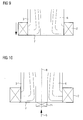
- shows an alternative solution where the rotation of the vortex core is reduced by altering the geometry of the main swirler, and
- Figure 10
- shows a counter swirler at the base of the reverse flow zone.
- In the drawings like references identify like or equivalent parts.
-
Figure 1 is a sketch of a lean premixedgas turbine combustor 1 withswirler 2, mixingchamber 3 andmain combustion chamber 4, showing major flow features. Themain combustion air 5 enters through asingle radial swirler 2 at the head of thecombustor 6. The flow then turns through a right angle into the mixingchamber 3 followed by a sudden expansion into thecombustion chamber 4. The swirl number is sufficiently high to induce a vortex breakdown reverse flow zone along theaxis 8 of the combustor. This is termed the internalreverse flow zone 9. The internalreverse flow zone 9 remains attached to the back surface of the combustor, which is theback face 7 of the burner, thereby establishing a firm aerodynamic base for flame stabilisation. In the wake of the sudden expansion, an externalreverse flow zone 11 is established. The flame is stabilised in the shear layers around the internal and externalreverse flow zones rotating vortex core 12 is indicated along theaxis 8 of thecombustor 1 and directing to the turbine. -
Figure 2 shows the sketch of a lean premixedgas turbine combustor 1 withflow generating elements 13 arranged on theback face 7 of the burner, outside but close to the region where the internalreverse flow zone 9 is anchored.Figure 2 further shows the contra-rotation fromvortex generating elements 13 reducing rotation and vorticity in thecore 12. -
Figure 3 shows a close-up view of thevortex generating elements 13 arranged on theback face 7 of the burner, theswirler 2 and the streamlines of air and fuel. -
Figures 4 to 7 show different views onto avortex generating element 13.Figure 4 represents a top view of avortex generating element 13 with an arrow indicating the direction of themain flow 5 first approaching thefront edge 20 of thetop surface 16. Afirst side surface 14 is in parallel to theflow direction 5 and may be curved to better align with the streamlines so that no vortex will be generated at thefirst edge 19 betweentop surface 16 andfirst side surface 14. Avortex 22 is generated at thesecond edge 15 between thetop surface 16 and thesecond side surface 17. -
Figure 5 represents a perspective view of avortex generating element 13 showing its tetrahedral shape. The first and second side surfaces 14,17 include a connectingedge 18 connecting first and second side faces 14,17. Thesecond edge 15 of thetop surface 16 abutting the second side surfaces 17 is configured to be essentially sharp. The connectingedge 18 forms a downstream edge of thevortex generating element 13 and thefront edge 20 of thetop surface 16 is an edge which amain flow 5 approaches first. -
Figure 6 represents a rear view of avortex generating element 13 and shows thesecond side surface 17 with avortex 22 generated at thesecond edge 15 betweentop surface 16 andsecond side surface 17. -
Figure 7 represents a side view of avortex generating element 13. Again, thesecond side surface 17 is shown. - Referring to
Figure 8 an arrangement ofvortex generating elements 13 on theback face 7 of a burner is shown. Any number ofvortex generating elements 13 can be arranged on theburner face 7 outside but close to the region where the internalreverse flow zone 9 is anchored.Figure 8 shows examples ofstreamlines 5 over theburner face 7. The first side surfaces 14 can be curved to better align with the streamlines.Vortices 22 are generated atsecond edges 15 betweentop surface 16 andsecond side surface 17. - As an alternative to the
vortex generating elements 13 the swirl in thevortex core 12 could also be reduced through modification of theswirler 2. For example, the swirler angle could be reduced along the height of theswirler 2, as theback face 7 of the burner is approached, as shown infigure 9 . - As another alternative, the
vortex core 12 could also be targeted by introducing features at the back face of theburner 7, within the internalreverse flow zone 9, such as acounter swirler 21 at the base of the internalreverse flow zone 12 as shown inFigure 10 . - The
back face 7 of the burner is shown as straight in the figures. However the application of this invention is not limited to a straight burner back face. The face could be curved, or angled, both towards the combustor or away from the combustor.
Claims (15)
- A mixing chamber (3), comprising:a wall (10),at least one vortex generating element (13) arranged on the wall (10), the at least one vortex generating element (13) having at least three surfaces (14,16,17), at least one of the surfaces forming a top surface (16) and the other surfaces forming at least first and second side surfaces (14,17), the first and second side surfaces (14,17) arranged not in parallel,the top surface (16) being in contact with the wall (10) via a front edge (20) of the top surface, the front edge (20) extending traverse to a flow direction,the top surface (16) further abutting the first and second side faces (14,17) forming first and second edges (19,15),the first side surface (14) extending in parallel to the flow direction so that the first edge (19) does not contribute to generating a vortex,and the second side surface (17) extending not in parallel to the flow direction so that the second edge (15) contributes to generating the vortex.
- The mixing chamber (3) as claimed in claim 1, wherein the first and second side faces (14,17) include a connecting edge (18) connecting first and second side faces (14,17), the connecting edge (18) preferably extending perpendicular relative to the wall (10).
- The mixing chamber (3) as claimed in claim 1 or 2, wherein the second edge (15) is configured to be essentially sharp.
- The mixing chamber (3) as claimed in claim 2, wherein the connecting edge (18) forms a downstream edge of the vortex generating element (13), and the front edge (20) of the top surface (16) is an edge which a main flow approaches first relative to the flow direction.
- The mixing chamber (3) as claimed in any of the preceding claims, the mixing chamber (3) having an tubular shape.
- The mixing chamber (3) as claimed in any of the preceding claims, wherein a plurality of vortex generating elements (13) is arranged on the wall (10) on a common radial.
- The mixing chamber (3) as claimed in any of the preceding claims, wherein at least one fuel injection opening is arranged on the vortex generating element (13).
- The mixing chamber (3) as claimed in any of the preceding claims, wherein the wall (10) is a back face (7) of a burner.
- The mixing chamber (3) as claimed in any of the preceding claims, wherein the vortex generating element (13) is arranged outside, but close to a region where a central reverse flow zone (9) is anchored during operation of the mixing chamber (3).
- The mixing chamber (3) as claimed in any of the preceding claims, wherein the vortex generating element (13) consists of a different material compared to the wall (10) to which it is attached.
- The mixing chamber (3) as claimed in claim 10, wherein the material is a sintered high temperature machining tool material.
- The mixing chamber (3) as claimed in claim 10, wherein the material is a sprayed-on ceramic.
- A combustion apparatus comprising a mixing chamber (3) as claimed in any of the preceding claims, wherein the flow direction is determined by a swirler (2) arranged upstream of the mixing chamber (3).
- The combustion apparatus as claimed in claim 13, wherein the swirler (2) comprises a plurality of vanes arranged on a first circle, and flow slots being defined between adjacent vanes and arranged tangential relative to a second circle defined by radially inner ends of the vanes.
- The combustion apparatus as claimed in claim 13 or 14, wherein the vanes are shaped as wedges.
Priority Applications (2)
| Application Number | Priority Date | Filing Date | Title |
|---|---|---|---|
| EP08007874A EP2112433A1 (en) | 2008-04-23 | 2008-04-23 | Mixing chamber |
| US12/386,834 US8424310B2 (en) | 2008-04-23 | 2009-04-23 | Mixing chamber |
Applications Claiming Priority (1)
| Application Number | Priority Date | Filing Date | Title |
|---|---|---|---|
| EP08007874A EP2112433A1 (en) | 2008-04-23 | 2008-04-23 | Mixing chamber |
Publications (1)
| Publication Number | Publication Date |
|---|---|
| EP2112433A1 true EP2112433A1 (en) | 2009-10-28 |
Family
ID=40042734
Family Applications (1)
| Application Number | Title | Priority Date | Filing Date |
|---|---|---|---|
| EP08007874A Withdrawn EP2112433A1 (en) | 2008-04-23 | 2008-04-23 | Mixing chamber |
Country Status (2)
| Country | Link |
|---|---|
| US (1) | US8424310B2 (en) |
| EP (1) | EP2112433A1 (en) |
Cited By (2)
| Publication number | Priority date | Publication date | Assignee | Title |
|---|---|---|---|---|
| EP2743588A1 (en) | 2012-12-11 | 2014-06-18 | Siemens Aktiengesellschaft | Recessed fuel injector positioning |
| US20170009994A1 (en) * | 2014-02-06 | 2017-01-12 | Siemens Aktiengesellschaft | Combustor |
Families Citing this family (2)
| Publication number | Priority date | Publication date | Assignee | Title |
|---|---|---|---|---|
| DE102012206507A1 (en) * | 2012-04-20 | 2013-10-24 | BSH Bosch und Siemens Hausgeräte GmbH | Burner for a gas-fired cooking appliance |
| CN110947537B (en) * | 2019-11-29 | 2025-04-25 | 深圳市泰达机器人有限公司 | A multi-fluid mixer and mixing test method |
Citations (11)
| Publication number | Priority date | Publication date | Assignee | Title |
|---|---|---|---|---|
| GB2228010A (en) | 1988-12-28 | 1990-08-15 | Sumitomo Rubber Ind | One-piece solid golf ball |
| EP0619456A1 (en) | 1993-04-08 | 1994-10-12 | ABB Management AG | Fuel supply system for combustion chamber |
| GB2288010A (en) * | 1994-04-02 | 1995-10-04 | Abb Management Ag | Premixing burner |
| EP0675322A2 (en) * | 1994-04-02 | 1995-10-04 | ABB Management AG | Premix burner |
| DE4417538A1 (en) * | 1994-05-19 | 1995-11-23 | Abb Management Ag | Combustion chamber with self-ignition |
| EP0718558A2 (en) * | 1994-12-24 | 1996-06-26 | ABB Management AG | Combustor |
| EP0718561A2 (en) * | 1994-12-24 | 1996-06-26 | ABB Management AG | Combustor |
| EP0733861A2 (en) * | 1995-03-24 | 1996-09-25 | ABB Management AG | Combustor for staged combustion |
| EP0745809A1 (en) * | 1995-06-02 | 1996-12-04 | ABB Management AG | Vortex generator for combustion chamber |
| WO2007096294A1 (en) | 2006-02-22 | 2007-08-30 | Siemens Aktiengesellschaft | A swirler for use in a burner of a gas turbine engine |
| WO2007131818A1 (en) | 2006-05-12 | 2007-11-22 | Siemens Aktiengesellschaft | A swirler for use in a burner of a gas turbine engine |
Family Cites Families (16)
| Publication number | Priority date | Publication date | Assignee | Title |
|---|---|---|---|---|
| US2958195A (en) * | 1959-02-25 | 1960-11-01 | Philip G Dooley | Air inlet construction |
| US3811278A (en) * | 1973-02-01 | 1974-05-21 | Gen Electric | Fuel injection apparatus |
| US4363208A (en) * | 1980-11-10 | 1982-12-14 | General Motors Corporation | Ceramic combustor mounting |
| US4619580A (en) * | 1983-09-08 | 1986-10-28 | The Boeing Company | Variable camber vane and method therefor |
| US5165241A (en) * | 1991-02-22 | 1992-11-24 | General Electric Company | Air fuel mixer for gas turbine combustor |
| CH687831A5 (en) * | 1993-04-08 | 1997-02-28 | Asea Brown Boveri | Premix burner. |
| US5351477A (en) * | 1993-12-21 | 1994-10-04 | General Electric Company | Dual fuel mixer for gas turbine combustor |
| US5636510A (en) * | 1994-05-25 | 1997-06-10 | Westinghouse Electric Corporation | Gas turbine topping combustor |
| US5613363A (en) * | 1994-09-26 | 1997-03-25 | General Electric Company | Air fuel mixer for gas turbine combustor |
| GB2332509B (en) * | 1997-12-19 | 2002-06-19 | Europ Gas Turbines Ltd | Fuel/air mixing arrangement for combustion apparatus |
| GB2333832A (en) * | 1998-01-31 | 1999-08-04 | Europ Gas Turbines Ltd | Multi-fuel gas turbine engine combustor |
| GB2337102A (en) * | 1998-05-09 | 1999-11-10 | Europ Gas Turbines Ltd | Gas-turbine engine combustor |
| US6834505B2 (en) * | 2002-10-07 | 2004-12-28 | General Electric Company | Hybrid swirler |
| US6993916B2 (en) * | 2004-06-08 | 2006-02-07 | General Electric Company | Burner tube and method for mixing air and gas in a gas turbine engine |
| US7565803B2 (en) * | 2005-07-25 | 2009-07-28 | General Electric Company | Swirler arrangement for mixer assembly of a gas turbine engine combustor having shaped passages |
| NZ541586A (en) | 2005-07-29 | 2008-03-28 | Kevin Allan Saunders | Fire retardant elevated floor structure for a building |
-
2008
- 2008-04-23 EP EP08007874A patent/EP2112433A1/en not_active Withdrawn
-
2009
- 2009-04-23 US US12/386,834 patent/US8424310B2/en not_active Expired - Fee Related
Patent Citations (11)
| Publication number | Priority date | Publication date | Assignee | Title |
|---|---|---|---|---|
| GB2228010A (en) | 1988-12-28 | 1990-08-15 | Sumitomo Rubber Ind | One-piece solid golf ball |
| EP0619456A1 (en) | 1993-04-08 | 1994-10-12 | ABB Management AG | Fuel supply system for combustion chamber |
| GB2288010A (en) * | 1994-04-02 | 1995-10-04 | Abb Management Ag | Premixing burner |
| EP0675322A2 (en) * | 1994-04-02 | 1995-10-04 | ABB Management AG | Premix burner |
| DE4417538A1 (en) * | 1994-05-19 | 1995-11-23 | Abb Management Ag | Combustion chamber with self-ignition |
| EP0718558A2 (en) * | 1994-12-24 | 1996-06-26 | ABB Management AG | Combustor |
| EP0718561A2 (en) * | 1994-12-24 | 1996-06-26 | ABB Management AG | Combustor |
| EP0733861A2 (en) * | 1995-03-24 | 1996-09-25 | ABB Management AG | Combustor for staged combustion |
| EP0745809A1 (en) * | 1995-06-02 | 1996-12-04 | ABB Management AG | Vortex generator for combustion chamber |
| WO2007096294A1 (en) | 2006-02-22 | 2007-08-30 | Siemens Aktiengesellschaft | A swirler for use in a burner of a gas turbine engine |
| WO2007131818A1 (en) | 2006-05-12 | 2007-11-22 | Siemens Aktiengesellschaft | A swirler for use in a burner of a gas turbine engine |
Cited By (5)
| Publication number | Priority date | Publication date | Assignee | Title |
|---|---|---|---|---|
| EP2743588A1 (en) | 2012-12-11 | 2014-06-18 | Siemens Aktiengesellschaft | Recessed fuel injector positioning |
| WO2014090493A1 (en) | 2012-12-11 | 2014-06-19 | Siemens Aktiengesellschaft | Recessed fuel injector positioning |
| US9816707B2 (en) | 2012-12-11 | 2017-11-14 | Siemens Aktiengesellschaft | Recessed fuel injector positioning |
| US20170009994A1 (en) * | 2014-02-06 | 2017-01-12 | Siemens Aktiengesellschaft | Combustor |
| US10240795B2 (en) * | 2014-02-06 | 2019-03-26 | Siemens Aktiengesellschaft | Pilot burner having burner face with radially offset recess |
Also Published As
| Publication number | Publication date |
|---|---|
| US20090266077A1 (en) | 2009-10-29 |
| US8424310B2 (en) | 2013-04-23 |
Similar Documents
| Publication | Publication Date | Title |
|---|---|---|
| EP2685164B1 (en) | Axial swirler for a gas turbine burner | |
| JP5871881B2 (en) | Burner for can-type combustor | |
| CN101713549B (en) | System and method for air-fuel mixing in gas turbines | |
| US8789375B2 (en) | Gas turbine combustor having counterflow injection mechanism and method of use | |
| EP3147571B1 (en) | A fuel injector for a gas turbine engine combustion chamber | |
| CN101377305A (en) | Premixer with radial staged flow channels and method for mixing air and gas | |
| JP2007285572A (en) | Premixed combustion burner for gas turbine | |
| KR20140058376A (en) | Axial swirler | |
| CN102865598A (en) | Premixer fuel nozzle for gas turbine engine | |
| KR101781722B1 (en) | Combustion burner, combustor and gas burner | |
| JP6084138B2 (en) | Premix burner | |
| JP2013213659A (en) | Swirler for combustion chamber | |
| CN110793061A (en) | Dilution structures for gas turbine engine combustors | |
| JP2019516058A (en) | A swirler for mixing fuel with air in a combustion engine | |
| EP2730846A2 (en) | Fuel injector | |
| US8424310B2 (en) | Mixing chamber | |
| EP3403028B1 (en) | Combustor for a gas turbine | |
| US20180299129A1 (en) | Combustor for a gas turbine | |
| WO2019230165A1 (en) | Liquid fuel injector | |
| JP6824165B2 (en) | Liner with a given contour of the flame sheet combustor | |
| JP6934350B2 (en) | gas turbine | |
| JP6870966B2 (en) | Combustor nozzle and gas turbine | |
| EP4641089A1 (en) | Fuel injector for a turbine engine | |
| EP3184898A1 (en) | Combustor for a gas turbine |
Legal Events
| Date | Code | Title | Description |
|---|---|---|---|
| PUAI | Public reference made under article 153(3) epc to a published international application that has entered the european phase |
Free format text: ORIGINAL CODE: 0009012 |
|
| AK | Designated contracting states |
Kind code of ref document: A1 Designated state(s): AT BE BG CH CY CZ DE DK EE ES FI FR GB GR HR HU IE IS IT LI LT LU LV MC MT NL NO PL PT RO SE SI SK TR |
|
| AX | Request for extension of the european patent |
Extension state: AL BA MK RS |
|
| 17P | Request for examination filed |
Effective date: 20100428 |
|
| AKX | Designation fees paid |
Designated state(s): DE FR GB |
|
| 17Q | First examination report despatched |
Effective date: 20100611 |
|
| RAP1 | Party data changed (applicant data changed or rights of an application transferred) |
Owner name: SIEMENS AKTIENGESELLSCHAFT |
|
| STAA | Information on the status of an ep patent application or granted ep patent |
Free format text: STATUS: THE APPLICATION IS DEEMED TO BE WITHDRAWN |
|
| 18D | Application deemed to be withdrawn |
Effective date: 20141031 |