EP2112432A1 - Explosion-proof lighting device - Google Patents
Explosion-proof lighting device Download PDFInfo
- Publication number
- EP2112432A1 EP2112432A1 EP09005505A EP09005505A EP2112432A1 EP 2112432 A1 EP2112432 A1 EP 2112432A1 EP 09005505 A EP09005505 A EP 09005505A EP 09005505 A EP09005505 A EP 09005505A EP 2112432 A1 EP2112432 A1 EP 2112432A1
- Authority
- EP
- European Patent Office
- Prior art keywords
- explosion
- lighting device
- light source
- proof lighting
- electrically insulating
- Prior art date
- Legal status (The legal status is an assumption and is not a legal conclusion. Google has not performed a legal analysis and makes no representation as to the accuracy of the status listed.)
- Granted
Links
- 239000000206 moulding compound Substances 0.000 claims abstract description 24
- 229920005989 resin Polymers 0.000 claims description 15
- 239000011347 resin Substances 0.000 claims description 15
- 239000004593 Epoxy Substances 0.000 claims description 4
- 239000004952 Polyamide Substances 0.000 claims description 4
- 239000004698 Polyethylene Substances 0.000 claims description 4
- 239000004793 Polystyrene Substances 0.000 claims description 4
- 150000001875 compounds Chemical class 0.000 claims description 4
- 239000000463 material Substances 0.000 claims description 4
- 229920002647 polyamide Polymers 0.000 claims description 4
- 229920000647 polyepoxide Polymers 0.000 claims description 4
- 229920000728 polyester Polymers 0.000 claims description 4
- -1 polyethylene Polymers 0.000 claims description 4
- 229920000573 polyethylene Polymers 0.000 claims description 4
- 229920002223 polystyrene Polymers 0.000 claims description 4
- 229920002635 polyurethane Polymers 0.000 claims description 4
- 239000004814 polyurethane Substances 0.000 claims description 4
- 230000001419 dependent effect Effects 0.000 claims 1
- 238000004880 explosion Methods 0.000 description 12
- 239000002360 explosive Substances 0.000 description 4
- 238000005538 encapsulation Methods 0.000 description 3
- 239000007787 solid Substances 0.000 description 3
- 239000000126 substance Substances 0.000 description 3
- 238000002485 combustion reaction Methods 0.000 description 2
- 238000010276 construction Methods 0.000 description 2
- 239000000428 dust Substances 0.000 description 2
- 239000007789 gas Substances 0.000 description 2
- 238000000034 method Methods 0.000 description 2
- 239000000203 mixture Substances 0.000 description 2
- 230000006978 adaptation Effects 0.000 description 1
- 230000007547 defect Effects 0.000 description 1
- 230000002950 deficient Effects 0.000 description 1
- 238000005553 drilling Methods 0.000 description 1
- 238000001035 drying Methods 0.000 description 1
- 238000010616 electrical installation Methods 0.000 description 1
- 230000009970 fire resistant effect Effects 0.000 description 1
- 239000007788 liquid Substances 0.000 description 1
- 238000004519 manufacturing process Methods 0.000 description 1
- 238000013021 overheating Methods 0.000 description 1
- 239000000725 suspension Substances 0.000 description 1
Images


Classifications
-
- F—MECHANICAL ENGINEERING; LIGHTING; HEATING; WEAPONS; BLASTING
- F21—LIGHTING
- F21V—FUNCTIONAL FEATURES OR DETAILS OF LIGHTING DEVICES OR SYSTEMS THEREOF; STRUCTURAL COMBINATIONS OF LIGHTING DEVICES WITH OTHER ARTICLES, NOT OTHERWISE PROVIDED FOR
- F21V25/00—Safety devices structurally associated with lighting devices
- F21V25/12—Flameproof or explosion-proof arrangements
-
- F—MECHANICAL ENGINEERING; LIGHTING; HEATING; WEAPONS; BLASTING
- F21—LIGHTING
- F21V—FUNCTIONAL FEATURES OR DETAILS OF LIGHTING DEVICES OR SYSTEMS THEREOF; STRUCTURAL COMBINATIONS OF LIGHTING DEVICES WITH OTHER ARTICLES, NOT OTHERWISE PROVIDED FOR
- F21V31/00—Gas-tight or water-tight arrangements
- F21V31/04—Provision of filling media
-
- F—MECHANICAL ENGINEERING; LIGHTING; HEATING; WEAPONS; BLASTING
- F21—LIGHTING
- F21Y—INDEXING SCHEME ASSOCIATED WITH SUBCLASSES F21K, F21L, F21S and F21V, RELATING TO THE FORM OR THE KIND OF THE LIGHT SOURCES OR OF THE COLOUR OF THE LIGHT EMITTED
- F21Y2103/00—Elongate light sources, e.g. fluorescent tubes
Definitions
- the present invention relates to an explosion-proof lighting device comprising a light source and a luminaire provided with a supply source for providing the light source with a supply voltage.
- Explosion-proof lighting devices are widely used in industrial applications, especially in locations where fire safety is of major importance such as oil refineries, drilling platforms, etc. Electrical installations in such applications should often comply with the ATEX guidelines issued by the European Union.
- the ATEX guideline applies to all locations where there is a risk of explosions; it has been in force since 1996.
- the guideline relates not only to the risk of gas explosions, but also, for example, to the risk of dust explosions, and applies to apparatuses and other electrical systems.
- the object of these guidelines is to safeguard the health and safety of personnel working in such locations.
- ATEX is short for the French expression "shoulder expression "shoulder explosive” and refers to explosive atmospheres, the definition of which is: a mixture of combustible substances in the form of gases , vapours, mists and dust under atmospheric conditions in which a combustion process after ignition will spread over the entire as yet not combusted mixture.
- Ex and EEx classes are classified into Ex and EEx classes under the ATEX guidelines.
- Ex classes that can be distinguished there is, for example, Ex e, which is a classification for equipment that is designed such that its components cannot cause any sparks or high temperatures in normal use and that it is insulated from its surroundings.
- the equipment should in addition be impact-resistant so as to be able to withstand as much as possible any external forces released in the case of an emergency.
- the explosion safety techniques classified under Ex m serve to ensure that potentially flammable components are encapsulated or encased in a moulding compound.
- the flammable atmosphere is thus separated from the flammable components while at the same time the surface temperature of the encapsulated components can be kept under control.
- Industrial lighting devices usually comprise an (explosion-proof) luminaire provided with a light source, which luminaire is provided with a supply source for providing the light source with a supply voltage.
- the light source in the luminaire can be replaced when it becomes defective.
- a disadvantage of a lighting device according to the prior art is that the luminaire itself is indeed explosion-proof, but the (replaceable) light source still present an explosion risk.
- this object is achieved in that it offers an explosion-proof lighting device comprising a light source and a luminaire provided with a supply source for providing the light source with a supply voltage, wherein the light source is provided with connection means by which the light source is non-detachably connected to the supply source for receiving the supply voltage, said connection means being encapsulated in an electrically insulating moulding compound.
- the explosion-proof lighting device in its entirety, including the light source now complies with the Ex m classification of the ATEX guideline owing to the fact that the connection means of the light source itself are encapsulated in an electrically insulating moulding compound.
- the simple encapsulation of the connection means of the light source in an electrically insulating moulding compound enables the luminaire to fall within the Ex m category in a simple manner, possibly without any substantial adaptations to the basic construction of the luminaire, if so desired.
- the electrically insulating compound comprises a resin.
- a resin instead of a gel in preferred especially in maintenance-free applications, where the explosion-proof lighting device is constructed such that its light source is not accessible from the outside, or cannot be replaced.
- the resin will dry up so as to form a solid encapsulating substance that separates the connection means from the atmosphere.
- the electrically insulating moulding compound may alternatively comprise a gel.
- the advantage of the use of a gel is that a gel does not constitute a solid substance but a liquid of usually high viscosity. A gel is usually held in place under the influence of its own surface tension.
- the light source is detachably connected to the luminaire.
- a disadvantage is, however, that a gel is not impact-resistant and accordingly does not fully comply with the explosion safety requirements. This embodiment accordingly cannot be regarded as particularly suitable for achieving the Ex m classification.
- the encapsulation of the contact points in a gel in itself contributes to the fire safety of the luminaire. The contact points are in fact effectively screened off from the surroundings, so that sparking and the resulting fire risk are eliminated, while at the same time the gel provides an excellent thermal conduction.
- the electrically insulating moulding compound may comprise a material chosen from a group comprising polyepoxide or epoxy, polyurethane, polyethylene, polyester, polystyrene and polyamide.
- the explosion-proof lighting device comprises a light source housing for accommodating the light source.
- the electrically insulating moulding compound may then be present inside the light source housing.
- the explosion-proof lighting device comprises a control circuit for controlling and adjusting the supply voltage that is fed to the light source.
- This control circuit may also be encapsulated in a further electrically insulating moulding compound.
- This further electrically insulating moulding compound may again comprise a gel or a resin. If a gel is used, the electronics of the control circuit are still accessible at a later stage, so that the lighting device can be repaired in the case of a defect.
- a maintenance-free luminaire is opted for, however, in which the light source itself may be replaceable, for example through the use of a gel as the moulding compound, then it may be considered to choose a resin for the further electrically insulating moulding compound, which will become hard after drying up so as to form a solid encapsulation.
- the further electrically insulating moulding compound may comprise a material chosen from a group comprising polyepoxide or epoxy, polyurethane, polyethylene, polyester, polystyrene, and polyamide.
- the light source and the control circuit of the lighting device are located such that they are thermally separated from one another so as to counteract mutual temperature influences.
- This may be achieved, for example, in that the light source housing mentioned above is physically separated from the control circuit.
- the control circuit may be accommodated in a separate dedicated circuit housing.
- Said circuit housing may contain the further electrically insulating moulding compound and may be, for example, completely filled thereby. This not only provides a satisfactory closing-off of any ignition sources with respect to the surroundings, but it is also capable of achieving that heat originating from said ignition sources can be effectively removed.
- the circuit housing and the light source housing mentioned above may be integrated into a single device housing while nevertheless being located separately from one another.
- the lighting device may be provided with a temperature sensor which is operatively connected to the control circuit, such that the control circuit is arranged for controlling the supply voltage in dependence on a signal from the temperature sensor.
- a temperature sensor which is operatively connected to the control circuit, such that the control circuit is arranged for controlling the supply voltage in dependence on a signal from the temperature sensor.
- Figure 1 shows a lighting device 1 according to the invention, comprising two light sources connected to a luminaire 4.
- the luminaire 4 is formed by a housing 5 consisting of a light source housing or hood 6 and a housing part 8 that adjoins the hood 6.
- connection parts 11 which are constructed so as to cooperate with contact points (not visible in figure 1 ) of the light sources 3 for providing an electrical connection between the light sources 3 and the parts of the luminaire operational in energizing the light sources 3.
- a control circuit (not visible) for controlling and adjusting the supply voltage fed to the light sources 3 is present in the housing part 8 of the lighting device.
- the control circuit of the luminaire 4 is supplied with current from the public mains.
- the mains current can be supplied to the luminaire 4 by means of cables passed through inlets 9.
- Connection terminals (not visible in figure 1 ) are situated in the interior of the housing 5, in the housing part 12 adjacent the inlets 9, for providing the mains voltage to the control circuit.
- the connection parts 11 are filled with an electrically insulating, thermally conductive resin after the connection points of the light sources have been connected, such that an explosion-proof connection complying with the Ex m standard is obtained.
- the connection parts 11 are shaped for this purpose such that, after their connection to the light source 3, there is still sufficient space that can be filled up with the electrically insulating resin.
- Figure 2 is a bottom view of the lighting device shown in figure 1 .
- the bottom view shows the lighting device 1 provided with light sources 3, fastening parts 10, and connection parts 11 for the light sources 3.
- the housing part 12 and the inlets 9 for the mains voltage as well as the light source housing 6 are visible in figure 2.
- Figure 3 which will be discussed below, is a cross-sectional view taken on the line A-A.
- Figure 3 shows the luminaire and the light source of figures 1 and 2 in cross-section.
- the cross-sectional view shows the housing 5 comprising the housing part 8, the housing part 12, and the light source housing 6. Furthermore, a cross-section is visible of the fastening means 10 which are provided with connection parts 11.
- the cross-section of figure 3 also shows the light source 3.
- a control circuit housing in which a control circuit 15 is present is accommodated in the housing part 8 of the housing 5.
- the control circuit 15 is fully encapsulated in an electrically insulating gel or resin which screens off the ignition-sensitive parts of the control circuit from the surroundings in an explosion-proof manner.
- the control circuit is supplied from the public mains by means of power cords, so that a connection can be established via inlet 9 to connection terminals of the luminaire for supplying the mains voltage to the luminaire.
- This mains voltage is passed on to the control circuit 15 via mains voltage connections present in a space 17 of the housing.
- Both the space 17 and the housing part 12 are preferably filled up with an electrically insulating moulding compound, such as a resin or a gel, for separating the ignition-sensitive lines from the (explosive) atmosphere in accordance with the Ex m standard.
- the luminaire 4 further comprises suspension elements 18 for fastening the luminaire to a ceiling.
- the elements 18 are mounted to the housing 5 of the luminaire 4 in such a manner that they can be steplessly shifted so as to fit the location where these elements 18 are to be fastened in the local situation.
- the elements are suitably shaped for this purpose and cooperate with the housing 5 (not shown), said housing forming a rail over which the elements 18 can glide.
- Other solutions for adapting the locations of the elements 18 to the local situation will readily suggest themselves to those skilled in the art.
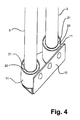
- Figure 4 shows on an enlarged scale a fastening part 10 provided with connection parts 11 for connecting the light sources 3 to the luminaire. It is apparent from figure 4 that the connection parts 11 are cup-shaped and that a lampholder unit 20 is present inside the cup shape of each connection part 11 for connecting contact points 21 of the light source 3.
- the lampholder units 20 are slightly smaller than the diameter of the cup of the connection part 11, so that the lampholder units 20 and the contact points 21 can be fully enveloped by the electrically insulating moulding compound in the form of a resin.
- a light source is provided in this manner which complies with the explosion safety standard Ex m in accordance with the ATEX guideline.
- the luminaire no longer meets the requirements as to explosion safety according to Ex m, but a fire-resistant solution is nevertheless obtained that is still quite suitable for application in an industrial environment.
Landscapes
- Engineering & Computer Science (AREA)
- General Engineering & Computer Science (AREA)
- Arrangement Of Elements, Cooling, Sealing, Or The Like Of Lighting Devices (AREA)
- Non-Portable Lighting Devices Or Systems Thereof (AREA)
Abstract
Description
- The present invention relates to an explosion-proof lighting device comprising a light source and a luminaire provided with a supply source for providing the light source with a supply voltage.
- Explosion-proof lighting devices are widely used in industrial applications, especially in locations where fire safety is of major importance such as oil refineries, drilling platforms, etc. Electrical installations in such applications should often comply with the ATEX guidelines issued by the European Union. The ATEX guideline applies to all locations where there is a risk of explosions; it has been in force since 1996. The guideline relates not only to the risk of gas explosions, but also, for example, to the risk of dust explosions, and applies to apparatuses and other electrical systems. The object of these guidelines is to safeguard the health and safety of personnel working in such locations. ATEX is short for the French expression "atmosphère explosive" and refers to explosive atmospheres, the definition of which is: a mixture of combustible substances in the form of gases , vapours, mists and dust under atmospheric conditions in which a combustion process after ignition will spread over the entire as yet not combusted mixture.
- Explosion protection techniques are classified into Ex and EEx classes under the ATEX guidelines. Among the Ex classes that can be distinguished there is, for example, Ex e, which is a classification for equipment that is designed such that its components cannot cause any sparks or high temperatures in normal use and that it is insulated from its surroundings. The equipment should in addition be impact-resistant so as to be able to withstand as much as possible any external forces released in the case of an emergency.
- Another explosion protection is classified sub Ex d, wherein a device is provided with a pressure-resistant envelope such that components that cause sparks or high temperatures in normal use and that may come into contact with the explosive atmosphere inside the device cannot cause combustion or explosion outside the pressure-resistant envelope.
- The explosion safety techniques classified under Ex m serve to ensure that potentially flammable components are encapsulated or encased in a moulding compound. The flammable atmosphere is thus separated from the flammable components while at the same time the surface temperature of the encapsulated components can be kept under control.
- Industrial lighting devices usually comprise an (explosion-proof) luminaire provided with a light source, which luminaire is provided with a supply source for providing the light source with a supply voltage. The light source in the luminaire can be replaced when it becomes defective. A disadvantage of a lighting device according to the prior art is that the luminaire itself is indeed explosion-proof, but the (replaceable) light source still present an explosion risk.
- In order to make the lighting device explosion-proof in spite of this, it may be considered to place the luminaire in an explosion-proof housing (Ex d or Ex p), but this will make the lighting device expensive.
- It is an object of the present invention to counteract the problems inherent in the prior art and to provide an explosion-proof lighting device that is of a simple construction.
- According to the invention, this object is achieved in that it offers an explosion-proof lighting device comprising a light source and a luminaire provided with a supply source for providing the light source with a supply voltage, wherein the light source is provided with connection means by which the light source is non-detachably connected to the supply source for receiving the supply voltage, said connection means being encapsulated in an electrically insulating moulding compound.
- The explosion-proof lighting device in its entirety, including the light source, now complies with the Ex m classification of the ATEX guideline owing to the fact that the connection means of the light source itself are encapsulated in an electrically insulating moulding compound. The simple encapsulation of the connection means of the light source in an electrically insulating moulding compound enables the luminaire to fall within the Ex m category in a simple manner, possibly without any substantial adaptations to the basic construction of the luminaire, if so desired.
- In an embodiment of the present invention, the electrically insulating compound comprises a resin. The use of a resin instead of a gel in preferred especially in maintenance-free applications, where the explosion-proof lighting device is constructed such that its light source is not accessible from the outside, or cannot be replaced. Following the manufacturing process of the lighting device in which the resin is moulded for encapsulating the connection means, the resin will dry up so as to form a solid encapsulating substance that separates the connection means from the atmosphere.
- The electrically insulating moulding compound may alternatively comprise a gel. The advantage of the use of a gel is that a gel does not constitute a solid substance but a liquid of usually high viscosity. A gel is usually held in place under the influence of its own surface tension. When a gel is used for encapsulating the connection means, the light source is detachably connected to the luminaire. A disadvantage is, however, that a gel is not impact-resistant and accordingly does not fully comply with the explosion safety requirements. This embodiment accordingly cannot be regarded as particularly suitable for achieving the Ex m classification. On the other hand, the encapsulation of the contact points in a gel in itself contributes to the fire safety of the luminaire. The contact points are in fact effectively screened off from the surroundings, so that sparking and the resulting fire risk are eliminated, while at the same time the gel provides an excellent thermal conduction.
- According to an embodiment of the invention, the electrically insulating moulding compound may comprise a material chosen from a group comprising polyepoxide or epoxy, polyurethane, polyethylene, polyester, polystyrene and polyamide.
- In another embodiment, the explosion-proof lighting device comprises a light source housing for accommodating the light source. The electrically insulating moulding compound may then be present inside the light source housing.
- According to another embodiment of the invention, the explosion-proof lighting device comprises a control circuit for controlling and adjusting the supply voltage that is fed to the light source. This control circuit may also be encapsulated in a further electrically insulating moulding compound. This further electrically insulating moulding compound may again comprise a gel or a resin. If a gel is used, the electronics of the control circuit are still accessible at a later stage, so that the lighting device can be repaired in the case of a defect. If a maintenance-free luminaire is opted for, however, in which the light source itself may be replaceable, for example through the use of a gel as the moulding compound, then it may be considered to choose a resin for the further electrically insulating moulding compound, which will become hard after drying up so as to form a solid encapsulation.
- In an embodiment of this version, the further electrically insulating moulding compound may comprise a material chosen from a group comprising polyepoxide or epoxy, polyurethane, polyethylene, polyester, polystyrene, and polyamide.
- In another preferred embodiment, the light source and the control circuit of the lighting device are located such that they are thermally separated from one another so as to counteract mutual temperature influences. This may be achieved, for example, in that the light source housing mentioned above is physically separated from the control circuit. The control circuit may be accommodated in a separate dedicated circuit housing. Said circuit housing may contain the further electrically insulating moulding compound and may be, for example, completely filled thereby. This not only provides a satisfactory closing-off of any ignition sources with respect to the surroundings, but it is also capable of achieving that heat originating from said ignition sources can be effectively removed. The circuit housing and the light source housing mentioned above may be integrated into a single device housing while nevertheless being located separately from one another.
- For the purpose of controlling the temperature gradient in the lighting device, the lighting device may be provided with a temperature sensor which is operatively connected to the control circuit, such that the control circuit is arranged for controlling the supply voltage in dependence on a signal from the temperature sensor. This not only provides an additional protection against overheating and eliminates a potential explosion risk, but it may also achieve that the operating temperature of the lamp is influenced by the supply voltage to the extent that a long operational life of the light source can be obtained. This is especially advantageous in maintenance-free lighting devices in which the light source is non-detachably coupled to the luminaire, for example through the use of a fixed resin as described above.
- The invention will be explained in more detail below with reference to specific embodiments thereof, which are not to be regarded as implying any limitation, and with reference to the appended drawings, in which:
-
Figure 1 is a three-dimensional view of an explosion-proof lighting device according to the present invention; -
Figure 2 is a bottom view of the lighting device shown infigure 1 ; -
Figure 3 is a cross-sectional view of the lighting device shown infigure 1 ; and -
Figure 4 presents an enlarged view of the connection means of the light sources of the of the lighting device shown in thefigures 1 to 3 . -
Figure 1 shows a lighting device 1 according to the invention, comprising two light sources connected to aluminaire 4. Theluminaire 4 is formed by ahousing 5 consisting of a light source housing orhood 6 and ahousing part 8 that adjoins thehood 6. - At both ends of the
hood 6 there is a fasteningpart 10 for fastening twolight sources 3. Thefastening parts 10 are provided withconnection parts 11 which are constructed so as to cooperate with contact points (not visible infigure 1 ) of thelight sources 3 for providing an electrical connection between thelight sources 3 and the parts of the luminaire operational in energizing thelight sources 3. A control circuit (not visible) for controlling and adjusting the supply voltage fed to thelight sources 3 is present in thehousing part 8 of the lighting device. - The control circuit of the
luminaire 4 is supplied with current from the public mains. The mains current can be supplied to theluminaire 4 by means of cables passed throughinlets 9. Connection terminals (not visible infigure 1 ) are situated in the interior of thehousing 5, in thehousing part 12 adjacent theinlets 9, for providing the mains voltage to the control circuit. According to the invention, theconnection parts 11 are filled with an electrically insulating, thermally conductive resin after the connection points of the light sources have been connected, such that an explosion-proof connection complying with the Ex m standard is obtained. Theconnection parts 11 are shaped for this purpose such that, after their connection to thelight source 3, there is still sufficient space that can be filled up with the electrically insulating resin. -
Figure 2 is a bottom view of the lighting device shown infigure 1 . The bottom view shows the lighting device 1 provided withlight sources 3,fastening parts 10, andconnection parts 11 for thelight sources 3. Furthermore, thehousing part 12 and theinlets 9 for the mains voltage as well as thelight source housing 6 are visible infigure 2. Figure 3 , which will be discussed below, is a cross-sectional view taken on the line A-A. -
Figure 3 shows the luminaire and the light source offigures 1 and2 in cross-section. The cross-sectional view shows thehousing 5 comprising thehousing part 8, thehousing part 12, and thelight source housing 6. Furthermore, a cross-section is visible of the fastening means 10 which are provided withconnection parts 11. The cross-section offigure 3 also shows thelight source 3. - A control circuit housing in which a
control circuit 15 is present is accommodated in thehousing part 8 of thehousing 5. Thecontrol circuit 15 is fully encapsulated in an electrically insulating gel or resin which screens off the ignition-sensitive parts of the control circuit from the surroundings in an explosion-proof manner. The control circuit is supplied from the public mains by means of power cords, so that a connection can be established viainlet 9 to connection terminals of the luminaire for supplying the mains voltage to the luminaire. This mains voltage is passed on to thecontrol circuit 15 via mains voltage connections present in aspace 17 of the housing. Both thespace 17 and thehousing part 12 are preferably filled up with an electrically insulating moulding compound, such as a resin or a gel, for separating the ignition-sensitive lines from the (explosive) atmosphere in accordance with the Ex m standard. - The
luminaire 4 further comprisessuspension elements 18 for fastening the luminaire to a ceiling. Theelements 18 are mounted to thehousing 5 of theluminaire 4 in such a manner that they can be steplessly shifted so as to fit the location where theseelements 18 are to be fastened in the local situation. The elements are suitably shaped for this purpose and cooperate with the housing 5 (not shown), said housing forming a rail over which theelements 18 can glide. Other solutions for adapting the locations of theelements 18 to the local situation will readily suggest themselves to those skilled in the art. -
Figure 4 shows on an enlarged scale afastening part 10 provided withconnection parts 11 for connecting thelight sources 3 to the luminaire. It is apparent fromfigure 4 that theconnection parts 11 are cup-shaped and that alampholder unit 20 is present inside the cup shape of eachconnection part 11 for connecting contact points 21 of thelight source 3. Thelampholder units 20 are slightly smaller than the diameter of the cup of theconnection part 11, so that thelampholder units 20 and the contact points 21 can be fully enveloped by the electrically insulating moulding compound in the form of a resin. A light source is provided in this manner which complies with the explosion safety standard Ex m in accordance with the ATEX guideline. If a gel is used for the moulding compound that encloses the contact points 21 instead of a resin, the luminaire no longer meets the requirements as to explosion safety according to Ex m, but a fire-resistant solution is nevertheless obtained that is still quite suitable for application in an industrial environment. - Those skilled in the art will understand that the ideas and the operational principle as described above may be implemented in manners different from what has been specifically indicated in the figures and description. The scope of the invention is accordingly limited only by the ensuing claims.
Claims (16)
- An explosion-proof lighting device comprising a light source and a luminaire provided with a supply source for providing the light source with a supply voltage, wherein the light source is provided with connection means by which the light source is non-detachably connected to the supply source for receiving the supply voltage, said connection means being encapsulated in an electrically insulating moulding compound.
- An explosion-proof lighting device according to claim 1, wherein the electrically insulating compound comprises a gel.
- An explosion-proof lighting device according to any one of the preceding claims, wherein the electrically insulating compound comprises a resin.
- An explosion-proof lighting device according to any one of the preceding claims, wherein the electrically insulating moulding compound comprises a material chosen from a group comprising polyepoxide or epoxy, polyurethane, polyethylene, polyester, polystyrene, and polyamide.
- An explosion-proof lighting device according to any one of the preceding claims, further comprising a light source housing for accommodating the light source.
- An explosion-proof lighting device according to claim 5, wherein the electrically insulating moulding compound is present inside the light source housing.
- An explosion-proof lighting device according to any one of the preceding claims, further comprising a control circuit for controlling the supply voltage fed to the light source.
- An explosion-proof lighting device according to claim 7, wherein the control circuit is encapsulated in a further electrically insulating moulding compound.
- An explosion-proof lighting device according to claim 8, wherein the further electrically insulating compound comprises a gel or a resin.
- An explosion-proof lighting device according to any one of claims 8 and 9, wherein the further electrically insulating moulding compound comprises a material chosen from a group comprising polyepoxide or epoxy, polyurethane, polyethylene, polyester, polystyrene, and polyamide.
- An explosion-proof lighting device according to at least one of claims 7 to 10, wherein the control circuit and the light source are located such that they are thermally separated from one another so as to counteract mutual temperature influences.
- An explosion-proof lighting device according to one of claims 7 to 11, further comprising a circuit housing for accommodating the control circuit.
- An explosion-proof lighting device according to claim 12 and at least one of claims 8 to 11, wherein the further electrically insulating moulding compound is present inside the circuit housing.
- An explosion-proof lighting device according to claim 13, wherein the entire circuit housing is filled up with the further electrically insulating moulding compound.
- An explosion-proof lighting device according to one of the preceding claims insofar as dependent on at least one of claims 5 and 6 and on at least one of claims 12 to 14, wherein the circuit housing and the light source housing are integrated into a single device housing.
- An explosion-proof lighting device according to any one of claims 7 to 15, further comprising a temperature sensor which is operatively connected to the control circuit, such that the control circuit is arranged for controlling the supply voltage in dependence on a signal from said temperature sensor.
Applications Claiming Priority (1)
| Application Number | Priority Date | Filing Date | Title |
|---|---|---|---|
| NL1035324A NL1035324C2 (en) | 2008-04-22 | 2008-04-22 | Explosion proof lighting device. |
Publications (2)
| Publication Number | Publication Date |
|---|---|
| EP2112432A1 true EP2112432A1 (en) | 2009-10-28 |
| EP2112432B1 EP2112432B1 (en) | 2014-11-26 |
Family
ID=39869959
Family Applications (1)
| Application Number | Title | Priority Date | Filing Date |
|---|---|---|---|
| EP09005505.4A Not-in-force EP2112432B1 (en) | 2008-04-22 | 2009-04-17 | Explosion-proof lighting device |
Country Status (2)
| Country | Link |
|---|---|
| EP (1) | EP2112432B1 (en) |
| NL (1) | NL1035324C2 (en) |
Cited By (1)
| Publication number | Priority date | Publication date | Assignee | Title |
|---|---|---|---|---|
| US12016141B2 (en) * | 2016-12-02 | 2024-06-18 | Eaton Intelligent Power Limited | Electronic component and method for cooling |
Citations (7)
| Publication number | Priority date | Publication date | Assignee | Title |
|---|---|---|---|---|
| US4662692A (en) * | 1985-05-02 | 1987-05-05 | Raychem Corp. | Sealing member |
| DE9005059U1 (en) * | 1989-05-22 | 1990-08-23 | Frankauer, Manfred, 4350 Recklinghausen | Single-ended fluorescent tube |
| DE9010092U1 (en) * | 1990-07-03 | 1990-09-27 | M. Frankauer oHG, 4350 Recklinghausen | Fluorescent tube |
| DE4336849C1 (en) * | 1993-10-28 | 1995-01-05 | Rose Walter Gmbh & Co Kg | Method for sealing cable entries using a sealing gel |
| US5801490A (en) * | 1996-10-29 | 1998-09-01 | Catalina Lighting, Inc. | Fire-safe halogen torchiere lamp |
| EP1156272A2 (en) | 2000-05-19 | 2001-11-21 | R. Stahl Schaltgeräte GmbH | Light source |
| US20060034056A1 (en) * | 2004-08-11 | 2006-02-16 | Shigeharu Oka | Electronic apparatus and lighting device |
-
2008
- 2008-04-22 NL NL1035324A patent/NL1035324C2/en not_active IP Right Cessation
-
2009
- 2009-04-17 EP EP09005505.4A patent/EP2112432B1/en not_active Not-in-force
Patent Citations (7)
| Publication number | Priority date | Publication date | Assignee | Title |
|---|---|---|---|---|
| US4662692A (en) * | 1985-05-02 | 1987-05-05 | Raychem Corp. | Sealing member |
| DE9005059U1 (en) * | 1989-05-22 | 1990-08-23 | Frankauer, Manfred, 4350 Recklinghausen | Single-ended fluorescent tube |
| DE9010092U1 (en) * | 1990-07-03 | 1990-09-27 | M. Frankauer oHG, 4350 Recklinghausen | Fluorescent tube |
| DE4336849C1 (en) * | 1993-10-28 | 1995-01-05 | Rose Walter Gmbh & Co Kg | Method for sealing cable entries using a sealing gel |
| US5801490A (en) * | 1996-10-29 | 1998-09-01 | Catalina Lighting, Inc. | Fire-safe halogen torchiere lamp |
| EP1156272A2 (en) | 2000-05-19 | 2001-11-21 | R. Stahl Schaltgeräte GmbH | Light source |
| US20060034056A1 (en) * | 2004-08-11 | 2006-02-16 | Shigeharu Oka | Electronic apparatus and lighting device |
Cited By (1)
| Publication number | Priority date | Publication date | Assignee | Title |
|---|---|---|---|---|
| US12016141B2 (en) * | 2016-12-02 | 2024-06-18 | Eaton Intelligent Power Limited | Electronic component and method for cooling |
Also Published As
| Publication number | Publication date |
|---|---|
| NL1035324C2 (en) | 2009-10-26 |
| EP2112432B1 (en) | 2014-11-26 |
Similar Documents
| Publication | Publication Date | Title |
|---|---|---|
| AU2015249406B2 (en) | Improved led lamps and luminaires | |
| US20130135832A1 (en) | Explosion protected circuit board assembly | |
| US12092305B2 (en) | Enclosure for light fixture | |
| KR101600006B1 (en) | Independently controllable type led explosion-proof lamp | |
| US20090135607A1 (en) | Lighting fixture and method | |
| US20100202111A1 (en) | Hermetic modular power supply | |
| US12326250B2 (en) | Thermally managed hazardous location LED light fixture, assembly and methods without utilizing heat sinks | |
| KR200459504Y1 (en) | LED Light Module For Explosion Proof Lamp | |
| CN103748410A (en) | Cooling system and LED-based luminaire comprising same | |
| KR20170087463A (en) | Lighting apparatus for hazardous areas | |
| EP2112432B1 (en) | Explosion-proof lighting device | |
| RU2475673C1 (en) | Explosion-proof light-emitting diode lamp | |
| KR101322468B1 (en) | Led explosion proof type lamp | |
| KR101615348B1 (en) | Light Emitting Diode Explosion Prevention Lamp For Offshore Plant | |
| WO2006021620A1 (en) | A construction of an illuminator | |
| RU2761177C2 (en) | Explosion-proof led lamp | |
| CN211853771U (en) | A Class IIC LED Explosion-Proof Floodlight That Can Realize High Power | |
| KR102086759B1 (en) | Emergency explosion-proof lighting | |
| KR20210028362A (en) | Explosion-proof LED Lamp | |
| RU2840235C1 (en) | Explosion-proof light-emitting diode tape | |
| WO2024146663A1 (en) | Luminaire, especially for an explosive environment | |
| RU2761180C2 (en) | Explosion-proof led lamp and light-emitting element for it | |
| RU2761178C2 (en) | Explosion-proof led lamp | |
| EP1078202A1 (en) | An explosion-proof lighting fitting of a high safety class | |
| CN112654816A (en) | Lighting device |
Legal Events
| Date | Code | Title | Description |
|---|---|---|---|
| PUAI | Public reference made under article 153(3) epc to a published international application that has entered the european phase |
Free format text: ORIGINAL CODE: 0009012 |
|
| AK | Designated contracting states |
Kind code of ref document: A1 Designated state(s): AT BE BG CH CY CZ DE DK EE ES FI FR GB GR HR HU IE IS IT LI LT LU LV MC MK MT NL NO PL PT RO SE SI SK TR |
|
| 17P | Request for examination filed |
Effective date: 20091222 |
|
| 17Q | First examination report despatched |
Effective date: 20100203 |
|
| GRAP | Despatch of communication of intention to grant a patent |
Free format text: ORIGINAL CODE: EPIDOSNIGR1 |
|
| INTG | Intention to grant announced |
Effective date: 20140612 |
|
| GRAP | Despatch of communication of intention to grant a patent |
Free format text: ORIGINAL CODE: EPIDOSNIGR1 |
|
| INTG | Intention to grant announced |
Effective date: 20140805 |
|
| RIN1 | Information on inventor provided before grant (corrected) |
Inventor name: GELUK, JAN MARINUS |
|
| GRAS | Grant fee paid |
Free format text: ORIGINAL CODE: EPIDOSNIGR3 |
|
| GRAA | (expected) grant |
Free format text: ORIGINAL CODE: 0009210 |
|
| AK | Designated contracting states |
Kind code of ref document: B1 Designated state(s): AT BE BG CH CY CZ DE DK EE ES FI FR GB GR HR HU IE IS IT LI LT LU LV MC MK MT NL NO PL PT RO SE SI SK TR |
|
| REG | Reference to a national code |
Ref country code: GB Ref legal event code: FG4D |
|
| REG | Reference to a national code |
Ref country code: CH Ref legal event code: EP |
|
| REG | Reference to a national code |
Ref country code: AT Ref legal event code: REF Ref document number: 698418 Country of ref document: AT Kind code of ref document: T Effective date: 20141215 |
|
| REG | Reference to a national code |
Ref country code: IE Ref legal event code: FG4D |
|
| REG | Reference to a national code |
Ref country code: DE Ref legal event code: R096 Ref document number: 602009027929 Country of ref document: DE Effective date: 20150108 |
|
| REG | Reference to a national code |
Ref country code: NL Ref legal event code: T3 |
|
| REG | Reference to a national code |
Ref country code: AT Ref legal event code: MK05 Ref document number: 698418 Country of ref document: AT Kind code of ref document: T Effective date: 20141126 |
|
| REG | Reference to a national code |
Ref country code: LT Ref legal event code: MG4D |
|
| PG25 | Lapsed in a contracting state [announced via postgrant information from national office to epo] |
Ref country code: NO Free format text: LAPSE BECAUSE OF FAILURE TO SUBMIT A TRANSLATION OF THE DESCRIPTION OR TO PAY THE FEE WITHIN THE PRESCRIBED TIME-LIMIT Effective date: 20150226 Ref country code: PT Free format text: LAPSE BECAUSE OF FAILURE TO SUBMIT A TRANSLATION OF THE DESCRIPTION OR TO PAY THE FEE WITHIN THE PRESCRIBED TIME-LIMIT Effective date: 20150326 Ref country code: FI Free format text: LAPSE BECAUSE OF FAILURE TO SUBMIT A TRANSLATION OF THE DESCRIPTION OR TO PAY THE FEE WITHIN THE PRESCRIBED TIME-LIMIT Effective date: 20141126 Ref country code: LT Free format text: LAPSE BECAUSE OF FAILURE TO SUBMIT A TRANSLATION OF THE DESCRIPTION OR TO PAY THE FEE WITHIN THE PRESCRIBED TIME-LIMIT Effective date: 20141126 Ref country code: IS Free format text: LAPSE BECAUSE OF FAILURE TO SUBMIT A TRANSLATION OF THE DESCRIPTION OR TO PAY THE FEE WITHIN THE PRESCRIBED TIME-LIMIT Effective date: 20150326 Ref country code: ES Free format text: LAPSE BECAUSE OF FAILURE TO SUBMIT A TRANSLATION OF THE DESCRIPTION OR TO PAY THE FEE WITHIN THE PRESCRIBED TIME-LIMIT Effective date: 20141126 |
|
| PG25 | Lapsed in a contracting state [announced via postgrant information from national office to epo] |
Ref country code: AT Free format text: LAPSE BECAUSE OF FAILURE TO SUBMIT A TRANSLATION OF THE DESCRIPTION OR TO PAY THE FEE WITHIN THE PRESCRIBED TIME-LIMIT Effective date: 20141126 Ref country code: GR Free format text: LAPSE BECAUSE OF FAILURE TO SUBMIT A TRANSLATION OF THE DESCRIPTION OR TO PAY THE FEE WITHIN THE PRESCRIBED TIME-LIMIT Effective date: 20150227 Ref country code: SE Free format text: LAPSE BECAUSE OF FAILURE TO SUBMIT A TRANSLATION OF THE DESCRIPTION OR TO PAY THE FEE WITHIN THE PRESCRIBED TIME-LIMIT Effective date: 20141126 Ref country code: CY Free format text: LAPSE BECAUSE OF FAILURE TO SUBMIT A TRANSLATION OF THE DESCRIPTION OR TO PAY THE FEE WITHIN THE PRESCRIBED TIME-LIMIT Effective date: 20141126 Ref country code: HR Free format text: LAPSE BECAUSE OF FAILURE TO SUBMIT A TRANSLATION OF THE DESCRIPTION OR TO PAY THE FEE WITHIN THE PRESCRIBED TIME-LIMIT Effective date: 20141126 Ref country code: LV Free format text: LAPSE BECAUSE OF FAILURE TO SUBMIT A TRANSLATION OF THE DESCRIPTION OR TO PAY THE FEE WITHIN THE PRESCRIBED TIME-LIMIT Effective date: 20141126 |
|
| PG25 | Lapsed in a contracting state [announced via postgrant information from national office to epo] |
Ref country code: SK Free format text: LAPSE BECAUSE OF FAILURE TO SUBMIT A TRANSLATION OF THE DESCRIPTION OR TO PAY THE FEE WITHIN THE PRESCRIBED TIME-LIMIT Effective date: 20141126 Ref country code: RO Free format text: LAPSE BECAUSE OF FAILURE TO SUBMIT A TRANSLATION OF THE DESCRIPTION OR TO PAY THE FEE WITHIN THE PRESCRIBED TIME-LIMIT Effective date: 20141126 Ref country code: EE Free format text: LAPSE BECAUSE OF FAILURE TO SUBMIT A TRANSLATION OF THE DESCRIPTION OR TO PAY THE FEE WITHIN THE PRESCRIBED TIME-LIMIT Effective date: 20141126 Ref country code: CZ Free format text: LAPSE BECAUSE OF FAILURE TO SUBMIT A TRANSLATION OF THE DESCRIPTION OR TO PAY THE FEE WITHIN THE PRESCRIBED TIME-LIMIT Effective date: 20141126 Ref country code: DK Free format text: LAPSE BECAUSE OF FAILURE TO SUBMIT A TRANSLATION OF THE DESCRIPTION OR TO PAY THE FEE WITHIN THE PRESCRIBED TIME-LIMIT Effective date: 20141126 |
|
| REG | Reference to a national code |
Ref country code: DE Ref legal event code: R097 Ref document number: 602009027929 Country of ref document: DE |
|
| PG25 | Lapsed in a contracting state [announced via postgrant information from national office to epo] |
Ref country code: PL Free format text: LAPSE BECAUSE OF FAILURE TO SUBMIT A TRANSLATION OF THE DESCRIPTION OR TO PAY THE FEE WITHIN THE PRESCRIBED TIME-LIMIT Effective date: 20141126 |
|
| PLBE | No opposition filed within time limit |
Free format text: ORIGINAL CODE: 0009261 |
|
| STAA | Information on the status of an ep patent application or granted ep patent |
Free format text: STATUS: NO OPPOSITION FILED WITHIN TIME LIMIT |
|
| 26N | No opposition filed |
Effective date: 20150827 |
|
| PG25 | Lapsed in a contracting state [announced via postgrant information from national office to epo] |
Ref country code: MC Free format text: LAPSE BECAUSE OF FAILURE TO SUBMIT A TRANSLATION OF THE DESCRIPTION OR TO PAY THE FEE WITHIN THE PRESCRIBED TIME-LIMIT Effective date: 20141126 Ref country code: LU Free format text: LAPSE BECAUSE OF FAILURE TO SUBMIT A TRANSLATION OF THE DESCRIPTION OR TO PAY THE FEE WITHIN THE PRESCRIBED TIME-LIMIT Effective date: 20150417 |
|
| REG | Reference to a national code |
Ref country code: CH Ref legal event code: PL |
|
| PG25 | Lapsed in a contracting state [announced via postgrant information from national office to epo] |
Ref country code: IT Free format text: LAPSE BECAUSE OF FAILURE TO SUBMIT A TRANSLATION OF THE DESCRIPTION OR TO PAY THE FEE WITHIN THE PRESCRIBED TIME-LIMIT Effective date: 20141126 |
|
| REG | Reference to a national code |
Ref country code: IE Ref legal event code: MM4A |
|
| PG25 | Lapsed in a contracting state [announced via postgrant information from national office to epo] |
Ref country code: CH Free format text: LAPSE BECAUSE OF NON-PAYMENT OF DUE FEES Effective date: 20150430 Ref country code: LI Free format text: LAPSE BECAUSE OF NON-PAYMENT OF DUE FEES Effective date: 20150430 |
|
| PG25 | Lapsed in a contracting state [announced via postgrant information from national office to epo] |
Ref country code: SI Free format text: LAPSE BECAUSE OF FAILURE TO SUBMIT A TRANSLATION OF THE DESCRIPTION OR TO PAY THE FEE WITHIN THE PRESCRIBED TIME-LIMIT Effective date: 20141126 |
|
| REG | Reference to a national code |
Ref country code: FR Ref legal event code: PLFP Year of fee payment: 8 |
|
| PG25 | Lapsed in a contracting state [announced via postgrant information from national office to epo] |
Ref country code: IE Free format text: LAPSE BECAUSE OF NON-PAYMENT OF DUE FEES Effective date: 20150417 |
|
| PG25 | Lapsed in a contracting state [announced via postgrant information from national office to epo] |
Ref country code: MT Free format text: LAPSE BECAUSE OF FAILURE TO SUBMIT A TRANSLATION OF THE DESCRIPTION OR TO PAY THE FEE WITHIN THE PRESCRIBED TIME-LIMIT Effective date: 20141126 |
|
| REG | Reference to a national code |
Ref country code: FR Ref legal event code: PLFP Year of fee payment: 9 |
|
| PG25 | Lapsed in a contracting state [announced via postgrant information from national office to epo] |
Ref country code: BG Free format text: LAPSE BECAUSE OF FAILURE TO SUBMIT A TRANSLATION OF THE DESCRIPTION OR TO PAY THE FEE WITHIN THE PRESCRIBED TIME-LIMIT Effective date: 20141126 Ref country code: HU Free format text: LAPSE BECAUSE OF FAILURE TO SUBMIT A TRANSLATION OF THE DESCRIPTION OR TO PAY THE FEE WITHIN THE PRESCRIBED TIME-LIMIT; INVALID AB INITIO Effective date: 20090417 |
|
| PG25 | Lapsed in a contracting state [announced via postgrant information from national office to epo] |
Ref country code: TR Free format text: LAPSE BECAUSE OF FAILURE TO SUBMIT A TRANSLATION OF THE DESCRIPTION OR TO PAY THE FEE WITHIN THE PRESCRIBED TIME-LIMIT Effective date: 20141126 |
|
| PG25 | Lapsed in a contracting state [announced via postgrant information from national office to epo] |
Ref country code: BE Free format text: LAPSE BECAUSE OF FAILURE TO SUBMIT A TRANSLATION OF THE DESCRIPTION OR TO PAY THE FEE WITHIN THE PRESCRIBED TIME-LIMIT Effective date: 20141126 |
|
| REG | Reference to a national code |
Ref country code: FR Ref legal event code: PLFP Year of fee payment: 10 |
|
| PG25 | Lapsed in a contracting state [announced via postgrant information from national office to epo] |
Ref country code: MK Free format text: LAPSE BECAUSE OF FAILURE TO SUBMIT A TRANSLATION OF THE DESCRIPTION OR TO PAY THE FEE WITHIN THE PRESCRIBED TIME-LIMIT Effective date: 20141126 |
|
| PGFP | Annual fee paid to national office [announced via postgrant information from national office to epo] |
Ref country code: NL Payment date: 20190418 Year of fee payment: 11 |
|
| PGFP | Annual fee paid to national office [announced via postgrant information from national office to epo] |
Ref country code: DE Payment date: 20190418 Year of fee payment: 11 |
|
| PGFP | Annual fee paid to national office [announced via postgrant information from national office to epo] |
Ref country code: FR Payment date: 20190424 Year of fee payment: 11 |
|
| PGFP | Annual fee paid to national office [announced via postgrant information from national office to epo] |
Ref country code: GB Payment date: 20190418 Year of fee payment: 11 |
|
| REG | Reference to a national code |
Ref country code: DE Ref legal event code: R119 Ref document number: 602009027929 Country of ref document: DE |
|
| REG | Reference to a national code |
Ref country code: NL Ref legal event code: MM Effective date: 20200501 |
|
| PG25 | Lapsed in a contracting state [announced via postgrant information from national office to epo] |
Ref country code: FR Free format text: LAPSE BECAUSE OF NON-PAYMENT OF DUE FEES Effective date: 20200430 Ref country code: DE Free format text: LAPSE BECAUSE OF NON-PAYMENT OF DUE FEES Effective date: 20201103 |
|
| GBPC | Gb: european patent ceased through non-payment of renewal fee |
Effective date: 20200417 |
|
| PG25 | Lapsed in a contracting state [announced via postgrant information from national office to epo] |
Ref country code: NL Free format text: LAPSE BECAUSE OF NON-PAYMENT OF DUE FEES Effective date: 20200501 |
|
| PG25 | Lapsed in a contracting state [announced via postgrant information from national office to epo] |
Ref country code: GB Free format text: LAPSE BECAUSE OF NON-PAYMENT OF DUE FEES Effective date: 20200417 |