KR20210028362A - Explosion-proof LED Lamp - Google Patents
Explosion-proof LED Lamp Download PDFInfo
- Publication number
- KR20210028362A KR20210028362A KR1020190109318A KR20190109318A KR20210028362A KR 20210028362 A KR20210028362 A KR 20210028362A KR 1020190109318 A KR1020190109318 A KR 1020190109318A KR 20190109318 A KR20190109318 A KR 20190109318A KR 20210028362 A KR20210028362 A KR 20210028362A
- Authority
- KR
- South Korea
- Prior art keywords
- terminal
- light
- led
- proof
- led explosion
- Prior art date
- Legal status (The legal status is an assumption and is not a legal conclusion. Google has not performed a legal analysis and makes no representation as to the accuracy of the status listed.)
- Granted
Links
Images





Classifications
-
- F—MECHANICAL ENGINEERING; LIGHTING; HEATING; WEAPONS; BLASTING
- F21—LIGHTING
- F21V—FUNCTIONAL FEATURES OR DETAILS OF LIGHTING DEVICES OR SYSTEMS THEREOF; STRUCTURAL COMBINATIONS OF LIGHTING DEVICES WITH OTHER ARTICLES, NOT OTHERWISE PROVIDED FOR
- F21V25/00—Safety devices structurally associated with lighting devices
- F21V25/12—Flameproof or explosion-proof arrangements
-
- F—MECHANICAL ENGINEERING; LIGHTING; HEATING; WEAPONS; BLASTING
- F21—LIGHTING
- F21V—FUNCTIONAL FEATURES OR DETAILS OF LIGHTING DEVICES OR SYSTEMS THEREOF; STRUCTURAL COMBINATIONS OF LIGHTING DEVICES WITH OTHER ARTICLES, NOT OTHERWISE PROVIDED FOR
- F21V23/00—Arrangement of electric circuit elements in or on lighting devices
- F21V23/02—Arrangement of electric circuit elements in or on lighting devices the elements being transformers, impedances or power supply units, e.g. a transformer with a rectifier
-
- H—ELECTRICITY
- H05—ELECTRIC TECHNIQUES NOT OTHERWISE PROVIDED FOR
- H05K—PRINTED CIRCUITS; CASINGS OR CONSTRUCTIONAL DETAILS OF ELECTRIC APPARATUS; MANUFACTURE OF ASSEMBLAGES OF ELECTRICAL COMPONENTS
- H05K1/00—Printed circuits
- H05K1/02—Details
- H05K1/03—Use of materials for the substrate
- H05K1/0313—Organic insulating material
-
- F—MECHANICAL ENGINEERING; LIGHTING; HEATING; WEAPONS; BLASTING
- F21—LIGHTING
- F21Y—INDEXING SCHEME ASSOCIATED WITH SUBCLASSES F21K, F21L, F21S and F21V, RELATING TO THE FORM OR THE KIND OF THE LIGHT SOURCES OR OF THE COLOUR OF THE LIGHT EMITTED
- F21Y2115/00—Light-generating elements of semiconductor light sources
- F21Y2115/10—Light-emitting diodes [LED]
Landscapes
- Engineering & Computer Science (AREA)
- General Engineering & Computer Science (AREA)
- Power Engineering (AREA)
- Microelectronics & Electronic Packaging (AREA)
- Arrangement Of Elements, Cooling, Sealing, Or The Like Of Lighting Devices (AREA)
Abstract
실시예는, 설치할 정소에 고정된 앵커에 고정되는 거치대; 상기 거치대에 일체로 형성되어 그 내부에 전원선이 연결되는 마운팅 박스; 상기 마운팅 박스에 일측 선단이 나사 결합되어 전원선의 통로를 이루는 스틸 파이프; 상기 스틸 파이프에 장착되는 LED 모듈 구동용 전원장치케이스; 상기 스틸 파이프의 타측 선단에 나사 결합되어 광원에서 발산되는 열을 방출시키는 본체; 및 LED가 실장되어 상기 본체의 내부 윗면에 부착 장착되는 LED 모듈;을 포함하고, 상기 전원장치케이스는 입력된 교류 신호를 직류로 변환하는 고전압 직류화부, 고전압 직류화부로부터 출력된 직류 신호의 리플을 제거하는 리플제거부 및 상기 리플제거부와 연결되어 직류 신호를 출력하는 전류 안정회로부를 포함하는 LED 방폭등을 제공할 수 있다.An embodiment, a cradle fixed to the anchor fixed to the place to be installed; A mounting box integrally formed with the cradle to which a power line is connected therein; A steel pipe having one end screwed to the mounting box to form a passage for a power line; A power supply case for driving an LED module mounted on the steel pipe; A body screwed to the other end of the steel pipe to emit heat emitted from a light source; And an LED module on which an LED is mounted and attached to the inner upper surface of the main body, wherein the power supply case includes a high voltage DC converter for converting an input AC signal to DC, and a ripple of the DC signal output from the high voltage DC converter. It is possible to provide an LED explosion-proof light including a ripple removing unit to remove and a current stabilizing circuit unit connected to the ripple removing unit to output a DC signal.
Description
본 발명은 LED 방폭등에 관한 것이다.The present invention relates to an LED explosion-proof lamp.
일반적으로 가연성 가스 및 증기 또는 분진에 의한 폭발 위험 분위기가 형성되는 곳이나 각종 인화성 물질을 취급하는 공장 등은 상시 위험성이 상존하는 지역이다. 이러한 위험 지역은 NEC(National Electric Code) 또는 IEC(International Electro-technical Committe)에서 IEC EXd ⅡC T6에 준한 공학적인 데이터로 정한 위험 상태에 따라 위험 장소를 대략 0종, 1종, 2종 장소로 구분하여 분류한다. 이러한 위험 지역 중 0종과 1종 장소는 항상 화재, 폭발 및 열 발생으로 인한 위험성이 높아, 사용되는 전기기구는 대개 방폭 구조를 가지도록 규정되어 있다.In general, places where an atmosphere of danger of explosion is formed by combustible gases and vapors or dust, or factories handling various flammable substances are areas where there is always a danger. These hazardous areas are classified into approximately Class 0, Class 1, and
폭발성 가스는 조명기구를 점멸할 때 일어나는 팽창과 수축에 의해 생긴 작은 틈새로 침투할 수 있어 기구를 밀폐하더라도 방폭의 효과를 얻기가 쉽지 않아, 일반적인 방폭등은 기구 내부에 폭발성 가스가 침투해서 폭발을 일으키더라도 인화되지 않도록 주위에 공기나 불활성 가스를 유입시킨 것이다.Explosive gas can penetrate into small gaps caused by expansion and contraction that occur when lighting fixtures are blinking, so it is not easy to obtain the effect of explosion protection even if the device is sealed. Air or inert gas was introduced around it so that it would not be ignited even if it occurs.
이와 같은 이유로 산업계에서는 극한 환경에 적합하고 가격 경쟁력을 갖춘 제품개발에 대한 많은 니즈를 받고 있다. 따라서 고경량화 및 방열 기술에 대한 개발이 필요한 실정이다. LED 방폭등의 사용으로 고위험 극한환경에 노출되는 산업현장 종사자들의 안전성을 보장하고, 폭발사고 등으로 인한 인적/물적 재해 최소화할 수 있으야 한다. 그리고, LED 방폭등 경량화로 연료저장소, 위험물 취급장소, 광산 등 폭발의 위험성이 높은 다양한 환경에 적용 가능하고 등기구 지지대의 하중 감소로 안전사고 예방 가능해야 한다. For this reason, there are many needs in the industry for product development that is suitable for extreme environments and has price competitiveness. Therefore, it is necessary to develop a high-light weight and heat dissipation technology. The use of LED explosion-proof lamps should ensure the safety of workers at industrial sites exposed to high-risk extreme environments, and minimize human/physical accidents caused by explosions. In addition, by reducing the weight of the LED explosion-proof lamp, it can be applied to various environments with high risk of explosion such as fuel storage, hazardous materials handling places, mines, etc., and safety accidents should be prevented by reducing the load on the luminaire support.
본 발명은 정유공장, 화학공장, 조선소, 탄약고 등 군부대 위험지역에 사용할 수 있는 안전성이 탁월한 LED 내압 방폭등을 제공하기 위한 것이다.The present invention is to provide an LED explosion-proof lamp with excellent safety that can be used in dangerous areas of military units such as oil refineries, chemical plants, shipyards, and ammunition warehouses.
또한, 본 발명은 발열, 화재 및 부품 손상의 주요 요인인 전해콘덴서를 사용하지 않음으로써 제품의 안전성과 장 수명성을 보장할 수 있는 LED 방폭등을 제공하기 위한 것이다.In addition, the present invention is to provide an LED explosion-proof lamp that can guarantee the safety and long life of a product by not using an electrolytic capacitor, which is a major factor of heat generation, fire, and damage to parts.
다만, 본 발명 및 본 발명의 실시예가 이루고자 하는 기술적 과제는 상기된 바와 같은 기술적 과제들로 한정되지 않으며, 또 다른 기술적 과제들이 존재할 수 있다. However, the technical problems to be achieved by the present invention and the embodiments of the present invention are not limited to the technical problems as described above, and other technical problems may exist.
실시예는, 설치할 정소에 고정된 앵커에 고정되는 거치대; 상기 거치대에 일체로 형성되어 그 내부에 전원선이 연결되는 마운팅 박스; 상기 마운팅 박스에 일측 선단이 나사 결합되어 전원선의 통로를 이루는 스틸 파이프; 상기 스틸 파이프에 장착되는 LED 모듈 구동용 전원장치케이스; 상기 스틸 파이프의 타측 선단에 나사 결합되어 광원에서 발산되는 열을 방출시키는 본체; 및 LED가 실장되어 상기 본체의 내부 윗면에 부착 장착되는 LED 모듈;을 포함하고, 상기 전원장치케이스는 입력된 교류 신호를 직류로 변환하는 고전압 직류화부, 고전압 직류화부로부터 출력된 직류 신호의 리플을 제거하는 리플제거부 및 상기 리플제거부와 연결되어 직류 신호를 출력하는 전류 안정회로부를 포함하는 LED 방폭등을 제공할 수 있다.An embodiment, a cradle fixed to the anchor fixed to the place to be installed; A mounting box integrally formed with the cradle to which a power line is connected therein; A steel pipe having one end screwed to the mounting box to form a passage for a power line; A power supply case for driving an LED module mounted on the steel pipe; A body screwed to the other end of the steel pipe to emit heat emitted from a light source; And an LED module on which an LED is mounted and attached to the inner upper surface of the main body, wherein the power supply case includes a high voltage DC converter for converting an input AC signal to DC, and a ripple of the DC signal output from the high voltage DC converter. It is possible to provide an LED explosion-proof light including a ripple removing unit to remove and a current stabilizing circuit unit connected to the ripple removing unit to output a DC signal.
다른 측면에서, 상기 전원장치케이스는 상기 고전압 직류화부, 상기 리플제거부 및 상기 전류 안정회로부가 프린팅된 인쇄회로기판을 포함하는 LED 방폭등을 제공할 수 있다.In another aspect, the power supply case may provide an LED explosion-proof lamp including a printed circuit board on which the high voltage direct current converter, the ripple removal part, and the current stabilization circuit part are printed.
다른 측면에서, 상기 인쇄회로기판은 에폭시 재질인 LED 방폭등을 제공할 수 있다.In another aspect, the printed circuit board may provide an LED explosion-proof lamp made of an epoxy material.
다른 측면에서, 상기 리플제거부는 전해콘덴서를 포함하지 않고, 평활콘덴서를 포함하는 LED 방폭등을 제공할 수 있다.In another aspect, the ripple removing unit may provide an LED explosion-proof light including a smoothing capacitor without including an electrolytic capacitor.
다른 측면에서, 상기 고전압 직류화부는 브릿지 회로로 구성된 LED 방폭등을 제공할 수 있다.In another aspect, the high voltage direct current converter may provide an LED explosion-proof lamp composed of a bridge circuit.
다른 측면에서, 상기 전류 안정회로부는 저항과 콘덴서로 구성된 LED 방폭등을 제공할 수 있다.In another aspect, the current stabilizing circuit unit may provide an LED explosion-proof lamp composed of a resistor and a capacitor.
다른 측면에서, 상기 마운팅 박스는 원통형으로 구성되고, 상부면에는 상기 마운팅 박스 내부로부터의 광을 출력하는 광출력 영역이 형성되고, 하부면에는 인접한 다른 LED 방폭등 또는 리모컨 장치로부터 제공된 광을 수신하는 광수신 영역이 형성되는 LED 방폭등을 제공할 수 있다.In another aspect, the mounting box is configured in a cylindrical shape, a light output area for outputting light from the inside of the mounting box is formed on an upper surface, and for receiving light provided from another adjacent LED explosion-proof lamp or remote control device on the lower surface. It is possible to provide an LED explosion-proof lamp in which a light receiving area is formed.
다른 측면에서, 상기 마운팅 박스 내부에 설치되어 상기 광을 생성하는 광출력부;를 더 포함하는 LED 방폭등을 제공할 수 있다.In another aspect, it is possible to provide an LED explosion-proof lamp further comprising; a light output unit installed inside the mounting box to generate the light.
다른 측면에서, 상기 마운팅 박스 내부에 설치되어 상기 다른 LED 방폭등 또는 리모컨 장치로부터 제공된 광을 수신하는 광수신부;를 더 포함하는 LED 방폭등을 제공할 수 있다.In another aspect, it is possible to provide an LED explosion-proof lamp further comprising; a light receiving unit installed inside the mounting box to receive light provided from the other LED explosion-proof lamp or remote control device.
다른 측면에서, 상기 본체는 알루미늄 또는 발포 알루미늄의 재질인 LED 방폭등을 제공할 수 있다.In another aspect, the main body may provide an LED explosion-proof light made of aluminum or foamed aluminum.
본 발명의 실시예는 정유공장, 화학공장, 조선소, 탄약고 등 군부대 위험지역에 사용할 수 있는 안전성이 탁월한 LED 내압 방폭등을 제공할 수 있다.An embodiment of the present invention can provide an LED explosion-proof light having excellent safety that can be used in dangerous areas of military units such as oil refineries, chemical plants, shipyards, and ammunition warehouses.
또한, 본 발명의 실시예는 전원공급장치를 단순하고 컴팩트하게 제작하며 전해콘덴서가 없는 LED 전원공급장치를 적용함으로써 경량화되고 수명이 증가된 100W급 LED 방폭등을 제공할 수 있다.In addition, the embodiment of the present invention can provide a 100W class LED explosion-proof lamp with a lighter weight and an increased lifespan by making a power supply device simple and compact and applying an LED power supply device without an electrolytic capacitor.
또한, 본 발명의 실시예는 메탈 인쇄회로기판을 에폭시 인쇄회로기판으로 제작하여 열이 발생하는 각종 칩의 열을 인쇄회로기판 뒷면으로 유도하여 뒷면의 동판 면적을 키워 제작하고 방폭 구조의 LED 조명기 하우징과 결합하여 열을 방출하도록 함으로써 발열로 인한 문제 해결할 수 있다.In addition, in an embodiment of the present invention, the metal printed circuit board is made of an epoxy printed circuit board, and the heat of various chips that generate heat is guided to the back side of the printed circuit board to increase the area of the copper plate on the back side, and the LED illuminator housing of the explosion-proof structure It is possible to solve the problem caused by heat generation by combining with and emitting heat.
또한, 본 발명의 실시예는 메탈 인쇄회로기판 대신 에폭시 인쇄회로기판을 적용함으로써 제조 단가를 낮출 수 있어 경제적이다.In addition, the embodiment of the present invention is economical because the manufacturing cost can be lowered by applying an epoxy printed circuit board instead of a metal printed circuit board.
또한, 본 발명의 실시예는 SMPS를 전원공급장치와 일체화시킴으로써 기존의 SMPS 케이싱을 위한 다이캐스팅 금형이 불필요해져 경제성을 제고할 수 있으며 외형적 투박함을 없애 디자인적 요소를 가미할 수 있는 이점이 있다.In addition, in the embodiment of the present invention, by integrating the SMPS with the power supply device, the die-casting mold for the existing SMPS casing becomes unnecessary, so that economic efficiency can be improved.
또한, 본 발명의 실시예는 고위험 환경 등 극한지 및 높은 고도에 주로 설치되는 LED 방폭등의 특성상 구조 개선을 통해 전체 제품를 경량화할 수 있다.In addition, the embodiment of the present invention can reduce the weight of the entire product through structural improvement due to the characteristics of the LED explosion-proof lamp, which is mainly installed in extreme conditions such as high-risk environments and high altitudes.
또한, 본 발명의 소정의 구역 내에 설치된 복수의 LED 방폭등을 전체적으로 또는 일부를 간단한 조작만으로도 제어할 수 있도록 한다.In addition, a plurality of LED explosion-proof lights installed in a predetermined area of the present invention can be controlled entirely or partially by simple operation.
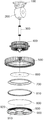
도 1은 본 발명의 일 실시예에 따른 LED 방폭등의 사시도이다.
도 2는 본 발명의 일 실시예에 따른 LED 방폭등의 분해 사시도이다.
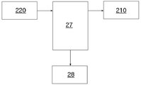
도 3a는 본 발명의 실시예에 따른 LED 구동부의 블록도이다.
도 3b는 본 발명의 실시예에 따른 전원공급장치의 블록도이다.
도 4 내지 도 6은 본 발명의 실시예에 따른 전원공급장치의 회로도이다.
도 7은 본 발명의 실시예에 따른 LED 방폭등의 일 부분에 대한 사시도이다.
도 8 및 도 9는 마운팅 박스를 상부측에서 바라봤을 때, 마운팅 박스 내부의 일부 구성을 개략적으로 도시한 것이다.1 is a perspective view of an LED explosion-proof lamp according to an embodiment of the present invention.
2 is an exploded perspective view of an LED explosion-proof lamp according to an embodiment of the present invention.
3A is a block diagram of an LED driver according to an embodiment of the present invention.
3B is a block diagram of a power supply device according to an embodiment of the present invention.
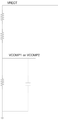
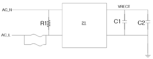
4 to 6 are circuit diagrams of a power supply device according to an embodiment of the present invention.
7 is a perspective view of a part of an LED explosion-proof lamp according to an embodiment of the present invention.
8 and 9 schematically show some configurations inside the mounting box when the mounting box is viewed from the upper side.
본 발명은 다양한 변환을 가할 수 있고 여러 가지 실시예를 가질 수 있는 바, 특정 실시예들을 도면에 예시하고 상세한 설명에 상세하게 설명하고자 한다. 본 발명의 효과 및 특징, 그리고 그것들을 달성하는 방법은 도면과 함께 상세하게 후술되어 있는 실시예들을 참조하면 명확해질 것이다. 그러나 본 발명은 이하에서 개시되는 실시예들에 한정되는 것이 아니라 다양한 형태로 구현될 수 있다. 이하의 실시예에서, 제1, 제2 등의 용어는 한정적인 의미가 아니라 하나의 구성 요소를 다른 구성 요소와 구별하는 목적으로 사용되었다. 또한, 단수의 표현은 문맥상 명백하게 다르게 뜻하지 않는 한, 복수의 표현을 포함한다. 또한, 포함하다 또는 가지다 등의 용어는 명세서상에 기재된 특징, 또는 구성요소가 존재함을 의미하는 것이고, 하나 이상의 다른 특징들 또는 구성요소가 부가될 가능성을 미리 배제하는 것은 아니다. 또한, 도면에서는 설명의 편의를 위하여 구성 요소들이 그 크기가 과장 또는 축소될 수 있다. 예컨대, 도면에서 나타난 각 구성의 크기 및 두께는 설명의 편의를 위해 임의로 나타내었으므로, 본 발명이 반드시 도시된 바에 한정되지 않는다.Since the present invention can apply various transformations and have various embodiments, specific embodiments are illustrated in the drawings and will be described in detail in the detailed description. Effects and features of the present invention, and a method of achieving them will become apparent with reference to the embodiments described below in detail together with the drawings. However, the present invention is not limited to the embodiments disclosed below and may be implemented in various forms. In the following embodiments, terms such as first and second are used for the purpose of distinguishing one constituent element from other constituent elements rather than a limiting meaning. In addition, expressions in the singular include plural expressions unless the context clearly indicates otherwise. In addition, terms such as include or have means that the features or components described in the specification are present, and do not preclude the possibility of adding one or more other features or components in advance. In addition, in the drawings, the size of components may be exaggerated or reduced for convenience of description. For example, the size and thickness of each component shown in the drawings are arbitrarily shown for convenience of description, and thus the present invention is not necessarily limited to what is shown.
이하, 첨부된 도면을 참조하여 본 발명의 실시예들을 상세히 설명하기로 하며, 도면을 참조하여 설명할 때 동일하거나 대응하는 구성 요소는 동일한 도면부호를 부여하고 이에 대한 중복되는 설명은 생략하기로 한다.Hereinafter, embodiments of the present invention will be described in detail with reference to the accompanying drawings, and when describing with reference to the drawings, the same or corresponding constituent elements are assigned the same reference numerals, and redundant descriptions thereof will be omitted. .
도 1은 본 발명의 일 실시예에 따른 LED 방폭등의 사시도이다. 그리고, 도 2는 본 발명의 일 실시예에 따른 LED 방폭등의 분해 사시도이다.1 is a perspective view of an LED explosion-proof lamp according to an embodiment of the present invention. And, Figure 2 is an exploded perspective view of the LED explosion-proof lamp according to an embodiment of the present invention.
본 발명의 일 실시예에 따른 LED 방폭등(10)은 설치할 장소에 고정된 앵커에 고정되는 거치대(100), 거치대(10)에 일체로 형성되어 그 내부에서 전원선이 연결되는 마운팅 박스(200), 마운팅 박스(200)에 일측 선단이 나사 결합되어 전원선의 통로를 이루는 스틸 파이프(300), 스틸 파이프(300)에 장착되는 LED 모듈 구동용 전원장치 케이스(400), 스틸 파이프(300)의 타측 선단에 나사 결합되어 광원에서 발산되는 열을 방출시키는 본체(500), LED가 실장되어 본체(500)의 내부 윗면에 부착 장착되는 LED 모듈(600)과 본체(500) 내에 장착되어 LED의 빛을 반사시키는 반사판(700)과 본체(500) 내외부의 방열을 견디도록 반사판(700) 아래에 삽입되는 유리 지지용 브라켓(810)과 브라켓(810)에 장착되어 반사판(700)을 보호하는 강화유리(800) 및 본체(500)의 하부 내측면에 나사 결합되어 반사판(700)과 브라켓(810) 및 강화유리(800)를 지지하는 유리커버(900)로 구성될 수 있다.The LED explosion-
전원장치 케이스(400)는 필요에 따라 직경에 비해 길이가 긴 원통체 또는 길이에 비해 직경이 긴 원통체로 다양한 형상과 크기로 구성할 수 있다.The
전원장치 케이스(400)는 대략 내부가 빈 원통 형상으로 형성되며, 내부에는 전원공급장치가 내장되며, 전원공급장치로는 형관등 등의 사용시 안정기를 대신하는 LED 램프에 적합한 SMPS(Switching Mode Power Supply)를 사용함으로써 소비전력을 줄이고, 컴팩트한 방폭등을 실현할 수 있게 된다. 본체(500)는 상부면이 위로 볼록하게 이중 단차를 이루어 내부에 중공부를 갖는 원형 캡 형상이고, 효과적인 방열을 위해 상부면 중심부로부터 가장자리로 가면서 4열의 그룹을 이루는 다수의 방열핀이 방사상으로 형성되고, 내부면 윗면에는 LED 모듈(600)이 부착되며, 내부면 하부에 반사판(700)과 유리 지지용 브라켓(810), 강화유리(800)가 장착된 채로 유리커버(900)가 나사결합될 수 있다.The
본체(500)와 방열핀은 LED 모듈(600)에 실장된 LED 램프에서 발생한 열을 효과적으로 방출하기 위해 열전도도가 높은 알루미늄 또는 발포 알루미늄인 것이 바람직하고, 유리 지지용 브라켓(810)은 강화유리(800)의 장착을 위해 사용될 수 있다.The
유리커버(900)는 링형 테두리부와 중심부의 링이 다수의 지지대(910)로 연결되어 지지되고, 상기 테두리부는 직경의 차로 단차를 이루어 짧은 직경의 테두리부 외주연에는 본체(500)의 하부 내측면에 나사 결합되는 나사산(920)이 형성되며, 긴 직경의 테두리부 외주연에는 일정한 간격을 두고 요철의 줄눈(930)이 형성되어 손으로 잡아 본체(500)에 결합시 미끄러짐을 방지하는 것이 바람직하다.The
도 3a는 본 발명의 실시예에 따른 LED 구동부의 블록도이다.3A is a block diagram of an LED driver according to an embodiment of the present invention.
실시예에 따른 LED 구동부는 프로세서(27), 전원공급장치(28)를 포함할 수 있다. 프로세서(27)는 전원공급장치(28)의 구동을 제어할 수 있다. 전원공급장치(28)는 프로세서(27)의 제어하에 외부로부터 공급된 교류 전력을 직류 전력으로 변환하여 LED에 공급함으로써 LED를 구동시킬 수 있다. 또한, 프로세서(27)는 광수신부(220)에서 광을 수신하면, 수신된 광 신호에 기초하여 제어 명령 신호를 검출하고, 해당 제어 명령 신호에 따라 전원공급장치(28)를 제어할 수 있다. 또한, 프로세서(27)는 광수신부(220)에서 광을 수신하면, 수신된 광과 동일한 광이 광출력부(210)를 통해 출력될 수 있도록 광출력부(210)를 제어할 수 있다. 한편, 광수신부(220)는 다른 LED 방폭등의 광출력부를 통해 출력된 광을 수신하거나, 사용자가 조작하는 리모컨 장치로부터 전달된 광을 수신할 수도 있다. 또한, 광출력부(210)는 생성한 광을 다른 LED 방폭등의 광수신부로 전달할 수 있다.The LED driver according to the embodiment may include a
또한, 프로세서(27)는 수신된 제어 명령 신호가 자기 자신의 제어를 위한 명령 신호가 아닌 경우, 전원공급장치(28)를 제어하지 않고, 단지 광출력부(210)를 제어함으로써 수신된 광과 동일한 광이 광출력부(210)를 통해 출력되도록 한다. 따라서, 복수의 LED 방폭등 모두가 순차적으로 제어 명령 신호를 수신할 수 있으나 그 들 중에서 적어도 일부의 LED 방폭등만이 제어될 수 있다.In addition, when the received control command signal is not a command signal for its own control, the
여기서의 제어 명령 신호는 복수의 LED 방폭등 중의 적어도 일부에 대한 LED 구동 개시 또는 LED 구동 중지, LED 밝기 조절 등이 될 수 있다. 다만, 이에 제한되는 것은 아니다.Here, the control command signal may be a start or stop of driving an LED for at least some of the plurality of LED explosion-proof lamps, and an LED brightness control. However, it is not limited thereto.
도 3b는 본 발명의 실시예에 따른 전원공급장치의 블록도이다.3B is a block diagram of a power supply device according to an embodiment of the present invention.
전원공급장치(20)는 인쇄회로기판(20a)과 인쇄회로기판(20a)에 프린팅된 고전압 직류화부(21), 리플제거부(22) 및 전류 안정회로부(23)를 포함할 수 있다. 고전압 직류화부(21)는 브릿지 회로로 구성될 수 있다. 고전압 직류화부(21)는 입력되는 교류 신호를 직류 신호로 변환할 수 있다. 리플제거부(22)는 평활 콘텐서로 구성될 수 있다. 리플제거부(22)는 입력되는 직류 신호에 포함된 리플을 제거할 수 있다. 또한, 전류 안정회로부(23)는 RC 병렬 회로로 구성될 수 있다. 전류 안정회로부(23)는 고전압의 직류 신호를 출력할 수 있다.The power supply device 20 may include a printed circuit board 20a, a high voltage direct
본 발명의 실시예에 따른 전원공급장치(20)는 전해콘덴서가 아닌 평활 콘덴서를 이용하여 직류 신호에 포함된 리플을 제거하도록 한다.The power supply device 20 according to the embodiment of the present invention uses a smoothing capacitor, not an electrolytic capacitor, to remove ripple included in a DC signal.
전해 콘덴서의 경우 저온 및 고온에서 얼었다 녹았다를 반복함에 따라 전원공급장치 및 LED의 전체적인 수명을 줄이는 현상이 나타나는 문제를 해결하고자 본 발명의 전원공급장치(20)는 전해콘덴서 대신 평활콘덴서를 이용한다.In the case of an electrolytic capacitor, the power supply device 20 of the present invention uses a smoothing capacitor instead of an electrolytic capacitor in order to solve the problem of reducing the overall life of the power supply device and the LED by repeating freezing and melting at low and high temperatures. .
또한, 본 발명의 실시예에 따른 인쇄회로기판(20a)은 에폭시 재질로 구성될 수 있다. 이러한 에폭시 재질의 기판은 회로부에서 발생한 열을 기판의 뒷면으로 유도하여 열을 방출할 수 있어 발열 문제를 해결할 수 있다.In addition, the printed circuit board 20a according to the embodiment of the present invention may be made of an epoxy material. Such an epoxy-based substrate can emit heat by inducing heat generated from the circuit portion to the back side of the substrate, thereby solving the heat generation problem.
또한, 본 발명의 실시예에 따른 전원공급장치(20)는 전원장치 케이스(400)에 실장됨으로써 별도의 전원공급장치(20)를 실장치기 위한 다이캐스팅 금형이 불필요해져 경제성이 제고되고 외형적인 투박함이 없어 디자인적 요소를 가미할 수 있는 이점이 있다.In addition, since the power supply device 20 according to the embodiment of the present invention is mounted on the
한편, 전원장치 케이스(400)는 전원공급장치(20)로부터 발생한 열을 효과적으로 방출하기 위해 열전도도가 높은 알루미늄 재질 또는 발포 알루미늄 재질로 이루어질 수 있다.Meanwhile, the
전술한 알루미늄은 99.00% 이상의 순도와, 비중(20℃) 2.6986, 용융점(℃) 660.2, 비열(100℃)(cal/g ℃) 0.226, 잠열(cal/g) 96.4, 전기전도도(%) 69.94, 전기저항온도계수 0.00429를 갖는 것일 수 있다.The above-described aluminum has a purity of 99.00% or more, specific gravity (20°C) 2.6986, melting point (°C) 660.2, specific heat (100°C) (cal/g°C) 0.226, latent heat (cal/g) 96.4, electrical conductivity (%) 69.94 , It may have an electrical resistance temperature coefficient of 0.00429.
또한, 발포 알루미늄은 순도 99%이상의 알루미늄 괴(Ingot)을 원료로 하여 670 ~ 690℃의 온도범위에서 알루미늄을 용해시킨 후, 증점제인 Ca powder를 용해된 알루미늄에 대하여 1.0 ~ 2.0wt%로 첨가하여 600rpm으로 5~ 10분간 교반한 후, MgH2, TiH2 발포제를 0.5 ~ 2.5wt%로 첨가하여 1,000rpm으로 2 ~ 3분간 교반하여 발포시키고, 발포알루미늄의 제조에 있어서는 증점제의 양이 1.0wt% 미만인 경우에 점도의 조절이 원활하게 이루어지지 않아 발포 특성이 떨어질 수 있고, 2.0wt%를 초과하게 되는 경우에는 필요 이상으로 사용하게 되어 무의미하므로, 상기 증점제의 양은 1.0 ~ 2.0wt%의 범위 내로 한정할 수 있다.In addition, foamed aluminum is made from aluminum ingots with a purity of 99% or higher as a raw material, and after dissolving aluminum in a temperature range of 670 to 690°C, Ca powder, a thickener, is added to the dissolved aluminum in an amount of 1.0 to 2.0 wt%. After stirring at 600 rpm for 5 to 10 minutes, MgH2, TiH2 foaming agent is added at 0.5 to 2.5 wt%, stirred at 1,000 rpm for 2 to 3 minutes to foam, and in the production of aluminum foam, when the amount of the thickener is less than 1.0 wt% Since the viscosity is not smoothly adjusted, the foaming properties may be deteriorated, and if it exceeds 2.0wt%, it is used more than necessary and is meaningless, so the amount of the thickener can be limited within the range of 1.0 to 2.0wt%. have.
도 4 내지 도 6은 본 발명의 실시예에 따른 전원공급장치의 회로도이다.4 to 6 are circuit diagrams of a power supply device according to an embodiment of the present invention.
도 4 내지 도 6을 참조하면, 전원공급장치(20)는 제1 내지 제6 AC 다이렉트칩(31, 32, 33, 34, 35, 36), 전원공급장치(20)는 전압직류화부(40) 및 전압분배부(50)로 구성될 수 있다.4 to 6, the power supply device 20 includes first to sixth AC
제1 내지 제6 AC 다이렉트칩(31, 32, 33, 34, 35, 36) 각각은 제1 내지 제4 채널 단자(CH1, CH2, CH3, CH4), VAC단자, NC단자, VCC단자, TST1단자, VDD단자, GNDA단자, TST2단자, CDLY단자, RISET단자, PDC단자, VCOMP단자를 포함할 수 있다.Each of the first to sixth AC direct chips (31, 32, 33, 34, 35, 36) has the first to fourth channel terminals (CH1, CH2, CH3, CH4), VAC terminal, NC terminal, VCC terminal, TST1 Terminal, VDD terminal, GNDA terminal, TST2 terminal, CDLY terminal, RISET terminal, PDC terminal, VCOMP terminal can be included.
제1 다이렉트칩(31)의 연결관계를 설명한다. VRECT 전압 단자는 두개의 병렬 저항 회로(R11, R12)의 일측 단자로 연결되고, 두개의 병렬 저항 회로(R11, R12)의 타측 단자는 VAC단자에 연결될 수 있다. VCC단자는 두개의 병렬 콘덴서 회로(C11, C12)의 일측 단자에 연결되고, 두개의 병렬 콘덴서 회로(C11, C12)의 타측 단자는 그라운드에 연결된다. TST1단자는 R13저항의 일측에 연결되고, R13저항은 그라운드에 연결된다. VDD단자는 C13 콘덴서의 일측 단자에 연결되고, C13 콘덴서의 타측 단자는 그라운드에 연결된다. GNDA 단자와 TST2 단자는 서로 공통 연결되어 그라운드 단자로 연결된다. PDC단자는 C14 콘덴서의 일측 단자에 연결되고 C14 콘덴서의 타측 단자는 그라운드에 연결된다. RISET단자는 두개의 병렬 저항 회로(R14, R15)의 일측 단자에 연결된다. PDC단자는 C15 콘덴서의 일측 단자에 연결되고, C15 콘덴서의 타측 단자는 그라운드 단자로 연결된다. VCOMP단자로는 VCOMP1 전압이 인가된다.The connection relationship between the first
제2 다이렉트칩(32)의 연결관계를 설명한다. VRECT 전압 단자는 두개의 병렬 저항 회로(R21, R22)의 일측 단자로 연결되고, 두개의 병렬 저항 회로(R21, R22)의 타측 단자는 VAC단자에 연결될 수 있다. VCC단자는 두개의 병렬 콘덴서 회로(C21, C22)의 일측 단자에 연결되고, 두개의 병렬 콘덴서 회로(C21, C22)의 타측 단자는 그라운드에 연결된다. TST1단자는 R23저항의 일측에 연결되고, R23저항은 그라운드에 연결된다. VDD단자는 C23 콘덴서의 일측 단자에 연결되고, C23 콘덴서의 타측 단자는 그라운드에 연결된다. GNDA 단자와 TST2 단자는 서로 공통 연결되어 R26 저항의 일측 단자로 연결되고, R26 저항의 타측 단자는 그라운드 단자로 연결된다. PDC단자는 C24 콘덴서의 일측 단자에 연결되고 C24 콘덴서의 타측 단자는 그라운드에 연결된다. RISET단자는 R27 저항의 일측 단자에 연결되고, R27 저항의 타측 단자는 두개의 병렬 저항 회로(R24, R25)의 일측 단자에 연결된다. PDC단자는 C25 콘덴서의 일측 단자에 연결되고, C25 콘덴서의 타측 단자는 그라운드 단자로 연결된다. VCOMP단자로는 VCOMP1 전압이 인가된다.The connection relationship between the second direct chip 32 will be described. The VRECT voltage terminal may be connected to one terminal of the two parallel resistance circuits R21 and R22, and the other terminal of the two parallel resistance circuits R21 and R22 may be connected to the VAC terminal. The VCC terminal is connected to one terminal of the two parallel capacitor circuits C21 and C22, and the other terminal of the two parallel capacitor circuits C21 and C22 is connected to the ground. TST1 terminal is connected to one side of R23 resistance, and R23 resistance is connected to ground. The VDD terminal is connected to one terminal of the C23 capacitor, and the other terminal of the C23 capacitor is connected to ground. The GNDA terminal and the TST2 terminal are connected to each other in common and connected to one terminal of the R26 resistor, and the other terminal of the R26 resistor to the ground terminal. The PDC terminal is connected to one terminal of the C24 capacitor and the other terminal of the C24 capacitor is connected to the ground. The RISET terminal is connected to one terminal of the R27 resistor, and the other terminal of the R27 resistor is connected to one terminal of the two parallel resistance circuits R24 and R25. The PDC terminal is connected to one terminal of the C25 capacitor, and the other terminal of the C25 capacitor is connected to the ground terminal. VCOMP1 voltage is applied to the VCOMP terminal.
제3 다이렉트칩(33)의 연결관계를 설명한다. VRECT 전압 단자는 두개의 병렬 저항 회로(R31, R32)의 일측 단자로 연결되고, 두개의 병렬 저항 회로(R31, R32)의 타측 단자는 VAC단자에 연결될 수 있다. VCC단자는 두개의 병렬 콘덴서 회로(C31, C32)의 일측 단자에 연결되고, 두개의 병렬 콘덴서 회로(C31, C32)의 타측 단자는 그라운드에 연결된다. TST1단자는 R33저항의 일측에 연결되고, R33저항은 그라운드에 연결된다. VDD단자는 C33 콘덴서의 일측 단자에 연결되고, C33 콘덴서의 타측 단자는 그라운드에 연결된다. GNDA 단자와 TST2 단자는 서로 공통 연결되어 R36 저항의 일측 단자로 연결되고, R36 저항의 타측 단자는 그라운드 단자로 연결된다. PDC단자는 C34 콘덴서의 일측 단자에 연결되고 C34 콘덴서의 타측 단자는 그라운드에 연결된다. RISET단자는 두개의 병렬 저항 회로(R34, R35)의 일측 단자에 연결된다. PDC단자는 C35 콘덴서의 일측 단자에 연결되고, C35 콘덴서의 타측 단자는 그라운드 단자로 연결된다. VCOMP단자로는 VCOMP2 전압이 인가된다.The connection relationship between the third
제4 다이렉트칩(34)의 연결관계를 설명한다. VRECT 전압 단자는 두개의 병렬 저항 회로(R41, R42)의 일측 단자로 연결되고, 두개의 병렬 저항 회로(R41, R42)의 타측 단자는 VAC단자에 연결될 수 있다. VCC단자는 두개의 병렬 콘덴서 회로(C41, C42)의 일측 단자에 연결되고, 두개의 병렬 콘덴서 회로(C41, C42)의 타측 단자는 그라운드에 연결된다. TST1단자는 R43저항의 일측에 연결되고, R43저항은 그라운드에 연결된다. VDD단자는 C43 콘덴서의 일측 단자에 연결되고, C43 콘덴서의 타측 단자는 그라운드에 연결된다. GNDA 단자와 TST2 단자는 서로 공통 연결되어 R46 저항의 일측 단자로 연결되고, R46 저항의 타측 단자는 그라운드 단자로 연결된다. PDC단자는 C44 콘덴서의 일측 단자에 연결되고 C44 콘덴서의 타측 단자는 그라운드에 연결된다. RISET단자는 R47 저항의 일측 단자에 연결되고, R47 저항의 타측 단자는 두개의 병렬 저항 회로(R44, R45)의 일측 단자에 연결된다. PDC단자는 C45 콘덴서의 일측 단자에 연결되고, C45 콘덴서의 타측 단자는 그라운드 단자로 연결된다. VCOMP단자로는 VCOMP2 전압이 인가된다.The connection relationship between the fourth
또한, R14, R15의 병렬 저항 회로, R24, R25의 병렬 저항 회로, R34, R35의 병렬 저항 회로, R34, R35의 병렬 저항 회로 각각의 타측 단자(A)는 제5 및 제6 AC 다이렉트칩(35, 36)의 A 단자에 연결된다.In addition, the other terminal A of each of the parallel resistance circuits of R14 and R15, the parallel resistance circuits of R24 and R25, the parallel resistance circuits of R34 and R35, and the parallel resistance circuits of R34 and R35 is the fifth and sixth AC direct chip ( It is connected to A terminal of 35, 36).
제5 다이렉트칩(35)의 연결관계를 설명한다. VRECT 전압 단자는 두개의 병렬 저항 회로(R51, R52)의 일측 단자로 연결되고, 두개의 병렬 저항 회로(R51, R52)의 타측 단자는 VAC단자에 연결될 수 있다. VCC단자는 두개의 병렬 콘덴서 회로(C51, C52)의 일측 단자에 연결되고, 두개의 병렬 콘덴서 회로(C51, C52)의 타측 단자는 그라운드에 연결된다. TST1단자는 R53저항의 일측에 연결되고, R53저항은 그라운드에 연결된다. VDD단자는 C53 콘덴서의 일측 단자에 연결되고, C53 콘덴서의 타측 단자는 그라운드에 연결된다. GNDA 단자와 TST2 단자는 서로 공통 연결되어 그라운드 단자로 연결된다. PDC단자는 C54 콘덴서의 일측 단자에 연결되고 C54 콘덴서의 타측 단자는 그라운드에 연결된다. RISET단자는 두개의 병렬 저항 회로(R54, R55)의 일측 단자에 연결된다. PDC단자는 C55 콘덴서의 일측 단자에 연결되고, C55 콘덴서의 타측 단자는 그라운드 단자로 연결된다. VCOMP단자로는 VCOMP1 전압이 인가된다.The connection relationship between the fifth
제6 다이렉트칩(36)의 연결관계를 설명한다. VRECT 전압 단자는 두개의 병렬 저항 회로(R61, R62)의 일측 단자로 연결되고, 두개의 병렬 저항 회로(R61, R62)의 타측 단자는 VAC단자에 연결될 수 있다. VCC단자는 두개의 병렬 콘덴서 회로(C61, C62)의 일측 단자에 연결되고, 두개의 병렬 콘덴서 회로(C61, C62)의 타측 단자는 그라운드에 연결된다. TST1단자는 R63저항의 일측에 연결되고, R63저항은 그라운드에 연결된다. VDD단자는 C63 콘덴서의 일측 단자에 연결되고, C63 콘덴서의 타측 단자는 그라운드에 연결된다. GNDA 단자와 TST2 단자는 서로 공통 연결되어 R66 저항의 일측 단자로 연결되고, R66 저항의 타측 단자는 그라운드 단자로 연결된다. PDC단자는 C64 콘덴서의 일측 단자에 연결되고 C64 콘덴서의 타측 단자는 그라운드에 연결된다. RISET단자는 두개의 병렬 저항 회로(R64, R65)의 일측 단자에 연결된다. PDC단자는 C65 콘덴서의 일측 단자에 연결되고, C65 콘덴서의 타측 단자는 그라운드 단자로 연결된다. VCOMP단자로는 VCOMP2 전압이 인가된다.The connection relationship between the sixth
R54, R55 저항 회로, R64, R65 저항 회로 각각의 타측 단자는 A 단자에 연결된다.The other terminal of each of the R54, R55 resistance circuits, and R64, R65 resistance circuits is connected to the A terminal.
또한, 고전압 직류화부(21)의 일측 포트로는 외부로부터의 교류 전압이 인가되고, 교류 전압 인가를 위한 두 개의 전원 라인 사이에는 제1 저항(R1)이 연결되며, 교류 전압 인가를 위한 두 개의 전원 라인 중 하나의 라인의 경로 상에는 병렬 연결의 두개의 퓨즈가 설치될 수 있다.In addition, an AC voltage from the outside is applied to one port of the high
고전압 직류화부(21)의 타측 포트 사이에는 제1 및 제2 콘덴서(C1, C2)가 연결된다. 타측 포트 각각에 연결된 전원 라인 중 하나의 라인은 그라운드 단자에 연결된다. 즉, 제1 및 제2 콘덴서(C1, C2)의 타측 단자는 그라운드 단자에 연결되고, 일측 단자에서 VRECT 전압이 출력된다.First and second capacitors C1 and C2 are connected between the other ports of the high
또한, VRECT 전압은 두개의 직렬 저항 회로의 일측 단자에 인가되고, 두개의 직렬 저항 회로의 타측 단자는 RC 병렬 회로의 일측 단자에 연결되며 RC 병렬 회로의 타측 단자는 그라운드에 연결되다. 그리고 RC 병렬 회로의 일측 단자로부터 VCOMP1 또는 VCOMP2 전압이 출력된다.In addition, the VRECT voltage is applied to one terminal of the two series resistance circuits, the other terminal of the two series resistance circuits is connected to one terminal of the RC parallel circuit, and the other terminal of the RC parallel circuit is connected to ground. And the voltage VCOMP1 or VCOMP2 is outputted from one terminal of the RC parallel circuit.
제1 내지 제6 AC 다이렉트칩(31, 32, 33, 34, 35, 36) 각각의 제1 내지 제4 채널 단자(CH1, CH2, CH3, CH4)로부터의 출력 전압은 LED로 공급되어 LED를 구동시킬 수 있다.The output voltages from the first to fourth channel terminals (CH1, CH2, CH3, CH4) of each of the first to sixth AC
도 7은 본 발명의 실시예에 따른 LED 방폭등의 일 부분에 대한 사시도이고, 도 8 및 도 9는 마운팅 박스를 상부측에서 바라봤을 때, 마운팅 박스 내부의 일부 구성을 개략적으로 도시한 것이다.7 is a perspective view of a part of an LED explosion-proof lamp according to an embodiment of the present invention, and FIGS. 8 and 9 schematically illustrate a part of the interior of the mounting box when viewed from the top.
도 7 내지 도 9를 참조하면, 마운팅 박스(200)는 원기둥 형상을 가질 수 있다. 마운팅 박스(200)의 상부면에는 광출력 영역(201)이 형성되고, 하부면에는 광수신 영역(202)이 형성될 수 있다.7 to 9, the mounting
광출력 영역(201) 및 광수신 영역(202) 각각은 유리커버로 형성됨으로써 마운팅 박스(200)의 내부로부터의 광이 출력될 수 있고, 또한 외부로부터의 광이 마운팅 박스(200) 내부로 입력될 수 있다.Each of the
마운팅 박스(200) 내부에는 광출력부(210)와 광수신부(220)가 설치될 수 있다. 또한, 마운팅 박스(200) 내부에는 광출력부(210)를 통해 출력된 광을 반사시키는 제1 반사부(211) 및 외부로부터 마운팅 박스(200) 내부로 입력된 광을 반사하여 광수신부(220)로 제공하는 제2 반사부(221)가 더 설치될 수 있다.An
제1 반사부(211)는 광출력부(210)를 통해 출력된 광이 광출력 영역(201)을 통해 출력되도록 광출력부(210)로부터 제공된 광을 반사할 수 있다. The first reflecting
또한, 마운팅 박스(200)의 외측에는 제1 및 제2 반사부 위치 조절부(203, 204)가 더 설치될 수 있다. 제1 반사부 위치 조절부(203)를 조작하여 제1 반사부(211)를 소정의 각도 범위 내에서 회전시킬 수 있다. 또한, 제1 반사부(211)는 수신된 광을 반사하여 반사된 광이 광출력 영역(201)을 통해 출력될 수 있도록 소정의 각도 범위 내에서 회전할 수 있다.In addition, the first and second reflector
또한, 제2 반사부 위치 조절부(204)를 조작하여 제2 반사부(221)를 소정의 각도 범위 내에서 회전시킬 수 있다. 또한, 제2 반사부(221)는 수신된 광을 반사하여 반사된 광이 광수신부(220)으로 출력될 수 있도록 소정의 각도 범위 내에서 회전할 수 있다.In addition, the
사용자는 제1 및 제2 반사부 위치 조절부(203, 204) 각각을 회전시키면 이에 대응하여 제1 및 제2 반사부(211, 221) 각각이 회전할 수 있도록 구성될 수 있다.When the user rotates each of the first and second reflective unit
일부 실시예에 따르면, 마운팅 박스(200)의 상부면의 광출력 영역(201)과 인접한 영역에 광가이드부(241)가 설치될 수 있는 광가이드부 설치장치(240)가 설치될 수 있다. 또한, 마운팅 박스(200)의 하부면의 광수신 영역(202)과 인접한 영역에 광가이드부(241)가 설치될 수 있는 광가이드부 설치장치(240)가 설치될 수 있다. 광가이드부 설치장치(240)는 마운팅 박스(200) 상부면 및 하부면 각각에 복수개로 구비되고, 상부면 및 하부면 각각의 복수개의 광가이드부 설치장치(240) 중 적어도 하나에 광가이드부(241)를 결합할 수 있다.According to some embodiments, the light guide
광출력 영역(201)에 인접하여 설치된 광가이드부 설치장치(240)에 결합된 광가이드부(241)는 광출력 영역(201)으로부터 출력된 광을 반사한다. 그리고, 광가이드부(241)가 마운팅 박스(200)의 상부면과 이루는 각도에 따라서 다양한 경로로 광을 반사할 수 있다. 또한, 광수신 영역(202)에 인접하여 설치된 광가이드부 설치장치(240)에 결합된 광가이드부(241)는 외부로부터 수신된 광을 광수신 영역(202)으로 반사한다. 그리고, 광가이드부(241)가 마운팅 박스(200)의 상부면과 이루는 각도에 따라서 다양한 경로로 광을 반사할 수 있다.The
산업 현장에 소정의 공간에 복수개의 LED 방폭등이 설치될 때, 복수개의 LED 방폭등 중 어느 하나의 LED 방폭등에서, 광출력부(210)를 통해 출력된 광은 제1 반사부(211)에서 반사되어 또는 제1 반사부(211)와 광가이드부(241)에서 순차적으로 반사되어 외부로 출력될 수 있다. 외부로 출력된 광은 인접한 다른 LED 방폭등의 광가이드부(241)와 제2 반사부(221)에서 순차적으로 반사되어 또는 제2 반사부(221)에서 반사되어 해당 LED 방폭등의 광수신부(220)로 입력될 수 있다.When a plurality of LED explosion-proof lamps are installed in a predetermined space in an industrial site, in any one of the plurality of LED explosion-proof lamps, the light output through the
또한, 복수개의 LED 방폭등의 상호간의 위치 관계에 따라서 제1 및 제2 반사부(211, 221)를 회전시키고, 필요에 따라서 광가이드부(241)를 추가로 광가이드부 설치장치(240)에 설치함으로써 어느 하나의 LED 방폭등에서 출력된 광은 인접한 LED 방폭등으로 전달되는 과정을 진행함으로써 최종적으로 모든 LED 방폭등이 광을 수신할 수 있도록 한다.In addition, the first and second reflecting
또한, 사용자는 복수개의 LED 방폭등 중 메인 LED 방폭등의 광수신부(220)에 광을 제공하면, 광을 수신한 메인 LED 방폭등은 인접한 다른 LED 방폭등에 광을 전달함으로써 결과적으로 모든 LED 방폭등이 광을 수신할 수 있도록 한다. 그리고, 사용자는 리모컨 장치를 이용하여 광을 생성할 수 있다. 여기서의 사용자가 리모컨 장치에 마련된 복수의 입력 버튼 중 어느 하나의 버튼을 조작함에 따라 조작된 버튼과 매칭된 제어 명령 신호를 가지는 광이 리모컨 장치로부터 생성되어 리모컨 장치로부터 출력되고, 출력된 광은 메인 LED 방폭등으로 전달된다.In addition, when the user provides light to the
본 발명은 LED 방폭등 자체에 LED 방폭등의 전원이나 LED의 발광 정도를 조절할 수 있는 장치를 구비하지 않아도 전술한 광 신호의 순차적인 전달을 통해 복수개의 LED 방폭등 전체 또는 적어도 일부를 제어할 수 있다. LED 방폭등을 제어할 수 있는 장치를 마련함에 따라 미세한 간극이나 조작 장치의 조작에 따른 밀폐 구조의 일시적인 해제 등에 따라 LED 방폭등의 폭발 등의 위험이 발생할 수 있는 문제를 원천적으로 차단할 수 있다.The present invention can control all or at least a part of a plurality of LED explosion-proof lamps through sequential transmission of the above-described optical signals, even if the LED explosion-proof lamp itself does not have a power supply of the LED explosion-proof lamp or a device capable of controlling the degree of light emission of the LED. have. By providing a device that can control the LED explosion-proof lamp, it is possible to fundamentally block the problem that may cause the risk of explosion of the LED explosion-proof lamp due to a minute gap or temporary release of the sealed structure due to the manipulation of the operation device.
본 발명의 상세한 설명에서는 본 발명의 바람직한 실시 예를 참조하여 설명하였지만, 해당 기술 분야의 숙련된 당업자 또는 해당 기술분야에 통상의 지식을 갖는 자라면 후술할 특허청구범위에 기재된 본 발명의 사상 및 기술 영역으로부터 벗어나지 않는 범위 내에서 본 발명을 다양하게 수정 및 변경시킬 수 있음을 이해할 수 있을 것이다. 따라서, 본 발명의 기술적 범위는 명세서의 상세한 설명에 기재된 내용으로 한정되는 것이 아니라 특허청구범위에 의해 정하여져야만 할 것이다.In the detailed description of the present invention, although it has been described with reference to a preferred embodiment of the present invention, the spirit and technology of the present invention described in the claims to be described later if a person skilled in the relevant technical field or a person of ordinary skill in the relevant technical field It will be appreciated that various modifications and changes can be made to the present invention without departing from the scope. Therefore, the technical scope of the present invention should not be limited to the contents described in the detailed description of the specification, but should be determined by the claims.
Claims (10)
상기 거치대에 일체로 형성되어 그 내부에 전원선이 연결되는 마운팅 박스;
상기 마운팅 박스에 일측 선단이 나사 결합되어 전원선의 통로를 이루는 스틸 파이프;
상기 스틸 파이프에 장착되는 LED 모듈 구동용 전원장치케이스;
상기 스틸 파이프의 타측 선단에 나사 결합되어 광원에서 발산되는 열을 방출시키는 본체; 및
LED가 실장되어 상기 본체의 내부 윗면에 부착 장착되는 LED 모듈;을 포함하고,
상기 전원장치케이스는 입력된 교류 신호를 직류로 변환하는 고전압 직류화부, 고전압 직류화부로부터 출력된 직류 신호의 리플을 제거하는 리플제거부 및 상기 리플제거부와 연결되어 직류 신호를 출력하는 전류 안정회로부를 포함하는
LED 방폭등.A cradle fixed to the anchor fixed to the place to be installed;
A mounting box integrally formed with the cradle to which a power line is connected therein;
A steel pipe having one end screwed to the mounting box to form a passage for a power line;
A power supply case for driving an LED module mounted on the steel pipe;
A body screwed to the other end of the steel pipe to emit heat emitted from a light source; And
Including; an LED module mounted on the LED is attached to and mounted on the inner upper surface of the main body,
The power supply case includes a high voltage DC converter for converting an input AC signal to DC, a ripple removal part for removing ripple from the DC signal output from the high voltage DC converter, and a current stabilization circuit part connected to the ripple removal part to output a DC signal. Including
LED explosion-proof light.
상기 전원장치케이스는
상기 고전압 직류화부, 상기 리플제거부 및 상기 전류 안정회로부가 프린팅된 인쇄회로기판을 포함하는
LED 방폭등.The method of claim 1,
The power supply case
And a printed circuit board on which the high voltage direct current converter, the ripple removal unit, and the current stabilization circuit part are printed.
LED explosion-proof light.
상기 인쇄회로기판은 에폭시 재질인
LED 방폭등.The method of claim 2,
The printed circuit board is made of epoxy
LED explosion-proof light.
상기 리플제거부는
전해콘덴서를 포함하지 않고, 평활콘덴서를 포함하는
LED 방폭등.The method of claim 1,
The ripple removal unit
Not including electrolytic capacitors, including smoothing capacitors
LED explosion-proof light.
상기 고전압 직류화부는 브릿지 회로로 구성된
LED 방폭등.The method of claim 1,
The high voltage DC converter is composed of a bridge circuit.
LED explosion-proof light.
상기 전류 안정회로부는 저항과 콘덴서로 구성된
LED 방폭등.The method of claim 1,
The current stabilization circuit unit consists of a resistor and a capacitor.
LED explosion-proof light.
상기 마운팅 박스는
원통형으로 구성되고,
상부면에는 상기 마운팅 박스 내부로부터의 광을 출력하는 광출력 영역이 형성되고,
하부면에는 인접한 다른 LED 방폭등 또는 리모컨 장치로부터 제공된 광을 수신하는 광수신 영역이 형성되는
LED 방폭등.The method of claim 1,
The mounting box is
It is composed of a cylindrical shape,
A light output area for outputting light from the inside of the mounting box is formed on the upper surface,
On the lower surface, a light-receiving area for receiving light from other adjacent LED explosion-proof lights or remote control devices is formed.
LED explosion-proof light.
상기 마운팅 박스 내부에 설치되어 상기 광을 생성하는 광출력부;를 더 포함하는
LED 방폭등The method of claim 7,
A light output unit installed inside the mounting box to generate the light; further comprising
LED explosion-proof light
상기 마운팅 박스 내부에 설치되어 상기 다른 LED 방폭등 또는 리모컨 장치로부터 제공된 광을 수신하는 광수신부;를 더 포함하는
LED 방폭등The method of claim 8,
A light receiving unit installed inside the mounting box to receive light provided from the other LED explosion-proof lamp or remote control device; further comprising
LED explosion-proof light
상기 본체는 알루미늄 또는 발포 알루미늄의 재질인
LED 방폭등.
The method of claim 1,
The body is made of aluminum or foamed aluminum.
LED explosion-proof light.
Priority Applications (1)
| Application Number | Priority Date | Filing Date | Title |
|---|---|---|---|
| KR1020190109318A KR102325302B1 (en) | 2019-09-04 | 2019-09-04 | Explosion-proof LED Lamp |
Applications Claiming Priority (1)
| Application Number | Priority Date | Filing Date | Title |
|---|---|---|---|
| KR1020190109318A KR102325302B1 (en) | 2019-09-04 | 2019-09-04 | Explosion-proof LED Lamp |
Publications (2)
| Publication Number | Publication Date |
|---|---|
| KR20210028362A true KR20210028362A (en) | 2021-03-12 |
| KR102325302B1 KR102325302B1 (en) | 2021-11-11 |
Family
ID=75177448
Family Applications (1)
| Application Number | Title | Priority Date | Filing Date |
|---|---|---|---|
| KR1020190109318A Active KR102325302B1 (en) | 2019-09-04 | 2019-09-04 | Explosion-proof LED Lamp |
Country Status (1)
| Country | Link |
|---|---|
| KR (1) | KR102325302B1 (en) |
Cited By (1)
| Publication number | Priority date | Publication date | Assignee | Title |
|---|---|---|---|---|
| KR20230027621A (en) | 2021-08-19 | 2023-02-28 | (주)비젼테크 | Explosion-proof Lamp |
Citations (6)
| Publication number | Priority date | Publication date | Assignee | Title |
|---|---|---|---|---|
| KR20050071617A (en) * | 2002-10-24 | 2005-07-07 | 가부시키가이샤 나카가와 겐큐쇼 | Illumination light communication device |
| KR200426160Y1 (en) * | 2006-06-21 | 2006-09-08 | 뉴마린엔지니어링(주) | Light fixture |
| KR20120002293A (en) | 2010-06-30 | 2012-01-05 | (주)이노셈코리아 | LED light source explosion-proof lamp which improves heat dissipation performance by applying explosion-proof luminaire |
| KR101280963B1 (en) * | 2012-11-20 | 2013-07-02 | 유대성 | Led explosion-proof lamp |
| KR20150125357A (en) * | 2014-04-30 | 2015-11-09 | (주)아스트로 | Independently controllable type led explosion-proof lamp |
| KR101703761B1 (en) * | 2015-09-30 | 2017-02-17 | 서울엘이디(주) | Power distribution circuit and power distribution method |
-
2019
- 2019-09-04 KR KR1020190109318A patent/KR102325302B1/en active Active
Patent Citations (6)
| Publication number | Priority date | Publication date | Assignee | Title |
|---|---|---|---|---|
| KR20050071617A (en) * | 2002-10-24 | 2005-07-07 | 가부시키가이샤 나카가와 겐큐쇼 | Illumination light communication device |
| KR200426160Y1 (en) * | 2006-06-21 | 2006-09-08 | 뉴마린엔지니어링(주) | Light fixture |
| KR20120002293A (en) | 2010-06-30 | 2012-01-05 | (주)이노셈코리아 | LED light source explosion-proof lamp which improves heat dissipation performance by applying explosion-proof luminaire |
| KR101280963B1 (en) * | 2012-11-20 | 2013-07-02 | 유대성 | Led explosion-proof lamp |
| KR20150125357A (en) * | 2014-04-30 | 2015-11-09 | (주)아스트로 | Independently controllable type led explosion-proof lamp |
| KR101703761B1 (en) * | 2015-09-30 | 2017-02-17 | 서울엘이디(주) | Power distribution circuit and power distribution method |
Cited By (1)
| Publication number | Priority date | Publication date | Assignee | Title |
|---|---|---|---|---|
| KR20230027621A (en) | 2021-08-19 | 2023-02-28 | (주)비젼테크 | Explosion-proof Lamp |
Also Published As
| Publication number | Publication date |
|---|---|
| KR102325302B1 (en) | 2021-11-11 |
Similar Documents
| Publication | Publication Date | Title |
|---|---|---|
| US8480249B2 (en) | Method and apparatus for providing an LED light for use in hazardous locations | |
| US7950820B2 (en) | Intrinsically safe flashlight | |
| US20050286265A1 (en) | Linear LED housing configuration | |
| KR101280963B1 (en) | Led explosion-proof lamp | |
| EP3140590A1 (en) | Improved led lamps and luminaires | |
| KR200459504Y1 (en) | LED Light Module For Explosion Proof Lamp | |
| US11788710B2 (en) | Explosion protected luminaire | |
| KR101600006B1 (en) | Independently controllable type led explosion-proof lamp | |
| US8297811B2 (en) | Aircraft lamp | |
| KR102325302B1 (en) | Explosion-proof LED Lamp | |
| RU2475673C1 (en) | Explosion-proof light-emitting diode lamp | |
| CN110056814A (en) | Emergency lighting device and the method for reducing emergency lighting device temperature | |
| KR102572969B1 (en) | Device for led lighting typed with explosion protection lens | |
| CN103574397A (en) | LED (Light Emitting Diode) mine explosion-proof locomotive lamp | |
| CN114413198A (en) | High lumen lighting assembly and method for harsh and hazardous locations | |
| KR101615348B1 (en) | Light Emitting Diode Explosion Prevention Lamp For Offshore Plant | |
| RU2476764C1 (en) | Protected high output led spotlight | |
| CN214840467U (en) | Combined middle rod lamp | |
| JP6861362B2 (en) | Lighting device | |
| CN210717124U (en) | Explosion-proof lamp with prism adjustment mechanism | |
| CN211853771U (en) | A Class IIC LED Explosion-Proof Floodlight That Can Realize High Power | |
| CN113701070A (en) | Heat-dissipation high-power explosion-proof LED explosion-proof lamp | |
| EP2112432A1 (en) | Explosion-proof lighting device | |
| CN209725961U (en) | A kind of fire prevention LED lamp that illumination zone is wide | |
| CN202153767U (en) | Explosion-proof night vision integrated camera |
Legal Events
| Date | Code | Title | Description |
|---|---|---|---|
| A201 | Request for examination | ||
| PA0109 | Patent application |
St.27 status event code: A-0-1-A10-A12-nap-PA0109 |
|
| PA0201 | Request for examination |
St.27 status event code: A-1-2-D10-D11-exm-PA0201 |
|
| R17-X000 | Change to representative recorded |
St.27 status event code: A-3-3-R10-R17-oth-X000 |
|
| D13-X000 | Search requested |
St.27 status event code: A-1-2-D10-D13-srh-X000 |
|
| D14-X000 | Search report completed |
St.27 status event code: A-1-2-D10-D14-srh-X000 |
|
| N231 | Notification of change of applicant | ||
| PN2301 | Change of applicant |
St.27 status event code: A-3-3-R10-R13-asn-PN2301 St.27 status event code: A-3-3-R10-R11-asn-PN2301 |
|
| P11-X000 | Amendment of application requested |
St.27 status event code: A-2-2-P10-P11-nap-X000 |
|
| P13-X000 | Application amended |
St.27 status event code: A-2-2-P10-P13-nap-X000 |
|
| R18-X000 | Changes to party contact information recorded |
St.27 status event code: A-3-3-R10-R18-oth-X000 |
|
| E902 | Notification of reason for refusal | ||
| PE0902 | Notice of grounds for rejection |
St.27 status event code: A-1-2-D10-D21-exm-PE0902 |
|
| PG1501 | Laying open of application |
St.27 status event code: A-1-1-Q10-Q12-nap-PG1501 |
|
| E13-X000 | Pre-grant limitation requested |
St.27 status event code: A-2-3-E10-E13-lim-X000 |
|
| P11-X000 | Amendment of application requested |
St.27 status event code: A-2-2-P10-P11-nap-X000 |
|
| P13-X000 | Application amended |
St.27 status event code: A-2-2-P10-P13-nap-X000 |
|
| E701 | Decision to grant or registration of patent right | ||
| PE0701 | Decision of registration |
St.27 status event code: A-1-2-D10-D22-exm-PE0701 |
|
| GRNT | Written decision to grant | ||
| PR0701 | Registration of establishment |
St.27 status event code: A-2-4-F10-F11-exm-PR0701 |
|
| PR1002 | Payment of registration fee |
St.27 status event code: A-2-2-U10-U11-oth-PR1002 Fee payment year number: 1 |
|
| PG1601 | Publication of registration |
St.27 status event code: A-4-4-Q10-Q13-nap-PG1601 |
|
| R18-X000 | Changes to party contact information recorded |
St.27 status event code: A-5-5-R10-R18-oth-X000 |
|
| R18-X000 | Changes to party contact information recorded |
St.27 status event code: A-5-5-R10-R18-oth-X000 |
|
| R17-X000 | Change to representative recorded |
St.27 status event code: A-5-5-R10-R17-oth-X000 |
|
| PR1001 | Payment of annual fee |
St.27 status event code: A-4-4-U10-U11-oth-PR1001 Fee payment year number: 4 |
|
| PN2301 | Change of applicant |
St.27 status event code: A-5-5-R10-R11-asn-PN2301 |
|
| R11 | Change to the name of applicant or owner or transfer of ownership requested |
Free format text: ST27 STATUS EVENT CODE: A-5-5-R10-R11-ASN-PN2301 (AS PROVIDED BY THE NATIONAL OFFICE) |
|
| P14 | Amendment of ip right document requested |
Free format text: ST27 STATUS EVENT CODE: A-5-5-P10-P14-NAP-X000 (AS PROVIDED BY THE NATIONAL OFFICE) |
|
| P14-X000 | Amendment of ip right document requested |
St.27 status event code: A-5-5-P10-P14-nap-X000 |
|
| PN2301 | Change of applicant |
St.27 status event code: A-5-5-R10-R14-asn-PN2301 |
|
| R14 | Transfer of ownership recorded |
Free format text: ST27 STATUS EVENT CODE: A-5-5-R10-R14-ASN-PN2301 (AS PROVIDED BY THE NATIONAL OFFICE) |
|
| P16 | Ip right document amended |
Free format text: ST27 STATUS EVENT CODE: A-5-5-P10-P16-NAP-X000 (AS PROVIDED BY THE NATIONAL OFFICE) |
|
| P16-X000 | Ip right document amended |
St.27 status event code: A-5-5-P10-P16-nap-X000 |
|
| Q16 | A copy of ip right certificate issued |
Free format text: ST27 STATUS EVENT CODE: A-4-4-Q10-Q16-NAP-X000 (AS PROVIDED BY THE NATIONAL OFFICE) |
|
| Q16-X000 | A copy of ip right certificate issued |
St.27 status event code: A-4-4-Q10-Q16-nap-X000 |
|
| R18 | Changes to party contact information recorded |
Free format text: ST27 STATUS EVENT CODE: A-5-5-R10-R18-OTH-X000 (AS PROVIDED BY THE NATIONAL OFFICE) |
|
| R18-X000 | Changes to party contact information recorded |
St.27 status event code: A-5-5-R10-R18-oth-X000 |
|
| R18 | Changes to party contact information recorded |
Free format text: ST27 STATUS EVENT CODE: A-5-5-R10-R18-OTH-X000 (AS PROVIDED BY THE NATIONAL OFFICE) |
|
| R18-X000 | Changes to party contact information recorded |
St.27 status event code: A-5-5-R10-R18-oth-X000 |
|
| P14-X000 | Amendment of ip right document requested |
St.27 status event code: A-5-5-P10-P14-nap-X000 |