EP2112402A1 - Actionneur à tige principale et tige auxiliaire - Google Patents
Actionneur à tige principale et tige auxiliaire Download PDFInfo
- Publication number
- EP2112402A1 EP2112402A1 EP09290261A EP09290261A EP2112402A1 EP 2112402 A1 EP2112402 A1 EP 2112402A1 EP 09290261 A EP09290261 A EP 09290261A EP 09290261 A EP09290261 A EP 09290261A EP 2112402 A1 EP2112402 A1 EP 2112402A1
- Authority
- EP
- European Patent Office
- Prior art keywords
- rod
- auxiliary rod
- actuator
- main
- main rod
- Prior art date
- Legal status (The legal status is an assumption and is not a legal conclusion. Google has not performed a legal analysis and makes no representation as to the accuracy of the status listed.)
- Granted
Links
Images

Classifications
-
- F—MECHANICAL ENGINEERING; LIGHTING; HEATING; WEAPONS; BLASTING
- F16—ENGINEERING ELEMENTS AND UNITS; GENERAL MEASURES FOR PRODUCING AND MAINTAINING EFFECTIVE FUNCTIONING OF MACHINES OR INSTALLATIONS; THERMAL INSULATION IN GENERAL
- F16H—GEARING
- F16H25/00—Gearings comprising primarily only cams, cam-followers and screw-and-nut mechanisms
- F16H25/18—Gearings comprising primarily only cams, cam-followers and screw-and-nut mechanisms for conveying or interconverting oscillating or reciprocating motions
- F16H25/20—Screw mechanisms
- F16H25/22—Screw mechanisms with balls, rollers, or similar members between the co-operating parts; Elements essential to the use of such members
- F16H25/2247—Screw mechanisms with balls, rollers, or similar members between the co-operating parts; Elements essential to the use of such members with rollers
- F16H25/2252—Planetary rollers between nut and screw
-
- F—MECHANICAL ENGINEERING; LIGHTING; HEATING; WEAPONS; BLASTING
- F16—ENGINEERING ELEMENTS AND UNITS; GENERAL MEASURES FOR PRODUCING AND MAINTAINING EFFECTIVE FUNCTIONING OF MACHINES OR INSTALLATIONS; THERMAL INSULATION IN GENERAL
- F16H—GEARING
- F16H25/00—Gearings comprising primarily only cams, cam-followers and screw-and-nut mechanisms
- F16H25/18—Gearings comprising primarily only cams, cam-followers and screw-and-nut mechanisms for conveying or interconverting oscillating or reciprocating motions
- F16H25/20—Screw mechanisms
- F16H25/2056—Telescopic screws with at least three screw members in coaxial arrangement
-
- F—MECHANICAL ENGINEERING; LIGHTING; HEATING; WEAPONS; BLASTING
- F16—ENGINEERING ELEMENTS AND UNITS; GENERAL MEASURES FOR PRODUCING AND MAINTAINING EFFECTIVE FUNCTIONING OF MACHINES OR INSTALLATIONS; THERMAL INSULATION IN GENERAL
- F16H—GEARING
- F16H25/00—Gearings comprising primarily only cams, cam-followers and screw-and-nut mechanisms
- F16H25/18—Gearings comprising primarily only cams, cam-followers and screw-and-nut mechanisms for conveying or interconverting oscillating or reciprocating motions
- F16H25/20—Screw mechanisms
- F16H25/24—Elements essential to such mechanisms, e.g. screws, nuts
- F16H25/2454—Brakes; Rotational locks
-
- H—ELECTRICITY
- H02—GENERATION; CONVERSION OR DISTRIBUTION OF ELECTRIC POWER
- H02K—DYNAMO-ELECTRIC MACHINES
- H02K7/00—Arrangements for handling mechanical energy structurally associated with dynamo-electric machines, e.g. structural association with mechanical driving motors or auxiliary dynamo-electric machines
- H02K7/06—Means for converting reciprocating motion into rotary motion or vice versa
-
- F—MECHANICAL ENGINEERING; LIGHTING; HEATING; WEAPONS; BLASTING
- F16—ENGINEERING ELEMENTS AND UNITS; GENERAL MEASURES FOR PRODUCING AND MAINTAINING EFFECTIVE FUNCTIONING OF MACHINES OR INSTALLATIONS; THERMAL INSULATION IN GENERAL
- F16H—GEARING
- F16H25/00—Gearings comprising primarily only cams, cam-followers and screw-and-nut mechanisms
- F16H25/18—Gearings comprising primarily only cams, cam-followers and screw-and-nut mechanisms for conveying or interconverting oscillating or reciprocating motions
- F16H25/20—Screw mechanisms
- F16H2025/2062—Arrangements for driving the actuator
- F16H2025/2075—Coaxial drive motors
-
- Y—GENERAL TAGGING OF NEW TECHNOLOGICAL DEVELOPMENTS; GENERAL TAGGING OF CROSS-SECTIONAL TECHNOLOGIES SPANNING OVER SEVERAL SECTIONS OF THE IPC; TECHNICAL SUBJECTS COVERED BY FORMER USPC CROSS-REFERENCE ART COLLECTIONS [XRACs] AND DIGESTS
- Y10—TECHNICAL SUBJECTS COVERED BY FORMER USPC
- Y10T—TECHNICAL SUBJECTS COVERED BY FORMER US CLASSIFICATION
- Y10T74/00—Machine element or mechanism
- Y10T74/18—Mechanical movements
- Y10T74/18568—Reciprocating or oscillating to or from alternating rotary
- Y10T74/18576—Reciprocating or oscillating to or from alternating rotary including screw and nut
- Y10T74/186—Alternate power path operable on failure of primary
-
- Y—GENERAL TAGGING OF NEW TECHNOLOGICAL DEVELOPMENTS; GENERAL TAGGING OF CROSS-SECTIONAL TECHNOLOGIES SPANNING OVER SEVERAL SECTIONS OF THE IPC; TECHNICAL SUBJECTS COVERED BY FORMER USPC CROSS-REFERENCE ART COLLECTIONS [XRACs] AND DIGESTS
- Y10—TECHNICAL SUBJECTS COVERED BY FORMER USPC
- Y10T—TECHNICAL SUBJECTS COVERED BY FORMER US CLASSIFICATION
- Y10T74/00—Machine element or mechanism
- Y10T74/18—Mechanical movements
- Y10T74/18568—Reciprocating or oscillating to or from alternating rotary
- Y10T74/18576—Reciprocating or oscillating to or from alternating rotary including screw and nut
- Y10T74/18608—Single input split into two intermediate outputs that are subsequently superposed into a single output
Definitions
- the invention relates to an actuator with main stem and auxiliary rod.
- a telescopic actuator comprising a body in which a main rod is mounted to slide telescopically along a sliding axis between a retracted position and an extended position, the telescopic actuator comprising an auxiliary rod mounted to slide telescopically in the main rod according to said sliding axis between a retracted position and an extended position, the actuator comprising controlled means for retaining the auxiliary rod in the retracted position in the main rod.
- the auxiliary rod remains locked in the main rod and the actuator operates as a conventional actuator. If the main rod is to be blocked, then it is sufficient to control the retaining means so that they release the auxiliary rod, so that the actuator is again free to lie down and it no longer blocks the movement of the mechanical chain into which it is inserted.
- the actuator further comprises means for braking a sliding of the auxiliary rod in the main rod in the direction of an extension.
- the actuator comprises a body 1 defining a cylindrical cavity closed by a bottom 12 which carries a yoke 13.
- a main rod 2 is mounted in the cavity for sliding along a sliding axis X and protruding more or less from the body 1 by one end open of the bearing cavity.
- the main rod 2 is hollow and defines a cavity in which an auxiliary rod 20 is mounted to slide in the main rod 2 along the axis X and protrude from an open end thereof forming a bearing.
- auxiliary rod 20 is guided axially on the one hand by the open end of the main rod 2 and on the other by the bearing 21.
- the main rod 2 is guided axially on the one hand by the open end of the body 1 and secondly by the cooperation of the nut 10 with the mother screw 9.
- the mother screw 9 is guided axially at one end by a rotatable connection 14 inserted into the double-acting abutment 11, and the other end by a rotatably sliding bearing 15 which is mounted to slide inside the auxiliary rod 20. Thanks to these provisions, it is useless to equip the main rod 2 with a sliding bearing inside the body 1.
- the invention relates to an actuator of the aforementioned type in which the braking of the auxiliary rod is improved.
- a telescopic actuator comprising a body in which a main rod is mounted to slide telescopically along a sliding axis between a retracted position and an extended position, the telescopic actuator comprising a mounted auxiliary rod. for sliding telescopically in the main rod along said sliding axis between a retracted position and an extended position, the actuator having controlled means for retaining the auxiliary rod in the retracted position in the main rod, and the actuator further comprising means for braking a sliding of the auxiliary rod in the main rod in the direction of an extension.
- the auxiliary rod is threaded, the main rod bearing at its end a rotating bearing which centers the auxiliary rod in the main rod and which cooperates by a reversible helical connection with the thread of the auxiliary rod so that a output of the auxiliary rod causes rotation of the rotating bearing, the braking means being arranged to brake a rotation of the rotating bearing during an extension of the auxiliary rod.
- the arrangement of a thread on the auxiliary rod in preference to an internal thread on the main rod, to cause the rotation of an element to be braked allows the use of a smaller pitch, and therefore leads to a lower braking torque, for the same braking force of the auxiliary rod.
- the braking means can thus directly brake the rotating bearing, without passing, as in the document FR 2,895,483 by a multiplier member which increases the speed of rotation of the rotating part to be braked.
- the braking means cooperate directly with the rotating bearing and are of the magnetic braking type.
- the actuator of the invention illustrated at figure 2 is essentially similar to the actuator of the prior art shown in FIG. figure 1 .
- auxiliary rod 20 is slidably mounted in the main rod 2 of an external thread 101 on the auxiliary rod 20.
- this is not visible here, it has the same controlled means of retaining 30,31, 32,33 of the auxiliary rod 20 in the retracted position in the main rod 2, which are therefore not redescribed here.
- the auxiliary rod 20 has a thread 101 on its outer surface.
- the main rod 2 receives at its end a bearing 102 which is rotatably mounted on the main rod 2 by means of bearings 103, 104.
- the rotating bearing 102 is connected to the auxiliary rod 20 by a reversible helical connection by means of threaded satellite rollers 105 which extend between the auxiliary rod 20 and the rotating bearing 102 so that an extension of the auxiliary rod 20 causes a rotation of the rotating bearing 102.
- the actuator of the invention comprises a rotating bearing which is disposed at the end of the main rod 2 and which centers the auxiliary rod 20 in the main rod 2.
- the end of the auxiliary rod 20 which extends in the main rod 2 carries a smooth bearing (not visible here) which slides in the main stem, whose inner wall is now smooth.
- the bearings are reversed: the rotating bearing 102 is now disposed at the end of the main rod 2 and no longer moves with the auxiliary rod 20, while the sliding bearing is now disposed at the end of the auxiliary rod 20 and therefore moves with the auxiliary rod 20.
- the rotor 106 and the stator 110 are in magnetic interaction so that when the rotating bearing 102 and thus the rotor 106 rotates, a strong electromagnetic torque is established which tends to slow the rotation of the rotating bearing 102, and therefore the output of the auxiliary rod 20.
- This magnetic braking means is purely passive and exerts on the auxiliary rod 20 a braking force proportional to the speed of rotation of the rotating bearing 102, and therefore to the output speed of the auxiliary rod 20.
- the braking means thus act directly on the element (the rotating bearing) in helical connection with the auxiliary rod 20.
- braking means are here of purely magnetic type, it will be possible to use other braking means, such as friction braking means.
Landscapes
- Engineering & Computer Science (AREA)
- General Engineering & Computer Science (AREA)
- Mechanical Engineering (AREA)
- Power Engineering (AREA)
- Connection Of Motors, Electrical Generators, Mechanical Devices, And The Like (AREA)
- Transmission Devices (AREA)
- Dynamo-Electric Clutches, Dynamo-Electric Brakes (AREA)
- Braking Arrangements (AREA)
- Fluid-Damping Devices (AREA)
- Actuator (AREA)
- Vehicle Body Suspensions (AREA)
- Jib Cranes (AREA)
Abstract
Description
- L'invention concerne un actionneur à tige principale et tige auxiliaire.
- On connaît, notamment du document
FR 2 895 483 - L'actionneur comporte en outre des moyens de freinage d'un coulissement de la tige auxiliaire dans la tige principale dans le sens d'une extension.
- Un tel actionneur est maintenant décrit en référence à la
figure 1 qui représente schématiquement en coupe un actionneur du type précité, donc connu en soi. L'actionneur comporte un corps 1 définissant une cavité cylindrique fermée par un fond 12 qui porte une chape 13. Une tige principale 2 est montée dans la cavité pour coulisser selon un axe de coulissement X et saillir plus ou moins du corps 1 par une extrémité ouverte de la cavité formant palier. - L'actionneur comporte des moyens commandés de coulissement de la tige principale 2 par rapport au corps
- 1. Ces moyens de coulissement comportent :
- une clavette 3 solidaire de la tige principale 2 qui coopère avec une rainure 4 ménagée dans la paroi de la cavité du corps 1 pour empêcher la tige principale 2 de tourner relativement au corps 1 ;
- un moteur de manoeuvre 5 électrique comportant un stator 6 monté fixe sur le corps 1 et un rotor 7 monté tournant sur le corps 1 selon l'axe X ;
- une vis mère 9 qui s'étend selon l'axe X et qui est montée tournante sur le corps 1 selon l'axe X en étant entraînée en rotation par le rotor 7 par l'intermédiaire d'un coupleur 8. La vis mère 9 est retenue axialement sur le corps 1 au moyen d'une butée axiale à double effet 11 ;
- un écrou 10 homologue réalisé dans un fond de la tige principale traversé par la vis mère 9 pour constituer entre la vis mère 9 et la tige principale 2 une liaison hélicoïdale réversible.
- Ainsi, une rotation du rotor 7 entraîne une rotation de la vis mère 9 qui entraîne un déplacement axial de la tige principale 2.
- La tige principale 2 est creuse et définit une cavité dans laquelle une tige auxiliaire 20 est montée pour coulisser dans la tige principale 2 selon l'axe X et saillir d'une extrémité ouverte de celle-ci formant palier.
- L'actionneur comporte des moyens commandés de retenue de la tige auxiliaire 20 en position rentrée dans la tige principale 2. Ces moyens de retenue comportent ici :
- une griffe 30 s'étendant intérieurement à la tige principale 2 ;
- un redan 31 monté en extrémité de la tige auxiliaire 20 et adapté à coopérer avec la griffe 30 ;
- un manchon de verrouillage 32 déplaçable axialement par un moteur de déverrouillage 33 à l'encontre d'un ressort de rappel 34 depuis une position de verrouillage (illustrée ici) dans laquelle il coiffe la griffe 30 pour l'empêcher de s'expanser radialement et une position de libération dans laquelle il laisse la griffe 30 libre de s'expanser radialement au passage du redan 31. A cet effet, le moteur de déverrouillage 33 comporte un stator 35 fixé sur la tige principale 2 et un rotor 36 qui coopère avec un filetage homologue de la tige principale 2 pour constituer une liaison hélicoïdale réversible. La rotation du rotor 36 provoque donc son déplacement axial. Le manchon de verrouillage 32 est porté en extrémité du rotor 36 en étant monté à rotation sur ce dernier au moyen de rouleaux.
- L'actionneur comporte des moyens de freinage d'un coulissement de la tige auxiliaire 20 dans la tige principale 2 dans le sens d'une extension de la tige auxiliaire 20. Ces moyens de freinage, qui forment également un palier 21 de guidage de la tige auxiliaire 20 dans la tige principale 2, comprennent :
- un entraîneur 22 qui est fileté extérieurement et qui coopère avec un taraudage intérieur de la tige principale 2 pour constituer entre l'entraîneur 22 et la tige principale 2 une liaison hélicoïdale réversible ;
- une virole 23 qui est montée en rotation sur la tige auxiliaire 20 au moyen de rouleaux, l'entraîneur 22 étant lui-même monté en rotation sur la virole 23 au moyen de rouleaux, l'entraîneur 22 étant axialement prisonnier entre d'une part des rouleaux s'appuyant sur une butée 24 de la tige auxiliaire 20 et d'autre part la virole 23 ;
- une roue libre à cliquets 25 entre l'entraîneur 22 et la virole 23 qui, lorsque la tige auxiliaire 20 sort de la tige principale 2 et que l'entraîneur 22 tourne du fait de sa liaison hélicoïdale avec la tige principale 2, provoque la rotation de la virole 23. Par contre, lorsque la tige auxiliaire 20 rentre dans la tige principale 2, l'entraîneur 22 tourne mais n'entraîne pas la virole 23 en rotation ;
- une rondelle de frottement 26 portée par la tige auxiliaire 20 en regard d'une face libre de la virole 23 et adaptée à générer un frottement sur la virole 23 lorsque celle-ci tourne en étant appuyée contre la rondelle de frottement 26 sous l'effet de l'effort extérieur qui tire sur la tige auxiliaire 20.
- On notera que la tige auxiliaire 20 est guidée axialement d'une part par l'extrémité ouverte de la tige principale 2 et d'autre part par le palier 21. La tige principale 2 est guidée axialement d'une part par l'extrémité ouverte du corps 1 et d'autre part par la coopération de l'écrou 10 avec la vis mère 9. Enfin, la vis mère 9 est guidée axialement à une extrémité par une liaison rotulée 14 insérée dans la butée à double effet 11, et à l'autre extrémité par un palier glissant rotulé 15 qui est monté pour coulisser à l'intérieur de la tige auxiliaire 20. Grâce à ces dispositions, il est inutile d'équiper la tige principale 2 d'un palier glissant à l'intérieur du corps 1.
- L'invention a pour objet un actionneur du type précité dans lequel le freinage de la tige auxiliaire est amélioré.
- En vue de la réalisation de ce but, on propose un actionneur télescopique comportant un corps dans lequel une tige principale est montée pour coulisser télescopiquement selon un axe de coulissement entre une position rentrée et une position sortie, l'actionneur télescopique comportant une tige auxiliaire montée pour coulisser télescopiquement dans la tige principale selon le dit axe de coulissement entre une position rentrée et une position sortie, l'actionneur comportant des moyens commandés de retenue de la tige auxiliaire en position rentrée dans la tige principale, et l'actionneur comportant en outre des moyens de freinage d'un coulissement de la tige auxiliaire dans la tige principale dans le sens d'une extension. Selon l'invention, la tige auxiliaire est filetée, la tige principale portant à son extrémité un palier tournant qui centre la tige auxiliaire dans la tige principale et qui coopère par une liaison hélicoïdale réversible avec le filetage de la tige auxiliaire de sorte qu'une sortie de la tige auxiliaire provoque une rotation du palier tournant, les moyens de freinage étant agencés pour freiner une rotation du palier tournant lors d'une extension de la tige auxiliaire.
- Ainsi, l'agencement d'un filetage sur la tige auxiliaire de préférence à un taraudage intérieur sur la tige principale, pour provoquer la rotation d'un élément à freiner, permet l'utilisation d'un pas plus petit, et conduit donc à un couple de freinage plus faible, pour un même effort de freinage de la tige auxiliaire. Les moyens de freinage peuvent ainsi freiner directement le palier tournant, sans passer, comme dans le document
FR 2 895 483 - De préférence alors, les moyens de freinage coopèrent directement avec le palier tournant et sont de type à freinage magnétique.
- L'invention sera mieux comprise à la lumière de la description qui suit en référence aux figures des dessins annexés parmi lesquelles, outre la
figure 1 déjà décrite : - la
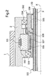
figure 2 est une demi-vue partielle en coupe schématique d'un actionneur selon un mode particulier de réalisation de l'invention. Les références des pièces communes avec celles de lafigure 1 ont été gardées. - L'actionneur de l'invention illustré à la
figure 2 est essentiellement similaire à l'actionneur de l'art antérieur illustré à lafigure 1 . - Il dispose toujours d'un corps 1 dans lequel une tige principale 2 est montée à coulissement télescopique. Une tige auxiliaire 20 est montée à coulissement dans la tige principale 2 d'un filetage extérieur 101 sur la tige auxiliaire 20. En outre, et bien que cela ne soit pas visible ici, il dispose des mêmes moyens commandés de retenue 30,31,32,33 de la tige auxiliaire 20 en position rentrée dans la tige principale 2, qui ne sont donc pas redécrits ici.
- La différence réside dans la façon dont la tige auxiliaire 20 est guidée dans la tige principale 2 et dans la façon dont la tige auxiliaire 20 est freinée vis-à-vis de la tige principale 2 lorsque la tige auxiliaire 20 est libérée.
- Plus précisément, la tige auxiliaire 20 comporte un filetage 101 sa surface externe. La tige principale 2 reçoit à son extrémité un palier 102 qui est monté tournant sur la tige principale 2 au moyen de roulements 103,104. Le palier tournant 102 est relié à la tige auxiliaire 20 par une liaison hélicoïdale réversible au moyen de rouleaux satellites filetés 105 qui s'étendent entre la tige auxiliaire 20 et le palier tournant 102 de sorte qu'une extension de la tige auxiliaire 20 provoque une rotation du palier tournant 102.
- Ainsi, l'actionneur de l'invention comporte un palier tournant qui est disposé en extrémité de la tige principale 2 et qui centre la tige auxiliaire 20 dans la tige principale 2. L'extrémité de la tige auxiliaire 20 qui s'étend dans la tige principale 2 porte quant à elle un palier lisse (non visible ici) qui coulisse dans la tige principale, dont la paroi intérieure est maintenant lisse. Par rapport à la disposition de l'art antérieur illustré à la
figure 1 , les paliers sont inversés : le palier tournant 102 est maintenant disposé en extrémité de tige principale 2 et ne se déplace plus avec la tige auxiliaire 20, tandis que le palier lisse est maintenant disposé en extrémité de tige auxiliaire 20 et se déplace donc avec la tige auxiliaire 20. - L'actionneur de l'invention comporte des moyens de freinage de la tige auxiliaire 20, qui agissent sur le palier tournant 102 pour freiner sa rotation. Plus précisément, les moyens de freinage comportent :
- un rotor 106 disposé sur le palier tournant 102 pour tourner avec ce dernier. Le rotor 106 est ici en fer pur et reçoit des aimants permanents 107 disposés à la périphérie du rotor 106. En variante, le rotor 106 pourra être réalisé en acier magnétique. On remarquera que le palier tournant 102 est en deux parties 108,109, la partie 108 qui porte le rotor 106 étant réalisée en matériau non magnétique, par exemple en acier inoxydable amagnétique ;
- un stator 110, porté par la tige principale 2 et bloqué en rotation par une clavette 111. Le stator est réalisé en matériau conducteur non magnétique.
- Le rotor 106 et le stator 110 sont en interaction magnétique de sorte que lorsque le palier tournant 102 et donc la rotor 106 tourne, un couple électromagnétique résistant s'établit qui tend à freiner la rotation du palier tournant 102, et donc la sortie de la tige auxiliaire 20. Ce moyen de freinage magnétique est purement passif et exerce sur la tige auxiliaire 20 un effort de freinage proportionnel à la vitesse de rotation du palier tournant 102, et donc à la vitesse de sortie de la tige auxiliaire 20.
- Les moyens de freinage agissent ainsi directement sur l'élément (le palier tournant) en liaison hélicoïdale avec la tige auxiliaire 20.
- L'invention n'est pas limitée à ce qui vient d'être décrit, mais bien au contraire englobe toute variante entrant dans le cadre défini par les revendications.
- En particulier, bien que les moyens de freinage soient ici de type purement magnétique, on pourra employer d'autres moyens de freinage, comme par exemple des moyens de freinage à frottement.
Claims (4)
- Actionneur télescopique comportant un corps (1) dans lequel une tige principale (2) est montée pour coulisser télescopiquement selon un axe de coulissement (X) entre une position rentrée et une position sortie, l'actionneur télescopique comportant une tige auxiliaire montée pour coulisser télescopiquement dans la tige principale selon le dit axe de coulissement entre une position rentrée et une position sortie, l'actionneur comportant des moyens commandés de retenue (30,31,32,33) de la tige auxiliaire en position rentrée dans la tige principale, l'actionneur comportant en outre des moyens de freinage d'un coulissement de la tige auxiliaire dans la tige principale dans le sens d'une extension, caractérisée en ce que la tige auxiliaire (20) comporte un filetage (101) sur une surface externe, la tige principale (2) portant à son extrémité un palier tournant (102) qui centre la tige auxiliaire dans la tige principale et qui coopère par une liaison hélicoïdale réversible avec le filetage de la tige auxiliaire de sorte qu'une sortie de la tige auxiliaire provoque une rotation du palier tournant, les moyens de freinage (106,110) étant agencés pour freiner une rotation du palier tournant lors d'une extension de la tige auxiliaire.
- Actionneur selon la revendication 1, dans lequel la liaison hélicoïdale réversible entre la tige auxiliaire (20) et le palier tournant (102) comporte des rouleaux satellites filetés (105).
- Actionneur selon la revendication 1, dans lequel les moyens de freinage comprennent un rotor (106) porté par le palier tournant (102), et un stator (110) porté par la tige principale (2), le stator et le rotor étant en interaction magnétique pour générer un couple résistant lorsque le palier tournant (102) tourne.
- Actionneur selon la revendication 3, dans lequel le rotor (106) porte des aimants permanents (107), et le stator (107) est en matériau conducteur non magnétique.
Applications Claiming Priority (1)
| Application Number | Priority Date | Filing Date | Title |
|---|---|---|---|
| FR0802198A FR2930308B1 (fr) | 2008-04-21 | 2008-04-21 | Actionneur a tige principale et tige auxiliare. |
Publications (2)
| Publication Number | Publication Date |
|---|---|
| EP2112402A1 true EP2112402A1 (fr) | 2009-10-28 |
| EP2112402B1 EP2112402B1 (fr) | 2011-11-02 |
Family
ID=40040088
Family Applications (1)
| Application Number | Title | Priority Date | Filing Date |
|---|---|---|---|
| EP09290261A Active EP2112402B1 (fr) | 2008-04-21 | 2009-04-09 | Actionneur à tige principale et tige auxiliaire |
Country Status (10)
| Country | Link |
|---|---|
| US (1) | US8286520B2 (fr) |
| EP (1) | EP2112402B1 (fr) |
| JP (1) | JP4856211B2 (fr) |
| CN (1) | CN101581354B (fr) |
| AT (1) | ATE531973T1 (fr) |
| AU (1) | AU2009201474B2 (fr) |
| BR (1) | BRPI0900918A2 (fr) |
| CA (1) | CA2664721C (fr) |
| ES (1) | ES2375540T3 (fr) |
| FR (1) | FR2930308B1 (fr) |
Cited By (2)
| Publication number | Priority date | Publication date | Assignee | Title |
|---|---|---|---|---|
| WO2016008541A1 (fr) * | 2014-07-18 | 2016-01-21 | Aktiebolaget Skf | Dispositif d'actionnement à doubles moyens de raccordement à vis |
| CN111409100A (zh) * | 2020-04-16 | 2020-07-14 | 广东博智林机器人有限公司 | 伸缩机构、机械臂及建筑机器人 |
Families Citing this family (7)
| Publication number | Priority date | Publication date | Assignee | Title |
|---|---|---|---|---|
| US8960031B2 (en) * | 2009-09-01 | 2015-02-24 | Parker-Hannifin Corporation | Aircraft stabilizer actuator |
| FR2976040B1 (fr) * | 2011-06-06 | 2015-05-22 | Messier Bugatti Dowty | Actionneur telescopique. |
| EA020935B1 (ru) * | 2012-05-11 | 2015-02-27 | Зао "Диаконт" | Электромеханический привод с демпфирующим устройством |
| DE102014221090A1 (de) * | 2013-11-18 | 2015-05-21 | Schaeffler Technologies Gmbh & Co. Kg | Planetenwälzgetriebe und Aktor mit diesem |
| US9906094B2 (en) * | 2015-03-20 | 2018-02-27 | American Axle & Manufacturing, Inc. | Direct drive actuator with switched reluctance motor |
| US10711871B2 (en) | 2018-01-26 | 2020-07-14 | Schaeffler Technologies AG & Co. KG | Axially compact linear actuator drive arrangement |
| EP3670336B1 (fr) * | 2018-12-20 | 2020-09-23 | Safran Landing Systems UK Limited | Train d'atterrissage d'aéronef et ensemble de réglage de pas |
Citations (3)
| Publication number | Priority date | Publication date | Assignee | Title |
|---|---|---|---|---|
| GB2272205A (en) * | 1992-11-06 | 1994-05-11 | Grumman Aerospace Corp | Differential linear actuator |
| US20060113933A1 (en) * | 2004-06-04 | 2006-06-01 | The Boeing Company | Fault-tolerant electromechanical actuator having a torque sensing control system |
| FR2895483A1 (fr) | 2005-12-23 | 2007-06-29 | Messier Bugatti Sa | Actionneur telescopique a tige principale et tige auxiliaire, et procede faisant application |
Family Cites Families (8)
| Publication number | Priority date | Publication date | Assignee | Title |
|---|---|---|---|---|
| FR951949A (fr) * | 1947-08-09 | 1949-11-07 | Auxiliaire Ind L | Vérin à vis, à moteur réversible, et sortie de secours de la tige |
| JP2847899B2 (ja) * | 1990-05-18 | 1999-01-20 | 日立工機株式会社 | ドットラインプリンタの印字ヘッド |
| GB9911148D0 (en) * | 1999-05-14 | 1999-07-14 | Lucas Ind Plc | Actuator |
| JP4008157B2 (ja) * | 1999-07-08 | 2007-11-14 | 美和ロック株式会社 | 引戸の緩衝装置 |
| EP1472477B1 (fr) * | 2002-01-25 | 2005-11-16 | Novo Nordisk A/S | Actionneur lineaire et dispositif distributeur medical comprenant un tel actionneur |
| JP2003301912A (ja) * | 2002-04-11 | 2003-10-24 | Mitsuba Corp | アクチュエータ |
| US6791215B2 (en) * | 2002-06-05 | 2004-09-14 | Board Of Regents The University Of Texas System | Fault tolerant linear actuator |
| US7190096B2 (en) * | 2004-06-04 | 2007-03-13 | The Boeing Company | Fault-tolerant electro-mechanical actuator having motor armatures to drive a ram and having an armature release mechanism |
-
2008
- 2008-04-21 FR FR0802198A patent/FR2930308B1/fr active Active
-
2009
- 2009-04-09 ES ES09290261T patent/ES2375540T3/es active Active
- 2009-04-09 EP EP09290261A patent/EP2112402B1/fr active Active
- 2009-04-09 AT AT09290261T patent/ATE531973T1/de active
- 2009-04-15 CA CA2664721A patent/CA2664721C/fr active Active
- 2009-04-15 AU AU2009201474A patent/AU2009201474B2/en not_active Ceased
- 2009-04-16 US US12/424,997 patent/US8286520B2/en active Active
- 2009-04-17 BR BRPI0900918-3A patent/BRPI0900918A2/pt not_active IP Right Cessation
- 2009-04-20 JP JP2009101910A patent/JP4856211B2/ja not_active Expired - Fee Related
- 2009-04-20 CN CN200910149715.2A patent/CN101581354B/zh active Active
Patent Citations (3)
| Publication number | Priority date | Publication date | Assignee | Title |
|---|---|---|---|---|
| GB2272205A (en) * | 1992-11-06 | 1994-05-11 | Grumman Aerospace Corp | Differential linear actuator |
| US20060113933A1 (en) * | 2004-06-04 | 2006-06-01 | The Boeing Company | Fault-tolerant electromechanical actuator having a torque sensing control system |
| FR2895483A1 (fr) | 2005-12-23 | 2007-06-29 | Messier Bugatti Sa | Actionneur telescopique a tige principale et tige auxiliaire, et procede faisant application |
Cited By (4)
| Publication number | Priority date | Publication date | Assignee | Title |
|---|---|---|---|---|
| WO2016008541A1 (fr) * | 2014-07-18 | 2016-01-21 | Aktiebolaget Skf | Dispositif d'actionnement à doubles moyens de raccordement à vis |
| US10378622B2 (en) | 2014-07-18 | 2019-08-13 | Aktiebolaget Skf | Actuating device with double screw connecting means |
| CN111409100A (zh) * | 2020-04-16 | 2020-07-14 | 广东博智林机器人有限公司 | 伸缩机构、机械臂及建筑机器人 |
| CN111409100B (zh) * | 2020-04-16 | 2021-09-07 | 广东博智林机器人有限公司 | 伸缩机构、机械臂及建筑机器人 |
Also Published As
| Publication number | Publication date |
|---|---|
| EP2112402B1 (fr) | 2011-11-02 |
| AU2009201474B2 (en) | 2013-06-06 |
| AU2009201474A1 (en) | 2009-11-05 |
| JP4856211B2 (ja) | 2012-01-18 |
| FR2930308B1 (fr) | 2010-06-04 |
| CN101581354B (zh) | 2012-01-11 |
| FR2930308A1 (fr) | 2009-10-23 |
| BRPI0900918A2 (pt) | 2010-01-26 |
| ATE531973T1 (de) | 2011-11-15 |
| CA2664721A1 (fr) | 2009-10-21 |
| CN101581354A (zh) | 2009-11-18 |
| US20090260462A1 (en) | 2009-10-22 |
| CA2664721C (fr) | 2010-10-19 |
| JP2009264589A (ja) | 2009-11-12 |
| US8286520B2 (en) | 2012-10-16 |
| ES2375540T3 (es) | 2012-03-01 |
Similar Documents
| Publication | Publication Date | Title |
|---|---|---|
| EP2112402B1 (fr) | Actionneur à tige principale et tige auxiliaire | |
| EP1801007B1 (fr) | Actionneur télescopique à tige principale et tige auxiliaire, et procédé faisant application | |
| EP2864167B1 (fr) | Servofrein electrique a compensation de jeu de transmission | |
| EP2944521B1 (fr) | Actionneur électromécanique de frein à blocage de parc pour aéronef | |
| EP1845016A1 (fr) | Atterrisseur comportant plusieurs actionneurs électromécaniques d'orientation | |
| FR2560922A1 (fr) | Dispositif pour empecher l'application d'une tension excessive au moteur a ressort d'un store de fenetre | |
| CH652462A5 (fr) | Actuateur lineaire a moteur electrique. | |
| WO2017174477A1 (fr) | Etrier de frein electromagnetique comprenant un guidage de piston a frottements reduits | |
| FR3024516A1 (fr) | Reducteur de couple | |
| FR2642813A1 (fr) | Moyen d'entrainement a moteur electrique pour un organe de manoeuvre | |
| EP1587205B1 (fr) | Vérin d'actionnement à capteur associé à sa tige | |
| EP2168867B1 (fr) | Actionneur télescopique à tige principale et à tige auxiliaire | |
| FR3039458A1 (fr) | Moyeu pour roue de cycle | |
| FR2937607A1 (fr) | Reducteur de vitesse a vis sans fin et roue tangente | |
| FR2894731A1 (fr) | Machine electrique tournante comportant un frein venant en prise avec au moins une surface de freinage s'etendant non entierement perpendiculairement a l'axe de rotation | |
| EP0775798B1 (fr) | Dispositif d'entraínement en rotation d'un élément d'enroulement de volet roulant | |
| EP1610026B1 (fr) | Etrier de frein à disque électromécanique | |
| EP2039968B1 (fr) | Dispositif de commande à moyens d'étanchéité perfectionnés | |
| EP2565104B1 (fr) | Système de direction à crémaillère pour véhicule automobile | |
| FR2749362A1 (fr) | Perfectionnement aux compresseurs de ressorts | |
| EP2824366B1 (fr) | Moteur électrique | |
| BE516475A (fr) | ||
| FR2873170A1 (fr) | Demarreur, notamment de vehicule automobile, equipe d'un lanceur a roue libre par friction | |
| FR2745348A3 (fr) | Dispositif d'embrayage ameliore, destine a l'embrayage et au debrayage de deux arbres | |
| EP2037143B1 (fr) | Dispositif de commande perfectionné |
Legal Events
| Date | Code | Title | Description |
|---|---|---|---|
| PUAI | Public reference made under article 153(3) epc to a published international application that has entered the european phase |
Free format text: ORIGINAL CODE: 0009012 |
|
| AK | Designated contracting states |
Kind code of ref document: A1 Designated state(s): AT BE BG CH CY CZ DE DK EE ES FI FR GB GR HR HU IE IS IT LI LT LU LV MC MK MT NL NO PL PT RO SE SI SK TR |
|
| 17P | Request for examination filed |
Effective date: 20100326 |
|
| GRAP | Despatch of communication of intention to grant a patent |
Free format text: ORIGINAL CODE: EPIDOSNIGR1 |
|
| RAP1 | Party data changed (applicant data changed or rights of an application transferred) |
Owner name: MESSIER-BUGATTI-DOWTY |
|
| GRAS | Grant fee paid |
Free format text: ORIGINAL CODE: EPIDOSNIGR3 |
|
| GRAA | (expected) grant |
Free format text: ORIGINAL CODE: 0009210 |
|
| AK | Designated contracting states |
Kind code of ref document: B1 Designated state(s): AT BE BG CH CY CZ DE DK EE ES FI FR GB GR HR HU IE IS IT LI LT LU LV MC MK MT NL NO PL PT RO SE SI SK TR |
|
| REG | Reference to a national code |
Ref country code: GB Ref legal event code: FG4D Free format text: NOT ENGLISH |
|
| REG | Reference to a national code |
Ref country code: CH Ref legal event code: EP |
|
| REG | Reference to a national code |
Ref country code: IE Ref legal event code: FG4D |
|
| REG | Reference to a national code |
Ref country code: DE Ref legal event code: R096 Ref document number: 602009003420 Country of ref document: DE Effective date: 20120126 |
|
| REG | Reference to a national code |
Ref country code: NL Ref legal event code: VDEP Effective date: 20111102 |
|
| REG | Reference to a national code |
Ref country code: ES Ref legal event code: FG2A Ref document number: 2375540 Country of ref document: ES Kind code of ref document: T3 Effective date: 20120301 |
|
| LTIE | Lt: invalidation of european patent or patent extension |
Effective date: 20111102 |
|
| PG25 | Lapsed in a contracting state [announced via postgrant information from national office to epo] |
Ref country code: IS Free format text: LAPSE BECAUSE OF FAILURE TO SUBMIT A TRANSLATION OF THE DESCRIPTION OR TO PAY THE FEE WITHIN THE PRESCRIBED TIME-LIMIT Effective date: 20120302 Ref country code: LT Free format text: LAPSE BECAUSE OF FAILURE TO SUBMIT A TRANSLATION OF THE DESCRIPTION OR TO PAY THE FEE WITHIN THE PRESCRIBED TIME-LIMIT Effective date: 20111102 Ref country code: NO Free format text: LAPSE BECAUSE OF FAILURE TO SUBMIT A TRANSLATION OF THE DESCRIPTION OR TO PAY THE FEE WITHIN THE PRESCRIBED TIME-LIMIT Effective date: 20120202 |
|
| PG25 | Lapsed in a contracting state [announced via postgrant information from national office to epo] |
Ref country code: PL Free format text: LAPSE BECAUSE OF FAILURE TO SUBMIT A TRANSLATION OF THE DESCRIPTION OR TO PAY THE FEE WITHIN THE PRESCRIBED TIME-LIMIT Effective date: 20111102 Ref country code: SI Free format text: LAPSE BECAUSE OF FAILURE TO SUBMIT A TRANSLATION OF THE DESCRIPTION OR TO PAY THE FEE WITHIN THE PRESCRIBED TIME-LIMIT Effective date: 20111102 Ref country code: PT Free format text: LAPSE BECAUSE OF FAILURE TO SUBMIT A TRANSLATION OF THE DESCRIPTION OR TO PAY THE FEE WITHIN THE PRESCRIBED TIME-LIMIT Effective date: 20120302 Ref country code: HR Free format text: LAPSE BECAUSE OF FAILURE TO SUBMIT A TRANSLATION OF THE DESCRIPTION OR TO PAY THE FEE WITHIN THE PRESCRIBED TIME-LIMIT Effective date: 20111102 Ref country code: SE Free format text: LAPSE BECAUSE OF FAILURE TO SUBMIT A TRANSLATION OF THE DESCRIPTION OR TO PAY THE FEE WITHIN THE PRESCRIBED TIME-LIMIT Effective date: 20111102 Ref country code: LV Free format text: LAPSE BECAUSE OF FAILURE TO SUBMIT A TRANSLATION OF THE DESCRIPTION OR TO PAY THE FEE WITHIN THE PRESCRIBED TIME-LIMIT Effective date: 20111102 Ref country code: GR Free format text: LAPSE BECAUSE OF FAILURE TO SUBMIT A TRANSLATION OF THE DESCRIPTION OR TO PAY THE FEE WITHIN THE PRESCRIBED TIME-LIMIT Effective date: 20120203 Ref country code: NL Free format text: LAPSE BECAUSE OF FAILURE TO SUBMIT A TRANSLATION OF THE DESCRIPTION OR TO PAY THE FEE WITHIN THE PRESCRIBED TIME-LIMIT Effective date: 20111102 |
|
| REG | Reference to a national code |
Ref country code: IE Ref legal event code: FD4D |
|
| PG25 | Lapsed in a contracting state [announced via postgrant information from national office to epo] |
Ref country code: CY Free format text: LAPSE BECAUSE OF FAILURE TO SUBMIT A TRANSLATION OF THE DESCRIPTION OR TO PAY THE FEE WITHIN THE PRESCRIBED TIME-LIMIT Effective date: 20111102 |
|
| PG25 | Lapsed in a contracting state [announced via postgrant information from national office to epo] |
Ref country code: DK Free format text: LAPSE BECAUSE OF FAILURE TO SUBMIT A TRANSLATION OF THE DESCRIPTION OR TO PAY THE FEE WITHIN THE PRESCRIBED TIME-LIMIT Effective date: 20111102 Ref country code: CZ Free format text: LAPSE BECAUSE OF FAILURE TO SUBMIT A TRANSLATION OF THE DESCRIPTION OR TO PAY THE FEE WITHIN THE PRESCRIBED TIME-LIMIT Effective date: 20111102 Ref country code: IE Free format text: LAPSE BECAUSE OF FAILURE TO SUBMIT A TRANSLATION OF THE DESCRIPTION OR TO PAY THE FEE WITHIN THE PRESCRIBED TIME-LIMIT Effective date: 20111102 Ref country code: BG Free format text: LAPSE BECAUSE OF FAILURE TO SUBMIT A TRANSLATION OF THE DESCRIPTION OR TO PAY THE FEE WITHIN THE PRESCRIBED TIME-LIMIT Effective date: 20120202 Ref country code: SK Free format text: LAPSE BECAUSE OF FAILURE TO SUBMIT A TRANSLATION OF THE DESCRIPTION OR TO PAY THE FEE WITHIN THE PRESCRIBED TIME-LIMIT Effective date: 20111102 Ref country code: EE Free format text: LAPSE BECAUSE OF FAILURE TO SUBMIT A TRANSLATION OF THE DESCRIPTION OR TO PAY THE FEE WITHIN THE PRESCRIBED TIME-LIMIT Effective date: 20111102 |
|
| PG25 | Lapsed in a contracting state [announced via postgrant information from national office to epo] |
Ref country code: RO Free format text: LAPSE BECAUSE OF FAILURE TO SUBMIT A TRANSLATION OF THE DESCRIPTION OR TO PAY THE FEE WITHIN THE PRESCRIBED TIME-LIMIT Effective date: 20111102 |
|
| PLBE | No opposition filed within time limit |
Free format text: ORIGINAL CODE: 0009261 |
|
| STAA | Information on the status of an ep patent application or granted ep patent |
Free format text: STATUS: NO OPPOSITION FILED WITHIN TIME LIMIT |
|
| REG | Reference to a national code |
Ref country code: AT Ref legal event code: MK05 Ref document number: 531973 Country of ref document: AT Kind code of ref document: T Effective date: 20111102 |
|
| 26N | No opposition filed |
Effective date: 20120803 |
|
| BERE | Be: lapsed |
Owner name: MESSIER-BUGATTI-DOWTY Effective date: 20120430 |
|
| REG | Reference to a national code |
Ref country code: DE Ref legal event code: R097 Ref document number: 602009003420 Country of ref document: DE Effective date: 20120803 |
|
| PG25 | Lapsed in a contracting state [announced via postgrant information from national office to epo] |
Ref country code: MC Free format text: LAPSE BECAUSE OF NON-PAYMENT OF DUE FEES Effective date: 20120430 |
|
| PG25 | Lapsed in a contracting state [announced via postgrant information from national office to epo] |
Ref country code: BE Free format text: LAPSE BECAUSE OF NON-PAYMENT OF DUE FEES Effective date: 20120430 Ref country code: AT Free format text: LAPSE BECAUSE OF FAILURE TO SUBMIT A TRANSLATION OF THE DESCRIPTION OR TO PAY THE FEE WITHIN THE PRESCRIBED TIME-LIMIT Effective date: 20111102 |
|
| PG25 | Lapsed in a contracting state [announced via postgrant information from national office to epo] |
Ref country code: MK Free format text: LAPSE BECAUSE OF FAILURE TO SUBMIT A TRANSLATION OF THE DESCRIPTION OR TO PAY THE FEE WITHIN THE PRESCRIBED TIME-LIMIT Effective date: 20111102 |
|
| PG25 | Lapsed in a contracting state [announced via postgrant information from national office to epo] |
Ref country code: FI Free format text: LAPSE BECAUSE OF FAILURE TO SUBMIT A TRANSLATION OF THE DESCRIPTION OR TO PAY THE FEE WITHIN THE PRESCRIBED TIME-LIMIT Effective date: 20111102 |
|
| PG25 | Lapsed in a contracting state [announced via postgrant information from national office to epo] |
Ref country code: MT Free format text: LAPSE BECAUSE OF FAILURE TO SUBMIT A TRANSLATION OF THE DESCRIPTION OR TO PAY THE FEE WITHIN THE PRESCRIBED TIME-LIMIT Effective date: 20111102 |
|
| PGFP | Annual fee paid to national office [announced via postgrant information from national office to epo] |
Ref country code: IT Payment date: 20130419 Year of fee payment: 5 |
|
| REG | Reference to a national code |
Ref country code: CH Ref legal event code: PL |
|
| PG25 | Lapsed in a contracting state [announced via postgrant information from national office to epo] |
Ref country code: LI Free format text: LAPSE BECAUSE OF NON-PAYMENT OF DUE FEES Effective date: 20130430 Ref country code: CH Free format text: LAPSE BECAUSE OF NON-PAYMENT OF DUE FEES Effective date: 20130430 |
|
| PG25 | Lapsed in a contracting state [announced via postgrant information from national office to epo] |
Ref country code: TR Free format text: LAPSE BECAUSE OF FAILURE TO SUBMIT A TRANSLATION OF THE DESCRIPTION OR TO PAY THE FEE WITHIN THE PRESCRIBED TIME-LIMIT Effective date: 20111102 |
|
| PG25 | Lapsed in a contracting state [announced via postgrant information from national office to epo] |
Ref country code: LU Free format text: LAPSE BECAUSE OF NON-PAYMENT OF DUE FEES Effective date: 20120409 |
|
| PG25 | Lapsed in a contracting state [announced via postgrant information from national office to epo] |
Ref country code: HU Free format text: LAPSE BECAUSE OF FAILURE TO SUBMIT A TRANSLATION OF THE DESCRIPTION OR TO PAY THE FEE WITHIN THE PRESCRIBED TIME-LIMIT Effective date: 20090409 |
|
| PGFP | Annual fee paid to national office [announced via postgrant information from national office to epo] |
Ref country code: ES Payment date: 20140428 Year of fee payment: 6 |
|
| PG25 | Lapsed in a contracting state [announced via postgrant information from national office to epo] |
Ref country code: IT Free format text: LAPSE BECAUSE OF NON-PAYMENT OF DUE FEES Effective date: 20140409 |
|
| REG | Reference to a national code |
Ref country code: DE Ref legal event code: R082 Ref document number: 602009003420 Country of ref document: DE Representative=s name: SCHAUMBURG & PARTNER PATENTANWAELTE GBR, DE Ref country code: DE Ref legal event code: R082 Ref document number: 602009003420 Country of ref document: DE Representative=s name: SCHAUMBURG UND PARTNER PATENTANWAELTE MBB, DE |
|
| REG | Reference to a national code |
Ref country code: FR Ref legal event code: PLFP Year of fee payment: 8 |
|
| REG | Reference to a national code |
Ref country code: ES Ref legal event code: FD2A Effective date: 20161230 |
|
| PG25 | Lapsed in a contracting state [announced via postgrant information from national office to epo] |
Ref country code: ES Free format text: LAPSE BECAUSE OF NON-PAYMENT OF DUE FEES Effective date: 20150410 |
|
| REG | Reference to a national code |
Ref country code: FR Ref legal event code: PLFP Year of fee payment: 9 |
|
| REG | Reference to a national code |
Ref country code: FR Ref legal event code: CD Owner name: MESSIER-BUGATTI-DOWTY, FR Effective date: 20170518 |
|
| REG | Reference to a national code |
Ref country code: FR Ref legal event code: PLFP Year of fee payment: 10 |
|
| PGFP | Annual fee paid to national office [announced via postgrant information from national office to epo] |
Ref country code: DE Payment date: 20250417 Year of fee payment: 17 |
|
| PGFP | Annual fee paid to national office [announced via postgrant information from national office to epo] |
Ref country code: FR Payment date: 20250422 Year of fee payment: 17 |
|
| PGFP | Annual fee paid to national office [announced via postgrant information from national office to epo] |
Ref country code: GB Payment date: 20260327 Year of fee payment: 18 |