EP2111996A2 - Stamp with swappable stamp insert - Google Patents
Stamp with swappable stamp insert Download PDFInfo
- Publication number
- EP2111996A2 EP2111996A2 EP09005612A EP09005612A EP2111996A2 EP 2111996 A2 EP2111996 A2 EP 2111996A2 EP 09005612 A EP09005612 A EP 09005612A EP 09005612 A EP09005612 A EP 09005612A EP 2111996 A2 EP2111996 A2 EP 2111996A2
- Authority
- EP
- European Patent Office
- Prior art keywords
- punch
- recess
- latching
- insert
- punch insert
- Prior art date
- Legal status (The legal status is an assumption and is not a legal conclusion. Google has not performed a legal analysis and makes no representation as to the accuracy of the status listed.)
- Granted
Links
Images

Classifications
-
- B—PERFORMING OPERATIONS; TRANSPORTING
- B41—PRINTING; LINING MACHINES; TYPEWRITERS; STAMPS
- B41K—STAMPS; STAMPING OR NUMBERING APPARATUS OR DEVICES
- B41K1/00—Portable hand-operated devices without means for supporting or locating the articles to be stamped, i.e. hand stamps; Inking devices or other accessories therefor
- B41K1/02—Portable hand-operated devices without means for supporting or locating the articles to be stamped, i.e. hand stamps; Inking devices or other accessories therefor with one or more flat stamping surfaces having fixed images
- B41K1/04—Portable hand-operated devices without means for supporting or locating the articles to be stamped, i.e. hand stamps; Inking devices or other accessories therefor with one or more flat stamping surfaces having fixed images with multiple stamping surfaces; with stamping surfaces replaceable as a whole
-
- B—PERFORMING OPERATIONS; TRANSPORTING
- B44—DECORATIVE ARTS
- B44B—MACHINES, APPARATUS OR TOOLS FOR ARTISTIC WORK, e.g. FOR SCULPTURING, GUILLOCHING, CARVING, BRANDING, INLAYING
- B44B5/00—Machines or apparatus for embossing decorations or marks, e.g. embossing coins
- B44B5/02—Dies; Accessories
- B44B5/026—Dies
Definitions
- the invention relates to a stamp with replaceable punch insert for attaching labels, contours or imprints on a variety of materials.
- the stamp insert generally has raised or recessed stamp markings on its surface in order to affix a lettering or embossing to the material to be stamped in the gravure or gravure printing method.
- the stamp insert can be moved in a known manner either relative to the material to be stamped, or the material is injected in an injection molding in an injection mold, wherein the punch insert with the stamp marks itself is part of the injection mold, so that on the manufactured with the injection mold plastic part on the surface of the desired stamp marking is attached.
- a punch with a punch insert in which the punch insert has a substantially semi-circular cross section, wherein on the outer circumference of the punch insert a latching projection and the plunger body a spring is provided which cooperates with the latching projection, thus the punch insert on the punch body easily and without additional To attach parts.
- a punch is described with a replaceable punch insert, wherein the punch insert has a latching projection, which is pivoted by a rotation in a recess of the plunger body and held by means of a spreading compound in installation target position, which disengages the expansion joint from the end position by force on the punch insert.
- the present invention seeks to provide a stamp of the type mentioned with a replaceable punch insert for attaching different labels, contours or embossing on a variety To provide materials that is easily and safely interchangeable and also held during handling in a further improved and secured position.
- the invention provides a punch with replaceable punch insert according to the features of claim 1.
- This stamp with replaceable punch insert for attaching labels, contours or embossing to a variety of materials is particularly characterized in that a latching projection of its punch insert has a detent recess, wherein in the installation position of the punch insert in the punch body of the punch to a stop in a further recess of the plunger body rests and in the arranged on the punch insert detent recess engages a movably guided locking body.
- the locking body is arranged in a further, a third recess of the punch body.
- This locking body is movably guided in the direction of the punch insert and is pressed by a recess provided in the punch body energy storage, preferably a spring element, in the direction of the punch insert that the punch insert is held captive and secured by the latching connection in an end position in installation target position in the punch body , Nevertheless, the latching connection can be released by this force acting on the punch insert, so that the out of the end position disengaging punch insert after a Back rotation can be removed from the semi-circular recess of the punch body.
- the latching connection consists of engaging in the detent recess of the interchangeable punch insert detent body, wherein the detent body is held in a detent position in the detent recess of the punch insert by the spring element fitting.
- the locking body is preferably formed as a cylindrical pin whose cylindrical surface in the detent position in the detent recess and on the side surfaces of the recess and on the spring element is applied and that the detent body in the recess movable is guided, wherein acting on the locking body by means of the spring element in the direction of the punch insert a steady pressure force.
- the spring element is formed in particular as a flat band steel spring and disposed in a recess provided in the punch body below the recess for the detent body recess, wherein the spring element bears against the detent body, and wherein the necessary movement of the spring element, the recess wider than the thickness of the spring element is.
- the spring element is held pressed in the recess and secured against lateral slipping.
- the punch insert is rotatable about a rotational axis counterclockwise when inserting the punch insert in the semicircular recess of the punch body, wherein the locking projection of the punch insert into the recess of the punch body pivoted into a stop in an end position and held captive in this end position by the latching connection.
- Spring element 9 abuts.
- the locking body 11 is movably guided in the third recess 14, wherein on the locking body 11 by means of the spring element 9 in the direction of the punch insert 4, a steady pressure force is exerted.
- the spring element 9 is formed in particular as a flat band steel spring and arranged in a provided in the punch body 2 below the third recess 14 recess 12, wherein the spring element 9 presses the locking body 11 in the locking recess 10 in the locking position.
- the spring element 9 is held in the recess 12 and secured against lateral slipping.
- the recess 12 is wider than the thickness of the spring element 9. Zur Holder of the punch body 2, a through hole 2, not shown, is provided for a retaining pin.
- the invention is not limited to the illustrated embodiment, but is often variable within the scope of the disclosure, in particular in the embodiment of Snap-in connection 10, 11.
- the stamp according to the invention can be used for attaching labels, contours or embossing to a variety of materials, preferably in the so-called gravure or gravure printing method, but its use is not limited to these methods.
Abstract
Description
Die Erfindung betrifft einen Stempel mit auswechselbarem Stempeleinsatz zum Anbringen von Beschriftungen, Konturen oder Prägungen an unterschiedlichsten Materialien.The invention relates to a stamp with replaceable punch insert for attaching labels, contours or imprints on a variety of materials.
Aus dem Stand der Technik sind dem Fachmann eine Vielzahl von Stempeln zum Anbringen einer Beschriftung oder Prägung in unterschiedlichste Materialien mit unterschiedlichsten Ausführungsformen bekannt. Der Stempeleinsatz weist dabei im Allgemeinen an seiner Oberfläche erhabene oder vertiefte Stempelmarkierungen auf, um auf das zu stempelnde Material im Hoch- oder Tiefdruckverfahren eine Beschriftung oder Prägung anzubringen. Der Stempeleinsatz kann dazu in bekannter Weise entweder relativ zu dem zu bestempelnden Material bewegt werden, oder das Material wird in einem Spritzgussvorgang in eine Spritzgussform eingespritzt, wobei der Stempeleinsatz mit den Stempelmarkierungen selbst Bestandteil der Spritzgussform ist, so dass an dem mit der Spritzgussform gefertigten Kunststoffteil an dessen Oberfläche die gewünschte Stempelmarkierung angebracht ist.From the prior art, a variety of punches for attaching a label or embossing in a variety of materials with various embodiments are known in the art. The stamp insert generally has raised or recessed stamp markings on its surface in order to affix a lettering or embossing to the material to be stamped in the gravure or gravure printing method. The stamp insert can be moved in a known manner either relative to the material to be stamped, or the material is injected in an injection molding in an injection mold, wherein the punch insert with the stamp marks itself is part of the injection mold, so that on the manufactured with the injection mold plastic part on the surface of the desired stamp marking is attached.
Es sind weiterhin lösbare Stempeleinsätze bekannt, um mit einem Stempel nacheinander durch Austausch des Stempeleinsatzes unterschiedliche Beschriftungen oder Prägungen an den Materialien anzubringen. Die Befestigung bekannter auswechselbarer Stempeleinsätze erfolgt dabei beispielsweise über aufwendige Verschraubungen, so dass das Austauschen der Stempeleinsätze oftmals mit einem erheblichen Zeitaufwand verbunden ist. Aus derThere are also releasable punch inserts known to attach with a stamp successively by replacing the punch insert different labels or imprints on the materials. The attachment of known interchangeable punch inserts is carried out, for example, by expensive screwing, so that the replacement of the punch inserts is often associated with a considerable amount of time. From the
Ausgehend von diesem Stand der Technik liegt der Erfindung die Aufgabe zugrunde, einen Stempel eingangs genannter Art mit einem auswechselbaren Stempeleinsatz zum Anbringen unterschiedlicher Beschriftungen, Konturen oder Prägungen an unterschiedlichsten Materialien zu schaffen, der auf einfache und sichere Weise auswechselbar ist und darüber hinaus während der Handhabung in einer weiter verbesserten und gesicherten Position gehalten ist.Based on this prior art, the present invention seeks to provide a stamp of the type mentioned with a replaceable punch insert for attaching different labels, contours or embossing on a variety To provide materials that is easily and safely interchangeable and also held during handling in a further improved and secured position.
Zur Lösung dieser Aufgabe sieht die Erfindung einen Stempel mit auswechselbarem Stempeleinsatz gemäß den Merkmalen des Anspruches 1 vor.
Dieser Stempel mit auswechselbarem Stempeleinsatz zum Anbringen von Beschriftungen, Konturen oder Prägungen an unterschiedlichsten Materialien zeichnet sich insbesondere dadurch aus, dass ein Rastvorsprung seines Stempeleinsatzes eine Rastmulde aufweist, wobei in der Einbausolllage der Stempeleinsatz in dem Stempelkörper des Stempels an einem Anschlag in einer weiterenAusnehmung des Stempelkörpers anliegt und in die am Stempeleinsatz angeordnete Rastmulde ein beweglich geführter Rastkörper eingreift.
Der Rastkörper ist in einer weiteren, einer dritten Ausnehmung des Stempelkörpers angeordnet. Dieser Rastkörper ist in Richtung des Stempeleinsatzes beweglich geführt und wird durch einen in einer Aussparung im Stempelkörper vorgesehenen Kraftspeicher, bevorzugt ein Federelement, derart in Richtung des Stempeleinsatzes gedrückt, dass der Stempeleinsatz in einer Endstellung in Einbausolllage im Stempelkörper unverlierbar und gesichert mittels der Rastverbindung gehalten ist. Gleichwohl ist durch diese Krafteinwirkung auf den Stempeleinsatz die Rastverbindung lösbar, so dass der aus der Endstellung wieder ausrastende Stempeleinsatz nach einer Zurückdrehung aus der halbrunden Ausnehmung des Stempelkörpers entnommen werden kann.
Eine vorteilhafte Ausführungsform wird darin zu gesehen, dass die Rastverbindung aus dem in die Rastmulde des auswechselbaren Stempeleinsatzes eingreifenden Rastkörper besteht, wobei der Rastkörper in einer Raststellung in der Rastmulde des Stempeleinsatzes durch das Federelement anliegend gehalten ist.
Eine bevorzugte sowohl fertigungstechnisch günstige als auch materialsparende Ausgestaltung wird darin gesehen, dass der Rastkörper vorzugsweise als zylindrischer Stift ausgebildet ist, dessen Zylinderfläche in der Raststellung in der Rastmulde sowie an den Seitenflächen der Ausnehmung und an dem Federelement anliegt und dass der Rastkörper in der Ausnehmung beweglich geführt ist, wobei auf den Rastkörper mittels des Federelementes in Richtung des Stempeleinsatzes eine stetige Druckkraft wirkt.To solve this problem, the invention provides a punch with replaceable punch insert according to the features of
This stamp with replaceable punch insert for attaching labels, contours or embossing to a variety of materials is particularly characterized in that a latching projection of its punch insert has a detent recess, wherein in the installation position of the punch insert in the punch body of the punch to a stop in a further recess of the plunger body rests and in the arranged on the punch insert detent recess engages a movably guided locking body.
The locking body is arranged in a further, a third recess of the punch body. This locking body is movably guided in the direction of the punch insert and is pressed by a recess provided in the punch body energy storage, preferably a spring element, in the direction of the punch insert that the punch insert is held captive and secured by the latching connection in an end position in installation target position in the punch body , Nevertheless, the latching connection can be released by this force acting on the punch insert, so that the out of the end position disengaging punch insert after a Back rotation can be removed from the semi-circular recess of the punch body.
An advantageous embodiment is seen in that the latching connection consists of engaging in the detent recess of the interchangeable punch insert detent body, wherein the detent body is held in a detent position in the detent recess of the punch insert by the spring element fitting.
A preferred both manufacturing technology favorable as well as material-saving design is seen in that the locking body is preferably formed as a cylindrical pin whose cylindrical surface in the detent position in the detent recess and on the side surfaces of the recess and on the spring element is applied and that the detent body in the recess movable is guided, wherein acting on the locking body by means of the spring element in the direction of the punch insert a steady pressure force.
Eine vorteilhafte Weiterbildung wird darin gesehen, dass das Federelement insbesondere als flache Bandstahlfeder ausgebildet und in einer im Stempelkörper unterhalb der Ausnehmung für den Rastkörper vorgesehenen Aussparung angeordnet ist, wobei das Federelement an dem Rastkörper anliegt, und wobei zur notwendigen Bewegung des Federelementes die Aussparung breiter als die Dicke des Federelementes ist. Dabei wird das Federelement in der Aussparung eingepresst gehalten und gegen seitliches Verrutschen gesichert.An advantageous development is seen in that the spring element is formed in particular as a flat band steel spring and disposed in a recess provided in the punch body below the recess for the detent body recess, wherein the spring element bears against the detent body, and wherein the necessary movement of the spring element, the recess wider than the thickness of the spring element is. The spring element is held pressed in the recess and secured against lateral slipping.
Dadurch, dass zum Einsetzen des Stempeleinsatzes in die halbrunde Ausnehmung des Stempelkörpers der Stempeleinsatz um eine Drehachse entgegen dem Uhrzeigersinn drehbar ist, wobei der Rastvorsprung des Stempeleinsatzes in die Ausnehmung des Stempelkörpers bis zu einem Anschlag in eine Endstellung hineinschwenkbar ist und in dieser Endstellung durch die Rastverbindung gehalten ist und dadurch, dass zum Entfernen des Stempeleinsatzes aus dem Stempelkörper manuell eine Kraft auf den Stempeleinsatz ausgeübt wird, wobei der Rastkörper aus der Rastmulde ausrastet, und wobei der Stempeleinsatz um seine Drehachse im Uhrzeigersinn so weit drehbar ist, bis der Rastvorsprung des Stempeleinsatzes nicht mehr in die Ausnehmung des Stempelkörpers hineinragt und der Stempeleinsatz aus dem Stempelkörper dann entnehmbar ist, wird eine einfache, sichere und schnelle Ein- sowie Ausrastung des Stempeleinsatzes im Stempelkörper gewährleistet.Characterized in that for insertion of the punch insert in the semicircular recess of the punch body of the punch insert is rotatable about an axis of rotation counterclockwise, wherein the latching projection of the punch insert into the recess of the punch body is hineinschwenkbar up to a stop in an end position and in this end position by the latching connection is held and in that for removing the punch insert from the punch body manually a force is exerted on the punch insert, wherein the latching body disengages from the latching recess, and wherein the punch insert is rotatable about its axis of rotation in the clockwise direction until the latching projection of the punch insert not more protrudes into the recess of the punch body and the punch insert is then removed from the punch body, a simple, safe and fast engagement and disengagement of the punch insert is ensured in the punch body.
Durch diese Art der Ausbildung des Stempeleinsatzes und der Rastverbindung ist der Stempeleinsatz in einer Position sicher und einfach in dem Stempelkörper während der Handhabung des Stempels gehalten. Durch Ausführung einer Drehbewegung und der einseitigen Krafteinwirkung auf den Stempeleinsatz durch einen Benutzer, bei der sich der Stempeleinsatz in der halbrunden Ausnehmung des Stempelkörpers definiert verdreht und aus der Rastverbindung ausrastet, kann der Stempeleinsatz ohne zusätzliches Werkzeug zum Auswechseln einfach herausgedreht und dann entnommen werden. Neben der einfachen Fertigung und Montage des Stempels mit dem auswechselbaren Stempel wird eine schnelle Auswechselbarkeit gewährleistet, indem beim Einsetzen des Stempeleinsatzes in die halbrunde Ausnehmung des Stempelkörpers der Stempeleinsatz um eine Drehachse entgegen dem Uhrzeigersinn drehbar ist, wobei der Rastvorsprung des Stempeleinsatzes in die Ausnehmung des Stempelkörpers bis zu einem Anschlag in eine Endstellung hineinschwenkbar und in dieser Endstellung durch die Rastverbindung unverlierbar gehalten ist.By this type of training of the punch insert and the latching connection of the punch insert is held in a position safe and easy in the punch body during handling of the punch. By performing a rotational movement and the unilateral force acting on the punch insert by a user in which the punch insert rotates defined in the semicircular recess of the punch body and out of the latching connection snaps out, the punch insert can be easily removed without additional tools for replacement and then removed. In addition to the simple production and assembly of the punch with the replaceable punch quick replaceability is ensured by the punch insert is rotatable about a rotational axis counterclockwise when inserting the punch insert in the semicircular recess of the punch body, wherein the locking projection of the punch insert into the recess of the punch body pivoted into a stop in an end position and held captive in this end position by the latching connection.
Die Erfindung wird nachfolgend anhand eines schematisch in Zeichnungen dargestellten Ausführungsbeispieles näher erläutert. Es zeigt:
- Fig.1
- einen erfindungsgemäßen Stempel in Vorderansicht;
- Fig.2
- den Stempel nach
Figur 1 - Fig.3
- den Stempel nach
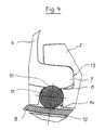
Figur 1 - Fig.4
- eine Detailansicht zu den Elementen der Rastverbindung.
Gemäß den
In
- Fig.1
- a stamp according to the invention in front view;
- Fig.2
- the stamp after
FIG. 1 , with pivoted punch insert; - Figure 3
- the stamp after
FIG. 1 , with engaged punch body and - Figure 4
- a detailed view of the elements of the locking connection.
According to the
In
Federelement 9 anliegt. Der Rastkörper 11 ist dabei in der dritten Ausnehmung 14 beweglich geführt, wobei auf den Rastkörper 11 mittels des Federelementes 9 in Richtung des Stempeleinsatzes 4 eine stetige Druckkraft ausgeübt wird. Das Federelement 9 ist insbesondere als flache Bandstahlfeder ausgebildet und in einer im Stempelkörper 2 unterhalb der dritten Ausnehmung 14 vorgesehenen Aussparung 12 angeordnet, wobei das Federelement 9 in der Raststellung den Rastkörper 11 in die Rastmulde 10 presst. Das Federelement 9 ist in der Aussparung 12 gehalten und gegen seitliches Verrutschen gesichert. Zur notwendigen Bewegung des Federelementes 9 ist die Aussparung 12 breiter als die Dicke des Federelementes 9. Zur Halterung des Stempelkörpers 2 ist eine nicht näher dargestellte Durchgangsbohrung 2 für einen Haltestift vorgesehen.
Zum Entfernen des Stempeleinsatzes 4 aus dem Stempelkörper 2 wird manuell eine Kraft auf den Stempeleinsatz 4 ausgeübt, wobei der Rastkörper 11 aus der Rastmulde 10 ausrastet und der Stempeleinsatz 4 um seine Drehachse im Uhrzeigersinn so weit drehbar ist, bis der Rastvorsprung 7 des Stempeleinsatzes 4 nicht mehr in die weitere Ausnehmung 8 des Stempelkörpers 2 hineinragt und der Stempeleinsatz 4 aus dem Stempelkörper 2 entnehmbar ist.
To remove the
Die Erfindung beschränkt sich nicht auf das dargestellte Ausführungsbeispiel, sondern ist im Rahmen der Offenbarung vielfach variabel, insbesondere in der Ausgestaltung der
Rastverbindung 10, 11. Der erfindungsgemäße Stempel ist zum Anbringen von Beschriftungen, Konturen oder Prägungen an unterschiedlichsten Materialien vorzugsweise im so genannten Hoch- oder Tiefdruckverfahren einsetzbar, jedoch ist sein Einsatz nicht auf diese Verfahren beschränkt.The invention is not limited to the illustrated embodiment, but is often variable within the scope of the disclosure, in particular in the embodiment of
Snap-in
- 11
- Stempelstamp
- 22
- Stempelkörperstamp body
- 33
- Durchgangsbohrung für HaltestiftThrough hole for retaining pin
- 3'3 '
- Haltestiftretaining pin
- 44
- Stempeleinsatzpunch insert
- 4'4 '
- Fläche mit Stempelmarkierungen (an Pos.4)Area with stamp markings (at pos.4)
- 55
- halbrunde Ausnehmung des Stempelkörperssemicircular recess of the punch body
- 66
- halbrunder Außenumfang des Stempeleinsatzessemicircular outer circumference of the punch insert
- 77
- Rastvorsprungcatch projection
- 88th
- weitere (zweite) Ausnehmungfurther (second) recess
- 99
- Federelementspring element
- 1010
- Rastmuldecatch recess
- 1111
- Rastkörperlatching body
- 1212
- Aussparungrecess
- 1313
- Anschlagattack
- 1414
- dritte Ausnehmungthird recess
Claims (9)
dadurch gekennzeichnet,
dass der Rastvorsprung (7) des Stempeleinsatzes (4) eine
Rastmulde (10) aufweist, wobei in der Einbausolllage der Stempeleinsatz (4) in dem Stempelkörper (2) an einem Anschlag (13) in der weiteren Ausnehmung (8) des Stempelkörpers (2) anliegt und in die am Stempeleinsatz (4) angeordnete Rastmulde (10) ein beweglich geführter Rastkörper (11) eingreift.A punch with replaceable punch insert for attaching labels, contours or embossments to a wide variety of materials, comprising a punch body (2) having a substantially semicircular recess (5) into which a punch marks (4 ') exhibiting punch insert (4) can be inserted, the punch insert (4) has a catch projection (7) on its half-round outer circumference (6), which is pivotable into a further recess (8) of the punch body (2) and held in a built-in desired position in the punch body (2) with a latching connection,
characterized,
that the latching projection (7) of the punch insert (4) has a
Detent recess (10), wherein in the installation position of the punch insert (4) in the punch body (2) against a stop (13) in the further recess (8) of the punch body (2) and in the on the punch insert (4) arranged detent recess (10) engages a movably guided locking body (11).
dadurch gekennzeichnet,
dass der Rastkörper (11) in einer dritten Ausnehmung (14) des Stempelkörpers (2) angeordnet ist, wobei die bewegliche Führung des Rastkörpers (11) in Richtung des Stempeleinsatzes (4) ausgerichtet ist und durch einen in einer Aussparung (12) im Stempelkörper (2) vorgesehenen Kraftspeicher derart in Richtung des
Stempeleinsatzes (4) gedrückt wird, dass der Stempeleinsatz (4) in einer Endstellung in Einbausolllage im Stempelkörper (2) unverlierbar und gesichert mittels der Rastverbindung (10, 11) gehalten ist, und wobei durch eine Krafteinwirkung auf den Stempeleinsatz (4) die Rastverbindung (10, 11) lösbar und der Stempeleinsatz (4) aus der Endstellung wieder ausrastend nach einer Zurückdrehung aus der halbrunden Ausnehmung (5) des Stempelkörpers (2) zu entnehmen ist.A stamp according to claim 1,
characterized,
in that the latching body (11) is arranged in a third recess (14) of the plunger body (2), wherein the movable guide of the latching body (11) is aligned in the direction of the punch insert (4) and through a recess (12) in the plunger body (2) provided energy storage in the direction of
Stamp insert (4) is pressed, that the punch insert (4) is held captive and secured by means of the latching connection (10, 11) in an end position in installation target position in the punch body (2), and wherein by a force on the punch insert (4) the latching connection (10, 11) releasably and the punch insert (4) from the end position again ausrastend after a reverse rotation of the semicircular recess (5) of the punch body (2) can be seen.
dadurch gekennzeichnet,
dass die Rastverbindung aus dem in die Rastmulde (10) des auswechselbaren Stempeleinsatzes (4) eingreifenden Rastkörper (11) besteht, wobei der Rastkörper (11) in einer Raststellung in der Rastmulde (10) des Stempeleinsatzes (4) durch ein Federelement (9) anliegend gehalten ist.A stamp according to claim 2,
characterized,
in that the latching connection (11) engages in the latching recess (10) of the replaceable punch insert (4), wherein the latching member (11) is locked in a latching position in the latching recess (10) of the punch insert (4) by a spring element (9). attached.
dadurch gekennzeichnet,
dass der Rastkörper (11) vorzugsweise als zylindrischer Stift ausgebildet ist, dessen Zylinderfläche in der Raststellung in der Rastmulde (10) und an den Seitenflächen der Ausnehmung (14) sowie an dem Federelement (9) anliegt.A stamp according to claim 1, 2 or 3,
characterized,
in that the latching body (11) is preferably designed as a cylindrical pin, the cylindrical surface of which rests in the latching position in the latching recess (10) and on the side surfaces of the recess (14) and on the spring element (9).
dadurch gekennzeichnet,
dass der Rastkörper (11) in der Ausnehmung (14) beweglich so geführt ist, dass auf den Rastkörper (11) mittels des Federelementes (9) in Richtung des Stempeleinsatzes (4) eine stetige Druckkraft wirkt.A stamp according to one of claims 2, 3 or 4,
characterized,
in that the latching body (11) is movably guided in the recess (14) such that a continuous pressure force acts on the latching body (11) by means of the spring element (9) in the direction of the punch insert (4).
dadurch gekennzeichnet,
dass das Federelement (9) insbesondere als flache Bandstahlfeder ausgebildet und in einer im Stempelkörper (2) unterhalb der Ausnehmung (14) für den Rastkörper (11) vorgesehenen
Aussparung (12) angeordnet ist, wobei das Federelement (9) an dem Rastkörper (11) anliegt, und wobei zur notwendigen Bewegung des Federelementes (9) die Aussparung (12) breiter als die Dicke des Federelementes (9) ist.A stamp according to any one of claims 3, 4 or 5,
characterized,
in that the spring element (9) is designed, in particular, as a flat band steel spring and provided in a stamp body (2) below the recess (14) for the latching body (11)
Recess (12) is arranged, wherein the spring element (9) on the detent body (11) is present, and wherein the necessary movement of the spring element (9), the recess (12) is wider than the thickness of the spring element (9).
dadurch gekennzeichnet,
dass das Federelement (9) in der Aussparung (12) gehalten und gegen seitliches Verrutschen gesichert ist.A stamp according to any one of claims 3, 4, 5 or 6,
characterized,
that the spring element (9) is held in the recess (12) and secured against lateral slippage.
dadurch gekennzeichnet,
dass zum Einsetzen des Stempeleinsatzes (4) in die halbrunde Ausnehmung (5) des Stempelkörpers (2) der Stempeleinsatz (4) um eine Drehachse entgegen dem Uhrzeigersinn drehbar ist, wobei der Rastvorsprung (7) des Stempeleinsatzes (4) in die Ausnehmung (8) des Stempelkörpers (2) bis zu einem Anschlag (13) in eine Endstellung hineinschwenkbar ist und in dieser Endstellung durch die Rastverbindung (10, 11) gehalten ist.A stamp according to any one of claims 1 to 7,
characterized,
in that the stamping insert (4) is rotatable about an axis of rotation counterclockwise for insertion of the punch insert (4) into the semicircular recess (5) of the punch body (2), the latching projection (7) of the punch insert (4) being inserted into the recess (8 ) of the plunger body (2) can be pivoted into an end position up to a stop (13) and held in this end position by the latching connection (10, 11).
dadurch gekennzeichnet,
dass zum Entfernen des Stempeleinsatzes (4) aus dem
Stempelkörper (2) manuell eine Kraft auf den Stempeleinsatz (4) ausgeübt wird, wobei der Rastkörper (11) aus der Rastmulde (10) ausrastet, und der Stempeleinsatz (4) um seine Drehachse im Uhrzeigersinn so weit drehbar ist, bis der Rastvorsprung (7) des Stempeleinsatzes (4) nicht mehr in die Ausnehmung (8) des Stempelkörpers (2) hineinragt und der Stempeleinsatz (4) aus dem Stempelkörper (2) entnehmbar ist.
characterized,
that for removing the punch insert (4) from the
Piston body (2) is manually exerted a force on the punch insert (4), wherein the latching body (11) from the latching recess (10) disengages, and the punch insert (4) is rotatable about its axis of rotation in the clockwise direction until the latching projection ( 7) of the punch insert (4) no longer protrudes into the recess (8) of the punch body (2) and the punch insert (4) from the punch body (2) can be removed.
Applications Claiming Priority (1)
| Application Number | Priority Date | Filing Date | Title |
|---|---|---|---|
| DE200820005762 DE202008005762U1 (en) | 2008-04-25 | 2008-04-25 | Stamp with replaceable punch insert |
Publications (3)
| Publication Number | Publication Date |
|---|---|
| EP2111996A2 true EP2111996A2 (en) | 2009-10-28 |
| EP2111996A3 EP2111996A3 (en) | 2011-05-25 |
| EP2111996B1 EP2111996B1 (en) | 2013-02-20 |
Family
ID=39587838
Family Applications (1)
| Application Number | Title | Priority Date | Filing Date |
|---|---|---|---|
| EP20090005612 Active EP2111996B1 (en) | 2008-04-25 | 2009-04-22 | Stamp with swappable stamp insert |
Country Status (2)
| Country | Link |
|---|---|
| EP (1) | EP2111996B1 (en) |
| DE (1) | DE202008005762U1 (en) |
Citations (2)
| Publication number | Priority date | Publication date | Assignee | Title |
|---|---|---|---|---|
| DE20307129U1 (en) | 2003-04-27 | 2003-08-14 | Ziegler Sven | stamp |
| DE202007005512U1 (en) | 2007-04-05 | 2007-07-12 | Ziegler, Sven | Stamp with exchangeable insert, comprises extension engaging with recess and v-shaped spring |
Family Cites Families (1)
| Publication number | Priority date | Publication date | Assignee | Title |
|---|---|---|---|---|
| US5778774A (en) * | 1996-12-18 | 1998-07-14 | Framatome Connectors Usa Inc. | Articulating embossing die |
-
2008
- 2008-04-25 DE DE200820005762 patent/DE202008005762U1/en not_active Expired - Lifetime
-
2009
- 2009-04-22 EP EP20090005612 patent/EP2111996B1/en active Active
Patent Citations (2)
| Publication number | Priority date | Publication date | Assignee | Title |
|---|---|---|---|---|
| DE20307129U1 (en) | 2003-04-27 | 2003-08-14 | Ziegler Sven | stamp |
| DE202007005512U1 (en) | 2007-04-05 | 2007-07-12 | Ziegler, Sven | Stamp with exchangeable insert, comprises extension engaging with recess and v-shaped spring |
Also Published As
| Publication number | Publication date |
|---|---|
| EP2111996B1 (en) | 2013-02-20 |
| DE202008005762U1 (en) | 2008-07-03 |
| EP2111996A3 (en) | 2011-05-25 |
Similar Documents
| Publication | Publication Date | Title |
|---|---|---|
| EP3307545B1 (en) | Stamp | |
| EP3307546B1 (en) | Stamp, ink pad and a closure cap | |
| EP3235074B1 (en) | Crimping pliers | |
| EP3307548B1 (en) | Stamp and printing unit, in particular as replacement part for a stamp | |
| EP2005042B1 (en) | Inflatable sealing device for a die | |
| DE102009027108B3 (en) | identification stamp | |
| DE102014112878A1 (en) | Torque wrench with a locking device | |
| AT514078A4 (en) | bending tool | |
| DE1929875A1 (en) | Interchangeable identification stamp in - injection mould wall | |
| EP2111996B1 (en) | Stamp with swappable stamp insert | |
| DE3243970A1 (en) | POCKET STAMP | |
| DE1475784C3 (en) | Unmistakable connection coupling and tools for their adjustment | |
| DE60301051T2 (en) | Universal marking insert for injection molding tools | |
| EP1473169A2 (en) | Exchangeable stamping pad | |
| AT524047B1 (en) | Stamp and axis element for the stamp | |
| DE202005013126U1 (en) | Connector device for fluid line, has combined holding and releasing ring supporting claw components and designed such that it compresses piece for releasing fluid line, where removal of components is resulted by releasing line | |
| AT520674A1 (en) | Portable stamp | |
| DE202007005512U1 (en) | Stamp with exchangeable insert, comprises extension engaging with recess and v-shaped spring | |
| DE102013106287A1 (en) | Device for producing at least one undercut in a slotted or closed sheet metal profile | |
| DE3129843C2 (en) | Measuring tape with a fitting for inside and outside measurements | |
| DE102010036796B4 (en) | Provided with a control ball coupling | |
| DE102005025587B3 (en) | injection molding | |
| AT8752U1 (en) | WRITE, PAINT OR DRAWING | |
| DE2214709C3 (en) | Fountain pen with a plug connection between the front part and the barrel | |
| EP2099103B1 (en) | Crimping tool |
Legal Events
| Date | Code | Title | Description |
|---|---|---|---|
| PUAI | Public reference made under article 153(3) epc to a published international application that has entered the european phase |
Free format text: ORIGINAL CODE: 0009012 |
|
| AK | Designated contracting states |
Kind code of ref document: A2 Designated state(s): AT BE BG CH CY CZ DE DK EE ES FI FR GB GR HR HU IE IS IT LI LT LU LV MC MK MT NL NO PL PT RO SE SI SK TR |
|
| PUAL | Search report despatched |
Free format text: ORIGINAL CODE: 0009013 |
|
| AK | Designated contracting states |
Kind code of ref document: A3 Designated state(s): AT BE BG CH CY CZ DE DK EE ES FI FR GB GR HR HU IE IS IT LI LT LU LV MC MK MT NL NO PL PT RO SE SI SK TR |
|
| AX | Request for extension of the european patent |
Extension state: AL BA RS |
|
| 17P | Request for examination filed |
Effective date: 20111125 |
|
| 17Q | First examination report despatched |
Effective date: 20120123 |
|
| RIC1 | Information provided on ipc code assigned before grant |
Ipc: B41K 1/04 20060101AFI20120814BHEP Ipc: B44B 5/02 20060101ALI20120814BHEP |
|
| GRAP | Despatch of communication of intention to grant a patent |
Free format text: ORIGINAL CODE: EPIDOSNIGR1 |
|
| GRAS | Grant fee paid |
Free format text: ORIGINAL CODE: EPIDOSNIGR3 |
|
| GRAA | (expected) grant |
Free format text: ORIGINAL CODE: 0009210 |
|
| AK | Designated contracting states |
Kind code of ref document: B1 Designated state(s): AT BE BG CH CY CZ DE DK EE ES FI FR GB GR HR HU IE IS IT LI LT LU LV MC MK MT NL NO PL PT RO SE SI SK TR |
|
| REG | Reference to a national code |
Ref country code: GB Ref legal event code: FG4D Free format text: NOT ENGLISH |
|
| REG | Reference to a national code |
Ref country code: CH Ref legal event code: EP |
|
| REG | Reference to a national code |
Ref country code: AT Ref legal event code: REF Ref document number: 597364 Country of ref document: AT Kind code of ref document: T Effective date: 20130315 |
|
| REG | Reference to a national code |
Ref country code: IE Ref legal event code: FG4D Free format text: LANGUAGE OF EP DOCUMENT: GERMAN |
|
| REG | Reference to a national code |
Ref country code: CH Ref legal event code: NV Representative=s name: ROTTMANN, ZIMMERMANN + PARTNER AG, CH |
|
| REG | Reference to a national code |
Ref country code: DE Ref legal event code: R096 Ref document number: 502009006260 Country of ref document: DE Effective date: 20130418 |
|
| REG | Reference to a national code |
Ref country code: NL Ref legal event code: VDEP Effective date: 20130220 |
|
| REG | Reference to a national code |
Ref country code: LT Ref legal event code: MG4D |
|
| PG25 | Lapsed in a contracting state [announced via postgrant information from national office to epo] |
Ref country code: NO Free format text: LAPSE BECAUSE OF FAILURE TO SUBMIT A TRANSLATION OF THE DESCRIPTION OR TO PAY THE FEE WITHIN THE PRESCRIBED TIME-LIMIT Effective date: 20130520 Ref country code: LT Free format text: LAPSE BECAUSE OF FAILURE TO SUBMIT A TRANSLATION OF THE DESCRIPTION OR TO PAY THE FEE WITHIN THE PRESCRIBED TIME-LIMIT Effective date: 20130220 Ref country code: SE Free format text: LAPSE BECAUSE OF FAILURE TO SUBMIT A TRANSLATION OF THE DESCRIPTION OR TO PAY THE FEE WITHIN THE PRESCRIBED TIME-LIMIT Effective date: 20130220 Ref country code: ES Free format text: LAPSE BECAUSE OF FAILURE TO SUBMIT A TRANSLATION OF THE DESCRIPTION OR TO PAY THE FEE WITHIN THE PRESCRIBED TIME-LIMIT Effective date: 20130531 Ref country code: BG Free format text: LAPSE BECAUSE OF FAILURE TO SUBMIT A TRANSLATION OF THE DESCRIPTION OR TO PAY THE FEE WITHIN THE PRESCRIBED TIME-LIMIT Effective date: 20130520 Ref country code: IS Free format text: LAPSE BECAUSE OF FAILURE TO SUBMIT A TRANSLATION OF THE DESCRIPTION OR TO PAY THE FEE WITHIN THE PRESCRIBED TIME-LIMIT Effective date: 20130620 |
|
| PG25 | Lapsed in a contracting state [announced via postgrant information from national office to epo] |
Ref country code: FI Free format text: LAPSE BECAUSE OF FAILURE TO SUBMIT A TRANSLATION OF THE DESCRIPTION OR TO PAY THE FEE WITHIN THE PRESCRIBED TIME-LIMIT Effective date: 20130220 Ref country code: GR Free format text: LAPSE BECAUSE OF FAILURE TO SUBMIT A TRANSLATION OF THE DESCRIPTION OR TO PAY THE FEE WITHIN THE PRESCRIBED TIME-LIMIT Effective date: 20130521 Ref country code: LV Free format text: LAPSE BECAUSE OF FAILURE TO SUBMIT A TRANSLATION OF THE DESCRIPTION OR TO PAY THE FEE WITHIN THE PRESCRIBED TIME-LIMIT Effective date: 20130220 Ref country code: PL Free format text: LAPSE BECAUSE OF FAILURE TO SUBMIT A TRANSLATION OF THE DESCRIPTION OR TO PAY THE FEE WITHIN THE PRESCRIBED TIME-LIMIT Effective date: 20130220 Ref country code: SI Free format text: LAPSE BECAUSE OF FAILURE TO SUBMIT A TRANSLATION OF THE DESCRIPTION OR TO PAY THE FEE WITHIN THE PRESCRIBED TIME-LIMIT Effective date: 20130220 Ref country code: PT Free format text: LAPSE BECAUSE OF FAILURE TO SUBMIT A TRANSLATION OF THE DESCRIPTION OR TO PAY THE FEE WITHIN THE PRESCRIBED TIME-LIMIT Effective date: 20130620 |
|
| PG25 | Lapsed in a contracting state [announced via postgrant information from national office to epo] |
Ref country code: HR Free format text: LAPSE BECAUSE OF FAILURE TO SUBMIT A TRANSLATION OF THE DESCRIPTION OR TO PAY THE FEE WITHIN THE PRESCRIBED TIME-LIMIT Effective date: 20130220 |
|
| BERE | Be: lapsed |
Owner name: ZIEGLER, SVEN Effective date: 20130430 |
|
| PG25 | Lapsed in a contracting state [announced via postgrant information from national office to epo] |
Ref country code: DK Free format text: LAPSE BECAUSE OF FAILURE TO SUBMIT A TRANSLATION OF THE DESCRIPTION OR TO PAY THE FEE WITHIN THE PRESCRIBED TIME-LIMIT Effective date: 20130220 Ref country code: SK Free format text: LAPSE BECAUSE OF FAILURE TO SUBMIT A TRANSLATION OF THE DESCRIPTION OR TO PAY THE FEE WITHIN THE PRESCRIBED TIME-LIMIT Effective date: 20130220 Ref country code: RO Free format text: LAPSE BECAUSE OF FAILURE TO SUBMIT A TRANSLATION OF THE DESCRIPTION OR TO PAY THE FEE WITHIN THE PRESCRIBED TIME-LIMIT Effective date: 20130220 Ref country code: EE Free format text: LAPSE BECAUSE OF FAILURE TO SUBMIT A TRANSLATION OF THE DESCRIPTION OR TO PAY THE FEE WITHIN THE PRESCRIBED TIME-LIMIT Effective date: 20130220 Ref country code: NL Free format text: LAPSE BECAUSE OF FAILURE TO SUBMIT A TRANSLATION OF THE DESCRIPTION OR TO PAY THE FEE WITHIN THE PRESCRIBED TIME-LIMIT Effective date: 20130220 Ref country code: CZ Free format text: LAPSE BECAUSE OF FAILURE TO SUBMIT A TRANSLATION OF THE DESCRIPTION OR TO PAY THE FEE WITHIN THE PRESCRIBED TIME-LIMIT Effective date: 20130220 |
|
| PG25 | Lapsed in a contracting state [announced via postgrant information from national office to epo] |
Ref country code: MC Free format text: LAPSE BECAUSE OF FAILURE TO SUBMIT A TRANSLATION OF THE DESCRIPTION OR TO PAY THE FEE WITHIN THE PRESCRIBED TIME-LIMIT Effective date: 20130220 Ref country code: CY Free format text: LAPSE BECAUSE OF FAILURE TO SUBMIT A TRANSLATION OF THE DESCRIPTION OR TO PAY THE FEE WITHIN THE PRESCRIBED TIME-LIMIT Effective date: 20130220 |
|
| PLBE | No opposition filed within time limit |
Free format text: ORIGINAL CODE: 0009261 |
|
| STAA | Information on the status of an ep patent application or granted ep patent |
Free format text: STATUS: NO OPPOSITION FILED WITHIN TIME LIMIT |
|
| PG25 | Lapsed in a contracting state [announced via postgrant information from national office to epo] |
Ref country code: IT Free format text: LAPSE BECAUSE OF FAILURE TO SUBMIT A TRANSLATION OF THE DESCRIPTION OR TO PAY THE FEE WITHIN THE PRESCRIBED TIME-LIMIT Effective date: 20130220 |
|
| 26N | No opposition filed |
Effective date: 20131121 |
|
| GBPC | Gb: european patent ceased through non-payment of renewal fee |
Effective date: 20130520 |
|
| REG | Reference to a national code |
Ref country code: IE Ref legal event code: MM4A |
|
| PG25 | Lapsed in a contracting state [announced via postgrant information from national office to epo] |
Ref country code: BE Free format text: LAPSE BECAUSE OF NON-PAYMENT OF DUE FEES Effective date: 20130430 |
|
| REG | Reference to a national code |
Ref country code: FR Ref legal event code: ST Effective date: 20131231 |
|
| PG25 | Lapsed in a contracting state [announced via postgrant information from national office to epo] |
Ref country code: FR Free format text: LAPSE BECAUSE OF NON-PAYMENT OF DUE FEES Effective date: 20130430 |
|
| REG | Reference to a national code |
Ref country code: DE Ref legal event code: R097 Ref document number: 502009006260 Country of ref document: DE Effective date: 20131121 |
|
| PG25 | Lapsed in a contracting state [announced via postgrant information from national office to epo] |
Ref country code: IE Free format text: LAPSE BECAUSE OF NON-PAYMENT OF DUE FEES Effective date: 20130422 Ref country code: GB Free format text: LAPSE BECAUSE OF NON-PAYMENT OF DUE FEES Effective date: 20130520 |
|
| PG25 | Lapsed in a contracting state [announced via postgrant information from national office to epo] |
Ref country code: MT Free format text: LAPSE BECAUSE OF FAILURE TO SUBMIT A TRANSLATION OF THE DESCRIPTION OR TO PAY THE FEE WITHIN THE PRESCRIBED TIME-LIMIT Effective date: 20130220 |
|
| REG | Reference to a national code |
Ref country code: DE Ref legal event code: R082 Ref document number: 502009006260 Country of ref document: DE Representative=s name: KANZLEI "REGION GOEPPINGEN" (GBR) PATENTANWALT, DE Ref country code: DE Ref legal event code: R082 Ref document number: 502009006260 Country of ref document: DE Representative=s name: FUERST, SIEGFRIED, DIPL.-ING., DE |
|
| PG25 | Lapsed in a contracting state [announced via postgrant information from national office to epo] |
Ref country code: TR Free format text: LAPSE BECAUSE OF FAILURE TO SUBMIT A TRANSLATION OF THE DESCRIPTION OR TO PAY THE FEE WITHIN THE PRESCRIBED TIME-LIMIT Effective date: 20130220 |
|
| PG25 | Lapsed in a contracting state [announced via postgrant information from national office to epo] |
Ref country code: MK Free format text: LAPSE BECAUSE OF FAILURE TO SUBMIT A TRANSLATION OF THE DESCRIPTION OR TO PAY THE FEE WITHIN THE PRESCRIBED TIME-LIMIT Effective date: 20130220 Ref country code: LU Free format text: LAPSE BECAUSE OF NON-PAYMENT OF DUE FEES Effective date: 20130422 Ref country code: HU Free format text: LAPSE BECAUSE OF FAILURE TO SUBMIT A TRANSLATION OF THE DESCRIPTION OR TO PAY THE FEE WITHIN THE PRESCRIBED TIME-LIMIT; INVALID AB INITIO Effective date: 20090422 |
|
| REG | Reference to a national code |
Ref country code: CH Ref legal event code: PCAR Free format text: NEW ADDRESS: GARTENSTRASSE 28 A, 5400 BADEN (CH) |
|
| REG | Reference to a national code |
Ref country code: DE Ref legal event code: R082 Ref document number: 502009006260 Country of ref document: DE Representative=s name: FUERST, SIEGFRIED, DIPL.-ING., DE |
|
| PGFP | Annual fee paid to national office [announced via postgrant information from national office to epo] |
Ref country code: CH Payment date: 20190328 Year of fee payment: 11 |
|
| REG | Reference to a national code |
Ref country code: CH Ref legal event code: PL |
|
| PG25 | Lapsed in a contracting state [announced via postgrant information from national office to epo] |
Ref country code: CH Free format text: LAPSE BECAUSE OF NON-PAYMENT OF DUE FEES Effective date: 20200430 Ref country code: LI Free format text: LAPSE BECAUSE OF NON-PAYMENT OF DUE FEES Effective date: 20200430 |
|
| PGFP | Annual fee paid to national office [announced via postgrant information from national office to epo] |
Ref country code: DE Payment date: 20230421 Year of fee payment: 15 |
|
| PGFP | Annual fee paid to national office [announced via postgrant information from national office to epo] |
Ref country code: AT Payment date: 20230403 Year of fee payment: 15 |