EP2111784A2 - Bending portion of medical insertion apparatus, and manufacturing method and manufacturing apparatus thereof - Google Patents
Bending portion of medical insertion apparatus, and manufacturing method and manufacturing apparatus thereof Download PDFInfo
- Publication number
- EP2111784A2 EP2111784A2 EP09156320A EP09156320A EP2111784A2 EP 2111784 A2 EP2111784 A2 EP 2111784A2 EP 09156320 A EP09156320 A EP 09156320A EP 09156320 A EP09156320 A EP 09156320A EP 2111784 A2 EP2111784 A2 EP 2111784A2
- Authority
- EP
- European Patent Office
- Prior art keywords
- bending
- instrument
- tube
- limiting
- manufacturing
- Prior art date
- Legal status (The legal status is an assumption and is not a legal conclusion. Google has not performed a legal analysis and makes no representation as to the accuracy of the status listed.)
- Withdrawn
Links
Images


Classifications
-
- A—HUMAN NECESSITIES
- A61—MEDICAL OR VETERINARY SCIENCE; HYGIENE
- A61B—DIAGNOSIS; SURGERY; IDENTIFICATION
- A61B1/00—Instruments for performing medical examinations of the interior of cavities or tubes of the body by visual or photographical inspection, e.g. endoscopes; Illuminating arrangements therefor
- A61B1/005—Flexible endoscopes
- A61B1/0051—Flexible endoscopes with controlled bending of insertion part
- A61B1/0055—Constructional details of insertion parts, e.g. vertebral elements
-
- A—HUMAN NECESSITIES
- A61—MEDICAL OR VETERINARY SCIENCE; HYGIENE
- A61B—DIAGNOSIS; SURGERY; IDENTIFICATION
- A61B1/00—Instruments for performing medical examinations of the interior of cavities or tubes of the body by visual or photographical inspection, e.g. endoscopes; Illuminating arrangements therefor
- A61B1/00064—Constructional details of the endoscope body
- A61B1/00071—Insertion part of the endoscope body
-
- A—HUMAN NECESSITIES
- A61—MEDICAL OR VETERINARY SCIENCE; HYGIENE
- A61B—DIAGNOSIS; SURGERY; IDENTIFICATION
- A61B1/00—Instruments for performing medical examinations of the interior of cavities or tubes of the body by visual or photographical inspection, e.g. endoscopes; Illuminating arrangements therefor
- A61B1/00064—Constructional details of the endoscope body
- A61B1/0011—Manufacturing of endoscope parts
-
- Y—GENERAL TAGGING OF NEW TECHNOLOGICAL DEVELOPMENTS; GENERAL TAGGING OF CROSS-SECTIONAL TECHNOLOGIES SPANNING OVER SEVERAL SECTIONS OF THE IPC; TECHNICAL SUBJECTS COVERED BY FORMER USPC CROSS-REFERENCE ART COLLECTIONS [XRACs] AND DIGESTS
- Y10—TECHNICAL SUBJECTS COVERED BY FORMER USPC
- Y10T—TECHNICAL SUBJECTS COVERED BY FORMER US CLASSIFICATION
- Y10T156/00—Adhesive bonding and miscellaneous chemical manufacture
- Y10T156/10—Methods of surface bonding and/or assembly therefor
- Y10T156/1052—Methods of surface bonding and/or assembly therefor with cutting, punching, tearing or severing
- Y10T156/1084—Methods of surface bonding and/or assembly therefor with cutting, punching, tearing or severing of continuous or running length bonded web
Landscapes
- Health & Medical Sciences (AREA)
- Life Sciences & Earth Sciences (AREA)
- Surgery (AREA)
- Engineering & Computer Science (AREA)
- Biomedical Technology (AREA)
- Molecular Biology (AREA)
- Pathology (AREA)
- Radiology & Medical Imaging (AREA)
- Nuclear Medicine, Radiotherapy & Molecular Imaging (AREA)
- Biophysics (AREA)
- Physics & Mathematics (AREA)
- Heart & Thoracic Surgery (AREA)
- Medical Informatics (AREA)
- Optics & Photonics (AREA)
- Animal Behavior & Ethology (AREA)
- General Health & Medical Sciences (AREA)
- Public Health (AREA)
- Veterinary Medicine (AREA)
- Manufacturing & Machinery (AREA)
- Endoscopes (AREA)
- Shaping Of Tube Ends By Bending Or Straightening (AREA)
- Instruments For Viewing The Inside Of Hollow Bodies (AREA)
Abstract

Description
- The present invention relates to a bending portion of a medical insertion apparatus configured to be inserted into the interior of the body, and a manufacturing method and a manufacturing apparatus thereof.
- Various medical insertion apparatuses configured to be inserted into the interior of the body has been used.
- As such a medical insertion apparatus, there are an endoscope and an overtube for an endoscope for improving an insertion performance of the endoscope into the interior of the body.
- In the endoscope and the overtube, an operation portion is connected to the proximal end portion of an elongate insertion portion, and the insertion portion is configured to be inserted into the interior of the body and the operation portion is configured to be held and operated by an operator. A bending portion is provided in the distal end portion of the insertion portion and configured to be actuated to be bent. The bending portion includes a bending tube forming a framework of the bending portion. The bending tube is formed of circularly cylindrical bending parts coaxially connected to each other and rotatable with respect to each other. The outer peripheral portion of the bending tube is covered with a braid tube. The braid tube is formed of strands made of metal or resin and braided into a circularly tubular shape. Both the end portions of the braid tube are fixed to both the end bending parts, respectively. The outer peripheral portion of the braid tube is covered with an outer tube.
- Jpn. Pat. Appln. KOKAI Publication No.
11-206701 - When a braid tube is fixed to a bending part using soldering or by adhesive as is disclosed in Jpn. Pat. Appln. KOKAI Publication No.
11-206701 - The present invention has been made in view of the above-mentioned problem, and is directed to providing a manufacturing method for a bending portion of a medical insertion apparatus wherein it is facilitated to fix a braid tube to a bending part, a bending portion of a medical insertion apparatus appropriate to be manufactured using the manufacturing method, and a manufacturing apparatus for a bending portion of a medical insertion apparatus appropriate to carry out the manufacturing method.
- In an aspect of the present invention, a manufacturing method for a bending portion of a medical insertion apparatus is characterized by comprising; preparing a bending tube including cylindrical bending parts coaxially connected to each other and rotatable with respect to each other; preparing a braid tube including liner members made of a thermoplastic resin and forming a netlike shape; covering the braid tube on an outer peripheral portion of the bending tube; pushing-heating of protruding inwardly a part of the braid tube to be pushed into a push-in receiving portion of the bending part, and heating the part to soften; and pushing-cooling of cooling the part to set.
- In the manufacturing method for the bending portion of the medical insertion apparatus according to the present aspect, the braid tube is fixed to the bending part just by protruding inwardly the part of the braid tube to be pushed into the push-in receiving portion of the bending part and heating the part to soften, and then cooling the part to set. Therefore, it is facilitated to fix the braid tube to the bending part.
- In another aspect of the present invention, a bending portion of a medical insertion apparatus is characterized by comprising: a bending tube including cylindrical bending parts coaxially connected to each other and rotatable with respect to each other; and a braid tube covering an outer peripheral portion of the bending tube, and including liner members made of a thermoplastic resin and forming a netlike shape, and wherein the braid tube includes a push-in portion formed of a part of the braid tube and protruding inwardly and the bending tube includes a push-in receiving portion provided with the bending part and in which the push-in portion is pushed.
- The bending portion of the medical insertion apparatus according to the present aspect is appropriate to be manufactured using the above manufacturing method for the bending portion of the medical insertion apparatus.
- In a preferred aspect of the present invention, a manufacturing apparatus for a bending portion of a medical insertion apparatus, wherein the bending portion includes: a bending tube including cylindrical bending parts coaxially connected to each other and rotatable with respect to each other; and a braid tube covering an outer peripheral portion of the bending tube, and including liner members made of a thermoplastic resin and forming a netlike shape, is
characterized by comprising: a pushing-in instrument configured to protrude inwardly a part of the braid tube to be pushed into a push-in receiving portion of the bending part; and a pushing-in instrument heating mechanism configured to heat the pushing-in instrument. - The manufacturing apparatus for the bending portion of the medical insertion apparatus according to the present aspect is appropriate to carry out the above manufacturing method for the bending portion of the medical insertion apparatus.
- In a preferred aspect of the present invention, the manufacturing apparatus for the bending portion of the medical insertion apparatus is characterized by further comprising a pushing-in instrument cooling mechanism configured to cool the pushing-in instrument.
- The manufacturing apparatus for the bending portion of the medical insertion apparatus according to the present aspect is further appropriate to carry out the above manufacturing method for the bending portion of the medical insertion apparatus.
- In a preferred aspect of the present invention, a manufacturing method for the bending portion of the medical insertion apparatus is characterized by further comprising: limiting-heating of limiting an outer diameter of the braid tube so as to be substantially equal to an outer diameter of the bending part in a region of the braid tube and heating the region to soften; and limitin-cooling of cooling the region to set.
- In the manufacturing method for the bending portion of the medical insertion apparatus according to the present aspect, it is facilitated to form the limited portion whose outer diameter is limited so as to be substantially equal to the outer diameter of the bending part.
- In a preferred aspect of the present invention, the bending portion of the medical insertion apparatus is characterized in that the braid tube includes a limited portion whose outer diameter of the limited portion is limited so as to be substantially equal to an outer diameter of the bending part.
- The bending portion of the medical insertion apparatus according to the present aspect is appropriate to be manufactured using the above manufacturing method for the bending portion of the medical insertion apparatus.
- In a preferred aspect of the present invention, the manufacturing apparatus for the bending portion of the medical insertion apparatus is characterized by further comprising: a limiting instrument configured to limit an outer diameter of the braid tube so as to be substantially equal to an outer diameter of the bending part in a region of the braid tube; and a limiting instrument heating mechanism configured to heat the limiting instrument.
- The manufacturing apparatus for the bending portion of the medical insertion apparatus according to the present aspect is appropriate to carry out the above manufacturing method for the bending portion of the medical insertion apparatus.
- In a preferred aspect of the present invention, the manufacturing apparatus for the bending portion of the medical insertion apparatus is characterized by further comprising a limiting instrument cooling mechanism configured to cool the limiting instrument.
- The manufacturing apparatus for the bending portion of the medical insertion apparatus according to the present aspect is further appropriate to carry out the above manufacturing method for the bending portion of the medical insertion apparatus.
- In a preferred aspect of the present invention, the manufacturing method for the bending portion of the medical insertion apparatus is characterized by further comprising: heating-fusing of heating the liner members to fuse in a region of the braid tube; cooling-joining of cooling the liner members fused by heating to set and to be joined to each other; cutting the braid tube in the region.
- In the manufacture method for the bending portion of the medical insertion apparatus according to the present aspect, the liner members is joined to each other in the region of the braid tube and then the braid tube is cut in this region. Therefore, the liner members are prevented from being loosened in the cut portion.
- In a preferred aspect of the present invention, the bending portion of the medical insertion apparatus is characterized in that the braid tube includes a joined portion provided on an end portion of the braid tube and in which the liner members are joined to each other.
- The bending portion of the medical insertion apparatus according to the present aspect is appropriate to be manufactured using the above manufacturing method for the bending portion of the medical insertion apparatus.
- In a preferred aspect of the present invention, the manufacturing apparatus for the bending portion of the medical insertion apparatus is characterized by further comprising: a joining instrument configured to join the liner members in a region of the braid tube; a joining instrument heating mechanism configured to heat the joining instrument; and a cutting mechanism configured to cut the braid tube in the region.
- The manufacturing apparatus for the bending portion of the medical insertion apparatus according to the present aspect is appropriate to carry out the above manufacturing method for the bending portion of the medical insertion apparatus.
- In a preferred aspect of the present invention, the manufacturing apparatus for the bending portion of the medical insertion apparatus is characterize by further comprising a joining instrument cooling mechanism configured to cool the joining instrument.
- The manufacturing apparatus for the bending portion of the medical insertion apparatus according to the present aspect is further appropriate to carry out the above manufacturing method for the bending portion of the medical insertion apparatus.
- In a preferred aspect of the present invention, the manufacturing method for the bending portion of the medical insertion apparatus is characterized by further comprising: limiting-heating and heating-fusing of limiting an outer diameter of the braid tube so as to be substantially equal to an outer diameter of the bending part in a region of the braid tube and heating the region to soften, and heating the liner members to fuse; limiting-cooling and cooling-joining of cooling the region to set, and cooling the liner members fused by heating to set and to be joined to each other; and cutting the braid tube in the region.
- In the manufacturing method for the bending portion of the medical insertion apparatus according to the present aspect, the limiting-heating and the heating-fusing are carried out simultaneously with each other, and the limiting-cooling and the cooling-joining are carried out simultaneously with each other, thereby simplifying a manufacturing process and reducing manufacturing time.
- In a preferred aspect of the present invention, the manufacturing apparatus for the bending portion of the medical insertion apparatus is characterized by further comprising: a limiting-joining instrument configured to limit an outer diameter of the braid tube so as to be substantially equal to an outer diameter of the bending part in a region of the braid tube and join the liner members in the region; a limiting-joining instrument heating mechanism configured to heat the limiting-joining instrument; and a cutting mechanism configured to cut the braid tube.
- The manufacturing apparatus for the bending portion of the medical insertion apparatus according to the present aspect is appropriate to carry out the above manufacturing method for the bending portion of the medical insertion apparatus.
- In a preferred aspect of the present invention, the manufacturing apparatus for the bending portion of the medical insertion apparatus is characterized by further comprising a limiting-joining instrument cooling mechanism configured to cool the limiting-joining instrument.
- The manufacturing apparatus for the bending portion of the medical insertion apparatus according to the present aspect is further appropriate to carry out the above manufacturing method for the bending portion of the medical insertion apparatus.
- In a preferred aspect of the present invention, the manufacturing method for the bending portion of the medical insertion apparatus is characterized in that the pushing-heating, and the limiting-heating and heating-fusing are carried out simultaneously with each other, and the pushing-cooling, and the limit-cooling and cooling-joining are carried out simultaneously with each other.
- In the manufacturing method for the bending portion of the medical insertion apparatus according to the present aspect, the pushing-heating and the limiting-heating and heating-fusing are carried out simultaneously with each other, and the pushing-cooling and the limiting-cooling and cooling-joining are carried out simultaneously with each other, thereby simplifying a manufacturing process and reducing manufacturing time.
- In a preferred aspect of the present invention, the manufacturing apparatus for the bending portion of the medical insertion apparatus is characterized by further comprising: a pushing-in and limiting-joining instrument including the pushing-in instrument and the limiting-joining instrument; and a pushing-in and limiting-joining instrument heating mechanism including a pushing-in instrument heating mechanism and a limiting-joining instrument heating mechanism.
- The manufacturing apparatus for the bending portion of the medical insertion apparatus according to the present aspect is appropriate to carry out the above manufacturing method for the bending portion of the medical insertion apparatus.
- In a preferred aspect of the present invention, the manufacturing apparatus for the bending portion of the medical insertion apparatus is characterized by further comprising a pushing-in and limiting-joining instrument cooling mechanism including the pushing-in instrument cooling mechanism configured to cool the pushing-in instrument and the limiting-joining instrument cooling mechanism configured to cool the limiting-joining instrument.
- The manufacturing apparatus for the bending portion of the medical insertion apparatus according to the present aspect is further appropriate to carry out the above manufacturing method for the bending portion of the medical insertion apparatus.
- In a preferred aspect of the present invention, the manufacturing method for the bending portion of the medical insertion apparatus is characterized by further comprising filling-setting of filling a filler into a part having a concave shape of the braid tube from outside to set.
- In the manufacturing method for the bending portion of the medical insertion apparatus according to the present aspect, it is facilitated to form a shape keeping portion keeping the shape of the push-in portion formed of the part of the braid tube, protruding inwardly, and pushed in the push-in receiving portion.
- In a preferred aspect of the present invention, the bending portion of the medical insertion apparatus is characterized in that the push-in portion has a concave shape, and the braid tube includes a shape keeping portion provided within the push-in portion and keeping the shape of the push-in portion.
- The bending portion of the medical insertion apparatus according to the present aspect is appropriate to be manufactured using the above manufacturing method for the bending portion of the medical insertion apparatus.
- In a preferred aspect of the present invention, the manufacturing apparatus for the bending portion of the medical insertion apparatus is characterized by further comprising a filling mechanism configured to fill a filler.
- The manufacturing apparatus for the bending portion of the medical insertion apparatus according to the present aspect is appropriate to carry out the above manufacturing method for the bending portion of the medical insertion apparatus.
- In a preferred aspect of the present invention, the manufacturing method for the bending portion of the medical insertion apparatus is characterized in that the filler is a thermoplastic adhesive.
- In the manufacturing method for the bending portion of the medical insertion apparatus according to the present aspect, the thermoplastic adhesive is used as the filler, and therefore, it is possible to easily and smoothly carry out the filling-setting.
- In a preferred aspect of the present invention, the manufacturing apparatus for the bending portion of the medical insertion apparatus is characterized in that the filling mechanism includes a thermoplastic adhesive filling mechanism configured to fill a thermoplastic adhesive.
- The manufacturing apparatus for the bending portion of the medical insertion apparatus according to the present aspect is appropriate to carry out the above manufacturing method for the bending portion of the medical insertion apparatus.
- In a preferred aspect of the present invention, a manufacturing method for an endoscope is characterized by comprising the above manufacturing method for the bending portion of the medical insertion apparatus.
- The manufacturing method for the endoscope according to the present aspect includes the similar effects to those of the above manufacturing method for the bending portion of the medical insertion apparatus.
- In a preferred aspect of the present invention, an endoscope is characterized by comprising the above bending portion of the medical insertion apparatus.
- The endoscope according to the present aspect is appropriate to be manufactured using the above manufacturing method for the endoscope.
- In a preferred aspect of the present invention, a manufacturing apparatus for an endoscope is characterized by comprising the manufacturing apparatus for the bending portion of the medical insertion apparatus.
- The manufacturing apparatus for the endoscope according to the present aspect is appropriate to carry out the above manufacturing method for the endoscope.
- In a preferred aspect of the present invention, a manufacturing method for an overtube for an endoscope is characterized by comprising the above manufacturing method for the bending portion of the medical insertion apparatus.
- The manufacturing method for the overtube for the endoscope according to the present aspect includes the similar effects to those of the above manufacturing method for the bending portion of the medical insertion apparatus.
- In a preferred aspect of the present invention, an overtube for an endoscope is characterized by comprising the above bending portion of the medical insertion apparatus.
- The overtube for the endoscope according to the present aspect is appropriate to be manufactured using the above manufacturing method for the overtube for the endoscope.
- In a preferred aspect of the present invention, a manufacturing apparatus for an overtube for an endoscope is characterized by comprising the above manufacturing apparatus for the bending portion of the medical insertion apparatus.
- The manufacturing apparatus for the overtube for the endoscope according to the present aspect is appropriate to carry out the above manufacturing method for the overtube for the endoscope.
- The invention can be more fully understood from the following detailed description when taken in conjunction with the accompanying drawings, in which:
-
FIG. 1 is a schematic view showing an endoscope according to a first embodiment of the present invention; -
FIG. 2 is a perspective view showing a bending tube according to the first embodiment of the present invention; -
FIG. 3 is a perspective view showing the bending tube and a braid tube according to the first embodiment of the present invention; -
FIG. 4 is a longitudinal sectional view showing the bending tube and the braid tube according to the first embodiment of the present invention; -
FIG. 5 is a perspective view showing a manufacturing apparatus according to the first embodiment of the present invention; -
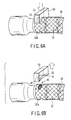
FIG. 6A is a perspective view showing a pushing-heating step, and a pushing-cooling step according to the first embodiment of the present invention; -
FIG. 6B is a perspective view showing a pulling-out step according to the first embodiment of the present invention; -
FIG. 7 is a perspective view showing a bending tube and a braid tube according to a second embodiment of the present invention; -
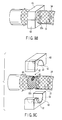
FIG. 8A is a perspective view showing a preparing step according to the second embodiment of the present invention; -
FIG. 8B is a perspective view showing a limiting-heating and heating-fusing step, and a limiting-cooling and cooling-joining step according to the second embodiment of the present invention; -
FIG. 8C is a perspective view showing a separating step according to the second embodiment of the present invention; -
FIG. 8D is a perspective view showing a cutting step according to the second embodiment of the present invention; -
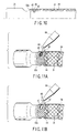
FIG. 9A is a perspective view showing a preparing step according to a third embodiment of the present invention; -
FIG. 9B is a perspective view showing a pushing-heating, and limiting-heating and heating-fusing step, and a pushing-cooling, and a limiting-cooling and cooling-joining step according to the third embodiment of the present invention; -
FIG. 9C is a perspective view showing a pulling-out and separating step according to the third embodiment of the present invention; -
FIG. 10 is a longitudinal sectional view showing a bending tube and a braid tube according to a forth embodiment of the present invention; -
FIG. 11A is a perspective view showing a early half of a filling step according to the forth embodiment of the present invention; -
FIG. 11B is a perspective view showing an after half of the filling step according to the forth embodiment of the present invention; -
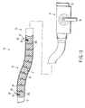
FIG. 12 is a schematic view showing an overtube for an endoscope according to fifth embodiment of the present invention; -
FIG. 13 is a perspective view showing a bending tube according to the fifth embodiment of the present invention; -
FIG. 14 is a perspective view showing the bending tube and a braid tube according to the fifth embodiment of the present invention; and -
FIG. 15 is a longitudinal sectional view showing the bending tube and the braid tube according to the fifth embodiment of the present invention. - Each embodiment of the present invention will hereinafter be described with reference to the drawings.
-
FIGS. 1 to 6B show first embodiment of the present invention. - Referring to
FIG. 1 , a schematic configuration of an endoscope as a medical insertion apparatus will be described. - The endoscope includes an elongate
endoscope insertion portion 22 configured to be inserted into the interior of the body. In theendoscope insertion portion 22, a distal endrigid portion 24, anendoscope bending portion 26 to be actuated to be bent, a long flexible endoscope insertion tube portion 28 is provided from the distal end side to the proximal end side. Theendoscope bending portion 26 includes a bendingtube 31 forming a framework of theendoscope bending portion 26. The bendingtube 31 is formed of substantially circularlycylindrical bending parts 32 coaxially connected to each other and rotatable with respect to each other. The outer peripheral portion of the bendingtube 31 is covered with abraid tube 34. Thebraid tube 34 is formed of strands as liner members made of a thermoplastic resin and braided into a circularly cylindrical shape. Both end portions of thebraid tube 34 are fixed to thebending parts tube 31 and form thefixed end portions 44, respectively. The outer peripheral portion of thebraid tube 34 is covered with an outer tube made of resin. Anendoscope operation portion 36 is connected to the proximal end portion of theendoscope insertion portion 22 and configured to be held and operated. A bendingoperation knob 38 is provided in theendoscope operation portion 36 and configured to operate theendoscope bending portion 26 to be bent. - Referring to
FIGS. 1 to 4 , a fixing mechanism fixing thebending parts braid tube 34 to each other will be described. - The bending
parts tube 31 includes circularly cylindrical body portion, respectively. A throughgroove 40 as a push-in receiving portion peripherally extends in the body portion of the bendingpart grooves 40 are located symmetrically with respect to the central axis of the bendingpart braid tube 34 includes a circularly tubular body portion. A protrudingportion 42 as a push-in portion is formed of a part of the body portion of thebraid tube 34 in each of thefixed end portions 44 at both ends of thebraid tube 34, and radially inwardly protrudes and peripherally extends. In the present embodiment, the two protrudingportions 42 is located symmetrically with the central axis of thebraid tube 34. Then, each of the protrudingportions 42 of thebraid tube 34 is pushed in each of the throughgrooves 40 of thebending parts fixed end portions 44 at both ends of thebraid tube 34 is fixed to each of thebending parts tube 31. - Referring to
FIG. 5 , a manufacturing apparatus for the endoscope bending portion will be described. - The manufacturing apparatus includes a pushing-in
instrument 50. Aplacement portion 51 is formed in the pushing-ininstrument 50 and has a shape of a circular arc whose inner diameter is large than the outer diameter of the bendingpart portion 52 protrudes from the central portion of theplacement portion 51, and has a shape corresponding with the shape of the protrudingportion 42 of thebraid tube 34 and slightly smaller than that. The pushing-ininstrument 50 is configured to be located such that the formingportion 52 faces the throughgroove 40 of the bendingpart part - A heater is built in the protruding forming
portion 52 of the pushing-ininstrument 50 and is connected to a power supply portion of anapparatus body 56 through anelectric cable 53. The protruding formingportion 52 of the pushing-ininstrument 50 is configured to be instantaneously heated up to a softening temperature at which the thermoplastic resin of thebraid tube 34 is softened, by supplying electric power to the heater from the power supply portion through theelectric cable 53. The pushing-ininstrument 50 is hollow, and the inner space of the pushing-ininstrument 50 is fluidly communicated with the blowingtube 54. The blowingtube 54 extends from the pushing-ininstrument 50 and is connected to a blowing portion of theapparatus body 56. The protruding formingportion 52 of the pushing-ininstrument 50 is configured instantaneously cooled using an air cooling by blowing air into the inside of the pushing-ininstrument 50 from the blowing portion through the blowingtube 54. - Referring to
FIGS. 6A and 6B , a manufacturing method for the endoscope bending portion will be described. - As a thermoplastic resin for forming the
braid tube 34 adapted for the manufacturing method according the present embodiment, polyamide and nylon, vinylon, polyester, polyethylene, and polypropylene, for example, is used, and polyethylene terephthalate out of polyester, and high density polyethylene out of polyethylene is preferably used. - Prepared is a bending
tube 31 formed of substantially circularlycylindrical bending parts 32 coaxially connected to each other and rotatable with respect to each other and abraid tube 34 formed of strands made of a thermoplastic resin and braided into circularly tubular shape. A protrudingportion 42 is not yet formed in thebraid tube 34 at this preparing stage. - The bending
tube 31 is covered with thebraid tube 34. Both ends of thebraid tube 34 are positioned in both ends of the bendingtube 31, respectively. - As is shown by an arrow in
FIG. 6A , the pushing-ininstrument 50 is radially inwardly moved so that theplacement portion 51 of the pushing-ininstrument 50 is placed on thebraid tube 34, and the protruding formingportion 52 radially inwardly presses a part of thebraid tube 34 so as to be push into a throughgroove 40 of the bendingpart 32a together with the protruding formingportion 52. The part of thebraid tube 34 pushed in the through groove40 is referred to as a protruding portion preparing portion. After that, the protruding formingportion 52 of the pushing-ininstrument 50 is instantaneously heated up to the softening temperature so that the protruding portion preparing portion of thebraid tube 34 is instantaneously heated up to the softening temperature to soften. It is noted that the protruding formingportion 52 may be previously heated up to the softening temperature before the pushing-in step and may be heated simultaneously with the pushing-in step. - Next, the protruding forming
portion 52 of the pushing-ininstrument 50 is instantaneously cooled so that the protruding portion preparing portion pushed in the throughgroove 40 and heated to soften is instantaneously cooled to set. - As is shown by an arrow in
FIG. 6B , the pushing-ininstrument 50 is radially outwardly moved so that the protruding formingportion 52 of the pushing-ininstrument 50 is pulled out from the through groove40 of the bendingpart 32a and the protrudingportion 42 of thebraid tube 34. Here, since the protruding formingportion 52 of the pushing-ininstrument 50 is instantaneously heated and cooled so that the protruding portion preparing portion is instantaneously heated and cooled, thebraid tube 34 is prevented from adhering to the protruding formingportion 52 and the outer surface thereof is finished to be smooth. - In this way, each of the protruding
portions 42 pushed in each of the throughgrooves 40 of each of the distal end and the proximalend bending part end portion 44 of thebraid tube 34, and each of thefixed end portions 44 is fixed to each of thebending parts - The outer peripheral portion of the
braid tube 34 is covered with an outer tube made of resin. - In the manufacturing method for the endoscope bending portion according to the present embodiment, the
braid tube 34 is fixed to the bendingpart braid tube 34 to be pushed into the throughgroove 40 of the bendingpart braid tube 34 to the bendingpart -
FIGS. 7 to 8D show a second embodiment of the present invention. - Referring to
FIG. 7 , as is similar to the first embodiment, each of protrudingportions 42 of each of fixedend portions 44 at both ends of abraid tube 34 is pushed into each of throughgrooves 40 of each of bendingparts tube 31 so that each of thefixed end portions 44 is fixed to each of thebending parts fixed end portion 44 as a limited portion and a joined portion, the outer diameter of thebraid tube 34 is limited so as to be substantially equal to the outer diameter of the bendingpart - Referring to
FIGS. 8A to 8D , a manufacturing apparatus for the endoscope bending portion will be described. - The manufacturing apparatus includes a pair of limiting-joining
instruments 58 as well as a pushing-ininstrument 50 similar to that of the first embodiment. A limiting-joiningsurface 59 is formed in the limiting-joininginstrument 58 and has a shape of a semicircle whose inner diameter is equal to the outer diameter of the bendingpart instruments 58 are configured to be located symmetrically with each other with respect to the central axis of the bendingpart surfaces 59 are parallel with the central axis of the distal end or the proximalend bending part surfaces 59 face the outer peripheral surface of the bendingpart instruments 58 are radially movable. When the limiting-joininginstruments 58 are in contact with each other, the limiting-joiningsurfaces 59 form a circularly peripheral surface whose inner diameter is equal to the outer diameter of the bendingpart instrument 50 are also used for the limiting-joininginstrument 58, and the limiting-joiningsurface 59 of the limiting-joininginstrument 58 is configured to be instantaneously heated up to a fusing temperature at which a thermoplastic resin is heated to fuse and is configured to be instantaneously cooled. Furthermore, the manufacturing apparatus includes amechanical cutter 60 configured to cut thebraid tube 34. - Referring to
FIGS. 8A to 8D , a manufacturing method for the endoscope bending portion will be described. - As is similar to the first embodiment, a preparing step, a braid tube covering step, a pushing-heating step, a pushing-cooling step, a pulling-out step are carried out. However, in the braid tube covering step, both ends of a
braid tube 34 is located so as to axially outwardly protrude beyond both ends of a bendingtube 31, respectively. - Referring to
FIGS. 8A to 8B , regarding each of regions of thebraid tube 34 covering each of a distal end and a proximalend bending part instruments 58 is radially inwardly moved to hold thebraid tube 34 and the bendingpart braid tube 34 is circumferentially pressed onto the peripheral surface of the bendingpart braid tube 34 is limited so as to be substantially equal to the outer diameter of the bendingpart braid tube 34 where the outer diameter is limited is referred to as the fixed end portion preparing portion. Next, the limiting-joiningsurfaces 59 are instantaneously heated up to the fusing temperature so that the fixed end portion preparing portion is instantaneously heated up to the fusing temperature. The fixed end portion preparing portion is heated to soften and a large number of strands in the fixed end portion preparing portion is heated to fuse. It is noted that the limiting-joiningsurface 59 may be previously heated up to the fusing temperature before the press onto thebraid tube 34 and may be heated simultaneously with the press onto thebraid tube 34. - Referring to
FIG. 8B , the limiting-joiningsurfaces 59 of the limiting-joininginstruments 58 are instantaneously cooled so that the fixed end portion preparing portion is instantaneously cooled to set and the large number of strands of the fixed end portion preparing portion is joined to each other. - Referring to
FIGS. 8B to 8C , the limiting-joininginstruments 58 are radially outwardly moved so that the limiting-joiningsurfaces 59 are separated from the fixed end portion preparing portion. Here, since the limiting-joiningsurface 59 of the limiting-joininginstrument 58 is instantaneously heated and cooled so that the fixed end portion preparing portion is instantaneously heated and cooled, thebraid tube 34 is prevented from adhering to the limiting-joiningsurface 59 and the outer surface thereof is finished to be smooth. It is noted that unnecessary parts is left radially outwardly extended from the fixed end portion preparing portion in thebraid tube 34. - The
braid tube 34 is peripherally cut in the axial end portion of the fixed end portion preparing portion. Since the larger number of strands is joined to each other in the fixed end portion preparing portion, the strands are not loosened in the cut portion even if the cutting is carried out using the normalmechanical cutter 60. - In this way, the
fixed end portion 44 is formed whose outer diameter is limited so as to be substantially equal to the outer diameter of the bendingpart - In the manufacturing method for the endoscope bending portion according to the present embodiment, it is facilitated to form the
fixed end portion 44 whose outer diameter is limited so as to be substantially equal to the outer diameter of the bendingpart -
FIGS. 9A to 9C show a third embodiment of the present invention. - An
endoscope bending portion 26 according to the present embodiment has the similar configuration as that of theendoscope bending portion 26 according to the second embodiment shown inFIG. 7 . - Referring to
FIG. 9A to 9C , a manufacturing apparatus for an endoscope bending portion will be described. - The manufacturing apparatus includes a pushing-limiting-joining
instrument 62. In the pushing-limiting-joininginstrument 62, the pushing-in instrument 50 (referring toFIG. 5 ) and the limiting-joining instrument 58 (referring toFIG. 8A ) are integrated with each other. That is, in the pushing-limiting-joininginstrument 62, the protruding formingportion 52 according to the first embodiment (referring toFIG. 5 ) protrudes from the limiting-joiningsurface 59 of the limiting-joininginstrument 58 according to the second embodiment(referring toFIG. 8A ). - Referring to
FIGS. 9A to 9C , a manufacturing method for an endoscope bending portion will be described. - As is similar to the second embodiment, a bending tube and a braid tube is prepared.
- Pushing-Heating, and Limiting-Heating and Heating-Fusing Step
- Referring to
FIGS. 9A to 9B , the pushing-limiting-joininginstruments 62 are radially inwardly moved, so that the protruding formingportion 52 of the pushing-limiting-joininginstrument 62 pushes a part of thebraid tube 34 into a throughgroove 40 and the limiting-joiningsurfaces 59 limit the outer diameter of thebraid tube 34 so as to be substantially equal to the outer diameter of the bendingpart portion 52 of the pushing-limiting-joininginstrument 62 is instantaneously heated up to the softening temperature and the limiting-joiningsurfaces 59 is instantaneously heated up to the fusing temperature so that a protruding portion preparing portion and a fixed end portion preparing portion of thebraid tube 34 is heated to soften and a number of strands in the fixed end portion preparing portion is heated to fuse. - Pushing-Cooling, and Limiting-Cooling and Cooling-Joining Step
- Referring to
FIG. 9B , the protruding formingportion 52 and the limiting-joiningsurfaces 59 of the pushing-limiting-joininginstrument 62 are instantaneously cooled so that the protruding portion preparing portion and the fixed end portion preparing portion are cooled to set and the number of strands in the fixed end portion preparing portion is joined to each other. - Referring to
FIGS. 9B to 9C , the pushing-limiting-joininginstruments 62 are radially outwardly moved so that the protruding formingportions 52 of the pushing-limiting-joininginstruments 62 are pulled out from the throughgrooves 40 of the bendingpart portion 42 of thebraid tube 34, and the limiting-joiningsurfaces 59 are separated from the fixed end portion preparing portion. - As is similar to the second embodiment, a cutting step and a covering step is carried out.
- In the manufacturing method for the endoscope bending portion according to the present embodiment, the pushing-heating step and the limiting-heating and heating-fusing step are carried out simultaneously with each other, the pushing-cooling step and the limiting-cooling and cooling-joining step are carried out simultaneously with each other, and the pulling-out step and the separating step are carried out simultaneously with each other, thereby simplifying a manufacturing process and reducing manufacturing time.
-
FIGS. 10 to 11B show a forth embodiment of the present invention. - Referring to
FIG. 10 , anendoscope bending portion 26 according to the present embodiment has the similar configuration to that of theendoscope bending portion 26 according to the second embodiment. In addition, ashape keeping portion 48 is formed within a substantially whole protrudingportion 42 having a concave shape, of thebraid tube 34 and keeps the shape of the protrudingportion 42. Theshape keeping portion 48 is formed of a thermoplastic adhesive 66 as a filler. - Referring to
FIGS. 11A to 11B , a manufacturing apparatus for an endoscope bending portion will be described. - The manufacturing apparatus has the similar configuration to that of the manufacturing apparatus according to the second embodiment. In addition, the manufacturing apparatus includes a filling mechanism. The filling mechanism is configured to discharge the thermoplastic adhesive 66 from a filling
nozzle 64. - Referring to
FIGS. 11A to 11B , a manufacturing method for the endoscope bending portion will be described. - As is similar to the second embodiment, a preparing step to a pulling-out step, a limiting-heating and heating-fusing step, a limiting-cooling and cooling-joining step, the separating step, and the cutting step is carried out.
- A
thermoplastic adhesive 66 heated to fuse is discharged from thefill nozzle 64 and is filled into a protrudingportion 42 having a concave shape of abraid tube 34. Next, thethermoplastic adhesive 66 is cooled to set. In this way, ashape keeping portion 48 keeping the shape of the protrudingportion 42 is formed within the substantially whole protrudingportion 42 having the concave shape, of thebraid tube 34. - In the manufacturing method for the endoscope bending portion according to the present embodiment, the
shape keeping portion 48 is formed just by filling the thermoplastic adhesive 66 into the protrudingportion 42 having the concave shape and cooling the thermoplastic adhesive 66 to set. Therefore, it is facilitated to form theshape keeping portion 48. - Regarding each embodiment mentioned above, the endoscope bending portion according to each embodiment is appropriate to be manufactured using the manufacturing method according to each embodiment, respectively. The manufacturing apparatus according to each embodiment is also appropriate to carry out the manufacturing method according to each embodiment, respectively.
-
FIGS. 12 to 15 show a fifth embodiment of the present invention. - Referring to
FIG. 12 , a schematic configuration of an overtube for an endoscope as a medical insertion apparatus will be described. - The overtube improves an insertion performance of an endoscope into the interior of the body. In the overtube, a channel extends over the total length of the overtube, and an endoscope is configured to be inserted through the channel and movable forward and backward. In the distal end side portion of the overtube, an elongate
tube insertion portion 70 is formed and is configured to be inserted into the interior of the body. In thetube insertion portion 70, a distal end projection anddepression portion 71 forming an outlet of the channel of the overtube, thetube bending portion 72 configured to be actuated to be bent, a long flexible tubeinsertion tube portion 73 is provided form the distal end side to the proximal end side. Here, the distal end projection anddepression portion 71 has a circularly cylindrical shape, and a distal end ring shape surface of the distal end projection anddepression portion 71 is inclined with respect to the longitudinal axis of thetube insertion portion 70, and the endoscope is configured to project from and depress into a distal end inclined opening of the distal end projection anddepression portion 71. Thetube bending portion 72 has the similar configuration to that of the endoscope bending portion according to the first embodiment. That is, thetube bending portion 72 is formed of a bendingtube 31 including bendingparts 32, abraid tube 34 and an outer tube, and a distal end and a proximal end fixedend portion 44 of thebraid tube 34 are fixed to bendingparts tube 31. Atube operation portion 74 is connected to the proximal end portion of thetube insertion portion 70. A bendingoperation lever 76 for operating thetube bending portion 72 to be bent is provided in thetube operation portion 74. A proximal end insertion and pulling-outportion 75 is provided at the proximal end portion of thetube operation portion 74 and forms an inlet of the channel of the overtube. The endoscope is configured to be inserted into and pulled out from a proximal end opening of the proximal end insertion and pulling-outportion 75. - Referring to
FIGS. 13 to 15 , a fixing mechanism fixing the bendingpart braid tube 34 will be described. - The fixing mechanism in the
tube bending portion 72 is similar to the fixing mechanism of the endoscope bending portion according to the first embodiment. That is, in thetube bending portion 72, a protrudingportion 42 as a push-in portion, of thefixed end portion 44 of thebraid tube 34 is pushed in a throughgroove 40 as a push-in receiving portion, of the bendingpart braid tube 34 is fixed to the bendingpart - A manufacturing method and a manufacturing apparatus for a tube bending portion according to the present embodiment is similar to the manufacturing method and the manufacturing apparatus for the endoscope bending portion according to the first embodiment.
- The
tube bending portion 72, and the manufacturing method and a manufacturing apparatus thereof according to the present embodiment includes the similar effects to those of the endoscope bending portion, and the manufacturing method and the manufacturing apparatus thereof according to the first embodiment. - Moreover, a tube bending portion, and a manufacturing method and a manufacturing apparatus thereof similar to the endoscope bending portion, and the manufacturing method and the manufacturing apparatus according to any of the second to the forth embodiments may used.
Claims (29)
- A bending portion of a medical insertion apparatus characterized by comprising:a bending tube (31) including cylindrical bending parts (32a, 32b) coaxially connected to each other and rotatable with respect to each other; anda braid tube (34) covering an outer peripheral portion of the bending tube (31), and including liner members made of a thermoplastic resin and forming a netlike shape, andwherein the braid tube (34) includes a push-in portion (42) formed of a part of the braid tube (34) and protruding inwardly, andthe bending tube (31) includes a push-in receiving portion (40) provided with the bending part (32a, 32b) and in which the push-in portion (42) is pushed.
- The bending portion of the medical insertion apparatus according to claim 1, characterized in that the braid tube (34) includes a limited portion (44) whose outer diameter of the limited portion (44) is limited so as to be substantially equal to an outer diameter of the bending part (32a, 32b).
- The bending portion of the medical insertion apparatus according to claim 1, characterized in that the braid tube (34) includes a joined portion (44) provided on an end portion of the braid tube (34) and in which the liner members are joined to each other.
- The bending portion of the medical insertion apparatus according to claim 1, characterized in that the push-in portion (42) has a concave shape, and the braid tube (34) includes a shape keeping portion (48) provided within the push-in portion (42) and keeping the shape of the push-in portion (42).
- An endoscope characterized by comprising the bending portion of the medical insertion apparatus according to any one of claims 1 to 4.
- An overtube for an endoscope characterized by comprising the bending portion of the medical insertion apparatus according to any one of claims 1 to 4.
- A manufacturing method for a bending portion of a medical insertion apparatus, characterized by comprising;
preparing a bending tube (31) including cylindrical bending parts (32a, 32b) coaxially connected to each other and rotatable with respect to each other;
preparing a braid tube (34) including liner members made of a thermoplastic resin and forming a netlike shape;
covering the braid tube (34) on an outer peripheral portion of the bending tube (31);
pushing-heating of protruding inwardly a part of the braid tube (34) to be pushed into a push-in receiving portion(40) of the bending part (32a, 32b) and heating the part to soften; and
pushing-cooling of cooling the part to set. - A manufacturing method for the bending portion of the medical insertion apparatus according to claim 7, characterized by further comprising:limiting-heating of limiting an outer diameter of the braid tube (34) so as to be substantially equal to an outer diameter of the bending part (32a, 32b) in a region of the braid tube (34) and heating the region to soften; andlimitin-cooling of cooling the region to set.
- The manufacturing method for the bending portion of the medical insertion apparatus according to claim 7, characterized by further comprising:heating-fusing of heating the liner members to fuse in a region of the braid tube (34);cooling-joining of cooling the liner members fused by heating to set and to be joined to each other;cutting the braid tube (34) in the region.
- The manufacturing method for the bending portion of the medical insertion apparatus according to claim 7, characterized by further comprising:limiting-heating and heating-fusing of limiting an outer diameter of the braid tube (34) so as to be substantially equal to an outer diameter of the bending part (32a, 32b) in a region of the braid tube (34) and heating the region to soften, and heating the liner members to fuse;limiting-cooling and cooling-joining of cooling the region to set, and cooling the liner members fused by heating to set and to be joined to each other; andcutting the braid tube (34) in the region.
- The manufacturing method for the bending portion of the medical insertion apparatus according to claim 10, characterized in that the pushing-heating, and the limiting-heating and heating-fusing are carried out simultaneously with each other, and
the pushing-cooling, and the limit-cooling and cooling-joining are carried out simultaneously with each other. - The manufacturing method for the bending portion of the medical insertion apparatus according to claim 7, characterized by further comprising
filling-setting of filling a filler (66) into a part having a concave shape of the braid tube (34) from outside to set. - The manufacturing method for the bending portion of the medical insertion apparatus according to claim 12, characterized in that
the filler (66) is a thermoplastic adhesive(66). - A manufacturing method for an endoscope, characterized by comprising the manufacturing method for the bending portion of the medical insertion apparatus according to any one of claims 7 to 13.
- A manufacturing method for an overtube for an endoscope, characterized by comprising the manufacturing method for the bending portion of the medical insertion apparatus according to any one of claims 7 to 13.
- A manufacturing apparatus for a bending portion of a medical insertion apparatus,
wherein the bending portion includes: a bending tube (31) including cylindrical bending parts (32a, 32b) coaxially connected to each other and rotatable with respect to each other; and a braid tube (34) covering an outer peripheral portion of the bending tube (31), and including liner members made of a thermoplastic resin and forming a netlike shape, the manufacturing apparatus characterized by comprising:a pushing-in instrument (50) configured to protrude inwardly a part of the braid tube (34) to be pushed into a push-in receiving portion (40) of the bending part (32a, 32b); anda pushing-in instrument heating mechanism (53, 56) configured to heat the pushing-in instrument (50). - The manufacturing apparatus for the bending portion of the medical insertion apparatus according to claim 16, characterized by further comprising
a pushing-in instrument cooling mechanism (54, 56) configured to cool the pushing-in instrument (50). - The manufacturing apparatus for the bending portion of the medical insertion apparatus according to claim 16, characterized by further comprising:a limiting instrument (58) configured to limit an outer diameter of the braid tube (34) so as to be substantially equal to an outer diameter of the bending part (32a, 32b) in a region of the braid tube (34); anda limiting instrument heating mechanism (53, 56) configured to heat the limiting instrument (58).
- The manufacturing apparatus for the bending portion of the medical insertion apparatus according to claim 18, characterized by further comprising
a limiting instrument cooling mechanism (54, 56) configured to cool the limiting instrument (58). - The manufacturing apparatus for the bending portion of the medical insertion apparatus according to claim 16, characterized by further comprising:a joining instrument (58) configured to join the liner members in a region of the braid tube (34);a joining instrument heating mechanism (53, 56) configured to heat the joining instrument (58); anda cutting mechanism (60) configured to cut the braid tube (34) in the region.
- The manufacturing apparatus for the bending portion of the medical insertion apparatus according to claim 20, characterize by further comprising
a joining instrument cooling mechanism (54, 56) configured to cool the joining instrument (58). - The manufacturing apparatus for the bending portion of the medical insertion apparatus according to claim 16, characterized by further comprising:a limiting-joining instrument (58) configured to limit an outer diameter of the braid tube (34) so as to be substantially equal to an outer diameter of the bending part (32a, 32b) in a region of the braid tube (34) and join the liner members in the region;a limiting-joining instrument heating mechanism (53, 56) configured to heat the limiting-joining instrument (58); anda cutting mechanism (60) configured to cut the braid tube (34).
- The manufacturing apparatus for the bending portion of the medical insertion apparatus according to claim 22, characterized by further comprising
a limiting-joining instrument cooling mechanism (54, 56) configured to cool the limiting-joining instrument (58). - The manufacturing apparatus for the bending portion of the medical insertion apparatus according to claim 22, characterized by further comprising:a pushing-in and limiting-joining instrument (62) including the pushing-in instrument (50) and the limiting-joining instrument (58); anda pushing-in and limiting-joining instrument heating mechanism (53, 56) including a pushing-in instrument heating mechanism (53, 56) and a limiting-joining instrument heating mechanism (53, 56).
- The manufacturing apparatus for the bending portion of the medical insertion apparatus according to claim 24, characterized by further comprising
a pushing-in and limiting-joining instrument cooling mechanism (54, 56) including a pushing-in instrument cooling mechanism (54, 56) configured to cool the pushing-in instrument (50) and a limiting-joining instrument cooling mechanism (54, 56) configured to cool the limiting-joining instrument (58). - The manufacturing apparatus for the bending portion of the medical insertion apparatus according to claim 16, characterized by further comprising
a filling mechanism (64) configured to fill a filler (66). - The manufacturing apparatus for the bending portion of the medical insertion apparatus according to claim 26, characterized in that
the filling mechanism (64) includes a thermoplastic adhesive filling mechanism (64) configured to fill a thermoplastic adhesive (66). - A manufacturing apparatus for an endoscope, characterized by comprising the manufacturing apparatus for the bending portion of the medical insertion apparatus according to any one of claims 16 to 27.
- A manufacturing apparatus for an overtube for an endoscope, characterized by comprising the manufacturing apparatus for the bending portion of the medical insertion apparatus according to any one of claims 16 to 27.
Applications Claiming Priority (2)
| Application Number | Priority Date | Filing Date | Title |
|---|---|---|---|
| JP2008097431A JP2009247498A (en) | 2008-04-03 | 2008-04-03 | Bending portion of medical insertion apparatus, and manufacturing method and manufacturing apparatus thereof |
| US4320008P | 2008-04-08 | 2008-04-08 |
Publications (2)
| Publication Number | Publication Date |
|---|---|
| EP2111784A2 true EP2111784A2 (en) | 2009-10-28 |
| EP2111784A3 EP2111784A3 (en) | 2009-11-25 |
Family
ID=40846935
Family Applications (1)
| Application Number | Title | Priority Date | Filing Date |
|---|---|---|---|
| EP09156320A Withdrawn EP2111784A3 (en) | 2008-04-03 | 2009-03-26 | Bending portion of medical insertion apparatus, and manufacturing method and manufacturing apparatus thereof |
Country Status (3)
| Country | Link |
|---|---|
| US (1) | US20090253963A1 (en) |
| EP (1) | EP2111784A3 (en) |
| JP (1) | JP2009247498A (en) |
Families Citing this family (6)
| Publication number | Priority date | Publication date | Assignee | Title |
|---|---|---|---|---|
| US9486605B2 (en) * | 2011-07-15 | 2016-11-08 | Cook Medical Technologies Llc | Introducer sheath with braided filament securement mechanism |
| JP2020010761A (en) * | 2018-07-13 | 2020-01-23 | オリンパス株式会社 | Net-like tube, and manufacturing method of net-like tube |
| JP7233907B2 (en) * | 2018-12-13 | 2023-03-07 | オリンパス株式会社 | Method for manufacturing tube body |
| DE102020111455A1 (en) * | 2020-04-27 | 2021-10-28 | Schölly Fiberoptic GmbH | Flexible endoscope based on an investment material |
| DE102020111458A1 (en) * | 2020-04-27 | 2021-10-28 | Schölly Fiberoptic GmbH | Flexible endoscope with a skeletal structure |
| CN112339280B (en) * | 2020-10-23 | 2022-09-02 | 河北华盾管道制造有限公司 | High density polyethylene pipe fitting tubular product splicing apparatus |
Citations (1)
| Publication number | Priority date | Publication date | Assignee | Title |
|---|---|---|---|---|
| JPH11206701A (en) | 1998-01-21 | 1999-08-03 | Olympus Optical Co Ltd | Endoscope |
Family Cites Families (12)
| Publication number | Priority date | Publication date | Assignee | Title |
|---|---|---|---|---|
| US3162214A (en) * | 1963-01-16 | 1964-12-22 | American Optical Corp | Flexible tubular structures |
| JPS506192A (en) * | 1973-05-18 | 1975-01-22 | ||
| US4944287A (en) * | 1988-03-29 | 1990-07-31 | Asahi Kogaku Kogyo K.K. | Flexible tube of endoscope |
| US4869238A (en) * | 1988-04-22 | 1989-09-26 | Opielab, Inc. | Endoscope for use with a disposable sheath |
| US4947827A (en) * | 1988-12-30 | 1990-08-14 | Opielab, Inc. | Flexible endoscope |
| JP2524408B2 (en) * | 1989-08-01 | 1996-08-14 | オリンパス光学工業株式会社 | Endoscope |
| JP3181331B2 (en) * | 1991-10-04 | 2001-07-03 | 株式会社町田製作所 | Endoscope |
| JP3149219B2 (en) * | 1991-10-15 | 2001-03-26 | 旭光学工業株式会社 | Covering structure of curved part of endoscope |
| US5465710A (en) * | 1993-05-12 | 1995-11-14 | Machida Endoscope Co., Ltd. | Endoscope |
| US6520214B1 (en) * | 1999-04-13 | 2003-02-18 | Pentax Corporation | Flexible tube for endoscope |
| JP4047069B2 (en) * | 2002-05-21 | 2008-02-13 | ペンタックス株式会社 | Endoscope flexible tube and endoscope |
| JP2006334287A (en) * | 2005-06-06 | 2006-12-14 | Olympus Medical Systems Corp | Flexible tube of endoscope |
-
2008
- 2008-04-03 JP JP2008097431A patent/JP2009247498A/en active Pending
-
2009
- 2009-03-26 EP EP09156320A patent/EP2111784A3/en not_active Withdrawn
- 2009-04-02 US US12/416,978 patent/US20090253963A1/en not_active Abandoned
Patent Citations (1)
| Publication number | Priority date | Publication date | Assignee | Title |
|---|---|---|---|---|
| JPH11206701A (en) | 1998-01-21 | 1999-08-03 | Olympus Optical Co Ltd | Endoscope |
Also Published As
| Publication number | Publication date |
|---|---|
| JP2009247498A (en) | 2009-10-29 |
| US20090253963A1 (en) | 2009-10-08 |
| EP2111784A3 (en) | 2009-11-25 |
Similar Documents
| Publication | Publication Date | Title |
|---|---|---|
| EP2111784A2 (en) | Bending portion of medical insertion apparatus, and manufacturing method and manufacturing apparatus thereof | |
| JP6666699B2 (en) | Connection method | |
| US8037590B2 (en) | Method of constructing an articulation joint for steerable medical device | |
| US7588580B2 (en) | Mucosa excision device using endoscope | |
| JP5703344B2 (en) | Removable tip for laparoscopic device | |
| EP2074927B1 (en) | Endoscope | |
| JP2007082815A (en) | Curved part of endoscope and endoscope | |
| US20170000318A1 (en) | Stent delivery system | |
| EP1872730B1 (en) | Endoscopic treatment instrument | |
| JP2009247624A (en) | Endoscope, connection method of flexible section and bending section in endoscope, production method of endoscope provided with this connection method, endoscope overtube, connection method of flexible section and bending section in endoscope overtube, and production method of endoscope overtube provided with this connection method | |
| CN112402008A (en) | Radio frequency ablation catheter and system thereof | |
| EP1920740B1 (en) | Stent supply instrument | |
| JP2002125916A (en) | Endoscope | |
| JP2006068406A (en) | High frequency snare for endoscope and manufacturing method of the same | |
| US8696657B2 (en) | Treatment tool | |
| US20220226007A1 (en) | Basket-type treatment tool for endoscope | |
| US20170304591A1 (en) | Catheter | |
| JP2007151913A (en) | Forceps apparatus and exterior tube applying method to contact coil thereof | |
| JP3969856B2 (en) | Endoscope | |
| JP6735202B2 (en) | Endoscopic treatment instrument and method for manufacturing endoscopic treatment instrument | |
| JP4615935B2 (en) | Endoscope flexible tube and manufacturing method thereof | |
| JP4192180B2 (en) | Catheter manufacturing method | |
| JP2007143848A (en) | Bending part of endoscope, endoscope, and method for manufacturing bending part | |
| WO2024090368A1 (en) | Medical shaft and method for producing medical shaft | |
| WO2018062415A1 (en) | Endoscopic treatment tool and production method for endoscopic treatment tool |
Legal Events
| Date | Code | Title | Description |
|---|---|---|---|
| PUAI | Public reference made under article 153(3) epc to a published international application that has entered the european phase |
Free format text: ORIGINAL CODE: 0009012 |
|
| PUAL | Search report despatched |
Free format text: ORIGINAL CODE: 0009013 |
|
| AK | Designated contracting states |
Kind code of ref document: A2 Designated state(s): AT BE BG CH CY CZ DE DK EE ES FI FR GB GR HR HU IE IS IT LI LT LU LV MC MK MT NL NO PL PT RO SE SI SK TR |
|
| AX | Request for extension of the european patent |
Extension state: AL BA RS |
|
| AK | Designated contracting states |
Kind code of ref document: A3 Designated state(s): AT BE BG CH CY CZ DE DK EE ES FI FR GB GR HR HU IE IS IT LI LT LU LV MC MK MT NL NO PL PT RO SE SI SK TR |
|
| AX | Request for extension of the european patent |
Extension state: AL BA RS |
|
| 17P | Request for examination filed |
Effective date: 20100308 |
|
| AKX | Designation fees paid |
Designated state(s): DE FR GB IE |
|
| 17Q | First examination report despatched |
Effective date: 20110114 |
|
| STAA | Information on the status of an ep patent application or granted ep patent |
Free format text: STATUS: THE APPLICATION IS DEEMED TO BE WITHDRAWN |
|
| 18D | Application deemed to be withdrawn |
Effective date: 20131001 |