EP2111504B1 - Control apparatus for internal combustion engine and method for controlling the same - Google Patents
Control apparatus for internal combustion engine and method for controlling the same Download PDFInfo
- Publication number
- EP2111504B1 EP2111504B1 EP08709770A EP08709770A EP2111504B1 EP 2111504 B1 EP2111504 B1 EP 2111504B1 EP 08709770 A EP08709770 A EP 08709770A EP 08709770 A EP08709770 A EP 08709770A EP 2111504 B1 EP2111504 B1 EP 2111504B1
- Authority
- EP
- European Patent Office
- Prior art keywords
- exhaust gas
- intercooler
- condensed water
- water obtained
- passage
- Prior art date
- Legal status (The legal status is an assumption and is not a legal conclusion. Google has not performed a legal analysis and makes no representation as to the accuracy of the status listed.)
- Expired - Fee Related
Links
Images


Classifications
-
- F—MECHANICAL ENGINEERING; LIGHTING; HEATING; WEAPONS; BLASTING
- F02—COMBUSTION ENGINES; HOT-GAS OR COMBUSTION-PRODUCT ENGINE PLANTS
- F02B—INTERNAL-COMBUSTION PISTON ENGINES; COMBUSTION ENGINES IN GENERAL
- F02B29/00—Engines characterised by provision for charging or scavenging not provided for in groups F02B25/00, F02B27/00 or F02B33/00 - F02B39/00; Details thereof
- F02B29/04—Cooling of air intake supply
- F02B29/0406—Layout of the intake air cooling or coolant circuit
- F02B29/0418—Layout of the intake air cooling or coolant circuit the intake air cooler having a bypass or multiple flow paths within the heat exchanger to vary the effective heat transfer surface
-
- F—MECHANICAL ENGINEERING; LIGHTING; HEATING; WEAPONS; BLASTING
- F02—COMBUSTION ENGINES; HOT-GAS OR COMBUSTION-PRODUCT ENGINE PLANTS
- F02D—CONTROLLING COMBUSTION ENGINES
- F02D41/00—Electrical control of supply of combustible mixture or its constituents
- F02D41/0025—Controlling engines characterised by use of non-liquid fuels, pluralities of fuels, or non-fuel substances added to the combustible mixtures
- F02D41/0047—Controlling exhaust gas recirculation [EGR]
- F02D41/0065—Specific aspects of external EGR control
-
- F—MECHANICAL ENGINEERING; LIGHTING; HEATING; WEAPONS; BLASTING
- F02—COMBUSTION ENGINES; HOT-GAS OR COMBUSTION-PRODUCT ENGINE PLANTS
- F02M—SUPPLYING COMBUSTION ENGINES IN GENERAL WITH COMBUSTIBLE MIXTURES OR CONSTITUENTS THEREOF
- F02M26/00—Engine-pertinent apparatus for adding exhaust gases to combustion-air, main fuel or fuel-air mixture, e.g. by exhaust gas recirculation [EGR] systems
- F02M26/02—EGR systems specially adapted for supercharged engines
- F02M26/04—EGR systems specially adapted for supercharged engines with a single turbocharger
- F02M26/06—Low pressure loops, i.e. wherein recirculated exhaust gas is taken out from the exhaust downstream of the turbocharger turbine and reintroduced into the intake system upstream of the compressor
-
- F—MECHANICAL ENGINEERING; LIGHTING; HEATING; WEAPONS; BLASTING
- F02—COMBUSTION ENGINES; HOT-GAS OR COMBUSTION-PRODUCT ENGINE PLANTS
- F02M—SUPPLYING COMBUSTION ENGINES IN GENERAL WITH COMBUSTIBLE MIXTURES OR CONSTITUENTS THEREOF
- F02M26/00—Engine-pertinent apparatus for adding exhaust gases to combustion-air, main fuel or fuel-air mixture, e.g. by exhaust gas recirculation [EGR] systems
- F02M26/13—Arrangement or layout of EGR passages, e.g. in relation to specific engine parts or for incorporation of accessories
- F02M26/14—Arrangement or layout of EGR passages, e.g. in relation to specific engine parts or for incorporation of accessories in relation to the exhaust system
- F02M26/15—Arrangement or layout of EGR passages, e.g. in relation to specific engine parts or for incorporation of accessories in relation to the exhaust system in relation to engine exhaust purifying apparatus
-
- F—MECHANICAL ENGINEERING; LIGHTING; HEATING; WEAPONS; BLASTING
- F02—COMBUSTION ENGINES; HOT-GAS OR COMBUSTION-PRODUCT ENGINE PLANTS
- F02M—SUPPLYING COMBUSTION ENGINES IN GENERAL WITH COMBUSTIBLE MIXTURES OR CONSTITUENTS THEREOF
- F02M26/00—Engine-pertinent apparatus for adding exhaust gases to combustion-air, main fuel or fuel-air mixture, e.g. by exhaust gas recirculation [EGR] systems
- F02M26/45—Sensors specially adapted for EGR systems
- F02M26/46—Sensors specially adapted for EGR systems for determining the characteristics of gases, e.g. composition
-
- F—MECHANICAL ENGINEERING; LIGHTING; HEATING; WEAPONS; BLASTING
- F02—COMBUSTION ENGINES; HOT-GAS OR COMBUSTION-PRODUCT ENGINE PLANTS
- F02M—SUPPLYING COMBUSTION ENGINES IN GENERAL WITH COMBUSTIBLE MIXTURES OR CONSTITUENTS THEREOF
- F02M26/00—Engine-pertinent apparatus for adding exhaust gases to combustion-air, main fuel or fuel-air mixture, e.g. by exhaust gas recirculation [EGR] systems
- F02M26/50—Arrangements or methods for preventing or reducing deposits, corrosion or wear caused by impurities
-
- F—MECHANICAL ENGINEERING; LIGHTING; HEATING; WEAPONS; BLASTING
- F02—COMBUSTION ENGINES; HOT-GAS OR COMBUSTION-PRODUCT ENGINE PLANTS
- F02D—CONTROLLING COMBUSTION ENGINES
- F02D2200/00—Input parameters for engine control
- F02D2200/02—Input parameters for engine control the parameters being related to the engine
- F02D2200/04—Engine intake system parameters
- F02D2200/0418—Air humidity
-
- F—MECHANICAL ENGINEERING; LIGHTING; HEATING; WEAPONS; BLASTING
- F02—COMBUSTION ENGINES; HOT-GAS OR COMBUSTION-PRODUCT ENGINE PLANTS
- F02M—SUPPLYING COMBUSTION ENGINES IN GENERAL WITH COMBUSTIBLE MIXTURES OR CONSTITUENTS THEREOF
- F02M26/00—Engine-pertinent apparatus for adding exhaust gases to combustion-air, main fuel or fuel-air mixture, e.g. by exhaust gas recirculation [EGR] systems
- F02M26/02—EGR systems specially adapted for supercharged engines
- F02M26/04—EGR systems specially adapted for supercharged engines with a single turbocharger
- F02M26/05—High pressure loops, i.e. wherein recirculated exhaust gas is taken out from the exhaust system upstream of the turbine and reintroduced into the intake system downstream of the compressor
-
- F—MECHANICAL ENGINEERING; LIGHTING; HEATING; WEAPONS; BLASTING
- F02—COMBUSTION ENGINES; HOT-GAS OR COMBUSTION-PRODUCT ENGINE PLANTS
- F02M—SUPPLYING COMBUSTION ENGINES IN GENERAL WITH COMBUSTIBLE MIXTURES OR CONSTITUENTS THEREOF
- F02M26/00—Engine-pertinent apparatus for adding exhaust gases to combustion-air, main fuel or fuel-air mixture, e.g. by exhaust gas recirculation [EGR] systems
- F02M26/13—Arrangement or layout of EGR passages, e.g. in relation to specific engine parts or for incorporation of accessories
- F02M26/22—Arrangement or layout of EGR passages, e.g. in relation to specific engine parts or for incorporation of accessories with coolers in the recirculation passage
- F02M26/23—Layout, e.g. schematics
-
- F—MECHANICAL ENGINEERING; LIGHTING; HEATING; WEAPONS; BLASTING
- F02—COMBUSTION ENGINES; HOT-GAS OR COMBUSTION-PRODUCT ENGINE PLANTS
- F02M—SUPPLYING COMBUSTION ENGINES IN GENERAL WITH COMBUSTIBLE MIXTURES OR CONSTITUENTS THEREOF
- F02M26/00—Engine-pertinent apparatus for adding exhaust gases to combustion-air, main fuel or fuel-air mixture, e.g. by exhaust gas recirculation [EGR] systems
- F02M26/13—Arrangement or layout of EGR passages, e.g. in relation to specific engine parts or for incorporation of accessories
- F02M26/38—Arrangement or layout of EGR passages, e.g. in relation to specific engine parts or for incorporation of accessories with two or more EGR valves disposed in parallel
-
- Y—GENERAL TAGGING OF NEW TECHNOLOGICAL DEVELOPMENTS; GENERAL TAGGING OF CROSS-SECTIONAL TECHNOLOGIES SPANNING OVER SEVERAL SECTIONS OF THE IPC; TECHNICAL SUBJECTS COVERED BY FORMER USPC CROSS-REFERENCE ART COLLECTIONS [XRACs] AND DIGESTS
- Y02—TECHNOLOGIES OR APPLICATIONS FOR MITIGATION OR ADAPTATION AGAINST CLIMATE CHANGE
- Y02T—CLIMATE CHANGE MITIGATION TECHNOLOGIES RELATED TO TRANSPORTATION
- Y02T10/00—Road transport of goods or passengers
- Y02T10/10—Internal combustion engine [ICE] based vehicles
- Y02T10/12—Improving ICE efficiencies
-
- Y—GENERAL TAGGING OF NEW TECHNOLOGICAL DEVELOPMENTS; GENERAL TAGGING OF CROSS-SECTIONAL TECHNOLOGIES SPANNING OVER SEVERAL SECTIONS OF THE IPC; TECHNICAL SUBJECTS COVERED BY FORMER USPC CROSS-REFERENCE ART COLLECTIONS [XRACs] AND DIGESTS
- Y02—TECHNOLOGIES OR APPLICATIONS FOR MITIGATION OR ADAPTATION AGAINST CLIMATE CHANGE
- Y02T—CLIMATE CHANGE MITIGATION TECHNOLOGIES RELATED TO TRANSPORTATION
- Y02T10/00—Road transport of goods or passengers
- Y02T10/10—Internal combustion engine [ICE] based vehicles
- Y02T10/40—Engine management systems
Definitions
- the invention relates to a control apparatus for an internal combustion engine, which includes an exhaust gas recirculation passage through which exhaust gas is recirculated back from an exhaust passage to an intake passage, and a method for controlling the same.
- an exhaust gas recirculation (EGR) system for an internal combustion engine, for example, a diesel engine.
- the exhaust gas recirculation system recirculates a portion of exhaust gas back from an exhaust passage to an intake passage to decrease the combustion temperature in the engine, thereby suppressing generation of NOx.
- an EGR system that recirculates exhaust gas back to an intake system from an exhaust passage at a portion downstream of a catalyst (hereinafter, referred to as a "low-pressure loop EGR system”) has been suggested.
- JP-A-2005-146919 describes a technology related to a low-pressure loop EGR system.
- the bypass passage passes close by the engine.
- JP-A-2005-146919 has a disadvantage that the intercooler may corrode if the condensed water, which is obtained from the exhaust gas and recirculated by the low-pressure EGR system, is supplied to the intercooler. Such corrosion may occur if strongly acidic condensed water is supplied to the intercooler.
- the invention provides a control apparatus for an internal combustion engine that executes a control for supplying an intake air to a bypass passage, through which an intake air flow bypasses an intercooler, based on the pH of the condensed water obtained from the exhaust gas, thereby ensuring reliability of the intercooler, and a method for controlling the control apparatus.
- a first aspect of the invention relates to a control apparatus for an internal combustion engine.
- the control apparatus includes: an exhaust gas recirculation unit that recirculates exhaust gas back from an exhaust passage, at a portion downstream of a turbine of a turbocharger and a catalyst, to an intake passage, at a portion upstream of a compressor of the turbocharger; an intercooler that is provided in the intake passage, at a position downstream of a position to which the exhaust gas is recirculated back by the exhaust gas recirculation unit; a bypass passage through which an intake air flow bypasses the intercooler; a pH determination unit that determines a pH of the condensed water obtained from the exhaust gas recirculated back by the exhaust gas recirculation unit by estimation or detection; a corrosion determination unit that determines whether the pH of the condensed water obtained from the exhaust gas is at a level at which the intercooler corrodes, based on the pH determined by the pH determination unit; and a bypass control unit that executes a control for
- the control apparatus is appropriately applied to, for example, a diesel engine provided with a turbocharger.
- the exhaust gas recirculation unit recirculates the exhaust gas back from the exhaust passage, at the portion downstream of the turbine of the turbocharger and the catalyst, to the intake passage, at the portion upstream of the compressor of the turbocharger.
- the intercooler is provided in the intake passage, at the position downstream of the position to which the exhaust gas is recirculated back by the exhaust gas recirculation system. The intercooler cools the gas that is supplied thereto.
- the intake air flow bypasses the intercooler through the bypass passage.
- the pH determination unit determines the pH of the condensed water obtained from the exhaust gas recirculated back by the exhaust gas recirculation unit by estimation or detection.
- the corrosion determination unit determines whether the pH of the condensed water obtained from the exhaust gas is at the level at which the intercooler corrodes.
- the bypass control unit executes the control for cutting off the flow of the intake air (fluid that contains not only the air take in from the outside of the vehicle but also the exhaust gas that is recirculated by exhaust gas recirculation unit and the condensed water obtained from the exhaust gas) toward the intercooler to direct the intake air flow only to the bypass passage, when the corrosion determination unit determines that the pH of the condensed water obtained from the exhaust gas is at the level at which the intercooler corrodes in the state where the exhaust gas is recirculated back by the exhaust gas recirculation unit.
- the corrosion determination unit determines that the pH of the condensed water obtained from the exhaust gas is at the level at which the intercooler corrodes in the state where the exhaust gas is recirculated back by the exhaust gas recirculation unit.
- the pH determination unit may estimate the pH of the condensed water obtained from the exhaust gas, based on at least one of the rotational speed of the internal combustion engine, the fuel injection amount, and the temperature of the catalyst. Thus, it is possible to accurately estimate the pH of the condensed water obtained from the exhaust gas.
- the pH determination unit may detect the pH of the condensed water obtained from the exhaust gas using a sensor that is provided to the intake passage, at a position upstream of the position at which the intercooler is provided and downstream of the position to which the exhaust gas is recirculated back by the exhaust gas recirculation unit.
- the bypass passage is defined by a member that is made of a material having a high corrosion resistance.
- a member that is made of a material having a high corrosion resistance it is possible to appropriately prevent occurrence of corrosion in the bypass passage, even when strongly acidic exhaust gas condensed water is supplied to the bypass passage.
- a second aspect of the invention relates to a method for controlling a control apparatus for an internal combustion engine.
- the control apparatus includes: an exhaust gas recirculation unit that recirculates exhaust gas back from an exhaust passage, at a portion downstream of a turbine of a turbocharger and a catalyst, to an intake passage, at a portion upstream of a compressor of the turbocharger; an intercooler that is provided in the intake passage, at a position downstream of a position to which the exhaust gas is recirculated back by the exhaust gas recirculation unit; and a bypass passage through which an intake air flow bypasses the intercooler.
- a pH of the condensed water obtained from the exhaust gas recirculated back by the exhaust gas recirculation unit is determined by estimation or detection, and whether the pH of the condensed water obtained from the exhaust gas is at a level at which the intercooler corrodes is determined based on the determined pH. Then, a control for cutting off an intake air flow toward the intercooler to direct the intake air flow only to the bypass passage is executed, when it is determined that the pH of the condensed water obtained from the exhaust gas is at the level at which the intercooler corrodes in a state where the exhaust gas is recirculated back by the exhaust gas recirculation unit.
- FIG 1 is a block diagram schematically showing the structure of a control apparatus 100 for an internal combustion engine according to the first embodiment of the invention.
- solid arrows indicate a flow of the intake air and a flow of the exhaust gas
- dashed arrows indicate control signals and detection signals.
- the control apparatus 100 in FIG 1 includes an internal combustion engine 10 that is an in-line four-cylinder diesel engine. Each cylinder of the internal combustion engine 10 is connected to an intake manifold 11 and an exhaust manifold 12.
- the internal combustion engine 10 has fuel injection valves 15 provided to the respective cylinders, and a common-rail 14 that supplies high-pressure fuel to the fuel injection valves 15.
- the high-pressure fuel is supplied to the common-rail 14 by a fuel pump (not shown).
- An engine speed sensor 42 detects the rotational speed of the internal combustion engine 10, and transmits a detection signal S42 indicating the engine speed to an ECU 7.
- a coolant temperature sensor 43 detects the temperature of a coolant (hereinafter, referred to as "coolant temperature”) that cools the internal combustion engine 10, etc., and transmits a detection signal S43 indicating the coolant temperature to the ECU 7.
- An intake passage 20 is connected to the intake manifold 11. Connected to the intake passage 20 are: an air cleaner 21 that purifies the air flowing into the internal combustion engine 10; an intake air temperature sensor 41 that detects the intake air temperature; a throttle valve 22a; a blow-by gas supply unit 19 that recirculates blow-by gas extracted from, for example, a crankcase back to an intake system; a compressor 23a of a turbocharger 23; an intercooler (IC) 24 that cools the intake air; and a throttle valve 22b.
- the intake passage 20 has a bypass passage 27 through which the intake air flow bypasses the intercooler 24. In this case, the bypass passage 27 is connected to the intake passage 20 via a selector valve 26.
- the bypass passage 27 is defined by a member made of a material having a high corrosion resistance (e.g. SUS).
- the selector valve 26 is formed of, for example, a three-way valve. The selector valve 26 selects the passage, through which the intake air flows, between the intake passage 20 provided with the intercooler 24 and the bypass passage 27 through which the intake air flow bypasses the intercooler 24.
- the selector valve 26 is controlled according to a control signal S26 transmitted from the ECU 7.
- the intake air temperature sensor 41 transmits a signal S41 indicating the detected intake air temperature to the ECU 7.
- An exhaust passage 25 connected to the exhaust manifold 12 is provided with a turbine 23b of the turbocharger 23 and a catalyst 30.
- the catalyst 30 is formed of, for example, an oxidation catalyst or a DPF (diesel particulate filter).
- the control apparatus 100 for an internal combustion engine includes an EGR unit 50 that recirculates a portion of the exhaust gas from the exhaust passage 25, at a portion upstream of the turbine 23b, to an intake passage, at a portion downstream of the compressor 23a (hereinafter, referred to as "high-pressure loop EGR unit 50"), and an EGR unit 51 that recirculates a portion of the exhaust gas from the exhaust passage, at a portion downstream of the turbine 23b and the catalyst 30, to the intake passage, at a portion upstream of the compressor 23a (hereinafter, referred to as "low-pressure loop EGR unit 51 ").
- the high-pressure loop EGR unit 50 includes an EGR passage 31 and an EGR valve 33.
- the EGR passage 31 provides communication between the exhaust passage 25, at a portion upstream of the turbine 23b, and the intake passage 20, at a portion downstream of the intercooler 24.
- the EGR valve 33 that controls the amount of exhaust gas recirculated back to the internal combustion engine 10 is provided in the EGR passage 31.
- the low-pressure loop EGR unit 51 includes an EGR passage 35, an EGR cooler 36, and an EGR valve 37.
- the EGR passage 35 provides communication between the exhaust passage 25, at a portion downstream of the catalyst 30, and the intake passage 20, at a portion upstream of the compressor 23a.
- the EGR cooler 36 that cools the EGR gas and the EGR valve 37 that controls the amount of EGR gas are provided in the EGR passage 35.
- the components of the control apparatus 100 are controlled by the ECU 7.
- the ECU 7 is formed of a CPU (Central Processing Unit), ROM (Read Only Memory), RAM (Random Access Memory), etc.
- the ECU 7 transmits a control signal S26 to the selector valve 26 based mainly on detection signals S41, S42 and S43 from the intake air temperature sensor 41, the engine speed sensor 42, and the coolant temperature sensor 43, respectively.
- the ECU 7 executes a control for selecting the passage, through which the intake air flows, between the passage provided with the intercooler 24 and the bypass passage 27 through which the intake air flow bypasses the intercooler 24 (hereinafter, referred to as "bypass control").
- the ECU 7 estimates the pH of the condensed water obtained from the exhaust gas that is recirculated by the low-pressure loop EGR unit 51.
- the ECU 7 executes a control for cutting off the intake air flow toward the intercooler 24 to direct the intake air flow only to the bypass passage 27.
- the ECU 7 corresponds to a pH determination unit, a corrosion determination unit, and a bypass control unit.
- the first embodiment of the invention may be applied not only to the in-line four-cylinder internal combustion engine 10 but also to an internal combustion engine having cylinders of which the number is other than four, or a V-engine in which two rows of cylinders are placed at a predetermined angle to each other.
- the first embodiment of the invention may be applied not only to the internal combustion engine 10 having direct-injection fuel injection valves 15 but also to an internal combustion engine having port-injection fuel injection valves.
- the ECU 7 executes a bypass control so that the intake air is supplied to the bypass passage 27 through which the intake air flow bypasses the intercooler 24, when it is determined that the intercooler 24 is under the corrosion environment. More specifically, the ECU 7 estimates the pH of the condensed water obtained from the exhaust gas that is recirculated back to the internal combustion engine 10 by the low-pressure loop EGR unit 51. When it is determined that the pH of the condensed water is at a level at which the intercooler 24 will corrode, the ECU 7 executes a control for cutting off the intake air flow toward the intercooler 24 to direct the intake air flow only to the bypass passage 27.
- intake air signifies the fluid that may contain not only the air taken in from the outside of the vehicle but also the exhaust gas that is recirculated by the low-pressure loop EGR unit 51 and the condensed water obtained from the exhaust gas.
- the bypass control is executed for the following reason.
- strongly acidic condensed water tends to be produced due to condensation of the exhaust gas (hereinafter, referred to as "exhaust gas condensed water" where appropriate).
- exhaust gas condensed water When such exhaust gas condensed water is introduced into the intake system and then supplied to the intercooler 24, the intercooler 24 may corrode because the intercooler 24 is usually made of, for example, aluminum. Corrosion of the intercooler 24 may affect the reliability of the intercooler 24.
- the pH of the exhaust gas condensed water is estimated. Then, if the pH of the exhaust gas condensed water indicates that the exhaust gas condensed water is strongly acidic (for example, pH ⁇ 3), namely, when the intercooler 24 is under the corrosion environment, the control for cutting off the intake air flow toward the intercooler 24 to direct the intake air flow only to the bypass passage 27 is executed.
- the bypass control method described above it is possible to increase the corrosion resistance life of the intercooler 24, and to effectively suppress deterioration of the function and performance of the intercooler 24 due to corrosion.
- bypass passage 27 is defined by the member made of a material having a high corrosion resistance, the possibility that the member that forms the bypass passage 27 will corrode is considerably low.
- the pH of the exhaust gas condensed water tends to change depending on the combustion condition (e.g. NOx concentration), the catalyst state, the gas temperature, the fuel property, etc. Namely, the pH of the exhaust gas condensed water is influenced by the components of exhaust gas and a catalyst reaction, and varies depending on the degree to which the internal combustion engine 10 has been warmed. It is considered that the pH of the exhaust gas condensed water is correlated with NO 3 , SO 4 , an acetate ion, and a formic ion. More specifically, the pH of the exhaust gas condensed water is expressed by Equation 1).
- the ECU 7 estimates the pH of the exhaust gas condensed water based on the operating condition of the internal combustion engine 10 (for example, engine speed, fuel injection amount and temperature of the catalyst 30).
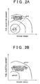
- FIGs. 2A and 2B are graphs each showing the relationship between the operating condition of the internal combustion engine 10 and the pH of the exhaust gas condensed water.
- the abscissa axis represents the rotational speed of the internal combustion engine 10
- the ordinate axis represents the fuel injection amount.
- FIG 2A shows the pH of the exhaust gas condensed water, which is exhibited when the catalyst is active (when the temperature of the catalyst 30 is relatively high). As shown in FIG 2A , the pH is low in the region in which the engine speed is high and the fuel injection amount is large.
- the pH of the exhaust gas condensed water indicates that the exhaust gas condensed water is strongly acidic (pH ⁇ 3), in other words, the intercooler 24 is more likely to corrode in the region in which the internal combustion engine 10 operates at high speed and high load. It is considered that the intercooler 24 is more likely to corrode because the nitrate ions NO 3 - described above are increased due to an increase of NOx in the exhaust gas.
- the pH of the exhaust gas condensed water varies depending on the operating condition of the internal combustion engine 10.
- FIG 2B shows the pH of the exhaust gas condensed water, which is exhibited when the catalyst is inactive (when the temperature of the catalyst 30 is relatively low).
- the pH of the exhaust gas condensed water is substantially constant even if the engine speed and the fuel injection amount change. That is, the corrosion environment of the intercooler 24 is substantially constant. More specifically, the pH of the exhaust gas condensed water indicates that the exhaust gas condensed water is strongly acidic (pH ⁇ 3) in the region in which the internal combustion engine 10 operates at low speed and low load.
- the pH of the exhaust gas condensed water is substantially constant independently of the operating condition of the internal combustion engine 10. It is considered that the pH of the exhaust gas condensed water, which is exhibited when the catalyst is inactive, is substantially constant due to presence of an acetate ion and a formic ion.
- the regions in which the bypass passage 27 is used will be described with reference to FIG 3 .
- the abscissa axis represents the rotational speed of the internal combustion engine 10, and the ordinate axis represents the fuel injection amount.
- the regions in which the bypass passage 27 is used are superimposed on the EGR modes.
- the EGR modes will be described below.
- the region "HPL” in FIG 3 only the high-pressure loop EGR unit 50 is used.
- the region “HPL + LPL” in FIG. 3 both the high-pressure loop EGR unit 50 and the low-pressure loop EGR unit 51 are used.
- the region “LPL” in FIG 3 only the low-pressure EGR unit 15 is used.
- the region “Non-EGR” in FIG. 3 neither the high-pressure loop EGR unit 50 nor the low-pressure loop EGR unit 51 is used.
- the pH of the exhaust gas condensed water indicates that the exhaust gas condensed water is strongly acidic (pH ⁇ 3) when the engine operating state is within the region in which the low-pressure loop EGR unit 51 is used, it is considered that the intercooler 24 is under the corrosion environment. Therefore, the condition that the engine operating state is within the region in which the low-pressure loop EGR unit 51 is used, and the condition that the exhaust gas is strongly acidic (pH ⁇ 3) are both satisfied, the bypass passage 27 is used (namely, the intake air flow toward the intercooler 24 is cut off to direct the intake air flow only to the bypass passage 27).
- the regions in which the above-mentioned conditions are both satisfied are the shaded regions A1 and A2.
- the regions in which the bypass passage 27 is used are the shaded regions A1 and A2. More specifically, the shaded region A1 corresponds to the region in which the bypass passage 27 is used when the catalyst is active, and the shaded region A2 corresponds to the region in which the bypass passage 27 is used when the catalyst is inactive.
- the shaded regions A1 and A2 roughly correspond to the regions, shown in FIGs. 2A and 2B , in which the exhaust gas condensed water is strongly acidic.
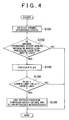
- FIG 4 is a flowchart showing the bypass control according to the first embodiment of the invention.
- the passage through which the intake air flows is selected between the intake passage 20 provided with the intercooler 24 and the bypass passage 27 through which the intake air flow bypasses the intercooler 24, based on the determination as to whether the intercooler 24 is under the corrosion environment.
- the routine of the control is periodically executed by the ECU 7 at predetermined time intervals.
- step S101 the ECU 7 detects the operating state of the internal combustion engine 10. More specifically, the ECU 7 determines the rotational speed of the internal combustion engine 10, the fuel injection amount, the intake air temperature, the amount of exhaust gas recirculated back to the internal combustion engine 10, the coolant temperature, etc. In this case, the ECU 7 receives detection signals S41, S42 and S43 from the intake air temperature sensor 41, the engine speed sensor 42 and the coolant temperature sensor 43, respectively.
- step S 102 is executed.
- step S102 the ECU 7 determines whether the engine operating state is within the region in which the low-pressure loop EGR unit 51 is used, based on the operating state of the internal combustion engine 10, which is detected in step S101. More specifically, the ECU 7 determines whether the engine operation state is within the region in which the low-pressure loop EGR unit 51 is used, based on the rotational speed of the internal combustion engine 10, the fuel injection amount, the coolant temperature, etc. For example, the ECU 7 determines whether the engine operating state is within the region in which the low-pressure loop EGR unit 51 is used, with reference to the map shown in FIG 3 . When the engine operating state is within the region in which the low-pressure loop EGR unit 51 is used ("YES" in step S102), step S103 is executed.
- the routine ends.
- the bypass passage 27 is not used.
- the ECU 7 controls the selector valve 26 in such a manner that the intake air flows through only the intake passage 20 provided with the intercooler 24.
- step S103 the ECU 7 calculates the pH of the exhaust gas condensed water based on the operating condition of the internal combustion engine 10, which is detected in step S101. More specifically, the ECU 7 calculates the pH of the exhaust gas condensed water based on the rotational speed of the internal combustion engine 10, the fuel injection amount, the temperature of the catalyst 30, etc. For example, the ECU 7 calculates the pH of the exhaust gas condensed water with reference to the map shown in FIG 2A or FIG 2B . In this case, the ECU 7 refers to the map in FIG 2A when the catalyst is active (when the temperature of the catalyst 30 is relatively high). When the catalyst is inactive (when the temperature of the catalyst 30 is relatively low), the ECU 7 refers to the map in FIG 2B . As the temperature of the catalyst 30, the ECU 7 may use a temperature detected by a sensor or an estimated temperature. When step S103 is completed, step S 104 is executed.
- step S104 the ECU 7 determines whether the pH of the exhaust gas condensed water is lower than the lower limit, or whether the pH of the exhaust gas condensed water is higher than the upper limit. In this case, the ECU 7 determines whether the pH of the exhaust gas condensed water is at a level at which the intercooler 24 will corrode. More specifically, the ECU 7 uses "3" as the lower limit, and "9" as the upper limit. Namely, the ECU 7 determines whether the pH of the exhaust gas condensed water is lower than three (pH ⁇ 3), or higher than nine (pH > 9).
- step S104 it is determined whether the pH of the exhaust gas condensed water is higher than nine (pH > 9) in order to reliably prevent corrosion of the intercooler 24.
- step S105 is executed.
- the ECU 7 selects the bypass passage 27 through which the intake air flow bypasses the intercooler 24 (step S105). Namely, the ECU 7 executes the control for cutting off the intake air flow toward the intercooler 24 to direct the intake air flow only to the bypass passage 27. In this case, the ECU 7 controls the selector valve 26 in such a manner that the intake air flow toward the intercooler 24 is cut off and the intake air flow through the bypass passage 27 is permitted.
- the routine ends.
- the pH of the exhaust gas condensed water is not at a level at which the intercooler 24 will corrode.
- the ECU 7 does not select the bypass passage 27 through which the intake air flow bypasses the intercooler 24.
- the ECU 7 executes the control for directing the intake air flow only to the intake passage 20 provided with the intercooler 24 and cutting off the intake air flow to the bypass passage 27.
- the ECU 7 controls the selector valve 26 in such a manner that the intake air flow is directed toward the intercooler 24 and the intake air flow to the bypass passage 27 is cut off.
- the second embodiment of the invention differs from the first embodiment of the invention in that the pH of the exhaust gas condensed water is detected by a sensor instead of estimating the pH of the exhaust gas condensed water. More specifically, according to the second embodiment of the invention, the pH of the exhaust gas condensed water is detected by a sensor that is provided to the intake passage 20, at a position upstream of the position at which the intercooler 24 is provided and downstream of the position to which the exhaust gas is recirculated back by the low-pressure loop EGR unit 51. Then, the ECU 7 determines whether the pH of the exhaust gas condensed water is at a level at which the intercooler 24 will corrode, based on the detected pH. After that, the ECU 7 executes the bypass control similar to that according to the first embodiment of the invention.
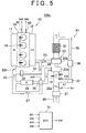
- FIG 5 is a block diagram schematically showing the structure of a control unit 100a for the internal combustion engine according to the second embodiment of the invention.
- the solid arrows indicate a flow of the intake air and a flow of the exhaust gas
- the dashed arrows indicate control signals and detection signals.
- the same reference numerals will be assigned to the components that are the same as those of the control unit 100 for the internal combustion engine according to the first embodiment of the invention.
- a pH sensor 45 is provided to the intake passage, at a position upstream of the position at which the intercooler 24 is provided and downstream of the position to which the exhaust gas is recirculated back by the low-pressure loop EGR unit 51. More specifically, the pH sensor 45 is provided to the intake passage 20, at a position downstream of the position to which the exhaust gas is recirculated back and upstream of the position at which the blow-by gas supply unit 19 is provided. The pH sensor 45 detects the pH of the exhaust gas condensed water, and transmits a detection signal S45 indicating the detected pH to an ECU 7a.
- the ECU 7a executes the bypass control by transmitting a control signal S26 to the selector valve 26, based on detection signals S41, S42, S43 and S45 transmitted from the intake air temperature sensor 41, the engine speed sensor 42, the coolant temperature sensor 43, and the pH sensor 45.
- the ECU 7a determines whether the pH of the exhaust gas condensed water is at a level at which the intercooler 24 will corrode, namely, whether the pH of the exhaust gas condensed water indicates that the exhaust gas condensed water is strongly acidic, based on the detected pH, and executes the bypass control.
- the ECU 7a executes the control for cutting off the intake air flow toward the intercooler 24 to direct the intake air flow only to the bypass passage 27.
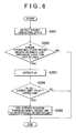
- FIG 6 is a flowchart showing the bypass control according to the second embodiment of the invention.
- the routine in the control is periodically executed by the ECU 7a at predetermined time internals. Because steps S201, S202, S204 and S205 (steps other than step S203) are the same as above-described steps S101, S102, S104 and S105, respectively, detailed description thereof will not be provided below. Only step S203 will be described below.
- step S203 the ECU 7a detects the pH of the exhaust gas condensed water. More specifically, the ECU 7a receives a detection signal S45 indicating the pH detected by the pH sensor 45. Then, the ECU 7a executes step S204. In step S204, the ECU 7a makes a determination in the manner as described above, based on the pH detected in step S203.
- Executing the bypass control according to the second embodiment of the invention also makes it possible to increase the corrosion resistance life of the intercooler 24 and to effectively suppress deterioration of the function and performance of the intercooler 24 due to corrosion.
- FIG 5 shows an example in which the pH sensor 45 is provided to the intake passage 20, at a position downstream of the position to which the exhaust gas is recirculated back and upstream of the position at which the blow-by gas supply unit 19 is provided.
- the position of the pH sensor 45 is not limited to this, as long as the pH sensor 45 is provided at a position upstream of the position at which the intercooler 24 is provided and downstream of the position to which the exhaust gas is recirculated back by the low-pressure loop EGR unit 51.
- the pH sensor 45 may be provided in the intercooler 24.
- the bypass control is executed based on the pH detected by the pH sensor 45.
- the parameter used for the bypass control is not limited to the pH of the exhaust gas condensed water.
- the bypass control may be executed using a NOx sensor that detects the NOx concentration instead of the pH sensor 45.
- the components of the exhaust gas are determined based on the value detected by the NOx sensor, whether the intercooler 24 is under the corrosion environment is determined based on the components of the exhaust gas, and the bypass control as described above is executed.
- the NOx sensor is provided to the exhaust passage 25 (for example, the exhaust passage 25 at a position downstream of the catalyst 30).
Abstract
Description
- The invention relates to a control apparatus for an internal combustion engine, which includes an exhaust gas recirculation passage through which exhaust gas is recirculated back from an exhaust passage to an intake passage, and a method for controlling the same.
- There has been suggested an exhaust gas recirculation (EGR) system for an internal combustion engine, for example, a diesel engine. The exhaust gas recirculation system recirculates a portion of exhaust gas back from an exhaust passage to an intake passage to decrease the combustion temperature in the engine, thereby suppressing generation of NOx. For example, an EGR system that recirculates exhaust gas back to an intake system from an exhaust passage at a portion downstream of a catalyst (hereinafter, referred to as a "low-pressure loop EGR system") has been suggested. Japanese Patent Application Publication No.
2005-146919 JP-A-2005-146919 - However, the technology described in
JP-A-2005-146919 - The invention provides a control apparatus for an internal combustion engine that executes a control for supplying an intake air to a bypass passage, through which an intake air flow bypasses an intercooler, based on the pH of the condensed water obtained from the exhaust gas, thereby ensuring reliability of the intercooler, and a method for controlling the control apparatus.
- A first aspect of the invention relates to a control apparatus for an internal combustion engine. The control apparatus includes: an exhaust gas recirculation unit that recirculates exhaust gas back from an exhaust passage, at a portion downstream of a turbine of a turbocharger and a catalyst, to an intake passage, at a portion upstream of a compressor of the turbocharger; an intercooler that is provided in the intake passage, at a position downstream of a position to which the exhaust gas is recirculated back by the exhaust gas recirculation unit; a bypass passage through which an intake air flow bypasses the intercooler; a pH determination unit that determines a pH of the condensed water obtained from the exhaust gas recirculated back by the exhaust gas recirculation unit by estimation or detection; a corrosion determination unit that determines whether the pH of the condensed water obtained from the exhaust gas is at a level at which the intercooler corrodes, based on the pH determined by the pH determination unit; and a bypass control unit that executes a control for cutting off an intake air flow toward the intercooler to direct the intake air flow only to the bypass passage, when the corrosion determination unit determines that the pH of the condensed water obtained from the exhaust gas is at the level at which the intercooler corrodes in a state where the exhaust gas is recirculated back by the exhaust gas recirculation unit.
- The control apparatus according to the first aspect of the invention is appropriately applied to, for example, a diesel engine provided with a turbocharger. The exhaust gas recirculation unit recirculates the exhaust gas back from the exhaust passage, at the portion downstream of the turbine of the turbocharger and the catalyst, to the intake passage, at the portion upstream of the compressor of the turbocharger. The intercooler is provided in the intake passage, at the position downstream of the position to which the exhaust gas is recirculated back by the exhaust gas recirculation system. The intercooler cools the gas that is supplied thereto. The intake air flow bypasses the intercooler through the bypass passage. The pH determination unit determines the pH of the condensed water obtained from the exhaust gas recirculated back by the exhaust gas recirculation unit by estimation or detection. The corrosion determination unit determines whether the pH of the condensed water obtained from the exhaust gas is at the level at which the intercooler corrodes. The bypass control unit executes the control for cutting off the flow of the intake air (fluid that contains not only the air take in from the outside of the vehicle but also the exhaust gas that is recirculated by exhaust gas recirculation unit and the condensed water obtained from the exhaust gas) toward the intercooler to direct the intake air flow only to the bypass passage, when the corrosion determination unit determines that the pH of the condensed water obtained from the exhaust gas is at the level at which the intercooler corrodes in the state where the exhaust gas is recirculated back by the exhaust gas recirculation unit. Thus, it is possible to appropriately prevent supply of strongly acidic exhaust gas condensed water to the intercooler. Namely, it is possible to appropriately prevent occurrence of corrosion environment under which the intercooler corrodes. Therefore, it is possible to increase the corrosion resistance life of the intercooler, and effectively suppress deterioration of the function and performance of the intercooler due to corrosion of the intercooler. In addition, it is no longer necessary to apply treatment for providing corrosion resistance to the intercooler. As a result, it is possible to ensure reliability of the intercooler.
- In the control apparatus according to the first aspect of the invention, the pH determination unit may estimate the pH of the condensed water obtained from the exhaust gas, based on at least one of the rotational speed of the internal combustion engine, the fuel injection amount, and the temperature of the catalyst. Thus, it is possible to accurately estimate the pH of the condensed water obtained from the exhaust gas.
- In the control apparatus according to the first aspect of the invention, the pH determination unit may detect the pH of the condensed water obtained from the exhaust gas using a sensor that is provided to the intake passage, at a position upstream of the position at which the intercooler is provided and downstream of the position to which the exhaust gas is recirculated back by the exhaust gas recirculation unit.
- Preferably, the bypass passage is defined by a member that is made of a material having a high corrosion resistance. Thus, it is possible to appropriately prevent occurrence of corrosion in the bypass passage, even when strongly acidic exhaust gas condensed water is supplied to the bypass passage.
- A second aspect of the invention relates to a method for controlling a control apparatus for an internal combustion engine. The control apparatus includes: an exhaust gas recirculation unit that recirculates exhaust gas back from an exhaust passage, at a portion downstream of a turbine of a turbocharger and a catalyst, to an intake passage, at a portion upstream of a compressor of the turbocharger; an intercooler that is provided in the intake passage, at a position downstream of a position to which the exhaust gas is recirculated back by the exhaust gas recirculation unit; and a bypass passage through which an intake air flow bypasses the intercooler. According to the method, a pH of the condensed water obtained from the exhaust gas recirculated back by the exhaust gas recirculation unit is determined by estimation or detection, and whether the pH of the condensed water obtained from the exhaust gas is at a level at which the intercooler corrodes is determined based on the determined pH. Then, a control for cutting off an intake air flow toward the intercooler to direct the intake air flow only to the bypass passage is executed, when it is determined that the pH of the condensed water obtained from the exhaust gas is at the level at which the intercooler corrodes in a state where the exhaust gas is recirculated back by the exhaust gas recirculation unit.
- The foregoing and further objects, features and advantages of the invention will become apparent from the following description of example embodiments with reference to the accompanying drawings, wherein the same or corresponding portions will be denoted by the same reference numerals and wherein:
-
FIG 1 is a block diagram schematically showing the structure of a control apparatus for an internal combustion engine according to a first embodiment of the invention; -
FIG 2A and FIG 2B are graphs each showing the relationship between the operating condition of the internal combustion engine and the pH of the condensed water obtained from the exhaust gas; -
FIG 3 is a graph illustrating the regions in which a bypass passage is used; -
FIG 4 is a flowchart of a bypass control according to the first embodiment of the invention; -
FIG 5 is a block diagram schematically showing the structure of a control apparatus for an internal combustion engine according to a second embodiment of the invention; and -
FIG. 6 is a flowchart of a bypass control according to the second embodiment of the invention. - Hereafter, embodiments of the invention will be described with reference to the accompanying drawings.
- First, a first embodiment of the invention will be described. Structure of apparatus
-
FIG 1 is a block diagram schematically showing the structure of acontrol apparatus 100 for an internal combustion engine according to the first embodiment of the invention. InFIG 1 , solid arrows indicate a flow of the intake air and a flow of the exhaust gas, and dashed arrows indicate control signals and detection signals. - The
control apparatus 100 inFIG 1 includes aninternal combustion engine 10 that is an in-line four-cylinder diesel engine. Each cylinder of theinternal combustion engine 10 is connected to anintake manifold 11 and anexhaust manifold 12. Theinternal combustion engine 10 hasfuel injection valves 15 provided to the respective cylinders, and a common-rail 14 that supplies high-pressure fuel to thefuel injection valves 15. The high-pressure fuel is supplied to the common-rail 14 by a fuel pump (not shown). Anengine speed sensor 42 detects the rotational speed of theinternal combustion engine 10, and transmits a detection signal S42 indicating the engine speed to anECU 7. Acoolant temperature sensor 43 detects the temperature of a coolant (hereinafter, referred to as "coolant temperature") that cools theinternal combustion engine 10, etc., and transmits a detection signal S43 indicating the coolant temperature to theECU 7. - An
intake passage 20 is connected to theintake manifold 11. Connected to theintake passage 20 are: anair cleaner 21 that purifies the air flowing into theinternal combustion engine 10; an intakeair temperature sensor 41 that detects the intake air temperature; athrottle valve 22a; a blow-bygas supply unit 19 that recirculates blow-by gas extracted from, for example, a crankcase back to an intake system; acompressor 23a of aturbocharger 23; an intercooler (IC) 24 that cools the intake air; and athrottle valve 22b. In addition, theintake passage 20 has abypass passage 27 through which the intake air flow bypasses theintercooler 24. In this case, thebypass passage 27 is connected to theintake passage 20 via aselector valve 26. Thebypass passage 27 is defined by a member made of a material having a high corrosion resistance (e.g. SUS). Theselector valve 26 is formed of, for example, a three-way valve. Theselector valve 26 selects the passage, through which the intake air flows, between theintake passage 20 provided with theintercooler 24 and thebypass passage 27 through which the intake air flow bypasses theintercooler 24. Theselector valve 26 is controlled according to a control signal S26 transmitted from theECU 7. The intakeair temperature sensor 41 transmits a signal S41 indicating the detected intake air temperature to theECU 7. - An
exhaust passage 25 connected to theexhaust manifold 12 is provided with aturbine 23b of theturbocharger 23 and acatalyst 30. Thecatalyst 30 is formed of, for example, an oxidation catalyst or a DPF (diesel particulate filter). - The
control apparatus 100 for an internal combustion engine includes anEGR unit 50 that recirculates a portion of the exhaust gas from theexhaust passage 25, at a portion upstream of theturbine 23b, to an intake passage, at a portion downstream of thecompressor 23a (hereinafter, referred to as "high-pressureloop EGR unit 50"), and anEGR unit 51 that recirculates a portion of the exhaust gas from the exhaust passage, at a portion downstream of theturbine 23b and thecatalyst 30, to the intake passage, at a portion upstream of thecompressor 23a (hereinafter, referred to as "low-pressureloop EGR unit 51 "). The high-pressureloop EGR unit 50 includes anEGR passage 31 and anEGR valve 33. TheEGR passage 31 provides communication between theexhaust passage 25, at a portion upstream of theturbine 23b, and theintake passage 20, at a portion downstream of theintercooler 24. TheEGR valve 33 that controls the amount of exhaust gas recirculated back to theinternal combustion engine 10 is provided in theEGR passage 31. The low-pressureloop EGR unit 51 includes anEGR passage 35, anEGR cooler 36, and anEGR valve 37. TheEGR passage 35 provides communication between theexhaust passage 25, at a portion downstream of thecatalyst 30, and theintake passage 20, at a portion upstream of thecompressor 23a. TheEGR cooler 36 that cools the EGR gas and theEGR valve 37 that controls the amount of EGR gas are provided in theEGR passage 35. - The components of the
control apparatus 100 are controlled by theECU 7. TheECU 7 is formed of a CPU (Central Processing Unit), ROM (Read Only Memory), RAM (Random Access Memory), etc. TheECU 7 transmits a control signal S26 to theselector valve 26 based mainly on detection signals S41, S42 and S43 from the intakeair temperature sensor 41, theengine speed sensor 42, and thecoolant temperature sensor 43, respectively. Namely, theECU 7 executes a control for selecting the passage, through which the intake air flows, between the passage provided with theintercooler 24 and thebypass passage 27 through which the intake air flow bypasses the intercooler 24 (hereinafter, referred to as "bypass control"). - According to the first embodiment of the invention, the
ECU 7 estimates the pH of the condensed water obtained from the exhaust gas that is recirculated by the low-pressureloop EGR unit 51. When it is determined that the pH of the condensed water is at a level at which theintercooler 24 will corrode, theECU 7 executes a control for cutting off the intake air flow toward theintercooler 24 to direct the intake air flow only to thebypass passage 27. As described above, theECU 7 corresponds to a pH determination unit, a corrosion determination unit, and a bypass control unit. Although theECU 7 executes controls over the other components of thecontrol apparatus 100, descriptions of the controls, which are not particularly related to the first embodiment of the invention, will not be provided below. - The first embodiment of the invention may be applied not only to the in-line four-cylinder
internal combustion engine 10 but also to an internal combustion engine having cylinders of which the number is other than four, or a V-engine in which two rows of cylinders are placed at a predetermined angle to each other. In addition, the first embodiment of the invention may be applied not only to theinternal combustion engine 10 having direct-injectionfuel injection valves 15 but also to an internal combustion engine having port-injection fuel injection valves. Bypass control method - Next, a bypass control method according to the first embodiment of the invention will be described in detail.
- According to the first embodiment of the invention, the
ECU 7 executes a bypass control so that the intake air is supplied to thebypass passage 27 through which the intake air flow bypasses theintercooler 24, when it is determined that theintercooler 24 is under the corrosion environment. More specifically, theECU 7 estimates the pH of the condensed water obtained from the exhaust gas that is recirculated back to theinternal combustion engine 10 by the low-pressureloop EGR unit 51. When it is determined that the pH of the condensed water is at a level at which theintercooler 24 will corrode, theECU 7 executes a control for cutting off the intake air flow toward theintercooler 24 to direct the intake air flow only to thebypass passage 27. In this specification, the term "intake air" signifies the fluid that may contain not only the air taken in from the outside of the vehicle but also the exhaust gas that is recirculated by the low-pressureloop EGR unit 51 and the condensed water obtained from the exhaust gas. - The bypass control is executed for the following reason. In the
internal combustion engine 10 including the low-pressureloop EGR unit 51, strongly acidic condensed water tends to be produced due to condensation of the exhaust gas (hereinafter, referred to as "exhaust gas condensed water" where appropriate). When such exhaust gas condensed water is introduced into the intake system and then supplied to theintercooler 24, theintercooler 24 may corrode because theintercooler 24 is usually made of, for example, aluminum. Corrosion of theintercooler 24 may affect the reliability of theintercooler 24. - Therefore, according to the first embodiment of the invention, the pH of the exhaust gas condensed water is estimated. Then, if the pH of the exhaust gas condensed water indicates that the exhaust gas condensed water is strongly acidic (for example, pH < 3), namely, when the
intercooler 24 is under the corrosion environment, the control for cutting off the intake air flow toward theintercooler 24 to direct the intake air flow only to thebypass passage 27 is executed. According to the bypass control method described above, it is possible to increase the corrosion resistance life of theintercooler 24, and to effectively suppress deterioration of the function and performance of theintercooler 24 due to corrosion. In addition, it is possible to prevent occurrence of the situation in which the exhaust gas condensed water is produced due to condensation of the exhaust gas in theintercooler 24 and theintercooler 24 is corroded by the exhaust gas condensed water. Because thebypass passage 27 is defined by the member made of a material having a high corrosion resistance, the possibility that the member that forms thebypass passage 27 will corrode is considerably low. - Next, the method for estimating the pH of the exhaust gas condensed water according to the first embodiment of the invention will be described. The pH of the exhaust gas condensed water tends to change depending on the combustion condition (e.g. NOx concentration), the catalyst state, the gas temperature, the fuel property, etc. Namely, the pH of the exhaust gas condensed water is influenced by the components of exhaust gas and a catalyst reaction, and varies depending on the degree to which the
internal combustion engine 10 has been warmed. It is considered that the pH of the exhaust gas condensed water is correlated with NO3, SO4, an acetate ion, and a formic ion. More specifically, the pH of the exhaust gas condensed water is expressed by Equation 1).
The characters "a" to "d" in Equation 1) correspond to the degrees of influence of the respective ions. For example, "a ≈ 1", "b = 0.037", "c = 0.008", and "d = 2". Thus, the pH of the exhaust gas condensed water is significantly influenced by [NO3 -] and [SO4 2-]. Here, [NO3 -] is influenced by the combustion condition (load condition) in theinternal combustion engine 10, and [SO4 2-] is influenced by the fuel property. - Based on the facts described above, it is considered that the pH of the exhaust gas condensed water indicates that the exhaust gas condensed water is strongly acidic in the high NOx concentration region in which the
internal combustion engine 10 operates at high speed and high load or the catalyst inactivate condition under which theinternal combustion engine 10 operates at low speed and low load. Therefore, according to the first embodiment of the invention, theECU 7 estimates the pH of the exhaust gas condensed water based on the operating condition of the internal combustion engine 10 (for example, engine speed, fuel injection amount and temperature of the catalyst 30). -
FIGs. 2A and 2B are graphs each showing the relationship between the operating condition of theinternal combustion engine 10 and the pH of the exhaust gas condensed water. In each ofFIGS. 2A and 2B , the abscissa axis represents the rotational speed of theinternal combustion engine 10, and the ordinate axis represents the fuel injection amount.FIG 2A shows the pH of the exhaust gas condensed water, which is exhibited when the catalyst is active (when the temperature of thecatalyst 30 is relatively high). As shown inFIG 2A , the pH is low in the region in which the engine speed is high and the fuel injection amount is large. Namely, the pH of the exhaust gas condensed water indicates that the exhaust gas condensed water is strongly acidic (pH < 3), in other words, theintercooler 24 is more likely to corrode in the region in which theinternal combustion engine 10 operates at high speed and high load. It is considered that theintercooler 24 is more likely to corrode because the nitrate ions NO3 - described above are increased due to an increase of NOx in the exhaust gas. As described above, when the catalyst is active, the pH of the exhaust gas condensed water varies depending on the operating condition of theinternal combustion engine 10. -
FIG 2B shows the pH of the exhaust gas condensed water, which is exhibited when the catalyst is inactive (when the temperature of thecatalyst 30 is relatively low). As shown inFIG 2B , the pH of the exhaust gas condensed water is substantially constant even if the engine speed and the fuel injection amount change. That is, the corrosion environment of theintercooler 24 is substantially constant. More specifically, the pH of the exhaust gas condensed water indicates that the exhaust gas condensed water is strongly acidic (pH < 3) in the region in which theinternal combustion engine 10 operates at low speed and low load. As described above, when the catalyst is inactive, the pH of the exhaust gas condensed water is substantially constant independently of the operating condition of theinternal combustion engine 10. It is considered that the pH of the exhaust gas condensed water, which is exhibited when the catalyst is inactive, is substantially constant due to presence of an acetate ion and a formic ion. - Next, the regions in which the
bypass passage 27 is used will be described with reference toFIG 3 . InFIG 3 , the abscissa axis represents the rotational speed of theinternal combustion engine 10, and the ordinate axis represents the fuel injection amount. The regions in which thebypass passage 27 is used are superimposed on the EGR modes. The EGR modes will be described below. In the region "HPL" inFIG 3 , only the high-pressureloop EGR unit 50 is used. In the region "HPL + LPL" inFIG. 3 , both the high-pressureloop EGR unit 50 and the low-pressureloop EGR unit 51 are used. In the region "LPL" inFIG 3 , only the low-pressure EGR unit 15 is used. In the region "Non-EGR" inFIG. 3 , neither the high-pressureloop EGR unit 50 nor the low-pressureloop EGR unit 51 is used. - In the first embodiment of the invention, if the pH of the exhaust gas condensed water indicates that the exhaust gas condensed water is strongly acidic (pH < 3) when the engine operating state is within the region in which the low-pressure
loop EGR unit 51 is used, it is considered that theintercooler 24 is under the corrosion environment. Therefore, the condition that the engine operating state is within the region in which the low-pressureloop EGR unit 51 is used, and the condition that the exhaust gas is strongly acidic (pH < 3) are both satisfied, thebypass passage 27 is used (namely, the intake air flow toward theintercooler 24 is cut off to direct the intake air flow only to the bypass passage 27). InFIG 3 , the regions in which the above-mentioned conditions are both satisfied are the shaded regions A1 and A2. That is, the regions in which thebypass passage 27 is used are the shaded regions A1 and A2. More specifically, the shaded region A1 corresponds to the region in which thebypass passage 27 is used when the catalyst is active, and the shaded region A2 corresponds to the region in which thebypass passage 27 is used when the catalyst is inactive. The shaded regions A1 and A2 roughly correspond to the regions, shown inFIGs. 2A and 2B , in which the exhaust gas condensed water is strongly acidic. - Next, the routine executed in the above-mentioned bypass control will be described with reference to
FIG 4. FIG 4 is a flowchart showing the bypass control according to the first embodiment of the invention. In the bypass control, the passage through which the intake air flows is selected between theintake passage 20 provided with theintercooler 24 and thebypass passage 27 through which the intake air flow bypasses theintercooler 24, based on the determination as to whether theintercooler 24 is under the corrosion environment. The routine of the control is periodically executed by theECU 7 at predetermined time intervals. - First, in step S101, the
ECU 7 detects the operating state of theinternal combustion engine 10. More specifically, theECU 7 determines the rotational speed of theinternal combustion engine 10, the fuel injection amount, the intake air temperature, the amount of exhaust gas recirculated back to theinternal combustion engine 10, the coolant temperature, etc. In this case, theECU 7 receives detection signals S41, S42 and S43 from the intakeair temperature sensor 41, theengine speed sensor 42 and thecoolant temperature sensor 43, respectively. After step S101 is completed, step S 102 is executed. - In step S102, the
ECU 7 determines whether the engine operating state is within the region in which the low-pressureloop EGR unit 51 is used, based on the operating state of theinternal combustion engine 10, which is detected in step S101. More specifically, theECU 7 determines whether the engine operation state is within the region in which the low-pressureloop EGR unit 51 is used, based on the rotational speed of theinternal combustion engine 10, the fuel injection amount, the coolant temperature, etc. For example, theECU 7 determines whether the engine operating state is within the region in which the low-pressureloop EGR unit 51 is used, with reference to the map shown inFIG 3 . When the engine operating state is within the region in which the low-pressureloop EGR unit 51 is used ("YES" in step S102), step S103 is executed. On the other hand, when the engine operating state is not within the region in which the low-pressureloop EGR unit 51 is used ("NO" in step S102), the routine ends. In this case, thebypass passage 27 is not used. Namely, theECU 7 controls theselector valve 26 in such a manner that the intake air flows through only theintake passage 20 provided with theintercooler 24. - In step S103, the
ECU 7 calculates the pH of the exhaust gas condensed water based on the operating condition of theinternal combustion engine 10, which is detected in step S101. More specifically, theECU 7 calculates the pH of the exhaust gas condensed water based on the rotational speed of theinternal combustion engine 10, the fuel injection amount, the temperature of thecatalyst 30, etc. For example, theECU 7 calculates the pH of the exhaust gas condensed water with reference to the map shown inFIG 2A or FIG 2B . In this case, theECU 7 refers to the map inFIG 2A when the catalyst is active (when the temperature of thecatalyst 30 is relatively high). When the catalyst is inactive (when the temperature of thecatalyst 30 is relatively low), theECU 7 refers to the map inFIG 2B . As the temperature of thecatalyst 30, theECU 7 may use a temperature detected by a sensor or an estimated temperature. When step S103 is completed, step S 104 is executed. - In step S104, the
ECU 7 determines whether the pH of the exhaust gas condensed water is lower than the lower limit, or whether the pH of the exhaust gas condensed water is higher than the upper limit. In this case, theECU 7 determines whether the pH of the exhaust gas condensed water is at a level at which theintercooler 24 will corrode. More specifically, theECU 7 uses "3" as the lower limit, and "9" as the upper limit. Namely, theECU 7 determines whether the pH of the exhaust gas condensed water is lower than three (pH < 3), or higher than nine (pH > 9). Whether the exhaust gas condensed water is higher than nine (pH > 9) is determined, because aluminum that forms theintercooler 24 will be corroded by the exhaust gas condensed water having an alkali level of "ph > 9" in some cases. Namely, in step S104, it is determined whether the pH of the exhaust gas condensed water is higher than nine (pH > 9) in order to reliably prevent corrosion of theintercooler 24. - When the pH of the exhaust gas condensed water is lower than the lower limit, or when the pH of the exhaust gas condensed water is higher than the upper limit ("YES" in step S104), more specifically, when the pH is lower than three (pH < 3) or when the pH is higher than nine (pH > 9), step S105 is executed. In this case, because the pH of the exhaust gas condensed water is at a level at which the
intercooler 24 will corrode, theECU 7 selects thebypass passage 27 through which the intake air flow bypasses the intercooler 24 (step S105). Namely, theECU 7 executes the control for cutting off the intake air flow toward theintercooler 24 to direct the intake air flow only to thebypass passage 27. In this case, theECU 7 controls theselector valve 26 in such a manner that the intake air flow toward theintercooler 24 is cut off and the intake air flow through thebypass passage 27 is permitted. When step S 105 is completed, the routine ends. - On the other hand, when the pH of the exhaust gas condensed water is equal to or higher than the lower limit and equal to or lower than the upper limit ("NO" in step S104), more specifically, when the pH of the exhaust gas condensed water is equal to or higher than three and equal to or lower than 9 (3 ≤ pH ≤ 9), the routine ends. In this case, the pH of the exhaust gas condensed water is not at a level at which the
intercooler 24 will corrode. Namely, theECU 7 does not select thebypass passage 27 through which the intake air flow bypasses theintercooler 24. In other words, theECU 7 executes the control for directing the intake air flow only to theintake passage 20 provided with theintercooler 24 and cutting off the intake air flow to thebypass passage 27. In this case, theECU 7 controls theselector valve 26 in such a manner that the intake air flow is directed toward theintercooler 24 and the intake air flow to thebypass passage 27 is cut off. - According to the bypass control described above, it is possible to appropriately prevent supply of strongly acidic exhaust gas condensed water to the
intercooler 24. Namely, it is possible to appropriately prevent occurrence of corrosion environment under which theintercooler 24 will corrode. Therefore, it is possible to increase the corrosion resistance life of theintercooler 24, and effectively suppress deterioration of the function and performance of theintercooler 24 due to corrosion. As a result, it is possible to ensure reliability of theintercooler 24. In addition, it is no longer necessary to apply treatment for providing corrosion resistance to theintercooler 24. - Next, a second embodiment of the invention will be described. The second embodiment of the invention differs from the first embodiment of the invention in that the pH of the exhaust gas condensed water is detected by a sensor instead of estimating the pH of the exhaust gas condensed water. More specifically, according to the second embodiment of the invention, the pH of the exhaust gas condensed water is detected by a sensor that is provided to the
intake passage 20, at a position upstream of the position at which theintercooler 24 is provided and downstream of the position to which the exhaust gas is recirculated back by the low-pressureloop EGR unit 51. Then, theECU 7 determines whether the pH of the exhaust gas condensed water is at a level at which theintercooler 24 will corrode, based on the detected pH. After that, theECU 7 executes the bypass control similar to that according to the first embodiment of the invention. -
FIG 5 is a block diagram schematically showing the structure of acontrol unit 100a for the internal combustion engine according to the second embodiment of the invention. InFIG. 5 , the solid arrows indicate a flow of the intake air and a flow of the exhaust gas, and the dashed arrows indicate control signals and detection signals. The same reference numerals will be assigned to the components that are the same as those of thecontrol unit 100 for the internal combustion engine according to the first embodiment of the invention. - In the
control unit 100a, apH sensor 45 is provided to the intake passage, at a position upstream of the position at which theintercooler 24 is provided and downstream of the position to which the exhaust gas is recirculated back by the low-pressureloop EGR unit 51. More specifically, thepH sensor 45 is provided to theintake passage 20, at a position downstream of the position to which the exhaust gas is recirculated back and upstream of the position at which the blow-bygas supply unit 19 is provided. ThepH sensor 45 detects the pH of the exhaust gas condensed water, and transmits a detection signal S45 indicating the detected pH to anECU 7a. - The
ECU 7a executes the bypass control by transmitting a control signal S26 to theselector valve 26, based on detection signals S41, S42, S43 and S45 transmitted from the intakeair temperature sensor 41, theengine speed sensor 42, thecoolant temperature sensor 43, and thepH sensor 45. According to the second embodiment of the invention, theECU 7a determines whether the pH of the exhaust gas condensed water is at a level at which theintercooler 24 will corrode, namely, whether the pH of the exhaust gas condensed water indicates that the exhaust gas condensed water is strongly acidic, based on the detected pH, and executes the bypass control. More specifically, when it is determined that the pH of the exhaust gas condensed water is at a level at which theintercooler 24 will corrode (for example, pH < 3), theECU 7a executes the control for cutting off the intake air flow toward theintercooler 24 to direct the intake air flow only to thebypass passage 27. -
FIG 6 is a flowchart showing the bypass control according to the second embodiment of the invention. The routine in the control is periodically executed by theECU 7a at predetermined time internals. Because steps S201, S202, S204 and S205 (steps other than step S203) are the same as above-described steps S101, S102, S104 and S105, respectively, detailed description thereof will not be provided below. Only step S203 will be described below. - In step S203, the
ECU 7a detects the pH of the exhaust gas condensed water. More specifically, theECU 7a receives a detection signal S45 indicating the pH detected by thepH sensor 45. Then, theECU 7a executes step S204. In step S204, theECU 7a makes a determination in the manner as described above, based on the pH detected in step S203. - Executing the bypass control according to the second embodiment of the invention also makes it possible to increase the corrosion resistance life of the
intercooler 24 and to effectively suppress deterioration of the function and performance of theintercooler 24 due to corrosion. -
FIG 5 shows an example in which thepH sensor 45 is provided to theintake passage 20, at a position downstream of the position to which the exhaust gas is recirculated back and upstream of the position at which the blow-bygas supply unit 19 is provided. However, the position of thepH sensor 45 is not limited to this, as long as thepH sensor 45 is provided at a position upstream of the position at which theintercooler 24 is provided and downstream of the position to which the exhaust gas is recirculated back by the low-pressureloop EGR unit 51. Alternatively, thepH sensor 45 may be provided in theintercooler 24. - In the second embodiment of the invention described above, the bypass control is executed based on the pH detected by the
pH sensor 45. However, the parameter used for the bypass control is not limited to the pH of the exhaust gas condensed water. For example, the bypass control may be executed using a NOx sensor that detects the NOx concentration instead of thepH sensor 45. In this case, the components of the exhaust gas are determined based on the value detected by the NOx sensor, whether theintercooler 24 is under the corrosion environment is determined based on the components of the exhaust gas, and the bypass control as described above is executed. The NOx sensor is provided to the exhaust passage 25 (for example, theexhaust passage 25 at a position downstream of the catalyst 30).
Claims (12)
- A control apparatus (100) for an internal combustion engine (10), comprising:an exhaust gas recirculation unit (51) that recirculates exhaust gas back from an exhaust passage (25), at a portion downstream of a turbine (23b) of a turbocharger (23) and a catalyst (30), to an intake passage (20), at a portion upstream of a compressor (23a) of the turbocharger (23);an intercooler (24) that is provided in the intake passage (20), at a position downstream of a position to which the exhaust gas is recirculated back by the exhaust gas recirculation unit (51);a bypass passage (27) through which an intake air flow bypasses the intercooler (24); characterized by :a pH determination unit (7) that determines a pH of condensed water obtained from the exhaust gas recirculated back by the exhaust gas recirculation unit (51) by estimation or detection;a corrosion determination unit (7) that determines whether the pH of the condensed water obtained from the exhaust gas is at a level at which the intercooler (24) corrodes, based on the pH determined by the pH determination unit (7); anda bypass control unit (7) that executes a control for cutting off an intake air flow toward the intercooler (24) to direct the intake air flow only to the bypass passage (27), when the corrosion determination unit (7) determines that the pH of the condensed water obtained from the exhaust gas is at the level at which the intercooler (24) corrodes in a state where the exhaust gas is recirculated back by the exhaust gas recirculation unit (51).
- The control apparatus according to claim 1, wherein the pH determination unit (7) estimates the pH of the condensed water obtained from the exhaust gas, based on at least one of a rotational speed of the internal combustion engine (10), a fuel injection amount, and a temperature of the catalyst (30).
- The control apparatus according to claim 1, wherein the pH determination unit (7) detects the pH of the condensed water obtained from the exhaust gas using a sensor (45) that is provided to the intake passage (20), at a position upstream of the position at which the intercooler (24) is provided and downstream of the position to which the exhaust gas is recirculated back by the exhaust gas recirculation unit (51).
- The control apparatus according to any one of claims 1 to 3, wherein the bypass passage (27) is defined by a member that is made of a material having a high corrosion resistance.
- The control apparatus according to any one of claims 1 to 4, wherein it is determined that the pH of the condensed water obtained from the exhaust gas is at the level at which the intercooler (24) corrodes, when a pH value of the condensed water obtained from the exhaust gas is lower than three.
- The control apparatus according to any one of claims 1 to 4, wherein it is determined that the pH of the condensed water obtained from the exhaust gas is at the level at which the intercooler (24) corrodes, when a pH value of the condensed water obtained from the exhaust gas is higher than nine.
- A method for controlling a control apparatus (100) for an internal combustion engine (10), the control apparatus including:an exhaust gas recirculation unit (51) that recirculates exhaust gas back from an exhaust passage (25), at a portion downstream of a turbine (23b) of a turbocharger (23) and a catalyst (30), to an intake passage (20), at a portion upstream of a compressor (23a) of the turbocharger (23);an intercooler (24) that is provided in the intake passage (20), at a position downstream of a position to which the exhaust gas is recirculated back by the exhaust gas recirculation unit (51); anda bypass passage (27) through which an intake air flow bypasses the intercooler (24),the method characterized by comprising:determining a pH of condensed water obtained from the exhaust gas recirculated back by the exhaust gas recirculation unit (51) by estimation or detection;determining whether the pH of the condensed water obtained from the exhaust gas is at a level at which the intercooler (24) corrodes, based on the determined pH; andexecuting a control for cutting off an intake air flow toward the intercooler (24) to direct the intake air How only to the bypass passage (27), when it is determined that the pH of the condensed water obtained from the exhaust gas is at the level at which the intercooler (24) corrodes in a state where the exhaust gas is recirculated back by the exhaust gas recirculation unit (51).
- The method according to claim 7, wherein the pH of the condensed water obtained from the exhaust gas is estimated based on at least one of a rotational speed of the internal combustion engine (20), a fuel injection amount, and a temperature of the catalyst (30).
- The method according to claim 7, wherein the pH of the condensed water obtained from the exhaust gas is detected using a sensor (45) that is provided to the intake passage (20), at a position upstream of the position at which the intercooler (24) is provided and downstream of the position to which the exhaust gas is recirculated back by the exhaust gas recirculation unit (51).
- The method according to any one of claims 7 to 9, wherein the bypass passage (27) is defined by a member that is made of a material having a high corrosion resistance.
- The method according to any one of claims 7 to 10, wherein it is determined that the pH of the condensed water obtained from the exhaust gas is at the level at which the intercooler (24) corrodes, when a pH value of the condensed water obtained from the exhaust gas is lower than three.
- The method according to any one of claims 7 to 10, wherein it is determined that the pH of the condensed water obtained from the exhaust gas is at the level at which the intercooler (24) corrodes, when a pH value of the condensed water obtained from the exhaust gas is higher than nine.
Applications Claiming Priority (2)
| Application Number | Priority Date | Filing Date | Title |
|---|---|---|---|
| JP2007031872A JP4483873B2 (en) | 2007-02-13 | 2007-02-13 | Control device for internal combustion engine |
| PCT/IB2008/000258 WO2008099248A1 (en) | 2007-02-13 | 2008-02-05 | Control apparatus for internal combustion engine and method for controlling the same |
Publications (2)
| Publication Number | Publication Date |
|---|---|
| EP2111504A1 EP2111504A1 (en) | 2009-10-28 |
| EP2111504B1 true EP2111504B1 (en) | 2010-11-03 |
Family
ID=39469538
Family Applications (1)
| Application Number | Title | Priority Date | Filing Date |
|---|---|---|---|
| EP08709770A Expired - Fee Related EP2111504B1 (en) | 2007-02-13 | 2008-02-05 | Control apparatus for internal combustion engine and method for controlling the same |
Country Status (5)
| Country | Link |
|---|---|
| US (1) | US8051659B2 (en) |
| EP (1) | EP2111504B1 (en) |
| JP (1) | JP4483873B2 (en) |
| DE (1) | DE602008003303D1 (en) |
| WO (1) | WO2008099248A1 (en) |
Cited By (1)
| Publication number | Priority date | Publication date | Assignee | Title |
|---|---|---|---|---|
| DE102015203473A1 (en) * | 2015-02-26 | 2016-09-01 | Ford Global Technologies, Llc | Cleaning an intercooler in a system with exhaust gas recirculation |
Families Citing this family (33)
| Publication number | Priority date | Publication date | Assignee | Title |
|---|---|---|---|---|
| JP4225322B2 (en) * | 2006-01-27 | 2009-02-18 | トヨタ自動車株式会社 | Exhaust gas recirculation device for internal combustion engine |
| WO2008145502A1 (en) * | 2007-05-29 | 2008-12-04 | Mahle International Gmbh | Charge air valve system for use in an internal combustion engine |
| JP5136309B2 (en) * | 2008-09-10 | 2013-02-06 | いすゞ自動車株式会社 | Engine system |
| DE102008049625A1 (en) * | 2008-09-30 | 2010-04-08 | Mann + Hummel Gmbh | Apparatus and method for neutralizing acid condensate in a motor vehicle |
| JP5262992B2 (en) * | 2009-05-22 | 2013-08-14 | トヨタ自動車株式会社 | Control device for internal combustion engine |
| US20110041483A1 (en) * | 2009-08-21 | 2011-02-24 | Caterpillar Inc. | Method of controlling fuel in an exhaust treatment system implementing temporary engine control |
| US8056339B2 (en) * | 2010-01-08 | 2011-11-15 | Ford Global Technologies, Llc | Warming intake air using EGR cooler in dual-throttle boosted engine system |
| WO2011161980A1 (en) * | 2010-06-22 | 2011-12-29 | 本田技研工業株式会社 | Control apparatus for internal combustion engine |
| JP5682245B2 (en) * | 2010-11-10 | 2015-03-11 | 株式会社Ihi | Low pressure loop EGR device |
| KR101283144B1 (en) | 2011-05-04 | 2013-07-05 | 기아자동차주식회사 | Exhaust Gas Humidity Control Method and Exhaust Gas Recirculation System thereof |
| JP2012255404A (en) * | 2011-06-09 | 2012-12-27 | Toyota Motor Corp | Engine system |
| FR2986565B1 (en) * | 2012-02-06 | 2014-01-24 | Renault Sa | METHOD AND SYSTEM FOR DIAGNOSING THE INTAKE OF AIR IN AN INTERNAL COMBUSTION ENGINE OF A MOTOR VEHICLE |
| JP5874817B2 (en) * | 2012-04-12 | 2016-03-02 | トヨタ自動車株式会社 | Internal combustion engine flow control device |
| JP5999324B2 (en) * | 2012-06-22 | 2016-09-28 | 三菱自動車工業株式会社 | Intake system structure of internal combustion engine |
| US9145823B2 (en) * | 2012-10-19 | 2015-09-29 | Ford Global Technologies, Llc | Method for purging condensate from a charge air cooler |
| US9151222B2 (en) | 2012-12-12 | 2015-10-06 | Caterpillar Inc. | Six-stroke combustion cycle engine and process |
| US8978602B2 (en) | 2012-12-12 | 2015-03-17 | Caterpillar Inc. | Six-stroke engine power density matching system and method |
| US8978601B2 (en) | 2012-12-12 | 2015-03-17 | Caterpillar Inc. | Six-stroke engine system with blowdown exhaust system |
| US8978603B2 (en) | 2012-12-12 | 2015-03-17 | Caterpillar Inc. | Six-stroke internal combustion engine valve activation system and method for operating such engine |
| US9181830B2 (en) | 2012-12-12 | 2015-11-10 | Caterpillar Inc. | After-treatment system and method for six-stroke combustion cycle |
| US9133764B2 (en) | 2012-12-12 | 2015-09-15 | Caterpillar Inc. | Six-stroke engine system with blowdown exhaust recirculation |
| US9057324B2 (en) | 2012-12-12 | 2015-06-16 | Caterpillar Inc. | Six-stroke engine system with blowdown turbocharger |
| CN105308277B (en) * | 2013-06-28 | 2018-04-10 | 丰田自动车株式会社 | The condensed water treating device of internal combustion engine |
| US9255518B2 (en) * | 2013-10-24 | 2016-02-09 | Norfolk Southern Corporation | System and method for an aftercooler bypass |
| JP6075271B2 (en) * | 2013-11-12 | 2017-02-08 | トヨタ自動車株式会社 | Control device for internal combustion engine |
| JP6213322B2 (en) * | 2014-03-18 | 2017-10-18 | トヨタ自動車株式会社 | Internal combustion engine |
| ITUB20152487A1 (en) * | 2015-07-24 | 2017-01-24 | Magneti Marelli Spa | METHOD FOR CHECKING THE MASS CAPACITY OF AN EGR RECIRCULATION CIRCUIT FOR LOW-PRESSURE EXHAUST GASES OF A SUPER-POWERED INTERNAL COMBUSTION ENGINE |
| US10794336B2 (en) * | 2016-04-14 | 2020-10-06 | Ford Global Technologies, Llc | Methods and systems for an exhaust gas recirculation cooler |
| JP6648719B2 (en) * | 2017-02-27 | 2020-02-14 | トヨタ自動車株式会社 | Control device for internal combustion engine |
| JP6734221B2 (en) * | 2017-04-28 | 2020-08-05 | トヨタ自動車株式会社 | Control device for internal combustion engine |
| JP7029348B2 (en) * | 2018-05-11 | 2022-03-03 | 株式会社Soken | Engine control system |
| JP7052707B2 (en) * | 2018-12-18 | 2022-04-12 | トヨタ自動車株式会社 | Internal combustion engine control system |
| CN110748442A (en) * | 2019-09-27 | 2020-02-04 | 同济大学 | Throttle-free air inlet system of spark ignition engine and power control method |
Family Cites Families (14)
| Publication number | Priority date | Publication date | Assignee | Title |
|---|---|---|---|---|
| JPS4845009U (en) * | 1971-10-01 | 1973-06-12 | ||
| JP3341087B2 (en) * | 1993-03-02 | 2002-11-05 | マツダ株式会社 | Exhaust recirculation system for turbocharged engines |
| JP3538892B2 (en) | 1994-05-31 | 2004-06-14 | マツダ株式会社 | Engine exhaust recirculation system |
| JPH0814111A (en) | 1994-06-24 | 1996-01-16 | Isuzu Motors Ltd | Egr device of supercharged diesel engine with intercooler |
| JP3329123B2 (en) | 1995-02-28 | 2002-09-30 | 日産自動車株式会社 | Diesel engine intake temperature control system |
| JPH09256915A (en) | 1996-03-19 | 1997-09-30 | Isuzu Motors Ltd | Egr device for diesel engine with intercooler |
| US6301887B1 (en) * | 2000-05-26 | 2001-10-16 | Engelhard Corporation | Low pressure EGR system for diesel engines |
| US6422219B1 (en) * | 2000-11-28 | 2002-07-23 | Detroit Diesel Corporation | Electronic controlled engine exhaust treatment system to reduce NOx emissions |
| US6367256B1 (en) * | 2001-03-26 | 2002-04-09 | Detroit Diesel Corporation | Exhaust gas recirculation with condensation control |
| US6725847B2 (en) * | 2002-04-10 | 2004-04-27 | Cummins, Inc. | Condensation protection AECD for an internal combustion engine employing cooled EGR |
| US6934621B2 (en) * | 2003-07-25 | 2005-08-23 | Detroit Diesel Corporation | Re-entry strategy from boost mode to EGR mode |
| JP4029827B2 (en) | 2003-11-12 | 2008-01-09 | トヨタ自動車株式会社 | Exhaust gas recirculation device for internal combustion engine |
| FR2876416B1 (en) * | 2004-10-11 | 2007-01-26 | Renault Sas | SUPERCHARGED INTERNAL COMBUSTION ENGINE HAVING A RECIRCULATION CIRCUIT FOR BURNED GASES |
| WO2006126993A1 (en) * | 2005-05-24 | 2006-11-30 | Honeywell International Inc. | Turbocharger compressor having improved erosion-corrosion resistance |
-
2007
- 2007-02-13 JP JP2007031872A patent/JP4483873B2/en not_active Expired - Fee Related
-
2008
- 2008-02-05 WO PCT/IB2008/000258 patent/WO2008099248A1/en active Application Filing
- 2008-02-05 US US12/373,351 patent/US8051659B2/en not_active Expired - Fee Related
- 2008-02-05 DE DE602008003303T patent/DE602008003303D1/en active Active
- 2008-02-05 EP EP08709770A patent/EP2111504B1/en not_active Expired - Fee Related
Cited By (3)
| Publication number | Priority date | Publication date | Assignee | Title |
|---|---|---|---|---|
| DE102015203473A1 (en) * | 2015-02-26 | 2016-09-01 | Ford Global Technologies, Llc | Cleaning an intercooler in a system with exhaust gas recirculation |
| US9945331B2 (en) | 2015-02-26 | 2018-04-17 | Ford Global Technologies, Llc | Cleaning of a charge-air cooler in a system with exhaust gas recirculation arrangement |
| DE102015203473B4 (en) * | 2015-02-26 | 2020-03-26 | Ford Global Technologies, Llc | Cleaning an intercooler in an exhaust gas recirculation system |
Also Published As
| Publication number | Publication date |
|---|---|
| WO2008099248A1 (en) | 2008-08-21 |
| DE602008003303D1 (en) | 2010-12-16 |
| JP4483873B2 (en) | 2010-06-16 |
| US20090308071A1 (en) | 2009-12-17 |
| EP2111504A1 (en) | 2009-10-28 |
| US8051659B2 (en) | 2011-11-08 |
| JP2008196368A (en) | 2008-08-28 |
Similar Documents
| Publication | Publication Date | Title |
|---|---|---|
| EP2111504B1 (en) | Control apparatus for internal combustion engine and method for controlling the same | |
| RU2623321C1 (en) | Fault diagnostic unit for exhaust gas extraction control device | |
| US8392098B2 (en) | Abnormality diagnosis device of internal combustion engine | |
| US8783014B2 (en) | Control system for internal combustion engine | |
| EP3179087B1 (en) | Error determination unit | |
| US8857161B2 (en) | Exhaust gas purification apparatus and exhaust gas purification method for an internal combustion engine | |
| US7931015B2 (en) | Method and apparatus for controlling diesel engine | |
| EP2284369B1 (en) | Diagnosis apparatus for reducing agent supply apparatus | |
| EP2562406B1 (en) | Abnormality detection device and abnormality detection method for egr system | |
| JP4720820B2 (en) | Abnormality diagnosis device for exhaust gas recirculation system | |
| US8919102B2 (en) | Exhaust purifying device for internal combustion engines | |
| EP2196646B1 (en) | Exhaust gas purification system for an internal combustion engine | |
| JP2009047130A (en) | Control device for internal combustion engine | |
| EP2546506B1 (en) | Control device for internal combustion engine | |
| JP4765866B2 (en) | Control device for internal combustion engine | |
| US7770382B2 (en) | Secondary air supply system and abnormality detection method for secondary air supply system | |
| JP7346250B2 (en) | Internal combustion engine system abnormality diagnosis device | |
| US20240011429A1 (en) | Control device for internal combustion engine | |
| JP2017129027A (en) | Control system of compression self-ignition type internal combustion engine | |
| EP2905440B1 (en) | Reducing agent supply device | |
| JP2012219772A (en) | Rotation speed control device of internal combustion engine | |
| JP2010203425A (en) | Control device of internal combustion engine |
Legal Events
| Date | Code | Title | Description |
|---|---|---|---|
| PUAI | Public reference made under article 153(3) epc to a published international application that has entered the european phase |
Free format text: ORIGINAL CODE: 0009012 |
|
| 17P | Request for examination filed |
Effective date: 20090331 |
|
| AK | Designated contracting states |
Kind code of ref document: A1 Designated state(s): DE FR |
|
| GRAP | Despatch of communication of intention to grant a patent |
Free format text: ORIGINAL CODE: EPIDOSNIGR1 |
|
| DAX | Request for extension of the european patent (deleted) | ||
| GRAS | Grant fee paid |
Free format text: ORIGINAL CODE: EPIDOSNIGR3 |
|
| GRAA | (expected) grant |
Free format text: ORIGINAL CODE: 0009210 |
|
| AK | Designated contracting states |
Kind code of ref document: B1 Designated state(s): DE FR |
|
| REF | Corresponds to: |
Ref document number: 602008003303 Country of ref document: DE Date of ref document: 20101216 Kind code of ref document: P |
|
| PLBE | No opposition filed within time limit |
Free format text: ORIGINAL CODE: 0009261 |
|
| STAA | Information on the status of an ep patent application or granted ep patent |
Free format text: STATUS: NO OPPOSITION FILED WITHIN TIME LIMIT |
|
| 26N | No opposition filed |
Effective date: 20110804 |
|
| REG | Reference to a national code |
Ref country code: DE Ref legal event code: R097 Ref document number: 602008003303 Country of ref document: DE Effective date: 20110804 |
|
| REG | Reference to a national code |
Ref country code: DE Ref legal event code: R084 Ref document number: 602008003303 Country of ref document: DE Effective date: 20121115 |
|
| PGFP | Annual fee paid to national office [announced via postgrant information from national office to epo] |
Ref country code: DE Payment date: 20130131 Year of fee payment: 6 Ref country code: FR Payment date: 20130301 Year of fee payment: 6 |
|
| REG | Reference to a national code |
Ref country code: DE Ref legal event code: R119 Ref document number: 602008003303 Country of ref document: DE |
|
| REG | Reference to a national code |
Ref country code: FR Ref legal event code: ST Effective date: 20141031 |
|
| REG | Reference to a national code |
Ref country code: DE Ref legal event code: R119 Ref document number: 602008003303 Country of ref document: DE Effective date: 20140902 |
|
| PG25 | Lapsed in a contracting state [announced via postgrant information from national office to epo] |
Ref country code: FR Free format text: LAPSE BECAUSE OF NON-PAYMENT OF DUE FEES Effective date: 20140228 Ref country code: DE Free format text: LAPSE BECAUSE OF NON-PAYMENT OF DUE FEES Effective date: 20140902 |