EP2111210B1 - Break seal before access dual chamber bag - Google Patents
Break seal before access dual chamber bag Download PDFInfo
- Publication number
- EP2111210B1 EP2111210B1 EP07868881.9A EP07868881A EP2111210B1 EP 2111210 B1 EP2111210 B1 EP 2111210B1 EP 07868881 A EP07868881 A EP 07868881A EP 2111210 B1 EP2111210 B1 EP 2111210B1
- Authority
- EP
- European Patent Office
- Prior art keywords
- enclosure
- seal
- bag
- medical fluid
- frangible seal
- Prior art date
- Legal status (The legal status is an assumption and is not a legal conclusion. Google has not performed a legal analysis and makes no representation as to the accuracy of the status listed.)
- Not-in-force
Links
Images


Classifications
-
- A—HUMAN NECESSITIES
- A61—MEDICAL OR VETERINARY SCIENCE; HYGIENE
- A61J—CONTAINERS SPECIALLY ADAPTED FOR MEDICAL OR PHARMACEUTICAL PURPOSES; DEVICES OR METHODS SPECIALLY ADAPTED FOR BRINGING PHARMACEUTICAL PRODUCTS INTO PARTICULAR PHYSICAL OR ADMINISTERING FORMS; DEVICES FOR ADMINISTERING FOOD OR MEDICINES ORALLY; BABY COMFORTERS; DEVICES FOR RECEIVING SPITTLE
- A61J1/00—Containers specially adapted for medical or pharmaceutical purposes
- A61J1/14—Details; Accessories therefor
- A61J1/20—Arrangements for transferring or mixing fluids, e.g. from vial to syringe
- A61J1/2093—Containers having several compartments for products to be mixed
-
- A—HUMAN NECESSITIES
- A61—MEDICAL OR VETERINARY SCIENCE; HYGIENE
- A61M—DEVICES FOR INTRODUCING MEDIA INTO, OR ONTO, THE BODY; DEVICES FOR TRANSDUCING BODY MEDIA OR FOR TAKING MEDIA FROM THE BODY; DEVICES FOR PRODUCING OR ENDING SLEEP OR STUPOR
- A61M1/00—Suction or pumping devices for medical purposes; Devices for carrying-off, for treatment of, or for carrying-over, body-liquids; Drainage systems
- A61M1/14—Dialysis systems; Artificial kidneys; Blood oxygenators ; Reciprocating systems for treatment of body fluids, e.g. single needle systems for hemofiltration or pheresis
- A61M1/16—Dialysis systems; Artificial kidneys; Blood oxygenators ; Reciprocating systems for treatment of body fluids, e.g. single needle systems for hemofiltration or pheresis with membranes
- A61M1/1654—Dialysates therefor
- A61M1/1656—Apparatus for preparing dialysates
- A61M1/1668—Details of containers
- A61M1/167—Flexible packaging for solid concentrates
-
- A—HUMAN NECESSITIES
- A61—MEDICAL OR VETERINARY SCIENCE; HYGIENE
- A61J—CONTAINERS SPECIALLY ADAPTED FOR MEDICAL OR PHARMACEUTICAL PURPOSES; DEVICES OR METHODS SPECIALLY ADAPTED FOR BRINGING PHARMACEUTICAL PRODUCTS INTO PARTICULAR PHYSICAL OR ADMINISTERING FORMS; DEVICES FOR ADMINISTERING FOOD OR MEDICINES ORALLY; BABY COMFORTERS; DEVICES FOR RECEIVING SPITTLE
- A61J1/00—Containers specially adapted for medical or pharmaceutical purposes
- A61J1/05—Containers specially adapted for medical or pharmaceutical purposes for collecting, storing or administering blood, plasma or medical fluids ; Infusion or perfusion containers
- A61J1/10—Bag-type containers
-
- A—HUMAN NECESSITIES
- A61—MEDICAL OR VETERINARY SCIENCE; HYGIENE
- A61J—CONTAINERS SPECIALLY ADAPTED FOR MEDICAL OR PHARMACEUTICAL PURPOSES; DEVICES OR METHODS SPECIALLY ADAPTED FOR BRINGING PHARMACEUTICAL PRODUCTS INTO PARTICULAR PHYSICAL OR ADMINISTERING FORMS; DEVICES FOR ADMINISTERING FOOD OR MEDICINES ORALLY; BABY COMFORTERS; DEVICES FOR RECEIVING SPITTLE
- A61J1/00—Containers specially adapted for medical or pharmaceutical purposes
- A61J1/14—Details; Accessories therefor
- A61J1/20—Arrangements for transferring or mixing fluids, e.g. from vial to syringe
- A61J1/2003—Accessories used in combination with means for transfer or mixing of fluids, e.g. for activating fluid flow, separating fluids, filtering fluid or venting
- A61J1/202—Separating means
- A61J1/2024—Separating means having peelable seals
Definitions
- the present disclosure relates to medical fluid solution bags and more particularly to dual chamber solution bags.
- dialysate Peritoneal dialysis solution
- Dialysate has traditionally included lactate in a single chamber bag.
- dialysate has been made to be bicarbonate based.
- Bicarbonate is unstable in the presence of magnesium and calcium and forms a precipitate after a period of time. Accordingly, bicarbonate based dialysate needs to be packaged in a dual chamber supply bag.
- the two chambers of the dual chamber bag are separated by a seal that a person breaks without tearing the entire bag.
- a seal provided by the assignee of the present disclosure is termed a peel seal.
- the patient or caregiver breaks the seal between the two chambers and the solution from the two chambers is mixed and used before a calcium or magnesium precipitate can form.
- Fig. 1 illustrates a known dual chamber bag 10.
- a medical fluid system such as a peritoneal dialysis system, is connected to bag 10 via an access system 20.
- Access system 20 is connected fluidly to chamber 12.
- frangible seal 14 is broken allowing solution A residing within chamber 16 to mix with solution B residing within chamber 12.
- bag 10 presents an inherent risk. If after connecting the bag 10 to the patient, the seal between chamber 12 and access system 20 is broken before frangible seal 14 is broken (allowing solutions A and B to mix), a potentially physiologically unsafe solution B is allowed to reach the patient or to contact the patient's blood.
- EP-A-1,693,043 discloses a dual chamber container which is folded. The chambers can be opened to mix the contents by unfolding the container.
- WO 99/20222 discloses a dispensing device comprising a container body which is partitioned into two compartments, one containing water and the other a powder, by a diaphragm. The diaphragm can be broken to mix the contents which can then be dispensed via a dispensing opening leading from one of the compartments.
- the dual chamber bags described herein can be used for different medical fluid therapies.
- the dual chamber bag is a peritoneal dialysate bag.
- the dual chamber bag stores dialysate used for hemodialysis, such as home hemodialysis.
- dialysate used for hemodialysis
- home hemodialysis the interest in home hemodialysis is increasing. Patients would typically rather have hemodialysis performed at home than in a center. In certain areas of the country, hemodialysis centers are located remotely, requiring a long drive or other transport on top of the time needed for the therapy itself. Farther, performing treatment while the patient is relaxing or even sleeping lessens the interruption of the patient's active day. Bagged dialysate is also used for in-center hemodialysis treatments.
- the dual chamber bags described herein are also useful for substitution or replacement fluids, for example, for hemofiltration or hemodiafiltration, wherein it is again desirable to keep multiple solutions separate prior to use.
- Described herein are dual chamber bags and processes for making the same, wherein in general, the frangible or peel seal needs to be broken before or in order to make a connection between the patient and the access system of the bag.
- Illustrated below are multiple embodiments for embedding the access system or access port within the bag.
- the access port or access system can be embedded entirely within one or both of the chambers.
- a handle is provided that allows the user to pull the access system from within the dual chamber bag to make it available to be connected to a patient.
- the handle and the access port are connected to an intermediate or force transfer device that is in turn connected or part of the frangible or peel seal.
- the intermediate device can be a cord, string, ribbon, monofilament or sheet of plastic.
- the plastic or film for example can be the same as that used to make the dual chamber bag.
- the intermediate or force transfer device is configured to withstand a force larger than that needed to break the frangible seal.
- the intermediate device is also configured to be part of or integrated with the peel seal. That is, it is formed with the seal used to separate the dual chambers from each other.
- the dual chamber bags can have one or a plurality of frangible seals.
- the seals can be located perpendicular to or parallel to a direction of the access port.
- one seal can be used to separate the two chambers, while a second seal separates the access system from the rest of the bag.
- the access port is buried within the bag, isolating it from the patient until the main seal is broken.
- the bag in certain embodiments is folded multiple times to achieve a desired configuration relative to the access system. During the folding process, the force transfer or intermediate device linking the handle with the seal is applied, e.g., welded, to the bag.
- one or more sides or seams of the bags are welded, e.g., sonically; via heat seal and/or chemically welded.
- the folds and the welds result in a dual chamber bag that partially or completely embeds the access system until the main peel seal separating the two chambers is broken.
- Fig. 1 is an elevation view of a prior art dual chamber bag.
- Figs. 2 to 5A are elevation views illustrating one dual chamber bag and method of making same according to the present disclosure.
- Fig. 5B is an alternative dual chamber bag to the one shown in connection with Fig. 5A .
- Figs. 6 to 9 are elevation views illustrating another dual chamber bag and method of making same according to the present disclosure.
- Fig. 10 is an elevation view of an alternative embodiment of the dual chamber bag of Fig. 9 .
- FIG. 11A to 11C , 12A, 12R, 13A, 13B 14A. 14B, 15A, 15B , 16A. 16B, 17A, 17B , 18A, 18B, 19A, 19B , 20A and 20B illustrate a further alternative dual chamber bag and method of making same according to the present disclosure.
- Figs. 21 to 23 illustrate yet another alternative dual chamber bag and method of making same according to the present disclosure.
- Figs. 24 to 26 illustrate still another alternative dual chamber bag and method of making same according to the present disclosure.
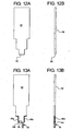
- FIG. 2 illustrates a first manufacturing figure for dual chamber bag 30.
- an overall enclosure 32 is formed by folding a piece of material for enclosure 32 along fold line 34.
- the material for enclosure 32 and indeed for each of the enclosures discussed herein is any one or more of polyvinyl chloride (“PVC”), Japanese polyolefinic container (“JPOC”), propylene/ethylene copolymer (“cPP”), polypropylene (“PP”), polyamide (“PA”) and combinations thereof.
- PVC polyvinyl chloride
- JPOC Japanese polyolefinic container
- cPP propylene/ethylene copolymer
- PP polypropylene
- PA polyamide
- a string or pull handle 40 is welded into a portion of seams 38a and 38b, such that a first portion 40a of string 40 resides outside of enclosure 32, while a second portion 40b of string 40 is looped inside enclosure 32.
- Suitable material for string 40 includes any of the materials listed above.
- Inner portion 40b can be welded to seams 38a and 38b after such seams have been formed. Alternatively, inner portion 40b of string 40 is welded with seams 38a and 38b to form enclosure 32.
- Access system 50 is welded to enclosure 32 at welded seam 42, which is located distally from folded seam 34.
- Access system 50 includes a connector 52 that connects to a line leading to a disposable cassette used with a medical fluid machine, such as a peritoneal dialysis, hemodialysis, hemofiltration or other type or renal failure therapy device.
- the line is a solution line of a manual peritoneal dialysis therapy or continuous ambulatory peritoneal dialysis ("CAPD”) treatment.
- Access system 50 also includes a seal 54, which blocks solution from existing access system 50 until a connection is made with connector 52.
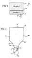
- Fig. 3 the process for embedding access system 50 within enclosure 32 is begun.
- distal seam 42 is pushed vertically upwards towards folded seam 34, causing welded seams 38a and 38b to buckle, such that a continuous or annular groove 44 begins to form between an outer portion 46 of seams 38a and 38b and an inner portion 48 of those seams.
- Fig. 4 illustrates access system 50 embedded completely within enclosure 32.
- Access system 50 is now surrounded completely by continuous groove or opening 44 created by pushing distal seam 42 connected to access system 50 towards folded line 34. It should be noted that even though access system 50 is embedded with enclosure 32, access system 50 remains external to the enclosure. Only portion 40b of string 40 is actually inside enclosure 32.
- FIG. 5A one embodiment of a completed dual chamber bag according to the principals of the present disclosure is illustrated by bag 30.
- a peel seal 56a is made to separate enclosure 32 into first fluid chamber 58a and second fluid chamber 58b.
- One suitable apparatus and method for forming the peel seal or frangible seal 56a is set forth in U.S. Patent No. 6,319,243 , entitled, "Containers and Methods for Storing and Admixing Medical Solutions", assigned to the eventual assignee of the present application, the entire contents of which are incorporated herein expressly by reference and relied upon.
- inner portion 40b of string or handle 40 is embedded within and extends through peel seal 56a.
- inner portion 40b is configured and positioned to tear peel seal 56a and allow a first fluid residing within first fluid chamber 58a to mix with a second fluid residing within a second fluid chamber 58b.
- Access system 50 is relatively inaccessible to the patient or caregiver before that person pulls string or handle 40 to tear frangible seal 56a and expose access system 50. It is possible however that if someone labored hard enough, they could locate access system 50 within the folds creating opening 44 and puncture seal 54 before pulling string or handle 40. Accordingly, and optionally, a second frangible seal 56b is provided at the open end of opening 44, which seals that open end until handle 40 is pulled, tearing second frangible seal 56b.
- second peel seal 56b can be fixed or fastened to handle 40, such that it is carried with handle 40 as exposed section 40a of handle 40 is pulled. As seen in Fig. 5B , second frangible seal 56b does not have to fully close the open end of opening 44 but merely make reaching access system 50 impossible or at least highly improbable and impractical.
- Dual chamber bag 30 of Fig. 5B is like dual chamber bag 30 of Figs. 1 to 5A in all respect except that inner portion 40b of handle 40 includes multiple string loops or is otherwise expanded such that when exposed portion 40a of handle or string 40 is pulled, the multiple loops or expanded version of inner portion 40b tears open a larger portion of peel seal 56a, increasing the ability of first and second fluids located within first and second chambers 58a and 58b to mix properly and efficiently.
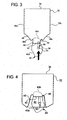
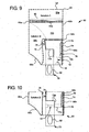
- FIG. 9 a second primary embodiment of the dual chamber solution bag according to the present disclosure is illustrated by bag 60 ( Fig. 9 ).
- Figs. 6 to 8 show various stages of manufacturer of bag 60.
- Fig. 9 shows one embodiment for completed bag 60.
- Fig. 10 shows another embodiment for dual chamber bag 60.
- bag 60 and bag 30 of Figs. 5A and 5B One primary difference between bag 60 and bag 30 of Figs. 5A and 5B is that the pull string of bag 30 is replaced by handle 70, which in the illustrated embodiment is a piece of plastic film or sheeting, such as the same sheeting used to form enclosure 62. Enclosure 62 also has a different shape than enclosure 32 of bag 30. Another primary difference for dual chamber bag 60 is that enclosure 62 is folded at the bottom of the bag, near handle 70, and is welded at opposing upper seam 64. As seen in Figs. 6 to 9 , sheet handle 70 includes an outer pull portion 70a, which resides outside chamber 62, and which defines an aperture 82 sized for example to accept a finger or fingers of the patient or caregiver. Handle 70 also expands in size at an inner portion 70b, which is maintained within enclosure 62. The larger portion 70b is sized to open all or most all of a frangible or peel seal when the patient or caregiver grasps and pulls handle 80.
- handle 70 which in the illustrated
- Fig. 7 illustrates that enclosure 62 is formed by folding the enclosure at fold line 72a, such that upper seam 64, and side seams 66a, 66b, 68a and 68b can be welded via any of the embodiments discussed herein. Also, enclosure 62 is welded at seams 72b and 72c discussed in further detail below. Fig. 7 further illustrates how sheeting handle 70 is integrated into enclosure 62, namely, it is inserted near the bottom of enclosure 62, so that a curved edge 84 of handle 70 comes into substantial alignment with curved seam 68a of enclosure 62.
- Fig. 8 illustrates a sealed enclosure 62 prior to the enclosure being folded into itself to protect against inadvertent breaking of seal 54 of access system 50.
- handle 70 is sealed within enclosure 62, such that portion 70b resides within enclosure 72 and portion 70a remains outside of enclosure 72.
- Enclosure 62 is welded at seams 64, 66a, 66b, 68a, 68b and 72b.
- the upper end of enclosed portion 70b of handle 70 expands at an area where a first frangible or peel seal is made as seen in Fig. 9 .
- Seal 68b does not include the side of the portion 70b of handle 70. That is, sides of enclosure 62 are welded together to form 68b. Likewise, seal 68a does not include edge 84 of handle 70. Seal 72b however does include handle 70. In this manner, enclosure 62 at seal 72b moves with handle 70 as handle 70 is grasped and pulled, which in turn moves inner portion 70b of handle 70 relative to seals 68a and 68b.
- Fig. 9 shows a completed dual chamber bag 60.
- enclosure 62 is folded within itself to form inner opening 74, which includes a continuous opening around an inner opening wall 78 and outer opening wall 76 of enclosure 62.
- Enclosure 62 is folded into itself until access system 50 is hidden within enclosure 62.
- First and second frangible seals 56a and 56b are then applied to enclosure 62.
- Frangible seal 56a seals sheets of enclosure 62 and an upper end 80 of handle 70. Upper end 80 spans substantially all of the width of enclosure 62, such that seal 56a opens a large area for solution A housed in first chamber 88a to mix properly and readily with solution B maintained within chamber 88b. As illustrated, frangible seal 56a separates chamber 88a from chamber 88b.
- a second frangible seal 56b is provided to separate solution B of chamber 88b from an access area and from reaching access system 50.
- inner portion 70b tears through frangible seals 56a and 56b virtually simultaneously, so that solutions A and B mix and also so that the mixed solution reaches seal 54 of access system 50 for the first time.
- portion 70b is welded with seams 68a and 68b, and seal 56b is broken by applying pressure to the outside of enclosure 62 after frangible seal 56a is broken.
- FIG. 9 illustrates an alternative embodiment for dual chamber bag 60, in which access system 50 is rotated ninety degrees with respect to its position in bag 60 of Fig. 9 .
- access system 50 is very difficult to locate and open until handle 70 is pulled and both frangible seals 56a and 56b are broken.
- the configuration of access system 50 in Fig. 10 adds another layer of security and safety to dual chamber bag 60.
- FIG. 11A to 11C a yet further alternative dual chamber bag of the present disclosure and method of making same is illustrated by bag 90 ( Figs. 20A and 20B ).
- Figs. 11A to 11C show three different configurations for enclosure 92 of dual chamber bag 90.
- Fig. 11A illustrates an enclosure 92 having a stepped shaped bottom.
- Fig. 11B illustrates enclosure 92 having a triangular shaped bottom.
- Fig. 11C illustrates enclosure 92 having a rounded bottom.
- stepped shaped bottom of Fig. 11 A is shown in the remaining figures. It should be appreciated however that the teachings shown in the remaining figures are applicable to any of the configurations of enclosure 92 of Figs. 11A to 11C and to other suitable shapes that may be readily formed by those of skill in the art.
- Figs. 12A and 12B show that the first step in the manufacturer of dual chamber bag 90 is to fold enclosure 92 at fold line 94.
- Figs. 13A and 13B illustrate that the next step includes the formation of welded seams 96a and 96b along a portion of the sides of enclosure 92.
- access system 50 is welded to enclosure 92 at fold line 94.
- a handle 100 such as a loop or tab, is welded to the outside of enclosure 92.
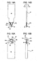
- Figs. 14A and 14B illustrate the addition of the first frangible seal 56a, which separates access system 50 from the remainder of enclosure 92. Air is maintained between frangible seal 56a and access system 50.
- Figs. 15A and 15B illustrate a second folding operation resulting in second fold lines 98 and the creation of channel 102 between the access system 50 and handle 100 area and the outer sheets of enclosure 92.
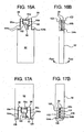
- FIGs. 16A and 16B another step in the manufacturer of dual chamber bag 90 is the addition of welded seams 104a and 104b, which further enclose chamber 102.
- Fig. 16B shows how weld 104b is made around inner weld 96b.
- Figs. 17A and 17B illustrate a third folding operation, in which fold lines 106 are created by folding enclosure 92 at a portion of weld seams 104a and 104b. The additional fold creates an outer chamber 108, which surrounds inner chamber 102.
- Figs. 18A and 18B illustrate the addition of outer welds 110a, 110b and 112. Outer welds seal outer chamber 108 completely.
- Figs.19A and 19D illustrate the addition of the second peel seal or frangible seal 56b.
- the second frangible seal 56b is made to divide outer chamber 108 into first fluid holding chamber 114a and second fluid holding chamber 114b as seen best in Fig: 19B .
- Frangible seal 56a seals access system 50 from chamber 114a as seen in Fig.19B .
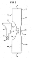
- Figs. 20A and 20B illustrate dual chamber bag 90 in further detail.
- Fig. 19B is a section view of Fig. 19A taken along line XX-XX shown in Fig. 19A .
- Fig. 20B shows the general shape of first chamber 114a and second chamber 114b. It also shows that frangible seals 56a and 56b are aligned and overlapping.
- Second chamber 114b is an annular or continuous chamber in which a second solution is trapped between outer and inner cylindrical or continuous walls. Second chamber 114b surrounds an empty space in which access system 50 and handle 100 are located.
- frangible seal 56b between chambers 114a and 114b is subjected to a force almost perpendicular to the walls of container 90, due to the folding of film of enclosure 92.
- frangible seal 56a in the inner layers does not experience any stress during this action since the two inner most layers move together in the same direction.
- frangible seal 56a separating chambers 114a and 114b breaks before inner frangible seal 56a, guaranteeing that mixing takes place before any liquid can reach seal 54 of access system 50.
- frangible seal 56b is broken by applying pressure to the mixed open chambers, such that the increased pressure of the liquid causes frangible seal 56a to open and fluid to flow to access system 50.
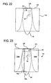
- Figs. 21 to 23 illustrate still a further alternative dual chamber bag 120 and method of making same, which includes the provision of a vertical frangible seal after access system 50 is pushed as far as it can go into enclosure 122.
- Fig. 22 shows that enclosure 122 at access system 50 is pushed into itself until that portion meets upper distal wall 124 of enclosure 122.
- String 40 in enclosure 120 is maintained wholly outside of enclosure 122 and indeed can be welded to the outside of enclosure 122.
- Access system 50 is welded at seam 126 to upper edge 124 of enclosure 122.
- Fig. 23 illustrates that upper and lower frangible seals 56a and 56b (located one on top of the other) separate and form first and second chambers 128a and 128b.
- access system 50 is pulled through both upper and lower frangible seals 56a and 56b, allowing first and second fluids in first and second chambers 128a and 128b, respectively, to mix.
- weld 126 seals first and second chambers 128a and 128b from access system 50, such that no fluid can be transferred to the patient.
- Figs. 24 to 26 illustrate another vertical frangible seal embodiment.
- This embodiment includes three frangible seals 56a, 56b and 56c.
- Dual chamber container 130 includes an enclosure 132 formed in much the same way as is enclosure 92 of container 90 discussed above.
- first seal 56a forms a safety seal between enclosure 132 and access system 50.
- frangible seat 56a isolates access system 50 from enclosure 132.
- Vertical peel seals 56b and 56c as seen in Figs. 24 and 26 separate enclosure 132 into first and second fluid carrying chambers 134a and 134b.
- the user pulls handle or cord 40, which is completely external to chamber 132 to rip an upper inner edge 135 of enclosure 132 through frangible seals 56b and 56c, allowing fluid from first and second chambers 134a and 134b to mix.
- container 130 can be opened readily for example by hanging cord 40 around a door handle and allowing enclosure 132, holding first and second fluids to drop hangman style to automatically mix the first and second fluids.
- access system 50 points vertically upward (imagine container 130 in Fig. 25 turned upside down), such that the weight of fluid will not place any pressure on safety frangible seal 56a. The user can then squeeze dual chamber container 130 to pop or open frangible seal 56a.
Landscapes
- Health & Medical Sciences (AREA)
- Heart & Thoracic Surgery (AREA)
- Urology & Nephrology (AREA)
- Life Sciences & Earth Sciences (AREA)
- Animal Behavior & Ethology (AREA)
- General Health & Medical Sciences (AREA)
- Public Health (AREA)
- Veterinary Medicine (AREA)
- Emergency Medicine (AREA)
- Vascular Medicine (AREA)
- Engineering & Computer Science (AREA)
- Anesthesiology (AREA)
- Biomedical Technology (AREA)
- Hematology (AREA)
- Pharmacology & Pharmacy (AREA)
- Medical Preparation Storing Or Oral Administration Devices (AREA)
- External Artificial Organs (AREA)
- Bag Frames (AREA)
Description
- The present disclosure relates to medical fluid solution bags and more particularly to dual chamber solution bags.
- Various medical treatments, such as peritoneal dialysis, use dual bag solutions. Peritoneal dialysis solution is called dialysate. Dialysate has traditionally included lactate in a single chamber bag. More recently, dialysate has been made to be bicarbonate based. Bicarbonate is unstable in the presence of magnesium and calcium and forms a precipitate after a period of time. Accordingly, bicarbonate based dialysate needs to be packaged in a dual chamber supply bag.
- The two chambers of the dual chamber bag are separated by a seal that a person breaks without tearing the entire bag. One such seal provided by the assignee of the present disclosure is termed a peel seal. Prior to use, the patient or caregiver breaks the seal between the two chambers and the solution from the two chambers is mixed and used before a calcium or magnesium precipitate can form.
- The two unmixed solutions separated by the peel seal pose a risk. Each solution taken individually is physiologically unsafe for the patient. Accordingly, it is necessary to properly mix the individual solutions to form the final solution before injecting any of the solutions into the patient or contacting any of the solutions with the patient's blood.
-
Fig. 1 illustrates a knowndual chamber bag 10. A medical fluid system, such as a peritoneal dialysis system, is connected tobag 10 via anaccess system 20.Access system 20 is connected fluidly tochamber 12. When it is desired to use the combined solution withinbag 10, afrangible seal 14 is broken allowing solution A residing withinchamber 16 to mix with solution B residing withinchamber 12. - As alluded to above,
bag 10 presents an inherent risk. If after connecting thebag 10 to the patient, the seal betweenchamber 12 andaccess system 20 is broken beforefrangible seal 14 is broken (allowing solutions A and B to mix), a potentially physiologically unsafe solution B is allowed to reach the patient or to contact the patient's blood. -
EP-A-1,693,043 discloses a dual chamber container which is folded. The chambers can be opened to mix the contents by unfolding the container. -
WO 99/20222 - Accordingly, an improved dual chamber solution bag is needed.
- According to the present invention there is provided a multiple chamber medical fluid bag according to
claim 1. - The dual chamber bags described herein can be used for different medical fluid therapies. In one embodiment, the dual chamber bag is a peritoneal dialysate bag. In another embodiment, the dual chamber bag stores dialysate used for hemodialysis, such as home hemodialysis. Here, the interest in home hemodialysis is increasing. Patients would typically rather have hemodialysis performed at home than in a center. In certain areas of the country, hemodialysis centers are located remotely, requiring a long drive or other transport on top of the time needed for the therapy itself. Farther, performing treatment while the patient is relaxing or even sleeping lessens the interruption of the patient's active day. Bagged dialysate is also used for in-center hemodialysis treatments. The dual chamber bags described herein are also useful for substitution or replacement fluids, for example, for hemofiltration or hemodiafiltration, wherein it is again desirable to keep multiple solutions separate prior to use.
- Described herein are dual chamber bags and processes for making the same, wherein in general, the frangible or peel seal needs to be broken before or in order to make a connection between the patient and the access system of the bag. Illustrated below are multiple embodiments for embedding the access system or access port within the bag. For example, the access port or access system can be embedded entirely within one or both of the chambers.
- In each embodiment, a handle is provided that allows the user to pull the access system from within the dual chamber bag to make it available to be connected to a patient. The handle and the access port are connected to an intermediate or force transfer device that is in turn connected or part of the frangible or peel seal. For example, the intermediate device can be a cord, string, ribbon, monofilament or sheet of plastic. The plastic or film for example can be the same as that used to make the dual chamber bag. The intermediate or force transfer device is configured to withstand a force larger than that needed to break the frangible seal. The intermediate device is also configured to be part of or integrated with the peel seal. That is, it is formed with the seal used to separate the dual chambers from each other.
- As seen herein, the dual chamber bags can have one or a plurality of frangible seals. The seals can be located perpendicular to or parallel to a direction of the access port. For example one seal can be used to separate the two chambers, while a second seal separates the access system from the rest of the bag.
- As seen below, the access port is buried within the bag, isolating it from the patient until the main seal is broken. The bag in certain embodiments is folded multiple times to achieve a desired configuration relative to the access system. During the folding process, the force transfer or intermediate device linking the handle with the seal is applied, e.g., welded, to the bag.
- As further seen below, one or more sides or seams of the bags are welded, e.g., sonically; via heat seal and/or chemically welded. The folds and the welds result in a dual chamber bag that partially or completely embeds the access system until the main peel seal separating the two chambers is broken.
- It is therefore an advantage of the present disclosure to provide a dual chamber medical fluid bag having increased safety.
- It is another advantage of the present disclosure to provide a dual chamber bag in which a frangible seal separating first and second individual solutions needs to be broken before an access system allowing access to the dual chamber bag can be reached and connected to the patient.
- It is a further advantage of the present disclosure to provide a dual chamber bag that is relatively easy to form.
- It is another advantage of the present disclosure to provide a dual chamber bag that is made of relatively inexpensive components.
- Additional features and advantages are described herein, and will be apparent from, the following Detailed Description and the figures.
-
Fig. 1 is an elevation view of a prior art dual chamber bag. -
Figs. 2 to 5A are elevation views illustrating one dual chamber bag and method of making same according to the present disclosure. -
Fig. 5B is an alternative dual chamber bag to the one shown in connection withFig. 5A . -
Figs. 6 to 9 are elevation views illustrating another dual chamber bag and method of making same according to the present disclosure. -
Fig. 10 is an elevation view of an alternative embodiment of the dual chamber bag ofFig. 9 . -
Figs. 11A to 11C ,12A, 12R, 13A, 13B 14A. 14B, 15A, 15B ,16A. 16B, 17A, 17B ,18A, 18B, 19A, 19B ,20A and 20B illustrate a further alternative dual chamber bag and method of making same according to the present disclosure. -
Figs. 21 to 23 illustrate yet another alternative dual chamber bag and method of making same according to the present disclosure. -
Figs. 24 to 26 illustrate still another alternative dual chamber bag and method of making same according to the present disclosure. - Referring now to
Figs. 2 to 5A , a first embodiment for and method of making a dual chamber bag according to the present disclosure is illustrated by bag 30 (completed inFig. 5A ).Fig. 2 illustrates a first manufacturing figure fordual chamber bag 30. Here, anoverall enclosure 32 is formed by folding a piece of material forenclosure 32 alongfold line 34. The material forenclosure 32 and indeed for each of the enclosures discussed herein is any one or more of polyvinyl chloride ("PVC"), Japanese polyolefinic container ("JPOC"), propylene/ethylene copolymer ("cPP"), polypropylene ("PP"), polyamide ("PA") and combinations thereof.Sides weld seams - As seen, a string or pull
handle 40 is welded into a portion ofseams first portion 40a ofstring 40 resides outside ofenclosure 32, while asecond portion 40b ofstring 40 is looped insideenclosure 32. Suitable material forstring 40 includes any of the materials listed above.Inner portion 40b can be welded toseams inner portion 40b ofstring 40 is welded withseams enclosure 32. - An
access system 50 is welded toenclosure 32 at weldedseam 42, which is located distally from foldedseam 34.Access system 50 includes aconnector 52 that connects to a line leading to a disposable cassette used with a medical fluid machine, such as a peritoneal dialysis, hemodialysis, hemofiltration or other type or renal failure therapy device. Alternatively, the line is a solution line of a manual peritoneal dialysis therapy or continuous ambulatory peritoneal dialysis ("CAPD") treatment.Access system 50 also includes aseal 54, which blocks solution from existingaccess system 50 until a connection is made withconnector 52. - In
Fig. 3 , the process for embeddingaccess system 50 withinenclosure 32 is begun. Here,distal seam 42 is pushed vertically upwards towards foldedseam 34, causing weldedseams annular groove 44 begins to form between anouter portion 46 ofseams inner portion 48 of those seams. -
Fig. 4 illustratesaccess system 50 embedded completely withinenclosure 32.Access system 50 is now surrounded completely by continuous groove or opening 44 created by pushingdistal seam 42 connected to accesssystem 50 towards foldedline 34. It should be noted that even thoughaccess system 50 is embedded withenclosure 32,access system 50 remains external to the enclosure.Only portion 40b ofstring 40 is actually insideenclosure 32. - Referring now to
Fig. 5A , one embodiment of a completed dual chamber bag according to the principals of the present disclosure is illustrated bybag 30. Apeel seal 56a is made to separateenclosure 32 into firstfluid chamber 58a and secondfluid chamber 58b. One suitable apparatus and method for forming the peel seal orfrangible seal 56a is set forth inU.S. Patent No. 6,319,243 , entitled, "Containers and Methods for Storing and Admixing Medical Solutions", assigned to the eventual assignee of the present application, the entire contents of which are incorporated herein expressly by reference and relied upon. Importantly,inner portion 40b of string or handle 40 is embedded within and extends throughpeel seal 56a. In this way, when the patient or caregiver pulls string or handle 40,inner portion 40b is configured and positioned to tearpeel seal 56a and allow a first fluid residing within firstfluid chamber 58a to mix with a second fluid residing within a secondfluid chamber 58b. -
Access system 50 is relatively inaccessible to the patient or caregiver before that person pulls string or handle 40 to tearfrangible seal 56a and exposeaccess system 50. It is possible however that if someone labored hard enough, they could locateaccess system 50 within thefolds creating opening 44 and punctureseal 54 before pulling string or handle 40. Accordingly, and optionally, a secondfrangible seal 56b is provided at the open end of opening 44, which seals that open end untilhandle 40 is pulled, tearing secondfrangible seal 56b. Here,second peel seal 56b can be fixed or fastened to handle 40, such that it is carried withhandle 40 as exposedsection 40a ofhandle 40 is pulled. As seen inFig. 5B , secondfrangible seal 56b does not have to fully close the open end of opening 44 but merely make reachingaccess system 50 impossible or at least highly improbable and impractical. - Referring now to
Fig. 5B , an alternative version ofdual chamber bag 30 is illustrated.Dual chamber bag 30 ofFig. 5B is likedual chamber bag 30 ofFigs. 1 to 5A in all respect except thatinner portion 40b ofhandle 40 includes multiple string loops or is otherwise expanded such that when exposedportion 40a of handle orstring 40 is pulled, the multiple loops or expanded version ofinner portion 40b tears open a larger portion ofpeel seal 56a, increasing the ability of first and second fluids located within first andsecond chambers - Referring now to
Figs. 6 to 9 , a second primary embodiment of the dual chamber solution bag according to the present disclosure is illustrated by bag 60 (Fig. 9 ).Figs. 6 to 8 show various stages of manufacturer ofbag 60.Fig. 9 shows one embodiment for completedbag 60.Fig. 10 shows another embodiment fordual chamber bag 60. - One primary difference between
bag 60 andbag 30 ofFigs. 5A and 5B is that the pull string ofbag 30 is replaced byhandle 70, which in the illustrated embodiment is a piece of plastic film or sheeting, such as the same sheeting used to formenclosure 62.Enclosure 62 also has a different shape thanenclosure 32 ofbag 30. Another primary difference fordual chamber bag 60 is thatenclosure 62 is folded at the bottom of the bag, nearhandle 70, and is welded at opposingupper seam 64. As seen inFigs. 6 to 9 , sheet handle 70 includes anouter pull portion 70a, which resides outsidechamber 62, and which defines anaperture 82 sized for example to accept a finger or fingers of the patient or caregiver.Handle 70 also expands in size at aninner portion 70b, which is maintained withinenclosure 62. Thelarger portion 70b is sized to open all or most all of a frangible or peel seal when the patient or caregiver grasps and pulls handle 80. -
Fig. 7 illustrates thatenclosure 62 is formed by folding the enclosure atfold line 72a, such thatupper seam 64, andside seams enclosure 62 is welded atseams 72b and 72c discussed in further detail below.Fig. 7 further illustrates how sheeting handle 70 is integrated intoenclosure 62, namely, it is inserted near the bottom ofenclosure 62, so that acurved edge 84 ofhandle 70 comes into substantial alignment withcurved seam 68a ofenclosure 62. -
Fig. 8 illustrates a sealedenclosure 62 prior to the enclosure being folded into itself to protect against inadvertent breaking ofseal 54 ofaccess system 50. Here, handle 70 is sealed withinenclosure 62, such thatportion 70b resides within enclosure 72 andportion 70a remains outside of enclosure 72.Enclosure 62 is welded atseams enclosed portion 70b ofhandle 70 expands at an area where a first frangible or peel seal is made as seen inFig. 9 . -
Seal 68b does not include the side of theportion 70b ofhandle 70. That is, sides ofenclosure 62 are welded together to form 68b. Likewise,seal 68a does not includeedge 84 ofhandle 70.Seal 72b however does include handle 70. In this manner,enclosure 62 atseal 72b moves withhandle 70 ashandle 70 is grasped and pulled, which in turn movesinner portion 70b ofhandle 70 relative toseals -
Fig. 9 shows a completeddual chamber bag 60. Here,enclosure 62 is folded within itself to forminner opening 74, which includes a continuous opening around aninner opening wall 78 and outer openingwall 76 ofenclosure 62.Enclosure 62 is folded into itself untilaccess system 50 is hidden withinenclosure 62. - First and second
frangible seals enclosure 62.Frangible seal 56a seals sheets ofenclosure 62 and anupper end 80 ofhandle 70.Upper end 80 spans substantially all of the width ofenclosure 62, such thatseal 56a opens a large area for solution A housed infirst chamber 88a to mix properly and readily with solution B maintained withinchamber 88b. As illustrated,frangible seal 56a separateschamber 88a fromchamber 88b. - A second
frangible seal 56b is provided to separate solution B ofchamber 88b from an access area and from reachingaccess system 50. When the patient or caregiver pullshandle 70, e.g., via opening 82,inner portion 70b tears throughfrangible seals access system 50 for the first time. Thus, even if the patient breaksaccess system seal 54 prior to opening peel seals 56a or 56b, no single solution can reach the patient Alternatively,portion 70b is welded withseams seal 56b is broken by applying pressure to the outside ofenclosure 62 afterfrangible seal 56a is broken. - It is possible with
bag 70 thatfrangible seal 56b could be broken beforefrangible seal 56a is broken, enabling only solution B to reachaccess assembly seal 54. If the patient or caregiver then breaksfrangible seal 54, solution B alone could reach the patient. To remedy the above,Fig. 9 illustrates an alternative embodiment fordual chamber bag 60, in whichaccess system 50 is rotated ninety degrees with respect to its position inbag 60 ofFig. 9 . Indual chamber bag 60 ofFig. 10 ,access system 50 is very difficult to locate and open untilhandle 70 is pulled and bothfrangible seals access system 50 inFig. 10 adds another layer of security and safety todual chamber bag 60. - Referring now to
Figs. 11A to 11C ,12A, 12B, 13A, 13B ,14A, 14B, 15A, 15B ,16A, 16B, 17A, 17B ,18A, 18B, 19A, 19B ,20A and 20B a yet further alternative dual chamber bag of the present disclosure and method of making same is illustrated by bag 90 (Figs. 20A and 20B ).Figs. 11A to 11C show three different configurations forenclosure 92 ofdual chamber bag 90.Fig. 11A illustrates anenclosure 92 having a stepped shaped bottom.Fig. 11B illustratesenclosure 92 having a triangular shaped bottom.Fig. 11C illustratesenclosure 92 having a rounded bottom. For purposes of illustration, the stepped shaped bottom ofFig. 11 A is shown in the remaining figures. It should be appreciated however that the teachings shown in the remaining figures are applicable to any of the configurations ofenclosure 92 ofFigs. 11A to 11C and to other suitable shapes that may be readily formed by those of skill in the art. -
Figs. 12A and 12B show that the first step in the manufacturer ofdual chamber bag 90 is to foldenclosure 92 atfold line 94.Figs. 13A and 13B illustrate that the next step includes the formation of weldedseams enclosure 92. Also,access system 50 is welded toenclosure 92 atfold line 94. Further, ahandle 100, such as a loop or tab, is welded to the outside ofenclosure 92. -
Figs. 14A and 14B illustrate the addition of the firstfrangible seal 56a, which separatesaccess system 50 from the remainder ofenclosure 92. Air is maintained betweenfrangible seal 56a andaccess system 50.Figs. 15A and 15B illustrate a second folding operation resulting insecond fold lines 98 and the creation ofchannel 102 between theaccess system 50 and handle 100 area and the outer sheets ofenclosure 92. - preferring now to
Figs. 16A and 16B , another step in the manufacturer ofdual chamber bag 90 is the addition of weldedseams chamber 102.Fig. 16B shows howweld 104b is made aroundinner weld 96b.Figs. 17A and 17B illustrate a third folding operation, in which foldlines 106 are created by foldingenclosure 92 at a portion ofweld seams outer chamber 108, which surroundsinner chamber 102. -
Figs. 18A and 18B illustrate the addition ofouter welds outer chamber 108 completely.Figs.19A and 19D illustrate the addition of the second peel seal orfrangible seal 56b. The secondfrangible seal 56b is made to divideouter chamber 108 into firstfluid holding chamber 114a and secondfluid holding chamber 114b as seen best inFig: 19B .Frangible seal 56a sealsaccess system 50 fromchamber 114a as seen inFig.19B . -
Figs. 20A and 20B illustratedual chamber bag 90 in further detail.Fig. 19B is a section view ofFig. 19A taken along line XX-XX shown inFig. 19A .Fig. 20B shows the general shape offirst chamber 114a andsecond chamber 114b. It also shows thatfrangible seals Second chamber 114b is an annular or continuous chamber in which a second solution is trapped between outer and inner cylindrical or continuous walls.Second chamber 114b surrounds an empty space in whichaccess system 50 and handle 100 are located. - When the user pulls
handle 100,peel seal 56b betweenchambers container 90, due to the folding of film ofenclosure 92. In contrast,frangible seal 56a in the inner layers does not experience any stress during this action since the two inner most layers move together in the same direction. As a consequence of this difference in the direction of forces,frangible seal 56a separating chambers frangible seal 56a, guaranteeing that mixing takes place before any liquid can reachseal 54 ofaccess system 50. In the illustrated embodiment,frangible seal 56b is broken by applying pressure to the mixed open chambers, such that the increased pressure of the liquid causesfrangible seal 56a to open and fluid to flow to accesssystem 50. -
Figs. 21 to 23 illustrate still a further alternativedual chamber bag 120 and method of making same, which includes the provision of a vertical frangible seal afteraccess system 50 is pushed as far as it can go intoenclosure 122.Fig. 22 shows thatenclosure 122 ataccess system 50 is pushed into itself until that portion meets upperdistal wall 124 ofenclosure 122.String 40 inenclosure 120 is maintained wholly outside ofenclosure 122 and indeed can be welded to the outside ofenclosure 122.Access system 50 is welded atseam 126 toupper edge 124 ofenclosure 122. -
Fig. 23 illustrates that upper and lowerfrangible seals second chambers cord 40,access system 50 is pulled through both upper and lowerfrangible seals second chambers access system 50 prior to pullingaccess system 50 through first and secondfrangible seals weld 126 seals first andsecond chambers access system 50, such that no fluid can be transferred to the patient. -
Figs. 24 to 26 illustrate another vertical frangible seal embodiment. This embodiment includes threefrangible seals Dual chamber container 130 includes anenclosure 132 formed in much the same way as isenclosure 92 ofcontainer 90 discussed above. Here,first seal 56a forms a safety seal betweenenclosure 132 andaccess system 50. Thus even if the patient or user breaks seal 54 ofaccess system 50 prior to verticalfrangible seals frangible seat 56a isolatesaccess system 50 fromenclosure 132. Vertical peel seals 56b and 56c as seen inFigs. 24 and 26 separate enclosure 132 into first and secondfluid carrying chambers cord 40, which is completely external tochamber 132 to rip an upper inner edge 135 ofenclosure 132 throughfrangible seals second chambers - It should be appreciated that many of the dual chamber containers described herein, such as
container 130 can be opened readily for example by hangingcord 40 around a door handle and allowingenclosure 132, holding first and second fluids to drop hangman style to automatically mix the first and second fluids. Here,access system 50 points vertically upward (imaginecontainer 130 inFig. 25 turned upside down), such that the weight of fluid will not place any pressure on safetyfrangible seal 56a. The user can then squeezedual chamber container 130 to pop or openfrangible seal 56a. - It should be understood that various changes and modifications to the presently preferred embodiments described herein will be apparent to those skilled in the art.
Claims (15)
- A multiple chamber medical fluid bag comprising:a flexible enclosure (32, 62);a first fluid chamber (58a, 88a) formed in the enclosure;a second fluid chamber (58b, 88b) formed in the enclosure;a frangible seal (56a) separating the first fluid chamber from the second fluid chamber; andan access port (50) connected to the enclosure and buried within the enclosure to isolate it from the patient until the seal is broken to uncover the access port.
- The multiple chamber medical fluid bag of Claim 1, wherein the first fluid chamber (58a, 88a) houses a first medical fluid and the second fluid chamber (58b, 88b) houses a second medical fluid.
- The multiple chamber medical fluid bag of Claim 1 or 2, which includes a handle (40, 70) connected to the enclosure (32, 62), the handle configured to be gripped and moved to break the frangible seal (56a) and uncover the access port (50).
- The multiple chamber medical fluid bag of Claim 3, wherein a portion (40b, 70b) of the handle (40, 70) extends within the frangible seal (56a) to be able to break the seal.
- The multiple chamber medical fluid bag of any one of the preceding claims, wherein the access port (50) is oriented within the enclosure (32, 62) so as to be in a less accessible position before the frangible seal (56a) is broken.
- The multiple chamber medical fluid bag of any one of the preceding claims, wherein one of the first and second fluid chambers (58a, 58b) includes an area of the enclosure (32) to which the access port (50) is connected.
- The multiple chamber medical fluid bag of any one of Claims 1 to 5, wherein the first and second medical fluid chambers (88a, 88b) are isotated from an area of the enclosure (62) to which the access port Is connected prior to a breaking of the seal.
- The multiple chamber medical fluid bag of any one of the preceding claims, which includes a weld (42) that seals the enclosure (32) to the access port (50).
- The multiple chamber medical fluid bag according to Claim 1 further comprising a divider (70b) embedded into the enclosure (62) and wherein the frangible seal (56a) communicates with the divider such that the divider can be moved to break the frangible seal and to expose the access port (50).
- The multiple chamber medical fluid bag of Claim 9, wherein the frangible seal (56a) is a first frangible seal, and which includes a second frangible seal (56b) isolating the first and second fluid chambers (88a, 88b) from the access port (50).
- The multiple chamber medical fluid bag of Claim 9 or 10, wherein the divider (70b) is configured to break the second frangible seal (56b).
- The multiple chamber medical fluid bag of Claim 1, further comprising a second frangible seal (56b) separating the access port (50) from the first and second fluid chambers (88a, 88b), wherein the first frangible seal (56a) is configured to rupture before the second frangible seal (56b) ruptures.
- The multiple chamber medical fluid bag of any one of the preceding claims, wherein the enclosure (32, 62) is folded so as to cover the access port (50).
- The multiple chamber medical fluid bag of Claim 13, wherein the enclosure (62) is folded multiple times.
- The multiple chamber medical fluid bag of Claim 12, which includes a handle (70) operable with the access port (50), the handle and access port separated from the first and second fluid chambers (88a, 88b) by the second frangible seal (56b).
Applications Claiming Priority (2)
| Application Number | Priority Date | Filing Date | Title |
|---|---|---|---|
| US11/625,683 US7618406B2 (en) | 2007-01-22 | 2007-01-22 | Break seal before access dual chamber bag |
| PCT/US2007/085701 WO2008091438A1 (en) | 2007-01-22 | 2007-11-28 | Break seal before access dual chamber bag |
Publications (2)
| Publication Number | Publication Date |
|---|---|
| EP2111210A1 EP2111210A1 (en) | 2009-10-28 |
| EP2111210B1 true EP2111210B1 (en) | 2013-11-13 |
Family
ID=39387397
Family Applications (1)
| Application Number | Title | Priority Date | Filing Date |
|---|---|---|---|
| EP07868881.9A Not-in-force EP2111210B1 (en) | 2007-01-22 | 2007-11-28 | Break seal before access dual chamber bag |
Country Status (6)
| Country | Link |
|---|---|
| US (2) | US7618406B2 (en) |
| EP (1) | EP2111210B1 (en) |
| JP (1) | JP5309036B2 (en) |
| ES (1) | ES2445965T3 (en) |
| MX (1) | MX2009007271A (en) |
| WO (1) | WO2008091438A1 (en) |
Cited By (1)
| Publication number | Priority date | Publication date | Assignee | Title |
|---|---|---|---|---|
| WO2018015618A1 (en) * | 2016-07-22 | 2018-01-25 | Sartorius Stedim Fmt Sas | Biopharmaceutical container, biopharmaceutical container bag, and method for the production and use of said biopharmaceutical container |
Families Citing this family (24)
| Publication number | Priority date | Publication date | Assignee | Title |
|---|---|---|---|---|
| US7935070B2 (en) * | 2005-01-28 | 2011-05-03 | Fresenius Medical Care North America | Systems and methods for dextrose containing peritoneal dialysis (PD) solutions with neutral pH and reduced glucose degradation product |
| WO2006125198A2 (en) * | 2005-05-17 | 2006-11-23 | Fresenius Medical Care Holdings, Inc. | Hemodialysis methods and apparatus |
| FR2897342B1 (en) * | 2006-02-15 | 2010-08-27 | Com Dose | PROCESS FOR MANUFACTURING A CONTAINER OF THE TYPE COMPRISING TWO OR MORE COMPARTMENTS |
| US7618406B2 (en) | 2007-01-22 | 2009-11-17 | Baxter International, Inc. | Break seal before access dual chamber bag |
| US20090107001A1 (en) * | 2007-03-19 | 2009-04-30 | Hemcon Medical Technologies, Inc. | Apparatus and methods for making, storing, and administering freeze-dried materials such as freeze-dried plasma |
| US7776022B2 (en) * | 2007-03-19 | 2010-08-17 | Hemcon Medical Technologies | Apparatus and methods for making, storing, and administering freeze-dried materials such as freeze-dried plasma |
| US8449520B2 (en) * | 2007-03-19 | 2013-05-28 | HemCon Medical Technologies Inc. | Apparatus and methods for making, storing, and administering freeze-dried materials such as freeze-dried plasma |
| US20090223080A1 (en) * | 2007-03-19 | 2009-09-10 | Hemcon Medical Technologies, Inc. | Apparatus and methods for making, storing, and administering freeze-dried materials such as freeze-dried plasma |
| US20130126370A1 (en) | 2010-06-17 | 2013-05-23 | David DiLiberto | Multi-compartment container with frangible seal and external means for applying opening force between compartments |
| US8915359B2 (en) | 2010-06-17 | 2014-12-23 | David DiLiberto | Container having a tearable packet therein |
| US9585810B2 (en) | 2010-10-14 | 2017-03-07 | Fresenius Medical Care Holdings, Inc. | Systems and methods for delivery of peritoneal dialysis (PD) solutions with integrated inter-chamber diffuser |
| CN103619372A (en) | 2011-03-23 | 2014-03-05 | 纳科斯达格医药股份有限公司 | Peritoneal dialysis system, device and method |
| US9861733B2 (en) | 2012-03-23 | 2018-01-09 | Nxstage Medical Inc. | Peritoneal dialysis systems, devices, and methods |
| BR112014028026B1 (en) | 2012-05-10 | 2020-10-06 | Ampac Holdings Llc. | TWO COMPARTMENT CONTAINMENT BAG |
| US9586727B2 (en) | 2012-12-21 | 2017-03-07 | Maxpax Llc | Squeezable dispensing package and method |
| KR101903300B1 (en) | 2014-07-22 | 2018-10-01 | 어드밴스드 테크놀러지 머티리얼즈, 인코포레이티드 | Molded fluoropolymer breakseal with compliant material |
| US20170252997A1 (en) * | 2016-03-03 | 2017-09-07 | Juicero, Inc. | Juicer cartridge with sanitary seal |
| US20170252995A1 (en) * | 2016-03-03 | 2017-09-07 | Juicero, Inc. | Juicer cartridge with outlet separator |
| WO2018100713A1 (en) * | 2016-12-01 | 2018-06-07 | 真美 中島 | Packaging container and method for using same |
| EP3694322A1 (en) | 2017-10-09 | 2020-08-19 | Terumo BCT Biotechnologies, LLC | Lyophilization container and method of using same |
| AU2019228526B2 (en) | 2018-02-28 | 2021-11-25 | Nxstage Medical, Inc. | Fluid preparation and treatment devices, methods, and systems |
| USD900311S1 (en) | 2018-05-18 | 2020-10-27 | Baxter International Inc. | Dual chamber flexible container |
| EP3796883A2 (en) | 2018-05-18 | 2021-03-31 | Baxter International Inc. | Dual chamber flexible container, method of making and drug product using same |
| CA3224729A1 (en) | 2019-03-14 | 2020-09-17 | Terumo Bct Biotechnologies, Llc | Lyophilization loading tray assembly and system |
Family Cites Families (27)
| Publication number | Priority date | Publication date | Assignee | Title |
|---|---|---|---|---|
| US3085681A (en) * | 1959-07-16 | 1963-04-16 | Henry L Fazzari | Compounding and packaging unit |
| US3073507A (en) * | 1960-04-08 | 1963-01-15 | Johnson & Johnson | Flexible bag |
| US3093507A (en) * | 1961-10-06 | 1963-06-11 | Bell Telephone Labor Inc | Process for coating with silicon dioxide |
| US3420433A (en) * | 1967-08-07 | 1969-01-07 | Union Carbide Corp | Flat bag and overflapped adhesive tape closure therefor |
| US4658433A (en) * | 1985-09-11 | 1987-04-14 | First Brands Corporation | Rib and groove closure bag with bead sealed sides |
| JPH05212090A (en) * | 1992-02-04 | 1993-08-24 | Material Eng Tech Lab Inc | Transfusion container |
| DK0580892T3 (en) * | 1992-07-31 | 1998-01-26 | Jacobs Suchard Ag | Process for the recovery of caffeine from activated carbon |
| ES2103123T3 (en) | 1993-01-19 | 1997-08-16 | Baxter Int | CONTAINER OF SEVERAL CHAMBERS. |
| US5462526A (en) * | 1993-09-15 | 1995-10-31 | Mcgaw, Inc. | Flexible, sterile container and method of making and using same |
| US5580349A (en) * | 1993-09-17 | 1996-12-03 | Avecor Cardiovascular, Inc. | Blood reservoir |
| US6024220A (en) * | 1995-06-07 | 2000-02-15 | Baxter International Inc. | Encapsulated seam for multilayer materials |
| SE507052C2 (en) * | 1995-08-08 | 1998-03-23 | Gambro Ab | Containers intended to contain sterile medical solution |
| US5944709A (en) * | 1996-05-13 | 1999-08-31 | B. Braun Medical, Inc. | Flexible, multiple-compartment drug container and method of making and using same |
| US5910138A (en) * | 1996-05-13 | 1999-06-08 | B. Braun Medical, Inc. | Flexible medical container with selectively enlargeable compartments and method for making same |
| US5728087A (en) * | 1996-07-30 | 1998-03-17 | Bracco Diagnostics, Inc. | Universal flexible plastic container with multiple access ports of inverted Y shape configuration |
| ZA978002B (en) * | 1996-09-11 | 1998-03-02 | Baxter Int | Containers and methods for storing and admixing medical solutions. |
| AUPO989797A0 (en) | 1997-10-21 | 1997-11-13 | Australian Technology & Inventions Pty. Ltd. | Infant feeding system |
| US5896989A (en) * | 1998-02-20 | 1999-04-27 | Bracco Research Usa | Flexible medical container packaging |
| US6267564B1 (en) * | 1999-05-12 | 2001-07-31 | Sims Deltec, Inc. | Medical reservoir bag and system |
| US20050194060A1 (en) * | 2004-03-03 | 2005-09-08 | Vincent Houwaert | Peelable seal closure assembly |
| US6968952B2 (en) * | 2002-05-17 | 2005-11-29 | Illinois Tool Works Inc. | Package with peel seal tape between compartments and method of manufacture |
| JP4322601B2 (en) * | 2003-09-02 | 2009-09-02 | 扶桑薬品工業株式会社 | Multi-chamber container |
| JP3888994B2 (en) * | 2003-12-02 | 2007-03-07 | 扶桑薬品工業株式会社 | Multi-chamber container |
| DE602004028861D1 (en) | 2003-12-02 | 2010-10-07 | Fuso Pharmaceutical Ind | DOUBLE CHAMBER TANK |
| US20060093765A1 (en) * | 2004-10-29 | 2006-05-04 | Sealed Air Corporation (Us) | Multi-compartment pouch having a frangible seal |
| JP2009502435A (en) * | 2005-08-02 | 2009-01-29 | バクスター・インターナショナル・インコーポレイテッド | Pharmaceutical products and parenteral formulations |
| US7618406B2 (en) | 2007-01-22 | 2009-11-17 | Baxter International, Inc. | Break seal before access dual chamber bag |
-
2007
- 2007-01-22 US US11/625,683 patent/US7618406B2/en not_active Expired - Fee Related
- 2007-11-28 MX MX2009007271A patent/MX2009007271A/en active IP Right Grant
- 2007-11-28 WO PCT/US2007/085701 patent/WO2008091438A1/en active Application Filing
- 2007-11-28 ES ES07868881.9T patent/ES2445965T3/en active Active
- 2007-11-28 EP EP07868881.9A patent/EP2111210B1/en not_active Not-in-force
- 2007-11-28 JP JP2009546378A patent/JP5309036B2/en not_active Expired - Fee Related
-
2009
- 2009-08-25 US US12/547,242 patent/US8235965B2/en not_active Expired - Fee Related
Cited By (5)
| Publication number | Priority date | Publication date | Assignee | Title |
|---|---|---|---|---|
| WO2018015618A1 (en) * | 2016-07-22 | 2018-01-25 | Sartorius Stedim Fmt Sas | Biopharmaceutical container, biopharmaceutical container bag, and method for the production and use of said biopharmaceutical container |
| FR3054126A1 (en) * | 2016-07-22 | 2018-01-26 | Sartorius Stedim Fmt Sas | BIOPHARMACEUTICAL CONTAINER, BIOPHARMACEUTICAL CONTAINER POUCH, METHOD FOR MANUFACTURING AND USE OF BIOPHARMACEUTICAL CONTAINER |
| CN109562016A (en) * | 2016-07-22 | 2019-04-02 | 赛多利斯斯泰迪姆Fmt有限公司 | The production and application method of biopharmaceutical containers, biopharmaceutical containers sack and the biopharmaceutical containers |
| EP4005547A1 (en) * | 2016-07-22 | 2022-06-01 | Sartorius Stedim Fmt Sas | Biopharmaceutical container, biopharmaceutical container bag, and method for the production and use of said biopharmaceutical container |
| US11690784B2 (en) | 2016-07-22 | 2023-07-04 | Sartorius Stedim Fmt Sas | Biopharmaceutical container, biopharmaceutical container bag, and method for the production and use of said biopharmaceutical container |
Also Published As
| Publication number | Publication date |
|---|---|
| US20080177243A1 (en) | 2008-07-24 |
| JP2010516330A (en) | 2010-05-20 |
| US7618406B2 (en) | 2009-11-17 |
| US20100049158A1 (en) | 2010-02-25 |
| MX2009007271A (en) | 2009-10-08 |
| EP2111210A1 (en) | 2009-10-28 |
| ES2445965T3 (en) | 2014-03-06 |
| JP5309036B2 (en) | 2013-10-09 |
| US8235965B2 (en) | 2012-08-07 |
| WO2008091438A1 (en) | 2008-07-31 |
Similar Documents
| Publication | Publication Date | Title |
|---|---|---|
| EP2111210B1 (en) | Break seal before access dual chamber bag | |
| CA2118900C (en) | Peelable seal and container having same | |
| JP4096200B2 (en) | Medical multi-chamber container and storage bag for storing the same | |
| CA2575147C (en) | Flexible multi-chamber container for the preparation of medical mixed solutions | |
| JP2828505B2 (en) | Flexible container and method of forming the same | |
| EP2091497B1 (en) | Multicompartment container | |
| JP5057172B2 (en) | Multi-chamber container | |
| JP4854940B2 (en) | Medical multi-chamber container | |
| JP4535840B2 (en) | Manufacturing method of medical multi-chamber container | |
| JP4555094B2 (en) | Medical container | |
| JP4481708B2 (en) | Medical multi-chamber container | |
| JP4822860B2 (en) | Medical multi-chamber container | |
| JP4322601B2 (en) | Multi-chamber container | |
| JP2006141857A (en) | Medical multi chamber container stored in packaging material | |
| JP4365948B2 (en) | Infusion bag | |
| JP2008173316A (en) | Medical container | |
| JP2009241994A (en) | Packaging bag and its manufacturing method |
Legal Events
| Date | Code | Title | Description |
|---|---|---|---|
| PUAI | Public reference made under article 153(3) epc to a published international application that has entered the european phase |
Free format text: ORIGINAL CODE: 0009012 |
|
| 17P | Request for examination filed |
Effective date: 20090821 |
|
| AK | Designated contracting states |
Kind code of ref document: A1 Designated state(s): AT BE BG CH CY CZ DE DK EE ES FI FR GB GR HU IE IS IT LI LT LU LV MC MT NL PL PT RO SE SI SK TR |
|
| RAP1 | Party data changed (applicant data changed or rights of an application transferred) |
Owner name: BAXTER HEALTHCARE S.A. Owner name: BAXTER INTERNATIONAL INC. |
|
| DAX | Request for extension of the european patent (deleted) | ||
| 17Q | First examination report despatched |
Effective date: 20100604 |
|
| REG | Reference to a national code |
Ref country code: DE Ref legal event code: R079 Ref document number: 602007033823 Country of ref document: DE Free format text: PREVIOUS MAIN CLASS: A61J0001200000 Ipc: A61M0001160000 |
|
| RIC1 | Information provided on ipc code assigned before grant |
Ipc: A61J 1/20 20060101ALI20130403BHEP Ipc: A61J 1/10 20060101ALI20130403BHEP Ipc: A61M 1/16 20060101AFI20130403BHEP |
|
| GRAP | Despatch of communication of intention to grant a patent |
Free format text: ORIGINAL CODE: EPIDOSNIGR1 |
|
| INTG | Intention to grant announced |
Effective date: 20130605 |
|
| GRAS | Grant fee paid |
Free format text: ORIGINAL CODE: EPIDOSNIGR3 |
|
| GRAA | (expected) grant |
Free format text: ORIGINAL CODE: 0009210 |
|
| AK | Designated contracting states |
Kind code of ref document: B1 Designated state(s): AT BE BG CH CY CZ DE DK EE ES FI FR GB GR HU IE IS IT LI LT LU LV MC MT NL PL PT RO SE SI SK TR |
|
| REG | Reference to a national code |
Ref country code: GB Ref legal event code: FG4D |
|
| REG | Reference to a national code |
Ref country code: CH Ref legal event code: EP |
|
| REG | Reference to a national code |
Ref country code: AT Ref legal event code: REF Ref document number: 640286 Country of ref document: AT Kind code of ref document: T Effective date: 20131215 |
|
| REG | Reference to a national code |
Ref country code: IE Ref legal event code: FG4D |
|
| REG | Reference to a national code |
Ref country code: DE Ref legal event code: R096 Ref document number: 602007033823 Country of ref document: DE Effective date: 20140109 |
|
| REG | Reference to a national code |
Ref country code: NL Ref legal event code: T3 |
|
| PGFP | Annual fee paid to national office [announced via postgrant information from national office to epo] |
Ref country code: NL Payment date: 20131126 Year of fee payment: 7 |
|
| REG | Reference to a national code |
Ref country code: SE Ref legal event code: TRGR |
|
| REG | Reference to a national code |
Ref country code: ES Ref legal event code: FG2A Ref document number: 2445965 Country of ref document: ES Kind code of ref document: T3 Effective date: 20140306 |
|
| REG | Reference to a national code |
Ref country code: AT Ref legal event code: MK05 Ref document number: 640286 Country of ref document: AT Kind code of ref document: T Effective date: 20131113 |
|
| REG | Reference to a national code |
Ref country code: LT Ref legal event code: MG4D |
|
| PG25 | Lapsed in a contracting state [announced via postgrant information from national office to epo] |
Ref country code: IS Free format text: LAPSE BECAUSE OF FAILURE TO SUBMIT A TRANSLATION OF THE DESCRIPTION OR TO PAY THE FEE WITHIN THE PRESCRIBED TIME-LIMIT Effective date: 20140313 Ref country code: LT Free format text: LAPSE BECAUSE OF FAILURE TO SUBMIT A TRANSLATION OF THE DESCRIPTION OR TO PAY THE FEE WITHIN THE PRESCRIBED TIME-LIMIT Effective date: 20131113 Ref country code: FI Free format text: LAPSE BECAUSE OF FAILURE TO SUBMIT A TRANSLATION OF THE DESCRIPTION OR TO PAY THE FEE WITHIN THE PRESCRIBED TIME-LIMIT Effective date: 20131113 |
|
| PG25 | Lapsed in a contracting state [announced via postgrant information from national office to epo] |
Ref country code: CY Free format text: LAPSE BECAUSE OF FAILURE TO SUBMIT A TRANSLATION OF THE DESCRIPTION OR TO PAY THE FEE WITHIN THE PRESCRIBED TIME-LIMIT Effective date: 20131113 Ref country code: AT Free format text: LAPSE BECAUSE OF FAILURE TO SUBMIT A TRANSLATION OF THE DESCRIPTION OR TO PAY THE FEE WITHIN THE PRESCRIBED TIME-LIMIT Effective date: 20131113 Ref country code: LV Free format text: LAPSE BECAUSE OF FAILURE TO SUBMIT A TRANSLATION OF THE DESCRIPTION OR TO PAY THE FEE WITHIN THE PRESCRIBED TIME-LIMIT Effective date: 20131113 Ref country code: BE Free format text: LAPSE BECAUSE OF FAILURE TO SUBMIT A TRANSLATION OF THE DESCRIPTION OR TO PAY THE FEE WITHIN THE PRESCRIBED TIME-LIMIT Effective date: 20131113 |
|
| PG25 | Lapsed in a contracting state [announced via postgrant information from national office to epo] |
Ref country code: PT Free format text: LAPSE BECAUSE OF FAILURE TO SUBMIT A TRANSLATION OF THE DESCRIPTION OR TO PAY THE FEE WITHIN THE PRESCRIBED TIME-LIMIT Effective date: 20140313 |
|
| REG | Reference to a national code |
Ref country code: CH Ref legal event code: PL |
|
| PG25 | Lapsed in a contracting state [announced via postgrant information from national office to epo] |
Ref country code: CH Free format text: LAPSE BECAUSE OF NON-PAYMENT OF DUE FEES Effective date: 20131130 Ref country code: LI Free format text: LAPSE BECAUSE OF NON-PAYMENT OF DUE FEES Effective date: 20131130 Ref country code: EE Free format text: LAPSE BECAUSE OF FAILURE TO SUBMIT A TRANSLATION OF THE DESCRIPTION OR TO PAY THE FEE WITHIN THE PRESCRIBED TIME-LIMIT Effective date: 20131113 |
|
| REG | Reference to a national code |
Ref country code: DE Ref legal event code: R097 Ref document number: 602007033823 Country of ref document: DE |
|
| REG | Reference to a national code |
Ref country code: IE Ref legal event code: MM4A |
|
| PG25 | Lapsed in a contracting state [announced via postgrant information from national office to epo] |
Ref country code: PL Free format text: LAPSE BECAUSE OF FAILURE TO SUBMIT A TRANSLATION OF THE DESCRIPTION OR TO PAY THE FEE WITHIN THE PRESCRIBED TIME-LIMIT Effective date: 20131113 Ref country code: MC Free format text: LAPSE BECAUSE OF FAILURE TO SUBMIT A TRANSLATION OF THE DESCRIPTION OR TO PAY THE FEE WITHIN THE PRESCRIBED TIME-LIMIT Effective date: 20131113 Ref country code: CZ Free format text: LAPSE BECAUSE OF FAILURE TO SUBMIT A TRANSLATION OF THE DESCRIPTION OR TO PAY THE FEE WITHIN THE PRESCRIBED TIME-LIMIT Effective date: 20131113 Ref country code: SK Free format text: LAPSE BECAUSE OF FAILURE TO SUBMIT A TRANSLATION OF THE DESCRIPTION OR TO PAY THE FEE WITHIN THE PRESCRIBED TIME-LIMIT Effective date: 20131113 Ref country code: RO Free format text: LAPSE BECAUSE OF FAILURE TO SUBMIT A TRANSLATION OF THE DESCRIPTION OR TO PAY THE FEE WITHIN THE PRESCRIBED TIME-LIMIT Effective date: 20131113 Ref country code: IT Free format text: LAPSE BECAUSE OF FAILURE TO SUBMIT A TRANSLATION OF THE DESCRIPTION OR TO PAY THE FEE WITHIN THE PRESCRIBED TIME-LIMIT Effective date: 20131113 |
|
| PLBE | No opposition filed within time limit |
Free format text: ORIGINAL CODE: 0009261 |
|
| STAA | Information on the status of an ep patent application or granted ep patent |
Free format text: STATUS: NO OPPOSITION FILED WITHIN TIME LIMIT |
|
| PG25 | Lapsed in a contracting state [announced via postgrant information from national office to epo] |
Ref country code: DK Free format text: LAPSE BECAUSE OF FAILURE TO SUBMIT A TRANSLATION OF THE DESCRIPTION OR TO PAY THE FEE WITHIN THE PRESCRIBED TIME-LIMIT Effective date: 20131113 |
|
| 26N | No opposition filed |
Effective date: 20140814 |
|
| PG25 | Lapsed in a contracting state [announced via postgrant information from national office to epo] |
Ref country code: IE Free format text: LAPSE BECAUSE OF NON-PAYMENT OF DUE FEES Effective date: 20131128 |
|
| REG | Reference to a national code |
Ref country code: DE Ref legal event code: R097 Ref document number: 602007033823 Country of ref document: DE Effective date: 20140814 |
|
| PGFP | Annual fee paid to national office [announced via postgrant information from national office to epo] |
Ref country code: ES Payment date: 20131126 Year of fee payment: 7 |
|
| PGFP | Annual fee paid to national office [announced via postgrant information from national office to epo] |
Ref country code: FR Payment date: 20141118 Year of fee payment: 8 |
|
| PG25 | Lapsed in a contracting state [announced via postgrant information from national office to epo] |
Ref country code: SI Free format text: LAPSE BECAUSE OF FAILURE TO SUBMIT A TRANSLATION OF THE DESCRIPTION OR TO PAY THE FEE WITHIN THE PRESCRIBED TIME-LIMIT Effective date: 20131113 |
|
| REG | Reference to a national code |
Ref country code: NL Ref legal event code: V1 Effective date: 20150601 |
|
| PG25 | Lapsed in a contracting state [announced via postgrant information from national office to epo] |
Ref country code: TR Free format text: LAPSE BECAUSE OF FAILURE TO SUBMIT A TRANSLATION OF THE DESCRIPTION OR TO PAY THE FEE WITHIN THE PRESCRIBED TIME-LIMIT Effective date: 20131113 |
|
| REG | Reference to a national code |
Ref country code: SE Ref legal event code: EUG |
|
| PG25 | Lapsed in a contracting state [announced via postgrant information from national office to epo] |
Ref country code: LU Free format text: LAPSE BECAUSE OF NON-PAYMENT OF DUE FEES Effective date: 20131128 Ref country code: HU Free format text: LAPSE BECAUSE OF FAILURE TO SUBMIT A TRANSLATION OF THE DESCRIPTION OR TO PAY THE FEE WITHIN THE PRESCRIBED TIME-LIMIT; INVALID AB INITIO Effective date: 20071128 Ref country code: BG Free format text: LAPSE BECAUSE OF FAILURE TO SUBMIT A TRANSLATION OF THE DESCRIPTION OR TO PAY THE FEE WITHIN THE PRESCRIBED TIME-LIMIT Effective date: 20131113 Ref country code: SE Free format text: LAPSE BECAUSE OF NON-PAYMENT OF DUE FEES Effective date: 20141129 |
|
| PG25 | Lapsed in a contracting state [announced via postgrant information from national office to epo] |
Ref country code: MT Free format text: LAPSE BECAUSE OF FAILURE TO SUBMIT A TRANSLATION OF THE DESCRIPTION OR TO PAY THE FEE WITHIN THE PRESCRIBED TIME-LIMIT Effective date: 20131113 Ref country code: GR Free format text: LAPSE BECAUSE OF NON-PAYMENT OF DUE FEES Effective date: 20131113 Ref country code: NL Free format text: LAPSE BECAUSE OF NON-PAYMENT OF DUE FEES Effective date: 20150601 |
|
| PGFP | Annual fee paid to national office [announced via postgrant information from national office to epo] |
Ref country code: SE Payment date: 20131127 Year of fee payment: 7 |
|
| PGFP | Annual fee paid to national office [announced via postgrant information from national office to epo] |
Ref country code: GB Payment date: 20151127 Year of fee payment: 9 |
|
| PG25 | Lapsed in a contracting state [announced via postgrant information from national office to epo] |
Ref country code: GR Free format text: LAPSE BECAUSE OF FAILURE TO SUBMIT A TRANSLATION OF THE DESCRIPTION OR TO PAY THE FEE WITHIN THE PRESCRIBED TIME-LIMIT Effective date: 20140214 |
|
| PG25 | Lapsed in a contracting state [announced via postgrant information from national office to epo] |
Ref country code: ES Free format text: LAPSE BECAUSE OF NON-PAYMENT OF DUE FEES Effective date: 20141129 |
|
| REG | Reference to a national code |
Ref country code: FR Ref legal event code: ST Effective date: 20160729 |
|
| PG25 | Lapsed in a contracting state [announced via postgrant information from national office to epo] |
Ref country code: FR Free format text: LAPSE BECAUSE OF NON-PAYMENT OF DUE FEES Effective date: 20151130 |
|
| PGFP | Annual fee paid to national office [announced via postgrant information from national office to epo] |
Ref country code: DE Payment date: 20161123 Year of fee payment: 10 |
|
| GBPC | Gb: european patent ceased through non-payment of renewal fee |
Effective date: 20161128 |
|
| PG25 | Lapsed in a contracting state [announced via postgrant information from national office to epo] |
Ref country code: GB Free format text: LAPSE BECAUSE OF NON-PAYMENT OF DUE FEES Effective date: 20161128 |
|
| REG | Reference to a national code |
Ref country code: DE Ref legal event code: R119 Ref document number: 602007033823 Country of ref document: DE |
|
| PG25 | Lapsed in a contracting state [announced via postgrant information from national office to epo] |
Ref country code: DE Free format text: LAPSE BECAUSE OF NON-PAYMENT OF DUE FEES Effective date: 20180602 |