EP2110942A2 - Method of detecting state of synchronization loss in stepping motor - Google Patents
Method of detecting state of synchronization loss in stepping motor Download PDFInfo
- Publication number
- EP2110942A2 EP2110942A2 EP09005045A EP09005045A EP2110942A2 EP 2110942 A2 EP2110942 A2 EP 2110942A2 EP 09005045 A EP09005045 A EP 09005045A EP 09005045 A EP09005045 A EP 09005045A EP 2110942 A2 EP2110942 A2 EP 2110942A2
- Authority
- EP
- European Patent Office
- Prior art keywords
- back emf
- phase
- stepping motor
- emf voltage
- synchronization loss
- Prior art date
- Legal status (The legal status is an assumption and is not a legal conclusion. Google has not performed a legal analysis and makes no representation as to the accuracy of the status listed.)
- Granted
Links
Images


Classifications
-
- H—ELECTRICITY
- H02—GENERATION; CONVERSION OR DISTRIBUTION OF ELECTRIC POWER
- H02P—CONTROL OR REGULATION OF ELECTRIC MOTORS, ELECTRIC GENERATORS OR DYNAMO-ELECTRIC CONVERTERS; CONTROLLING TRANSFORMERS, REACTORS OR CHOKE COILS
- H02P8/00—Arrangements for controlling dynamo-electric motors of the kind having motors rotating step by step
- H02P8/36—Protection against faults, e.g. against overheating, step-out; Indicating faults
- H02P8/38—Protection against faults, e.g. against overheating, step-out; Indicating faults the fault being step-out
-
- H—ELECTRICITY
- H02—GENERATION; CONVERSION OR DISTRIBUTION OF ELECTRIC POWER
- H02P—CONTROL OR REGULATION OF ELECTRIC MOTORS, ELECTRIC GENERATORS OR DYNAMO-ELECTRIC CONVERTERS; CONTROLLING TRANSFORMERS, REACTORS OR CHOKE COILS
- H02P8/00—Arrangements for controlling dynamo-electric motors of the kind having motors rotating step by step
- H02P8/32—Reducing overshoot or oscillation, e.g. damping
-
- H—ELECTRICITY
- H02—GENERATION; CONVERSION OR DISTRIBUTION OF ELECTRIC POWER
- H02P—CONTROL OR REGULATION OF ELECTRIC MOTORS, ELECTRIC GENERATORS OR DYNAMO-ELECTRIC CONVERTERS; CONTROLLING TRANSFORMERS, REACTORS OR CHOKE COILS
- H02P8/00—Arrangements for controlling dynamo-electric motors of the kind having motors rotating step by step
- H02P8/34—Monitoring operation
-
- H—ELECTRICITY
- H02—GENERATION; CONVERSION OR DISTRIBUTION OF ELECTRIC POWER
- H02P—CONTROL OR REGULATION OF ELECTRIC MOTORS, ELECTRIC GENERATORS OR DYNAMO-ELECTRIC CONVERTERS; CONTROLLING TRANSFORMERS, REACTORS OR CHOKE COILS
- H02P8/00—Arrangements for controlling dynamo-electric motors of the kind having motors rotating step by step
- H02P8/36—Protection against faults, e.g. against overheating, step-out; Indicating faults
Definitions
- the present invention relates to a method of detecting a state of synchronization loss in a stepping motor. Specifically, the present invention relates to a method of detecting a state of synchronization loss, in which the state of synchronization loss in an N-phase stepping motor is detected by using a means for applying either control current or voltage to a coil of each phase to thereby drive the N-phase stepping motor and a means for individually measuring a back EMF voltage induced at the coil of each phase.
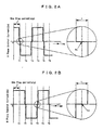
- Fig. 1 shows an outline of an electric circuit of a stepping motor 1.
- the stepping motor 1 is a two phase bipolar stepping motor driven by two-phase (phase A and phase B) excitation.
- the stepping motor 1 includes: a rotor 3 having a permanent magnet with a multipole magnetization arranged such that two kinds of magnetic poles (N, S) 2 are alternately arrayed in the circumferential direction; at least two stator yokes disposed around the rotor 3 so as to form a multiphase magnetic field with at least two phase;, and coils 4 to excite the stator yokes.
- pulsed control signals (1a, 1b) are applied to the coils 4 by a driving circuit 5, the rotor 3 is caused to rotate according to a predetermined step unit, wherein the rotation angle and the rotation speed of the rotor 3 can be highly precisely controlled by the number and cycle of pulse signals.
- the stepping motor while advantageous in that thanks to its structure the rotor is free from mechanical contact with the stator thus enabling a long life and in that a large static torque can be produced at the time of excitation, has the problem that the rotor fails to normally rotate when the pulse signal has a short cycle or when the load is large, thus causing a so-called synchronization loss.
- the stepping motor is frequently used for precisely controlling the rotation angle and speed, and therefore, when the stepping motor loses synchronization, it is necessary to detect the malfunction state immediately and then perform an error handling procedure, such as halt of the rotation or restoration to the normal rotation.
- the stepping motor is often equipped with a circuit or a system for detecting a state of synchronization loss and then performing an error handling procedure.
- EP1460757 discloses a method of precisely detecting a state of synchronization loss in such a manner that a control signal is halted in each step unit for such a short period of time as not to affect the motor rotation wherein a back EMF voltage induced at a coil is measured during the period of time.
- Figs. 2A and 2B outline the technique of detecting a state of synchronization loss disclosed in European Patent Application Laid-Open No. EP1460757 , wherein control signal waveforms (control current waveforms) of a two-phase stepping motor are shown. It is arranged at each of Phases A and B that each control signal is halted at a predetermined timing in each step period (stp) for such a minute period of time (halt time) (t) as not to affect the motor rotation.
- the halt time t is provided before and after each of inversion timings (T1 to T6) at which current polarity is changed, and a back EMF voltage is measured during the halt time (t).
- the above described methods of detecting a state of synchronization loss may employ an external circuit provided outside, may be incorporated into an IC as an algorithm of a program, or may be installed as a software of a computer, wherein back EMF voltage signals from the coil or data corresponding to the signal are inputted to the electric circuit, the IC or the computer, and if the state of synchronization loss is detected, then a detection signal for indicating synchronization loss is outputted. After the detection signal is outputted, an appropriate error handling procedure is performed, for example, a driving circuit to generate a control signal is to be feedback-controlled according to the detection signal.
- the present inventors, et al made a field-investigation into the conventional methods of detecting synchronization loss and found out that it happens with a high probability that the circuit functions improperly such that synchronization loss is judged to occur even prior to actually occurring or fails to be detected in spite of actually occurring.
- et al conducted a simulation for detecting synchronization loss according to the method described in European Patent Application Laid-Open No. EP1460757 .
- a gear box was combined with the stepping motor 1 shown in Fig. 1 thereby providing an actuator, and the back EMF voltages (VA, VB) were measured at the time of increasingly applying a torque load to the output gear of the actuator as well as at the time of locking the output gear, that is, at the state of synchronization loss, and the result gained when the algorithm based on the method described in European Patent Application Laid-Open No. EP1460757 was applied was simulated.
- the present inventors, et al assumed that in order to detect synchronization loss of a stepping motor with an enhanced precision, it is necessary to closely analyze a back EMF voltage and its fluctuation mode at the time of synchronization loss in addition to employing an optical method of measuring a back EMF voltage, and continued studying the back EMF voltage at the time of synchronization loss.
- the value of back EMF voltage or the fluctuation pattern thereof at the time of synchronization loss are not uniform but diversified.
- the present invention has been made in light of the problems described above and also made based on the above findings, and it is an object of the present invention to provide a method of detecting a state of synchronization loss, which is performed based on a back EMF voltage induced at a coil, and in which the state of synchronization loss can be precisely detected while the maximum motor torque can be fully utilized.
- a method of detecting a state of synchronization loss in a stepping motor in which a means for applying either control current or control voltage to a coil of each phase to thereby drive an N-phase stepping motor and a means for individually measuring a back EMF voltage induced at the coil of each phase are employed, wherein application of either the control current or the control voltage at the coil of each phase is halted by turns phase by phase for such a short period of time as not to affect the rotation of a rotor of the stepping motor at a predetermined timing within one step period of the rotor, the back EMF voltage at the coil is measured during the short period of time, and the stepping motor is judged to lose synchronization when the measurement result of the back EMF voltage at the coil of at least one phase satisfies a predetermined detection criterion.
- the detection criterion may be defined by any one of (A) to (D) which follow below:
- the detection criterion may be further defined such that any one of the above described (A) to (C) is combined with either (E), (E) and (F), or (E) to (G):
- the state of synchronization loss can be further precisely detected while the maximum motor torque can be fully utilized.
- Fig. 1 is a circuit diagram of a two-phase stepping motor
- Figs. 2A and 2B are schematic views of a method of measuring a back EMF voltage in a method of detecting a state of synchronization loss according to the present invention
- Figs. 3A to 3C are graphs of fluctuation patterns of back EMF voltages at respective phases obtained when the stepping motor rotates normally
- Figs. 4A to 4D are graphs of fluctuation patterns of back EMF voltages at the respective phases obtained when the stepping motor loses synchronization
- Figs. 5A to 5E are schematic graphs of detection criteria for the state of synchronization loss.
- the present invention may be embodied, for example, by means of an IC provided with a program to control a stepping motor according to an algorithm according to the present invention, to measure a back EMF voltage at a coil of each phase, and also to judge the state of synchronization loss based on the measurement result, and by means of a computer having the above described program installed therein, wherein the IC and the computer are adapted to measure the back EMF voltage by running the program, and if the measurement result indicates the state of synchronization loss, then an appropriate indication is outputted exactly when the indication signal is detected.
- a signal halt time period is provided at each step period (stp) so as to appear alternately at phase A and phase B as shown in Figs. 2A and 2B , and the back EMF voltage at the signal halt time period is measured phase by phase.
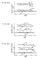
- the fluctuation of a back EMF voltage induced at a coil of each phase of a two-phase stepping motor was measured when a rotor was rotating normally.
- an actuator was constituted by a stepping motor and a gear box as described above, and the back EMF voltage was measured at each of phase A and phase, B when the maximum load to allow a motor rotation was applied to the output gear of the actuator (under load) and also when no load was applied to the output gear of the actuator (under no load).
- the measurement results are shown in graphs of Figs. 3A to 3C .
- the back EMF voltage value marked by Va is the minimum value which is obtained when the rotor was rotating and which is a threshold value as a benchmark for detecting synchronization loss.
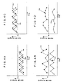
- Fig. 4A shows that both back EMF voltages (12a, 12b) at Phase A and Phase B rise and fall alternately at each measuring point wherein both thereof stay at or below the threshold value Va
- Fig. 4B shows that both back EMF voltages (12a, 12b) at Phase A and Phase B rise and fall alternately at each measuring point wherein one (12a) of both thereof stays at or below the threshold value Va
- Fig. 4A shows that both back EMF voltages (12a, 12b) at Phase A and Phase B rise and fall alternately at each measuring point wherein one (12a) of both thereof stays at or below the threshold value Va
- Fig. 4B shows that both back EMF voltages (12a, 12b) at Phase A and Phase B rise and fall alternately at each measuring point wherein one (12a) of both thereof stays at or below the threshold value Va
- Fig. 4A shows that both back EMF voltages (12a, 12b) at Phase A and Phase B rise and fall alternately at each measuring point wherein one (12a) of both thereof stays at or below
- FIG. 4C shows that back EMF voltages (12a, 12b) at Phase A and Phase B rise and fall alternately at each measuring point wherein both thereof stay at or above the threshold value Va
- Fig. 4D shows that both back EMF voltages (12a, 12b) at Phase A and Phase B rise and fall irregularly at each measuring point wherein one (12a) of both thereof stays at or below the threshold value Va.
- the result here characteristically shows that the fluctuation value of the back EMF voltage is larger when the motor loses synchronization than when the motor rotates normally.
- Criteria (1) to (5) described below refer to examples of detecting a state of synchronization loss and will be explained with reference to Figs. 5A to 5E , respectively.
- Criteria (1) and (2) are defined such that the back EMF voltage measures at or below the threshold value Va for at least two times, but the present invention is not limited to such a definition and the state of synchronization loss may be judged to occur when the back EMF voltage once measures at or below the threshold value Va. Also, the present invention is not limited in the combination of a plurality of detection criteria to the definitions of Criteria (6) and (7). By appropriately combining the detection criteria, it can be expected that the state of synchronization is detected with a probability of close to 100%. Needless to say, the state of synchronization loss may be judged to occur when any one of all the criteria is satisfied. If the arrangement is made such that the state of synchronization is judged to occur when any one of a plurality of criteria is satisfied, it is advantageous in saving the time between the actual occurrence of synchronization loss and the detection of synchronization loss.
- the state of synchronization loss can be judged to occur when the back EMF voltage at any one phase satisfies the criteria, and therefore the method can be applied to not only a two-phase stepping motor but also an N-phase stepping motor.
- the present invention is not limited in the timing of measurement of the back EMF voltage to the timings (T1 to T6 in Figs. 2A and 2B ) at which the polarity of control current flowing at each coil is reversed, and the back EMF voltage can be measured at any arbitrary timing within one step period (stp) on the assumption that the halt time (t) is such a short period of time as not to affect the motor rotation.
Abstract

Description
- The present invention relates to a method of detecting a state of synchronization loss in a stepping motor. Specifically, the present invention relates to a method of detecting a state of synchronization loss, in which the state of synchronization loss in an N-phase stepping motor is detected by using a means for applying either control current or voltage to a coil of each phase to thereby drive the N-phase stepping motor and a means for individually measuring a back EMF voltage induced at the coil of each phase.
-
Fig. 1 shows an outline of an electric circuit of a stepping motor 1. In this example, the stepping motor 1 is a two phase bipolar stepping motor driven by two-phase (phase A and phase B) excitation. The stepping motor 1, as well known, includes: arotor 3 having a permanent magnet with a multipole magnetization arranged such that two kinds of magnetic poles (N, S) 2 are alternately arrayed in the circumferential direction; at least two stator yokes disposed around therotor 3 so as to form a multiphase magnetic field with at least two phase;, andcoils 4 to excite the stator yokes. When pulsed control signals (1a, 1b) are applied to thecoils 4 by adriving circuit 5, therotor 3 is caused to rotate according to a predetermined step unit, wherein the rotation angle and the rotation speed of therotor 3 can be highly precisely controlled by the number and cycle of pulse signals. - The stepping motor, while advantageous in that thanks to its structure the rotor is free from mechanical contact with the stator thus enabling a long life and in that a large static torque can be produced at the time of excitation, has the problem that the rotor fails to normally rotate when the pulse signal has a short cycle or when the load is large, thus causing a so-called synchronization loss. The stepping motor is frequently used for precisely controlling the rotation angle and speed, and therefore, when the stepping motor loses synchronization, it is necessary to detect the malfunction state immediately and then perform an error handling procedure, such as halt of the rotation or restoration to the normal rotation. To this end, the stepping motor is often equipped with a circuit or a system for detecting a state of synchronization loss and then performing an error handling procedure.
- Conventional methods of detecting a state of synchronization loss are described in, for example, Japanese Patent Application Laid-Open No.
2000-166297 EP1460757 , in which back EMF voltages (refer to VA, VB inFig. 1 ) induced at coils by the rotational behavior of a rotor are measured thereby detecting a state of synchronization loss. Specifically, Japanese Patent Application Laid-Open No.2000-166297 EP1460757 discloses a method of precisely detecting a state of synchronization loss in such a manner that a control signal is halted in each step unit for such a short period of time as not to affect the motor rotation wherein a back EMF voltage induced at a coil is measured during the period of time. -
Figs. 2A and 2B outline the technique of detecting a state of synchronization loss disclosed in European Patent Application Laid-Open No.EP1460757 , wherein control signal waveforms (control current waveforms) of a two-phase stepping motor are shown. It is arranged at each of Phases A and B that each control signal is halted at a predetermined timing in each step period (stp) for such a minute period of time (halt time) (t) as not to affect the motor rotation. In this example, the halt time t is provided before and after each of inversion timings (T1 to T6) at which current polarity is changed, and a back EMF voltage is measured during the halt time (t). - The above described methods of detecting a state of synchronization loss may employ an external circuit provided outside, may be incorporated into an IC as an algorithm of a program, or may be installed as a software of a computer, wherein back EMF voltage signals from the coil or data corresponding to the signal are inputted to the electric circuit, the IC or the computer, and if the state of synchronization loss is detected, then a detection signal for indicating synchronization loss is outputted. After the detection signal is outputted, an appropriate error handling procedure is performed, for example, a driving circuit to generate a control signal is to be feedback-controlled according to the detection signal.
- The present inventors, et al made a field-investigation into the conventional methods of detecting synchronization loss and found out that it happens with a high probability that the circuit functions improperly such that synchronization loss is judged to occur even prior to actually occurring or fails to be detected in spite of actually occurring. This happens because the motor, when losing synchronization, is caused to rotate and halt repeatedly with short quick steps instead of stopping its rotation, wherein the state of repetition of rotation and halt is significantly fluctuated depending on the motor rotation speed, the load, and the positional relation between the stator yoke and the magnetic domain of the multipole-magnetized rotor, Accordingly, the back EMF voltage fluctuation to indicate the state of synchronization loss is diversified, and therefore it is not possible to determine the occurrence of synchronization loss based simply on the assumption that the back EMF voltage fluctuates in a predetermined manner at a predetermined coil of at least one phase as described in Japanese Patent Application Laid-Open No.
2000-126297 EP1460757 . - Further, the present inventors, et al conducted a simulation for detecting synchronization loss according to the method described in European Patent Application Laid-Open No.
EP1460757 . Specifically, a gear box was combined with the stepping motor 1 shown inFig. 1 thereby providing an actuator, and the back EMF voltages (VA, VB) were measured at the time of increasingly applying a torque load to the output gear of the actuator as well as at the time of locking the output gear, that is, at the state of synchronization loss, and the result gained when the algorithm based on the method described in European Patent Application Laid-Open No.EP1460757 was applied was simulated. In this connection, when the output gear was locked, the positional relation between the stator yoke and themagnetic poles 2 was shifted at each test thereby reproducing various states of synchronization loss. The simulation result shows that the stepping motor 1 is judged to lose synchronization when rotating with a torque corresponding to about 70% of the torque value at which the stepping motor 1 actually gets out of synchronization, which means that the maximum torque of the stepping motor 1 cannot be fully utilized. Also, it was found out that the state of synchronization loss is detected with a probability of 85%. - The present inventors, et al assumed that in order to detect synchronization loss of a stepping motor with an enhanced precision, it is necessary to closely analyze a back EMF voltage and its fluctuation mode at the time of synchronization loss in addition to employing an optical method of measuring a back EMF voltage, and continued studying the back EMF voltage at the time of synchronization loss. As the result of the study, it was found out that it is important to judge the motor loses synchronization at the very time of detecting an indication of synchronization loss at any one of phases the back EMF voltage when the back EMF is analyzed individually at each phase of an N-phase stepping motor. Also, it was found out that the value of back EMF voltage or the fluctuation pattern thereof at the time of synchronization loss are not uniform but diversified.
- The present invention has been made in light of the problems described above and also made based on the above findings, and it is an object of the present invention to provide a method of detecting a state of synchronization loss, which is performed based on a back EMF voltage induced at a coil, and in which the state of synchronization loss can be precisely detected while the maximum motor torque can be fully utilized.
- In order to achieve the object described above, according to an aspect of the present invention, there is provided a method of detecting a state of synchronization loss in a stepping motor, in which a means for applying either control current or control voltage to a coil of each phase to thereby drive an N-phase stepping motor and a means for individually measuring a back EMF voltage induced at the coil of each phase are employed, wherein application of either the control current or the control voltage at the coil of each phase is halted by turns phase by phase for such a short period of time as not to affect the rotation of a rotor of the stepping motor at a predetermined timing within one step period of the rotor, the back EMF voltage at the coil is measured during the short period of time, and the stepping motor is judged to lose synchronization when the measurement result of the back EMF voltage at the coil of at least one phase satisfies a predetermined detection criterion.
- In the aspect of the present invention, the detection criterion may be defined by any one of (A) to (D) which follow below:
- (A) The back EMF voltage measures at or below the predetermined value Va.
- (B) The back EMF voltage measures at or below the predetermined value Va for at least a predetermined consecutive number (a) of times.
- (C) The back EMF voltage measures at or below the predetermine value Va for at least a predetermined number (c) of times through a predetermined number (b) of measuring points.
- (D) The absolute value of the back EMF fluctuation between adjacent measuring points measures at or above the predetermined value Vb.
- In the present invention, the detection criterion may be further defined such that any one of the above described (A) to (C) is combined with either (E), (E) and (F), or (E) to (G):
- (E) The absolute value of the back EMF fluctuation between adjacent measuring points measures at or above the predetermined value Vb.
- (F) The absolute value of the back EMF fluctuation between adjacent measuring points measures at or above the predetermined value Vb for at least a predetermined number (d) of times.
- (G) The difference between adjacent absolute values of the back EMF voltage fluctuation between adjacent measuring points measures at or below the predetermined value Vc.
- Thus, according to the present invention, the state of synchronization loss can be further precisely detected while the maximum motor torque can be fully utilized.
-
Fig. 1 is a circuit diagram of a two-phase stepping motor;
Figs. 2A and 2B are schematic views of a method of measuring a back EMF voltage in a method of detecting a state of synchronization loss according to the present invention;
Figs. 3A to 3C are graphs of fluctuation patterns of back EMF voltages at respective phases obtained when the stepping motor rotates normally;
Figs. 4A to 4D are graphs of fluctuation patterns of back EMF voltages at the respective phases obtained when the stepping motor loses synchronization; and
Figs. 5A to 5E are schematic graphs of detection criteria for the state of synchronization loss. - Exemplary embodiments of the present invention will hereinafter be described with reference to the accompanying drawings.
- The present invention may be embodied, for example, by means of an IC provided with a program to control a stepping motor according to an algorithm according to the present invention, to measure a back EMF voltage at a coil of each phase, and also to judge the state of synchronization loss based on the measurement result, and by means of a computer having the above described program installed therein, wherein the IC and the computer are adapted to measure the back EMF voltage by running the program, and if the measurement result indicates the state of synchronization loss, then an appropriate indication is outputted exactly when the indication signal is detected. Also, in the present invention, a signal halt time period is provided at each step period (stp) so as to appear alternately at phase A and phase B as shown in
Figs. 2A and 2B , and the back EMF voltage at the signal halt time period is measured phase by phase. - First, the fluctuation of a back EMF voltage induced at a coil of each phase of a two-phase stepping motor was measured when a rotor was rotating normally. For performing the measurement, an actuator was constituted by a stepping motor and a gear box as described above, and the back EMF voltage was measured at each of phase A and phase, B when the maximum load to allow a motor rotation was applied to the output gear of the actuator (under load) and also when no load was applied to the output gear of the actuator (under no load). The measurement results are shown in graphs of
Figs. 3A to 3C . In this connection, the back EMF voltage value marked by Va is the minimum value which is obtained when the rotor was rotating and which is a threshold value as a benchmark for detecting synchronization loss. - Referring to
Figs. 3A to 3C , no regularity is found in the fluctuation pattern of the back EMF voltage at Phase A (10a, 11a), Phase B (10b, 11b), under load (10a, 10b) and under no load (11a, 11b) obtained when the motor is running, for example, such that the threshold value Va is measured "at Phase B under load (10b)" inFigs. 3A and 3B while measured "at Phase A under no load (11a)" inFig. 3C . Also, with regard to the rise and fall of the back EMF voltage at adjacent measuring points, a regularity is seen, for example, "at Phase B under load (10b)" shown inFig. 3B and "at Phase under no load (11a)" shown inFig. 3C , where the back EMF voltage rises and falls in an alternate manner, while such a regularity is not seen in other back EMF voltage characteristics. - Next, the back EMF voltage was measured when the output gear of the actuator was locked thereby driving the motor out of synchronization. The measurement result shows that there are various types of fluctuation patterns in the back EMF voltages at Phase A and Phase B when the motor loses synchronization. Some of the fluctuation pattern types are shown in graphs of
Figs. 4A, to 4D. Fig. 4A , shows that both back EMF voltages (12a, 12b) at Phase A and Phase B rise and fall alternately at each measuring point wherein both thereof stay at or below the threshold value Va,Fig. 4B shows that both back EMF voltages (12a, 12b) at Phase A and Phase B rise and fall alternately at each measuring point wherein one (12a) of both thereof stays at or below the threshold value Va,Fig. 4C shows that back EMF voltages (12a, 12b) at Phase A and Phase B rise and fall alternately at each measuring point wherein both thereof stay at or above the threshold value Va, andFig. 4D shows that both back EMF voltages (12a, 12b) at Phase A and Phase B rise and fall irregularly at each measuring point wherein one (12a) of both thereof stays at or below the threshold value Va. The result here characteristically shows that the fluctuation value of the back EMF voltage is larger when the motor loses synchronization than when the motor rotates normally. - It can be said that it is possible that the motor loses synchronization if the fluctuation patterns shown in
Figs. 4A to 4B are obtained by the measurement, but in order to precisely detect synchronization loss from the fluctuation patterns, it is necessary to define more concrete criteria for determining the state of synchronization loss which are potentially present in the fluctuation patterns. So, the present inventors, et al analyzed the various fluctuation patterns in greater detail and succeeded in establishing some criteria for detecting a state of synchronization loss. - Criteria (1) to (5) described below refer to examples of detecting a state of synchronization loss and will be explained with reference to
Figs. 5A to 5E , respectively. - (1) A back EMF voltage V at any one phase measures at or below the threshold value Va for at least a predetermined consecutive number (a: reference numeral 13) of times:
Fig. 5A , - (2) A back EMF voltage V at any one phase measures at or below the threshold value Va for at least a predetermined number (c: reference numeral 15) of times through a predetermined number (b: reference numeral 14) of measuring points:
Fig. 5B , - (3) A back EMF voltage difference (absolute value of a back EMF voltage fluctuation) ΔV found between adjacent measuring points at any one phase measures at or above a predetermined threshold value Vb for at least a predetermine consecutive number (d: reference numeral 16) of measuring points:
Fig. 5C , - (4) In addition to Criterion (3), a back EMF voltage obtained at each of (d times of) consecutive measuring points in Criterion (3) rises and falls in an alternate manner:
Fig. 5D , and - (5) In addition to Criteria (3) and (4), a difference (absolute value of the fluctuation between respective absolute values ΔV of adjacent back EMF voltage fluctuations) ΔV found between adjacent rise and fall values in Criterion (4) measures at or below a predetermined threshold Vc:
Fig. 5E . - Field tests (first to fifth embodiments) were conducted to see if the state of synchronization loss of the motor in the actuator can be appropriately detected according respectively to Criteria (1) to (5) described above. In addition to the above tests which were performed by applying Criteria (1) to (5) singularly and independently, a test (sixth embodiment) was conducted by applying Criterion (6) which is defined such that either Criterion (2) or (4) is satisfied, and still another test (seventh embodiment) was conducted by applying Criterion (7) which is defined such that either Criterion (2) or (5) is satisfied. In the tests conducted as described above, the numbers (a) to (d) of times or measuring points are set as follows: a=3, b=8, c=3, and d=4.
- The test results are shown in Table 1 below.
[Table 1] Test Detection criterion Method 1 Method 2*T (%) **p (%) (1) Back EMF voltage at any one phase measures at or below the threshold value Va for three or more consecutive times 100 90 (2) Back EMF voltage at any one phase measures at or below the threshold value Va for three or more times through eight consecutive measuring points 100 93 (3) Absolute value ΔV of back EMF voltage fluctuation at any one phase measures at or above the predetermined threshold value Vb for four or more consecutive times 100 50 (4) In addition to (3), back EMF voltage rises and falls alternately at four or more consecutive measuring points in (3) 100 70 (5) In addition to (3) and (4), absolute value ΔV of fluctuation between adjacent absolute values ΔV of the back EMF voltage fluctuation in (4) measures at or below the predetermined threshold Vc (for three consecutive times) 100 75 (6) Either criterion (2) or (4) is satisfied 100 98 (7) Either criterion (2) or (5) is satisfied 100 100 Criteria (1) to (7) correspond to first to seventh Embodiments, respectively
*T: Torque at time of detection of synchronization loss
**P: Probability of detection - In each test, a load was increasingly applied to the output gear of the actuator, a torque was measured when the motor practically lost synchronization, and the ratio of a torque value reading at the time of detection of the state of synchronization loss relative to the value of the torque measured as described above was calculated, which is shown in Method 1, where the ratio is 100% for all tests, which means that the synchronization loss was detected exactly at the time of actually occurring when the load attributable to causing the synchronization loss was applied. Consequently, when the method of detecting the state of synchronization loss based on the criterion of each embodiment described above is used, the stepping motor of the actuator is allowed to perform up to its maximum torque capacity.
- In each test, when the output gear of the actuator was locked thereby causing the motor to lose synchronization, the probability of actually detecting synchronization loss was examined with respect to the detection criterion according to each embodiment, wherein when the output gear was locked, the positional relation between a stator yoke and magnetic poles was shifted for each test thereby presenting various states of synchronization loss, and the examination result is shown in
Method 2. The first and second embodiments enabled the state of synchronization loss to be duly detected with a probability of 90% or more, and the third, fourth and fifth embodiments enabled the state of synchronization loss to be detected with a probability of 50%, 70% and 75%, respectively. On the other hand, at the sixth embodiment in which synchronization loss is detected based on Criterion (6) defined such that synchronization loss is judged to occur when either Criterion (2) or (4) is satisfied, the state of synchronization loss could be detected with a probability of 98%, and also at the seventh embodiment in which synchronization loss is detected based on Criterion (7) defined such that synchronization loss is judged to occur when either Criterion (2) or (5) is satisfied, the state of synchronization loss could be detected with a probability of 100%. This means that Criteria (1) and (2) can be well complemented when combined with another criterion. - Criteria (1) and (2) are defined such that the back EMF voltage measures at or below the threshold value Va for at least two times, but the present invention is not limited to such a definition and the state of synchronization loss may be judged to occur when the back EMF voltage once measures at or below the threshold value Va. Also, the present invention is not limited in the combination of a plurality of detection criteria to the definitions of Criteria (6) and (7). By appropriately combining the detection criteria, it can be expected that the state of synchronization is detected with a probability of close to 100%. Needless to say, the state of synchronization loss may be judged to occur when any one of all the criteria is satisfied. If the arrangement is made such that the state of synchronization is judged to occur when any one of a plurality of criteria is satisfied, it is advantageous in saving the time between the actual occurrence of synchronization loss and the detection of synchronization loss.
- In the present invention, the state of synchronization loss can be judged to occur when the back EMF voltage at any one phase satisfies the criteria, and therefore the method can be applied to not only a two-phase stepping motor but also an N-phase stepping motor. Also, the present invention is not limited in the timing of measurement of the back EMF voltage to the timings (T1 to T6 in
Figs. 2A and 2B ) at which the polarity of control current flowing at each coil is reversed, and the back EMF voltage can be measured at any arbitrary timing within one step period (stp) on the assumption that the halt time (t) is such a short period of time as not to affect the motor rotation.
Claims (8)
- A method of detecting a state of synchronization loss in a stepping motor, in which a means for applying one of control current and control voltage to a coil (4) of each phase to thereby drive an N-phase stepping motor (1) and a means for individually measuring a back EMF voltage (V) induced at the coil (4) of each phase are employed,
characterized in that application of the one of the control current and the control voltage at the coil (4) of each phase is halted by turns phase by phase for such a short period of time (t) as not to affect rotation of a rotor (3) of the stepping motor (1) at a predetermined timing within one step period (stp) of the rotor (3), and the back EMF voltage (V) at the coil (4) is measured during the short period of time (t), wherein the stepping, motor (1) is judged to lose synchronization when a measurement result of the back EMF voltage (V) at the coil (4) of at least one phase satisfies a predetermined detection criterion. - A method of detecting a state of synchronization loss in a stepping motor according to Claim 1, wherein the detection criterion is defined such that the back EMF voltage (V) measures at or below a first predetermined value (Va).
- A method of detecting a state of synchronization loss in a stepping motor according to Claim 1, wherein the detection criterion is defined such that the back EMF voltage (V) measures at or below a first predetermined value (Va) for at least a predetermined consecutive number (a) of times.
- A method of detecting a state of synchronization loss in a stepping motor according to Claim 1, wherein the detection criterion is defined such that the back EMF voltage (V) measures at or below a first predetermined value (Va) for at least a predetermined number (c) of times through a predetermined number (b) of measuring points.
- A method of detecting a state of synchronization loss in a stepping motor according to Claim 1, wherein the detection criterion is defined such that an absolute value (ΔV) of a back EMF voltage fluctuation between adjacent measuring points measures at or above a second predetermined value (Vb).
- A method of detecting a state of synchronization loss in a stepping motor according to any one of Claims 2 to 4, wherein the detection criterion is defined to further include that an absolute value (ΔV) of a back EMF voltage fluctuation between adjacent measuring points measures at or above a second predetermined value (Vb).
- A method of detecting a state of synchronization loss in a stepping motor according to Claim 6, wherein the detection criterion is defined to further include that the absolute value (ΔV) of the back EMF voltage fluctuation between adjacent measuring points measures at or above the second predetermined value (Vb) for at least a predetermined consecutive number (d) of times, and at the same time that the back EMF voltage (V) obtained at the adjacent measuring points rises and falls in an alternate manner.
- A method of detecting a state of synchronization loss in a stepping motor according to Claim 7, wherein the detection criterion is defined to further include that a difference (ΔΔV) between adjacent absolute values (ΔV) of the back EMF voltage fluctuation between adjacent measuring points measures at or below a third predetermined value (Vc).
Applications Claiming Priority (1)
| Application Number | Priority Date | Filing Date | Title |
|---|---|---|---|
| JP2008103830A JP5331370B2 (en) | 2008-04-11 | 2008-04-11 | Stepping motor out-of-step detection method |
Publications (3)
| Publication Number | Publication Date |
|---|---|
| EP2110942A2 true EP2110942A2 (en) | 2009-10-21 |
| EP2110942A3 EP2110942A3 (en) | 2015-08-19 |
| EP2110942B1 EP2110942B1 (en) | 2017-11-08 |
Family
ID=41050525
Family Applications (1)
| Application Number | Title | Priority Date | Filing Date |
|---|---|---|---|
| EP09005045.1A Active EP2110942B1 (en) | 2008-04-11 | 2009-04-06 | Method of detecting state of synchronization loss in stepping motor |
Country Status (3)
| Country | Link |
|---|---|
| US (1) | US8174223B2 (en) |
| EP (1) | EP2110942B1 (en) |
| JP (1) | JP5331370B2 (en) |
Cited By (1)
| Publication number | Priority date | Publication date | Assignee | Title |
|---|---|---|---|---|
| CN110022099A (en) * | 2019-04-29 | 2019-07-16 | 青岛海信日立空调系统有限公司 | A kind of detection method and device of permanent magnet synchronous motor step-out |
Families Citing this family (16)
| Publication number | Priority date | Publication date | Assignee | Title |
|---|---|---|---|---|
| DE102010000286B4 (en) * | 2009-02-05 | 2019-05-23 | Denso Corporation | Indicator for a vehicle |
| JP5591508B2 (en) * | 2009-09-18 | 2014-09-17 | セミコンダクター・コンポーネンツ・インダストリーズ・リミテッド・ライアビリティ・カンパニー | Driver circuit |
| JP5591507B2 (en) * | 2009-09-18 | 2014-09-17 | セミコンダクター・コンポーネンツ・インダストリーズ・リミテッド・ライアビリティ・カンパニー | Driver circuit |
| JP5697320B2 (en) * | 2009-09-18 | 2015-04-08 | セミコンダクター・コンポーネンツ・インダストリーズ・リミテッド・ライアビリティ・カンパニー | Driver circuit |
| US8242732B2 (en) * | 2009-12-18 | 2012-08-14 | Xylon d.o.o. | Apparatus, system and method for stepper motor stall detection |
| JP5786283B2 (en) * | 2010-06-04 | 2015-09-30 | 株式会社リコー | Motor control apparatus, image forming apparatus, and motor control method |
| JP2012016221A (en) | 2010-07-02 | 2012-01-19 | Minebea Co Ltd | Motor control device and step-out state detection method |
| JP5936883B2 (en) | 2012-03-02 | 2016-06-22 | ミネベア株式会社 | Motor controller and stepping motor step-out state determination method |
| JP2014128070A (en) * | 2012-12-25 | 2014-07-07 | Minebea Co Ltd | Motor controller and method for controlling stepping motor |
| JP2015142441A (en) | 2014-01-29 | 2015-08-03 | ミネベア株式会社 | Motor control device and step-out state detection method |
| JP6537347B2 (en) * | 2015-05-14 | 2019-07-03 | 大和製衡株式会社 | Combination balance |
| JP2017038492A (en) * | 2015-08-12 | 2017-02-16 | 株式会社メレック | Step-out determination device and step-out determination method for stepping motor |
| JP6548619B2 (en) * | 2016-08-31 | 2019-07-24 | ミネベアミツミ株式会社 | Motor control device and method for detecting out-of-step condition |
| JP6727173B2 (en) | 2017-08-18 | 2020-07-22 | 株式会社東芝 | Rotor position detection system |
| JP7129802B2 (en) * | 2018-03-23 | 2022-09-02 | ミネベアミツミ株式会社 | Motor control device, stepping motor system and motor control method |
| CN110076412B (en) * | 2019-04-16 | 2021-08-06 | 深圳市麦格米特焊接技术有限公司 | Double-motor cooperative control method and device, motor controller and wire feeding system |
Citations (3)
| Publication number | Priority date | Publication date | Assignee | Title |
|---|---|---|---|---|
| JP2000126297A (en) | 1998-10-27 | 2000-05-09 | Siemens Elema Ab | Anesthetizer |
| JP2000166297A (en) | 1998-11-27 | 2000-06-16 | Seiko Epson Corp | Drive device and drive mechanism of stepping motor |
| EP1460757A1 (en) | 2003-03-21 | 2004-09-22 | AMI Semiconductor Belgium BVBA | Device and method for detecting rotor speed of a multiple phase motor with bipolar drive |
Family Cites Families (11)
| Publication number | Priority date | Publication date | Assignee | Title |
|---|---|---|---|---|
| US4283783A (en) * | 1978-11-28 | 1981-08-11 | Citizen Watch Company Limited | Drive control system for stepping motor |
| JPS60257793A (en) * | 1984-06-01 | 1985-12-19 | Matsushita Electric Ind Co Ltd | Rotation detector of stepping motor |
| US4743848A (en) * | 1986-07-17 | 1988-05-10 | International Business Machines Corporation | Method of testing a stepping motor |
| JPH0750998B2 (en) * | 1989-01-09 | 1995-05-31 | アスモ株式会社 | Step motor abnormality detection device |
| JPH07131997A (en) * | 1993-11-05 | 1995-05-19 | Yamaha Motor Co Ltd | Rotational condition detecting device for step motor |
| JPH0898597A (en) * | 1994-09-16 | 1996-04-12 | Nissan Motor Co Ltd | Controller of stepping motor |
| DE19860110A1 (en) * | 1998-12-23 | 2000-07-06 | Mannesmann Vdo Ag | Method for monitoring the speed of a synchronous motor and device for monitoring the speed of such a motor |
| US6586898B2 (en) * | 2001-05-01 | 2003-07-01 | Magnon Engineering, Inc. | Systems and methods of electric motor control |
| JP2002365379A (en) * | 2001-06-11 | 2002-12-18 | Seiko Instruments Inc | Analog electronic clock |
| JP5559504B2 (en) * | 2009-09-30 | 2014-07-23 | セミコンダクター・コンポーネンツ・インダストリーズ・リミテッド・ライアビリティ・カンパニー | Motor drive control circuit |
| US8242732B2 (en) * | 2009-12-18 | 2012-08-14 | Xylon d.o.o. | Apparatus, system and method for stepper motor stall detection |
-
2008
- 2008-04-11 JP JP2008103830A patent/JP5331370B2/en active Active
-
2009
- 2009-03-25 US US12/382,853 patent/US8174223B2/en active Active
- 2009-04-06 EP EP09005045.1A patent/EP2110942B1/en active Active
Patent Citations (3)
| Publication number | Priority date | Publication date | Assignee | Title |
|---|---|---|---|---|
| JP2000126297A (en) | 1998-10-27 | 2000-05-09 | Siemens Elema Ab | Anesthetizer |
| JP2000166297A (en) | 1998-11-27 | 2000-06-16 | Seiko Epson Corp | Drive device and drive mechanism of stepping motor |
| EP1460757A1 (en) | 2003-03-21 | 2004-09-22 | AMI Semiconductor Belgium BVBA | Device and method for detecting rotor speed of a multiple phase motor with bipolar drive |
Cited By (1)
| Publication number | Priority date | Publication date | Assignee | Title |
|---|---|---|---|---|
| CN110022099A (en) * | 2019-04-29 | 2019-07-16 | 青岛海信日立空调系统有限公司 | A kind of detection method and device of permanent magnet synchronous motor step-out |
Also Published As
| Publication number | Publication date |
|---|---|
| US20090256515A1 (en) | 2009-10-15 |
| JP5331370B2 (en) | 2013-10-30 |
| US8174223B2 (en) | 2012-05-08 |
| EP2110942B1 (en) | 2017-11-08 |
| EP2110942A3 (en) | 2015-08-19 |
| JP2009261045A (en) | 2009-11-05 |
Similar Documents
| Publication | Publication Date | Title |
|---|---|---|
| EP2110942B1 (en) | Method of detecting state of synchronization loss in stepping motor | |
| EP0462729B1 (en) | Method and apparatus for detecting the rotor position of a brushless DC motor | |
| US8058894B2 (en) | Method for detecting a fault condition | |
| US8610452B2 (en) | Apparatus and method for diagnosing permanent magnet demagnetization of permanent magnet synchronous motor, and apparatus for driving permanent magnet synchronous motor | |
| US8754640B2 (en) | Magnetic field sensors and related techniques that can provide self-test information in a formatted output signal | |
| US5001405A (en) | Position detection for a brushless DC motor | |
| US8040095B2 (en) | Synchronization of sequential phase switchings in driving stator windings of a multiphase sensorless brushless motor at sub BEMF-detectability speeds | |
| CN104579056B (en) | A kind of method for compensating step motor position error | |
| US8466648B2 (en) | Motor control device and out-of-step detecting method | |
| US7622882B2 (en) | Position detection device for permanent magnetic machines | |
| EP2345148B1 (en) | Method of detecting an operating condition of an electric stepper motor | |
| US11005397B2 (en) | Method of detecting the angular position of an electric motor, corresponding circuit and electric motor | |
| US8896257B2 (en) | Motor control device and out-of-step detecting method of stepping motor | |
| US8907606B2 (en) | Method and device for determining a rotor position of a synchronous machine | |
| EP0394902A1 (en) | Driving circuit for stepping motor | |
| CN110221092A (en) | Revolving speed steering detection method, electrical fault detection method, detection system and motor | |
| US8736298B2 (en) | Method for detecting a step loss condition | |
| KR100327862B1 (en) | Initial position detection and starting algorithm of BLDC motor using inductance variation | |
| Feuersänger et al. | Initial rotor position detection in synchronous machines using low frequency pulses | |
| EP3667894B1 (en) | Method for determining the rotational position of a rotor in a permanent magnet synchronous machine | |
| JP2008278580A (en) | Method and device for inspecting static frictional torque of motor | |
| Lee et al. | Measurement of flux linkage in the hybrid stepping motor drive | |
| SU1467728A1 (en) | Unit for testing and calibrating a stepping motor | |
| CN115001351A (en) | Method for detecting initial position of rotor of permanent magnet synchronous motor | |
| JP2002218795A (en) | Stepping motor origin setting device, stepping motor origin setting method, and optical device having the stepping motor origin setting device |
Legal Events
| Date | Code | Title | Description |
|---|---|---|---|
| PUAI | Public reference made under article 153(3) epc to a published international application that has entered the european phase |
Free format text: ORIGINAL CODE: 0009012 |
|
| AK | Designated contracting states |
Kind code of ref document: A2 Designated state(s): AT BE BG CH CY CZ DE DK EE ES FI FR GB GR HR HU IE IS IT LI LT LU LV MC MK MT NL NO PL PT RO SE SI SK TR |
|
| PUAL | Search report despatched |
Free format text: ORIGINAL CODE: 0009013 |
|
| AK | Designated contracting states |
Kind code of ref document: A3 Designated state(s): AT BE BG CH CY CZ DE DK EE ES FI FR GB GR HR HU IE IS IT LI LT LU LV MC MK MT NL NO PL PT RO SE SI SK TR |
|
| AX | Request for extension of the european patent |
Extension state: AL BA RS |
|
| RIC1 | Information provided on ipc code assigned before grant |
Ipc: H02P 8/38 20060101AFI20150710BHEP Ipc: H02P 8/32 20060101ALI20150710BHEP Ipc: H02P 8/36 20060101ALI20150710BHEP Ipc: H02P 8/34 20060101ALI20150710BHEP |
|
| 17P | Request for examination filed |
Effective date: 20160217 |
|
| RBV | Designated contracting states (corrected) |
Designated state(s): AT BE BG CH CY CZ DE DK EE ES FI FR GB GR HR HU IE IS IT LI LT LU LV MC MK MT NL NO PL PT RO SE SI SK TR |
|
| 17Q | First examination report despatched |
Effective date: 20160419 |
|
| GRAP | Despatch of communication of intention to grant a patent |
Free format text: ORIGINAL CODE: EPIDOSNIGR1 |
|
| STAA | Information on the status of an ep patent application or granted ep patent |
Free format text: STATUS: GRANT OF PATENT IS INTENDED |
|
| INTG | Intention to grant announced |
Effective date: 20170530 |
|
| GRAS | Grant fee paid |
Free format text: ORIGINAL CODE: EPIDOSNIGR3 |
|
| GRAA | (expected) grant |
Free format text: ORIGINAL CODE: 0009210 |
|
| STAA | Information on the status of an ep patent application or granted ep patent |
Free format text: STATUS: THE PATENT HAS BEEN GRANTED |
|
| AK | Designated contracting states |
Kind code of ref document: B1 Designated state(s): AT BE BG CH CY CZ DE DK EE ES FI FR GB GR HR HU IE IS IT LI LT LU LV MC MK MT NL NO PL PT RO SE SI SK TR |
|
| REG | Reference to a national code |
Ref country code: GB Ref legal event code: FG4D |
|
| REG | Reference to a national code |
Ref country code: CH Ref legal event code: EP Ref country code: AT Ref legal event code: REF Ref document number: 945074 Country of ref document: AT Kind code of ref document: T Effective date: 20171115 |
|
| REG | Reference to a national code |
Ref country code: IE Ref legal event code: FG4D |
|
| REG | Reference to a national code |
Ref country code: DE Ref legal event code: R096 Ref document number: 602009049213 Country of ref document: DE |
|
| REG | Reference to a national code |
Ref country code: NL Ref legal event code: MP Effective date: 20171108 |
|
| REG | Reference to a national code |
Ref country code: LT Ref legal event code: MG4D |
|
| REG | Reference to a national code |
Ref country code: AT Ref legal event code: MK05 Ref document number: 945074 Country of ref document: AT Kind code of ref document: T Effective date: 20171108 |
|
| REG | Reference to a national code |
Ref country code: DE Ref legal event code: R082 Ref document number: 602009049213 Country of ref document: DE Representative=s name: UEXKUELL & STOLBERG PARTNERSCHAFT VON PATENT- , DE Ref country code: DE Ref legal event code: R081 Ref document number: 602009049213 Country of ref document: DE Owner name: MINEBEA MITSUMI INC., MIYOTA-MACHI, JP Free format text: FORMER OWNER: MINEBEA CO. LTD., MIYOTA, JP |
|
| PG25 | Lapsed in a contracting state [announced via postgrant information from national office to epo] |
Ref country code: NL Free format text: LAPSE BECAUSE OF FAILURE TO SUBMIT A TRANSLATION OF THE DESCRIPTION OR TO PAY THE FEE WITHIN THE PRESCRIBED TIME-LIMIT Effective date: 20171108 Ref country code: LT Free format text: LAPSE BECAUSE OF FAILURE TO SUBMIT A TRANSLATION OF THE DESCRIPTION OR TO PAY THE FEE WITHIN THE PRESCRIBED TIME-LIMIT Effective date: 20171108 Ref country code: SE Free format text: LAPSE BECAUSE OF FAILURE TO SUBMIT A TRANSLATION OF THE DESCRIPTION OR TO PAY THE FEE WITHIN THE PRESCRIBED TIME-LIMIT Effective date: 20171108 Ref country code: ES Free format text: LAPSE BECAUSE OF FAILURE TO SUBMIT A TRANSLATION OF THE DESCRIPTION OR TO PAY THE FEE WITHIN THE PRESCRIBED TIME-LIMIT Effective date: 20171108 Ref country code: FI Free format text: LAPSE BECAUSE OF FAILURE TO SUBMIT A TRANSLATION OF THE DESCRIPTION OR TO PAY THE FEE WITHIN THE PRESCRIBED TIME-LIMIT Effective date: 20171108 Ref country code: NO Free format text: LAPSE BECAUSE OF FAILURE TO SUBMIT A TRANSLATION OF THE DESCRIPTION OR TO PAY THE FEE WITHIN THE PRESCRIBED TIME-LIMIT Effective date: 20180208 |
|
| PG25 | Lapsed in a contracting state [announced via postgrant information from national office to epo] |
Ref country code: AT Free format text: LAPSE BECAUSE OF FAILURE TO SUBMIT A TRANSLATION OF THE DESCRIPTION OR TO PAY THE FEE WITHIN THE PRESCRIBED TIME-LIMIT Effective date: 20171108 Ref country code: GR Free format text: LAPSE BECAUSE OF FAILURE TO SUBMIT A TRANSLATION OF THE DESCRIPTION OR TO PAY THE FEE WITHIN THE PRESCRIBED TIME-LIMIT Effective date: 20180209 Ref country code: HR Free format text: LAPSE BECAUSE OF FAILURE TO SUBMIT A TRANSLATION OF THE DESCRIPTION OR TO PAY THE FEE WITHIN THE PRESCRIBED TIME-LIMIT Effective date: 20171108 Ref country code: IS Free format text: LAPSE BECAUSE OF FAILURE TO SUBMIT A TRANSLATION OF THE DESCRIPTION OR TO PAY THE FEE WITHIN THE PRESCRIBED TIME-LIMIT Effective date: 20180308 Ref country code: BG Free format text: LAPSE BECAUSE OF FAILURE TO SUBMIT A TRANSLATION OF THE DESCRIPTION OR TO PAY THE FEE WITHIN THE PRESCRIBED TIME-LIMIT Effective date: 20180208 Ref country code: LV Free format text: LAPSE BECAUSE OF FAILURE TO SUBMIT A TRANSLATION OF THE DESCRIPTION OR TO PAY THE FEE WITHIN THE PRESCRIBED TIME-LIMIT Effective date: 20171108 |
|
| PG25 | Lapsed in a contracting state [announced via postgrant information from national office to epo] |
Ref country code: CZ Free format text: LAPSE BECAUSE OF FAILURE TO SUBMIT A TRANSLATION OF THE DESCRIPTION OR TO PAY THE FEE WITHIN THE PRESCRIBED TIME-LIMIT Effective date: 20171108 Ref country code: SK Free format text: LAPSE BECAUSE OF FAILURE TO SUBMIT A TRANSLATION OF THE DESCRIPTION OR TO PAY THE FEE WITHIN THE PRESCRIBED TIME-LIMIT Effective date: 20171108 Ref country code: EE Free format text: LAPSE BECAUSE OF FAILURE TO SUBMIT A TRANSLATION OF THE DESCRIPTION OR TO PAY THE FEE WITHIN THE PRESCRIBED TIME-LIMIT Effective date: 20171108 Ref country code: CY Free format text: LAPSE BECAUSE OF FAILURE TO SUBMIT A TRANSLATION OF THE DESCRIPTION OR TO PAY THE FEE WITHIN THE PRESCRIBED TIME-LIMIT Effective date: 20171108 Ref country code: DK Free format text: LAPSE BECAUSE OF FAILURE TO SUBMIT A TRANSLATION OF THE DESCRIPTION OR TO PAY THE FEE WITHIN THE PRESCRIBED TIME-LIMIT Effective date: 20171108 |
|
| REG | Reference to a national code |
Ref country code: DE Ref legal event code: R097 Ref document number: 602009049213 Country of ref document: DE |
|
| PG25 | Lapsed in a contracting state [announced via postgrant information from national office to epo] |
Ref country code: RO Free format text: LAPSE BECAUSE OF FAILURE TO SUBMIT A TRANSLATION OF THE DESCRIPTION OR TO PAY THE FEE WITHIN THE PRESCRIBED TIME-LIMIT Effective date: 20171108 Ref country code: IT Free format text: LAPSE BECAUSE OF FAILURE TO SUBMIT A TRANSLATION OF THE DESCRIPTION OR TO PAY THE FEE WITHIN THE PRESCRIBED TIME-LIMIT Effective date: 20171108 Ref country code: PL Free format text: LAPSE BECAUSE OF FAILURE TO SUBMIT A TRANSLATION OF THE DESCRIPTION OR TO PAY THE FEE WITHIN THE PRESCRIBED TIME-LIMIT Effective date: 20171108 |
|
| PLBE | No opposition filed within time limit |
Free format text: ORIGINAL CODE: 0009261 |
|
| STAA | Information on the status of an ep patent application or granted ep patent |
Free format text: STATUS: NO OPPOSITION FILED WITHIN TIME LIMIT |
|
| 26N | No opposition filed |
Effective date: 20180809 |
|
| PG25 | Lapsed in a contracting state [announced via postgrant information from national office to epo] |
Ref country code: SI Free format text: LAPSE BECAUSE OF FAILURE TO SUBMIT A TRANSLATION OF THE DESCRIPTION OR TO PAY THE FEE WITHIN THE PRESCRIBED TIME-LIMIT Effective date: 20171108 Ref country code: MC Free format text: LAPSE BECAUSE OF FAILURE TO SUBMIT A TRANSLATION OF THE DESCRIPTION OR TO PAY THE FEE WITHIN THE PRESCRIBED TIME-LIMIT Effective date: 20171108 |
|
| REG | Reference to a national code |
Ref country code: CH Ref legal event code: PL |
|
| REG | Reference to a national code |
Ref country code: BE Ref legal event code: MM Effective date: 20180430 |
|
| GBPC | Gb: european patent ceased through non-payment of renewal fee |
Effective date: 20180406 |
|
| REG | Reference to a national code |
Ref country code: IE Ref legal event code: MM4A |
|
| PG25 | Lapsed in a contracting state [announced via postgrant information from national office to epo] |
Ref country code: LU Free format text: LAPSE BECAUSE OF NON-PAYMENT OF DUE FEES Effective date: 20180406 |
|
| PG25 | Lapsed in a contracting state [announced via postgrant information from national office to epo] |
Ref country code: BE Free format text: LAPSE BECAUSE OF NON-PAYMENT OF DUE FEES Effective date: 20180430 Ref country code: CH Free format text: LAPSE BECAUSE OF NON-PAYMENT OF DUE FEES Effective date: 20180430 Ref country code: LI Free format text: LAPSE BECAUSE OF NON-PAYMENT OF DUE FEES Effective date: 20180430 Ref country code: GB Free format text: LAPSE BECAUSE OF NON-PAYMENT OF DUE FEES Effective date: 20180406 |
|
| PG25 | Lapsed in a contracting state [announced via postgrant information from national office to epo] |
Ref country code: FR Free format text: LAPSE BECAUSE OF NON-PAYMENT OF DUE FEES Effective date: 20180430 Ref country code: IE Free format text: LAPSE BECAUSE OF NON-PAYMENT OF DUE FEES Effective date: 20180406 |
|
| PG25 | Lapsed in a contracting state [announced via postgrant information from national office to epo] |
Ref country code: MT Free format text: LAPSE BECAUSE OF NON-PAYMENT OF DUE FEES Effective date: 20180406 |
|
| PG25 | Lapsed in a contracting state [announced via postgrant information from national office to epo] |
Ref country code: TR Free format text: LAPSE BECAUSE OF FAILURE TO SUBMIT A TRANSLATION OF THE DESCRIPTION OR TO PAY THE FEE WITHIN THE PRESCRIBED TIME-LIMIT Effective date: 20171108 |
|
| PG25 | Lapsed in a contracting state [announced via postgrant information from national office to epo] |
Ref country code: HU Free format text: LAPSE BECAUSE OF FAILURE TO SUBMIT A TRANSLATION OF THE DESCRIPTION OR TO PAY THE FEE WITHIN THE PRESCRIBED TIME-LIMIT; INVALID AB INITIO Effective date: 20090406 Ref country code: PT Free format text: LAPSE BECAUSE OF FAILURE TO SUBMIT A TRANSLATION OF THE DESCRIPTION OR TO PAY THE FEE WITHIN THE PRESCRIBED TIME-LIMIT Effective date: 20171108 |
|
| PG25 | Lapsed in a contracting state [announced via postgrant information from national office to epo] |
Ref country code: MK Free format text: LAPSE BECAUSE OF NON-PAYMENT OF DUE FEES Effective date: 20171108 |
|
| PGFP | Annual fee paid to national office [announced via postgrant information from national office to epo] |
Ref country code: DE Payment date: 20220620 Year of fee payment: 15 |