EP2110901A1 - Terminal crimping method, terminal crimping structure, terminal crimping device, and electric connector - Google Patents
Terminal crimping method, terminal crimping structure, terminal crimping device, and electric connector Download PDFInfo
- Publication number
- EP2110901A1 EP2110901A1 EP07859858A EP07859858A EP2110901A1 EP 2110901 A1 EP2110901 A1 EP 2110901A1 EP 07859858 A EP07859858 A EP 07859858A EP 07859858 A EP07859858 A EP 07859858A EP 2110901 A1 EP2110901 A1 EP 2110901A1
- Authority
- EP
- European Patent Office
- Prior art keywords
- wire
- terminal
- core
- barrel
- crimping
- Prior art date
- Legal status (The legal status is an assumption and is not a legal conclusion. Google has not performed a legal analysis and makes no representation as to the accuracy of the status listed.)
- Granted
Links
Images





Classifications
-
- H—ELECTRICITY
- H01—ELECTRIC ELEMENTS
- H01R—ELECTRICALLY-CONDUCTIVE CONNECTIONS; STRUCTURAL ASSOCIATIONS OF A PLURALITY OF MUTUALLY-INSULATED ELECTRICAL CONNECTING ELEMENTS; COUPLING DEVICES; CURRENT COLLECTORS
- H01R43/00—Apparatus or processes specially adapted for manufacturing, assembling, maintaining, or repairing of line connectors or current collectors or for joining electric conductors
- H01R43/04—Apparatus or processes specially adapted for manufacturing, assembling, maintaining, or repairing of line connectors or current collectors or for joining electric conductors for forming connections by deformation, e.g. crimping tool
- H01R43/048—Crimping apparatus or processes
-
- H—ELECTRICITY
- H01—ELECTRIC ELEMENTS
- H01R—ELECTRICALLY-CONDUCTIVE CONNECTIONS; STRUCTURAL ASSOCIATIONS OF A PLURALITY OF MUTUALLY-INSULATED ELECTRICAL CONNECTING ELEMENTS; COUPLING DEVICES; CURRENT COLLECTORS
- H01R4/00—Electrically-conductive connections between two or more conductive members in direct contact, i.e. touching one another; Means for effecting or maintaining such contact; Electrically-conductive connections having two or more spaced connecting locations for conductors and using contact members penetrating insulation
- H01R4/10—Electrically-conductive connections between two or more conductive members in direct contact, i.e. touching one another; Means for effecting or maintaining such contact; Electrically-conductive connections having two or more spaced connecting locations for conductors and using contact members penetrating insulation effected solely by twisting, wrapping, bending, crimping, or other permanent deformation
- H01R4/18—Electrically-conductive connections between two or more conductive members in direct contact, i.e. touching one another; Means for effecting or maintaining such contact; Electrically-conductive connections having two or more spaced connecting locations for conductors and using contact members penetrating insulation effected solely by twisting, wrapping, bending, crimping, or other permanent deformation by crimping
- H01R4/183—Electrically-conductive connections between two or more conductive members in direct contact, i.e. touching one another; Means for effecting or maintaining such contact; Electrically-conductive connections having two or more spaced connecting locations for conductors and using contact members penetrating insulation effected solely by twisting, wrapping, bending, crimping, or other permanent deformation by crimping for cylindrical elongated bodies, e.g. cables having circular cross-section
- H01R4/184—Electrically-conductive connections between two or more conductive members in direct contact, i.e. touching one another; Means for effecting or maintaining such contact; Electrically-conductive connections having two or more spaced connecting locations for conductors and using contact members penetrating insulation effected solely by twisting, wrapping, bending, crimping, or other permanent deformation by crimping for cylindrical elongated bodies, e.g. cables having circular cross-section comprising a U-shaped wire-receiving portion
- H01R4/185—Electrically-conductive connections between two or more conductive members in direct contact, i.e. touching one another; Means for effecting or maintaining such contact; Electrically-conductive connections having two or more spaced connecting locations for conductors and using contact members penetrating insulation effected solely by twisting, wrapping, bending, crimping, or other permanent deformation by crimping for cylindrical elongated bodies, e.g. cables having circular cross-section comprising a U-shaped wire-receiving portion combined with a U-shaped insulation-receiving portion
-
- Y—GENERAL TAGGING OF NEW TECHNOLOGICAL DEVELOPMENTS; GENERAL TAGGING OF CROSS-SECTIONAL TECHNOLOGIES SPANNING OVER SEVERAL SECTIONS OF THE IPC; TECHNICAL SUBJECTS COVERED BY FORMER USPC CROSS-REFERENCE ART COLLECTIONS [XRACs] AND DIGESTS
- Y10—TECHNICAL SUBJECTS COVERED BY FORMER USPC
- Y10T—TECHNICAL SUBJECTS COVERED BY FORMER US CLASSIFICATION
- Y10T29/00—Metal working
- Y10T29/49—Method of mechanical manufacture
- Y10T29/49002—Electrical device making
- Y10T29/49117—Conductor or circuit manufacturing
- Y10T29/49204—Contact or terminal manufacturing
- Y10T29/49208—Contact or terminal manufacturing by assembling plural parts
- Y10T29/49218—Contact or terminal manufacturing by assembling plural parts with deforming
-
- Y—GENERAL TAGGING OF NEW TECHNOLOGICAL DEVELOPMENTS; GENERAL TAGGING OF CROSS-SECTIONAL TECHNOLOGIES SPANNING OVER SEVERAL SECTIONS OF THE IPC; TECHNICAL SUBJECTS COVERED BY FORMER USPC CROSS-REFERENCE ART COLLECTIONS [XRACs] AND DIGESTS
- Y10—TECHNICAL SUBJECTS COVERED BY FORMER USPC
- Y10T—TECHNICAL SUBJECTS COVERED BY FORMER US CLASSIFICATION
- Y10T29/00—Metal working
- Y10T29/53—Means to assemble or disassemble
- Y10T29/5313—Means to assemble electrical device
- Y10T29/532—Conductor
- Y10T29/53209—Terminal or connector
- Y10T29/53213—Assembled to wire-type conductor
- Y10T29/53235—Means to fasten by deformation
Definitions
- the present invention relates to a terminal crimping method, terminal crimping structure, terminal crimping device, and electrical connector having the terminal crimping structure, whereby a terminal which includes a wire barrel for crimping a core wire of an electrical wire is crimped to an end portion of the wire.
- FIG. 5 and FIG.6 have been known as inventions of the electric connector provided with the above-mentioned terminals (see Patent Document 1).
- FIG. 5 is a partially cutaway cross-sectional view showing a waterproof connector according to Patent Document 1.
- FIG. 6 is a partially cutaway cross-sectional view showing a terminal, which is being inserted into a cavity of the waterproof connector shown in FIG.5 .
- a waterproof connector 100 shown in FIG. 5 and FIG. 6 includes multiple terminals 110 (only one terminal is shown in FIG. 5 and FIG. 6 ) and a connector housing 120 in which the terminals 110 are accommodated.
- Each terminal 110 comprises a receptacle portion 111 and a wire connecting portion 112, and is formed by stamping and forming a metal plate.
- the receptacle portion 111 is configured to have a substantial box shape to receive a tab provided at the mating connector (not shown).
- the receptacle portion 111 includes a base plate 113 that extends in the front-rear direction (the horizontal direction of FIG. 5 ), a pair of side walls 114 that stand up from both side edges in the widthwise direction (the direction perpendicular to the sheet face of FIG. 5 ) of the base plate 113, and an upper plate 115 that is bent from one of the pair of side walls 114.
- the wire connecting portion 112 includes: a wire barrel 116, which extends from the rear end of the base plate 113 and which crimps a core wire S of an electrical wire W; and an insulation barrel 117, which extends from the rear end of the wire barrel 116 and which crimps an insulation portion H of the electrical wire W.
- the wire barrel 116 needs to be crimped to the core wire S in the electrical wire W over the entire length in its inserting/extracting direction (the horizontal direction of FIG. 5 ).
- the core wire S of the electrical wire W is crimped to the wire barrel 116 with its end portion T protruding frontward from the wire barrel 116.
- the connector housing 120 is provided with multiple cavities 121 in two stages, namely upper and lower stages, into which the terminals 110 are accommodated, respectively.
- a sealing member fitting portion 123 into which a sealing member 122 of family type is fit and inserted.
- the sealing member 122 is provided with multiple through holes 124 that communicate with the cavities 121, respectively.
- three lines of lips 125 are arranged at the inner circumferential surface in each of the through holes 124.
- each terminal 110 is inserted into each cavity 121 from each through hole 124 in the sealing member 122.
- the end portion T of the core wire S of the electrical wire W that has been crimped by the wire barrel 116 protrudes frontward to be exposed from the wire barrel 116. Accordingly, in a case where the end portion T of the core wire S of the electrical wire W protrudes frontward to be exposed from the wire barrel 116, there is a problem that the end portion T will damage the sealing member 122 when the terminal 110 is inserted into the through hole 124 of the sealing member 122. Then, if the sealing member 122 is damaged, tightness between the sealing member 122 and the electrical wire W will be degraded. This will degrade the waterproof property in the cavity 121, when the waterproof connector 100 mates with the mating connector.
- FIG. 7 is a perspective view showing a terminal in which an end portion of a core wire is protected.
- a terminal 130, in which an end portion of a core wire is protected, as shown in FIG. 7 basically has the same configuration as that of the terminal 110, and is formed by stamping and forming a metal plate.
- a retainer engaging portion 137 to be locked by a retainer (not shown) when the core-wire end-portion protected terminal 130 is included in an electrical connector (not shown), is provided at the upper surface of a receptacle portion 136 of the core-wire end-portion protected terminal 130.
- a wire barrel 131 of the core-wire end-portion protected terminal 130 is provided with an effective crimping portion 132 that crimps the core wire of the electrical wire W (not shown in FIG. 7 ), and an extending portion 133 that covers the end portion of the core wire S of the electrical wire W.
- the extending portion 133 is arranged on the front side of the effective crimping portion 132.
- the extending portion 133 is provided with a confirmation hole 134.
- the confirmation hole 134 is provided for confirming the position of the end portion of the core wire in the wire barrel 131 with the core wire of the electrical wire W crimped to the wire barrel 131.
- the effective crimping portion 132 of the wire barrel 131 crimps the core wire of the electrical wire W, and at the same time, the extending portion 133 covers the end portion of the core wire. In this manner, the extending portion 133 covers the end portion of the core wire of the electrical wire W, thereby preventing the end portion of the core wire from protruding frontward to be exposed from the wire barrel 131.
- the core-wire end-portion protected terminal 130 it is possible to prevent the end portion of the core wire from damaging the sealing member 122, when the core-wire end-portion protected terminal 130 is inserted into the sealing member provided in the connector housing of family waterproof type such as the connector housing 120 shown in FIG. 5 .
- the position of the end portion of the core wire in the wire barrel 131 is confirmed from the confirmation hole 134 of the extending portion 133. This makes it possible to confirm whether or not the core wire is crimped over the entire length in the inserting/extracting direction of the effective crimping portion 132 (the direction from the left near side to the right far side of FIG. 7 ).
- the core wire of the electrical wire W is crimped to the wire barrel 131, by pressing the wire barrel 131 with an anvil and a crimper to swage the wire barrel 131 in which the core wire is arranged.
- the length of the wire barrel 131 in the front-rear direction (the direction from the left near side to the right far side of FIG. 7 ) in the core-wire end-portion protected terminal 130 is longer than the wire barrel 116 in the terminal 110 shown in FIG. 6 by only the provision of the extending portion 133 in its length. If the wire barrel 131 is longer, a greater pressing force is needed for swaging the wire barrel 131 when the core wire of the electric wire W is crimped. Next, if the pressing force exerted from the anvil and the crimper to the wire barrel 131 is greater, a reaction force exerted from the wire barrel 131 to the anvil and the crimper will be greater when the core wire of the electric wire W is crimped. Then, if the reaction force exerted to the anvil and the crimper is greater when the core wire of the electric wire W is crimped, there is a problem that abrasion will be caused with ease at the anvil and the crimper.
- FIG. 8 is a partially cross-sectional view showing the relationship between a wire barrel of a terminal, and an anvil and a crimper included in the terminal crimping device.
- FIG. 8 shows a state where the crimping of the core wire of the electrical wire W to the wire barrel 131 is completed. That is to say, as shown in FIG. 8 , the terminal crimping device 140 is provided with an anvil 141 that supports the wire barrel 131 from the bottom side, and a crimper 142 that presses the wire barrel 131 from the top side.
- the lower surface of the crimper 142 has a pressing surface 143 that presses the wire barrel 131. As shown in FIG. 8 , the pressing surface 143 of the crimper 142 has a portion for pressing the extending portion 133, which is formed as an inclined surface 144 expanding and opening frontward.
- the terminal crimping device 140 When the core wire of the electrical wire (not shown in FIG. 8 ) is crimped to the wire barrel 131 by the terminal crimping device 140, the extending portion 133 of the wire barrel 131 is deformed along the inclined surface 144 of the pressing surface 143 in the crimper 142 and then an upthrust portion 145 is formed.
- the core wire of the electrical wire W is crimped only to the effective crimping portion 132 in the wire barrel 131, whereas the core wire is not crimped to the extending portion 133 because the upthrust portion 145 is formed.
- the terminal crimping device 140 Accordingly, with the use of the terminal crimping device 140, the pressing force needed for crimping the core wire of the electric wire W to the wire barrel 131 can be suppressed, so the reaction force exerted from the wire barrel 131 to the anvil 141 and the crimper 142 can be suppressed. Therefore, the terminal crimping device 140 is capable of suppressing abrasion caused at the anvil 141 and the crimper 142.
- Patent Document 1 JP 2001-143807 A
- the core-wire end-portion protected terminal 130 is secondarily locked by a retainer (not shown) to prevent the core-wire end-portion protected terminal 130 from coming off from a connector housing (not shown).
- the retainer is disposed above the wire barrel 131 of the core-wire end-portion protected terminal 130, so the front surface of a locking portion (not shown) provided at the retainer locks the rear surface of the retainer engaging portion 137 of the core-wire end-portion protected terminal 130, whereby the rearward movement of the core-wire end-portion protected terminal 130 is prevented.
- the upthrust portion 145 will interfere with the retainer.
- the retainer cannot be pushed to a predetermined position of the housing, resulting in an insufficient lock by means of the retainer for locking the retainer engaging portion 137 in the core-wire end-portion protected terminal 130.
- the core-wire end-portion protected terminal 130 is locked by the retainer, the core-wire end-portion protected terminal 130 is inserted into the housing with the core-wire end-portion protected terminal 130 disposed at a temporary locking position, firstly.
- the retainer is located above the wire barrel 131 of the core-wire end-portion protected terminal 130 (at the upper side of FIG. 8 ). Subsequently, the retainer at the temporary locking position is made to slide downward (to the lower side of FIG. 8 ) to be disposed at a proper locking position.
- the front surface of a engaging portion in the retainer locks the rear surface of the retainer engaging portion 137 of the core-wire end-portion protected terminal 130 to prevent the core-wire end-portion protected terminal 130 from moving rearward. Accordingly, in the sate where the retainer is located at the proper locking position, a space that corresponds to a sliding amount of the retainer that has been made to slide from the temporary locking position to the proper locking position is inevitably created below the wire barrel 131 of the core-wire end-portion protected terminal 130.
- the present invention has been made to solve the above problem, and has an object to provide a terminal crimping method and a terminal crimping device, thereby suppressing the generation of abrasion at an anvil and a crimper, and simultaneously preventing the formation of an upthrust portion at the upper part of a wire barrel to which a core wire of the electrical wire is crimped.
- it is another object of the present invention is to provide a terminal crimping structure in which a swelling portion is arranged at the lower part in the wire barrel to which the core wire of the electrical wire is crimped, thereby permitting a retainer to lock with certainty even in a case where the terminal is applied to an electrical connector with a narrow arrangement pitch between the terminals.
- it is yet another object of the present invention is to provide an electrical connector with terminals to which the above terminal crimping structure is applied, thereby permitting the arrangement pitch between the terminals to be made small.
- a terminal crimping method including: mounting a terminal on a mounting groove of an anvil, the terminal including a receptacle portion, an effective crimping portion that crimps a core wire of an electrical wire, and a wire barrel having an extending portion that covers an end portion of the core wire; and pressing the wire barrel by use of a crimper, the mounting groove including a first pressing portion that presses the effective crimping portion and a second pressing portion that presses the extending portion, the bottom surface of the second pressing portion being formed to be an inclined surface expanding and opening toward the receptacle portion side.
- a terminal crimping structure including a terminal including: a receptacle portion having a retainer engaging portion that protrudes upward; an extending portion that covers an effective crimping portion that crimps a core wire of an electrical wire, and an end portion of the core wire; and a wire barrel that opens upward, wherein: the terminal is mounted on a mounting groove, the core wire of the electrical wire is crimped to the wire barrel by pressing the wire barrel by use of a crimper, the mounting groove includes a first pressing portion that presses the effective crimping portion and a second pressing portion that presses the extending portion, the bottom surface of the second pressing portion is formed to be an inclined surface expanding and opening toward the receptacle portion side, so a swelling portion is formed at a lower part of the extending portion.
- a terminal crimping device including: an anvil having a mounting surface on which a terminal is mounted, the terminal including a receptacle portion, and a wire barrel having an effective crimping portion that crimps a core wire of an electric wire and an extending portion that covers an end portion of the core; and a crimper that presses the wire barrel of the terminal mounted on the anvil, the mounting groove including a first pressing portion that presses the effective crimping portion and a second pressing portion that presses the extending portion, the bottom surface of the second pressing portion being formed to be an inclined surface expanding and opening toward the receptacle portion side.
- an electrical connector including: a terminal having the above terminal crimping structure; and a housing that secures the terminal.
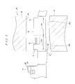
- FIG. 1 is a perspective view illustrative of a terminal to which a terminal crimping structure according to an aspect of the present invention is applied.
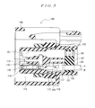
- FIG. 2 is a front cross-sectional view illustrative of the relationship between an anvil and a crimper included in a terminal crimping device according to an aspect of the present invention, and a wire barrel before a core wire is crimped.
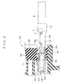
- FIG. 3 is a side surface partially cutaway cross-sectional view illustrative of the relationship between the anvil and the crimper included in the terminal crimping device illustrated in FIG. 2 , and the wire barrel after the core wire is crimped.
- FIG. 1 is a perspective view illustrative of a terminal to which a terminal crimping structure according to an aspect of the present invention is applied.
- FIG. 2 is a front cross-sectional view illustrative of the relationship between an anvil and a crimper included in a terminal crimping device according
- FIG. 4 is a perspective view illustrative of a terminal crimping structure according to an aspect of the present invention.
- the electrical wire that is crimped to the terminal is omitted.
- the core wire that is crimped to the wire barrel is omitted.
- a terminal crimping structure 1 is applicable to a terminal or the like included in an electrical connector.
- the terminal crimping structure 1 is applicable to any of a male terminal or a female terminal.
- a female terminal (terminal) 10 to which the terminal crimping structure 1 is applied is provided with: a receptacle portion 20; and an electrical wire connecting portion 30, as illustrated in FIG. 1 , and is formed by stamping and forming a metal plate.
- the female terminal 10 is connected to a contact carrier C in FIG. 1 , but is to be cut off from the contact carrier C after processing.
- the receptacle portion 20, as illustrated in FIG. 1 is formed to have a substantial box shape to receive a male contact (not illustrated) included in the mating connector (not illustrated).
- a retainer engaging portion 28 to be locked by a retainer (not illustrated), when the female terminal 10 is included in the electrical connector (not illustrated) is provided to protrude upward at a rear end portion, in the front-rear direction, of the upper surface of the receptacle portion 20 (the direction from the left near side to the right far side of FIG. 1 ).
- the left near side will be referred to as front side
- the right far side will be referred to as rear side.
- the electrical wire connecting portion 30, as illustrated in FIG. 1 is provided with: a wire barrel 31, which is arranged at the rear side of the receptacle portion 20 and which crimps the core wire S (refer to FIG. 2 ) of the electrical wire W (refer to FIG. 4 ); and an insulation barrel 32, which is arranged at the rear side of the wire barrel 31 and which crimps the insulation portion H of the electrical wire W.
- the wire barrel 31 includes a pair of side walls 34a and 34b that open upward.
- the wire barrel 31 also includes: an effective crimping portion 31a that crimps the core wire S of the electrical wire W; and an extending portion 31b that covers the end portion of the core wire S of the electrical wire W.
- the bottom surface of the wire barrel 31 is formed to extend as a straight line in the front-rear direction, connecting the effective crimping portion 31a and the extending portion 31b.
- upper end surfaces of the side walls 34a and 34b extend in parallel to the bottom surface of the wire barrel 31 extending in the front-rear direction.
- the effective crimping portion 31a swages both of the side walls 34a and 34b, thereby crimping the core wire S of the electrical wire W. In the state where the core wire S of the electrical wire W is crimped in the effective crimping portion 31a, desired electrical and mechanical properties are ensured at the crimped part where the effective crimping portion 31a and the core wire S are crimped.
- the extending portion 31b is arranged at the front side of the effective crimping portion 31a.
- the extending portion 31b covers the end portion of the core wire S of the electrical wire W by swaging both of the side walls 34a and 34b. In this case, the extending portion 31b does not crimp the core wire S of the electrical wire W.
- the extending portion 31b prevents the end portion of the core wire S from protruding frontward to be exposed from the wire barrel 31, with the core wire S of the electrical wire W crimped to the wire barrel 31.
- a confirmation hole 33 is arranged at the effective crimping portion 31a side of the extending portion 31b in the front-rear direction of the side walls 34a and 34b.
- the confirmation hole 33 is provided for confirming the position of the end portion of the core wire S in the wire barrel 31, with the core wire S of the electrical wire W crimped to the wire barrel 31. That is to say, the confirmation hole 33 permits confirming of the position of the end portion of the core wire S of the electrical wire W in the wire barrel 31 from the upper side thereof, with both of the side walls 34a and 34b of the extending portion 31b swaged.
- the insulation barrel 32 opens upward, and includes a pair of side walls 35a and 35b. The insulation barrel 32 crimps the insulation portion H of the electrical wire W by swaging both of the side walls 35a and 35b.
- the terminal crimping device 40 that crimps the electrical wire W to the female terminal 10 to form the terminal crimping structure 1.
- the terminal crimping device 40 as illustrated in FIG. 2 and FIG. 3 , is provided with: an anvil 41 on which the female terminal 10 is mounted; and a crimper 42 which presses the wire barrel 31 of the female terminal 10 mounted on the anvil 41 from the upper side (the upper side of FIG. 2 and FIG. 3 ).
- the upper surface of the anvil 41 is provided with a mounting groove 43, as illustrated in FIG. 2 , on which the female terminal 10 is mounted and which extends in the front-rear direction (the depth direction of FIG. 2 , the horizontal direction of FIG.3 ).
- the mounting groove 43 includes, as illustrated in FIG. 3 , a first pressing portion 43a that presses the effective crimping portion 31a; and a second pressing portion 43b that presses the extending portion 31b, in the wire barrel 31 of the female terminal 10 that is mounted.
- the bottom surface of the first pressing portion 43a, as illustrated in FIG. 3 is formed to extend horizontally, when viewed in the horizontal direction (the horizontal direction of FIG. 2 , the depth direction of FIG. 3 ).
- the bottom surface of the second pressing portion 43b is formed to be an inclined surface expanding and opening toward the receptacle portion 20 side when viewed in the horizontal direction, as illustrated in FIG. 3 .
- an angle ⁇ which is defined by an extension from the bottom surface of the second pressing portion 43b and another extension from the bottom surface of the first pressing portion 43a, not to exceed 45 degrees.
- the crimper 42 is arranged to be movable upward and downward with respect to the anvil 41.
- the bottom surface of the crimper 42 has a pressing groove 44 opposite to the mounting groove 43 of the anvil 41 with each other, as illustrated in FIG. 2 .
- the top surface of the pressing groove 44 is formed to extend in parallel to the first pressing portion 43a of the mounting groove 43 in the anvil 41, when viewed in the horizontal direction, as illustrated in FIG. 3 .
- the female terminal 10 is mounted on the mounting groove 43 of the anvil 41.
- the effective crimping portion 31a of the wire barrel 31 is disposed on the first pressing portion 43a, and simultaneously the extending portion 31b is disposed on the second pressing portion 43b.
- the bottom surface of the wire barrel 31 is formed to extend as a straight line in the front-rear direction, with connecting the effective crimping portion 31a and the extending portion 31b.
- the bottom surface of the second pressing portion 43b of the mounting groove 43 in the anvil 41 is formed to be an inclined surface expanding and opening toward the receptacle portion 20 side, when viewed in the horizontal direction. Accordingly, when the female terminal 10 is mounted on the mounting groove 43 of the anvil 41, the bottom surface of the effective crimping portion 31a and that of the first pressing portion 43a are brought into contact with each other, whereas the bottom surface of the extending portion 31b and that of the second pressing portion 43b create a gap therebetween.
- the electrical wire W is disposed on the female terminal 10.
- the core wire S of the electrical wire W is disposed on the wire barrel 31, and simultaneously the insulation portion H of the electrical wire W is disposed on the insulation barrel 32.
- the crimper 42 is made to move down as indicated by an arrow in FIG. 2 , so that the wire barrel 31 of the female terminal 10 disposed on the mounting groove 43 in the anvil 41 is pressed from the upper side thereof by the crimper 42. This permits both of the side walls 34a and 34b of the wire barrel 31 to be bent along the inner surface of the pressing groove 44 of the crimper 42.
- the female terminal 10 is mounted on the mounting groove 43 of the anvil 41, with the gap created between the bottom surface of the extending portion 31b in the wire barrel 31 and that of the second pressing portion 43b in the mounting groove 43.
- the pressing force which is produced when the crimper 42 presses the wire barrel 31 and which is exerted from the anvil 41 to the extending portion 31b, is smaller than that exerted from the anvil 41 to the effective crimping portion 31a. Accordingly, as the wire barrel 31 of the female terminal 10 mounted on the mounting groove 43 of the anvil 41 is pressed by the crimper 42 from the upper side thereof, the extending portion 31b of the wire barrel 31 is deformed toward the above-described gap side.
- both of the side walls 34a and 34b in the effective crimping portion 31a of the wire barrel 31 are swaged as illustrated in FIG. 4 , so the core wire S of the electrical wire W is crimped to the effective crimping portion 31a.
- both of the side walls 34a and 34b in the extending portion 31b of the wire barrel 31 are swaged as illustrated in FIG. 3 and FIG. 4 .
- the bottom surface of the extending portion 31b is deformed downward along the bottom surface of the second pressing portion 43b of the mounting groove 43, so a swelling portion 45 is produced at the lower part of the extending portion 31b. That is to say, the draft amount of the extending portion 31b in the wire barrel 31 is made smaller than that of the effective crimping portion 31a.
- the position of the end portion of the core wire S in the wire barrel 31 is confirmed from the confirmation hole 33 of the extending portion 31b. Then, in a case where the end portion of the core wire S is not located on the front side of the rear end portion of the confirmation hole 33, there is a possibility that the core wire S is not crimped over the entire area of the effective crimping portion 31a in the wire barrel 31, in the inserting/extracting direction (the horizontal direction of FIG. 3 ). This is judged to be a defective crimp.
- the pressing force exerted from the anvil 41 to the extending portion 31b is set smaller than that exerted from the anvil 41 to the effective crimping portion 31a. This allows the core wire S of the electrical wire W to be crimped only in the effective crimping portion 31a of the wire barrel 31, whereas the core wire S is not crimped in the extending portion 31b because the swelling portion 45 is formed at the lower part of the extending portion 31b.
- the terminal crimping device 40 makes it possible to suppress the pressing force to be needed for crimping the core wire S of the electrical wire W to the wire barrel 31, and to suppress the reaction force exerted from the wire barrel 31 to the anvil 41 and the crimper 42. Therefore, the terminal crimping device 40 makes it possible to suppress the generation of the abrasion at the anvil 41 and the crimper 42, and simultaneously to prevent the generation of the upthrust portion at the upper part of the wire barrel 31 to which the core wire S of the electrical wire W is crimped.
- the extending portion 31b of the wire barrel 31 covers the end portion of the core wire S of the electrical wire W, thereby preventing the end portion of the core wire S from extruding frontward to be exposed from the wire barrel 31. Therefore, with the terminal crimping structure 1, it is possible to prevent the end portion of the core wire S from damaging the sealing member, when the female terminal 10 is inserted into the sealing member included in a connector housing of collective waterproof type such as the connector housing 120 shown in FIG. 5 .
- the female terminal 10 having the terminal crimping structure 1 is included in an electrical connector, the female terminal 10 is secondarily locked by a retainer (not illustrated) to prevent the female terminal 10 from coming off from the connector housing (not illustrated). Then, when the female terminal 10 is locked by the retainer, the female terminal 10 is firstly inserted into the housing with the retainer disposed at a temporary locking position. In this case, the retainer is disposed above the wire barrel 31 of the female terminal 10 (the upper side of FIG. 3 ). Then, the retainer disposed at a temporary locking position is made to slide downward (to the lower side of FIG. 3 ) to be arranged at a proper locking position.
- the front surface of a locking part in the retainer locks the rear surface of the retainer engaging portion 28 of the female terminal 10 to prevent the female terminal 10 from moving rearward. Accordingly, in a state where the retainer is arranged at the proper locking position, a space that corresponds to a sliding amount of the retainer that has been made to slide from the temporary locking position to the proper locking position is inevitably created below the wire barrel 31 of the female terminal 10. Meanwhile, in the terminal crimping structure 1, the swelling portion 45 is produced at the lower part of the extending portion 31b. Accordingly, in a case where the female terminal 10 is applied to an electrical connector, the swelling portion 45 is accommodated in the space inevitably created below the wire barrel 31. For this reason, the swelling portion 45 does not interfere with the retainer.
- the female terminal 10 having the terminal crimping structure 1 it is made possible for the retainer to lock the female terminal 10 with certainty, even when the female terminal 10 is applied to an electrical connector in which the arrangement pitch between the terminals is made small. Furthermore, in an electrical connector (not illustrated) provided with the female terminals 10 each having the terminal crimping structure 1 and the connector housing (not illustrated) that secures the female terminals 10, the arrangement pitch between the female terminals 10 can be made small.
- a mounting groove of an anvil includes a first pressing portion that presses an effective crimping portion and a second pressing portion that presses an extending portion.
- the bottom surface of the second pressing portion is formed to be an inclined surface expanding and opening toward a receptacle portion side. This suppresses the generation of abrasion at the anvil and crimper, and simultaneously prevents the generation of an upthrust portion at the upper part of a wire barrel to which a core wire of an electrical wire is crimped.
- a terminal crimping structure is configured to produce a swelling portion at the lower part of the extending portion, thereby allowing a retainer to lock the terminal with certainty, even in a case where the terminal is applied to an electrical connector with a narrow arrangement pitch between the terminals.
- the electrical connector according to an aspect of the present invention is provided with terminals to which the above terminal crimping structure is applied, whereby the arrangement pitch between the terminals can be made small.
Landscapes
- Engineering & Computer Science (AREA)
- Manufacturing & Machinery (AREA)
- Connections Effected By Soldering, Adhesion, Or Permanent Deformation (AREA)
- Manufacturing Of Electrical Connectors (AREA)
Abstract
Description
- The present invention relates to a terminal crimping method, terminal crimping structure, terminal crimping device, and electrical connector having the terminal crimping structure, whereby a terminal which includes a wire barrel for crimping a core wire of an electrical wire is crimped to an end portion of the wire.
- Conventionally, an electrical connector shown in
FIG. 5 andFIG.6 have been known as inventions of the electric connector provided with the above-mentioned terminals (see Patent Document 1).FIG. 5 is a partially cutaway cross-sectional view showing a waterproof connector according to Patent Document 1.FIG. 6 is a partially cutaway cross-sectional view showing a terminal, which is being inserted into a cavity of the waterproof connector shown inFIG.5 . Awaterproof connector 100 shown inFIG. 5 andFIG. 6 includes multiple terminals 110 (only one terminal is shown inFIG. 5 andFIG. 6 ) and aconnector housing 120 in which theterminals 110 are accommodated. - Each
terminal 110 comprises areceptacle portion 111 and awire connecting portion 112, and is formed by stamping and forming a metal plate. Thereceptacle portion 111 is configured to have a substantial box shape to receive a tab provided at the mating connector (not shown). Thereceptacle portion 111 includes abase plate 113 that extends in the front-rear direction (the horizontal direction ofFIG. 5 ), a pair ofside walls 114 that stand up from both side edges in the widthwise direction (the direction perpendicular to the sheet face ofFIG. 5 ) of thebase plate 113, and anupper plate 115 that is bent from one of the pair ofside walls 114. - The
wire connecting portion 112 includes: awire barrel 116, which extends from the rear end of thebase plate 113 and which crimps a core wire S of an electrical wire W; and aninsulation barrel 117, which extends from the rear end of thewire barrel 116 and which crimps an insulation portion H of the electrical wire W. In this situation, in order to ensure electrical and mechanical connections, thewire barrel 116 needs to be crimped to the core wire S in the electrical wire W over the entire length in its inserting/extracting direction (the horizontal direction ofFIG. 5 ). Hence, the core wire S of the electrical wire W is crimped to thewire barrel 116 with its end portion T protruding frontward from thewire barrel 116. - The
connector housing 120 is provided withmultiple cavities 121 in two stages, namely upper and lower stages, into which theterminals 110 are accommodated, respectively. On the rear side ofmultiple cavities 121 in theconnector housing 120, there is provided a sealingmember fitting portion 123 into which a sealingmember 122 of family type is fit and inserted. The sealingmember 122 is provided with multiple throughholes 124 that communicate with thecavities 121, respectively. In addition, three lines oflips 125 are arranged at the inner circumferential surface in each of the throughholes 124. - Then, in the
waterproof connector 100 as shown inFIG. 6 , eachterminal 110 is inserted into eachcavity 121 from each throughhole 124 in thesealing member 122. This allows therespective lips 125 of thesealing member 122 to be tight around the electrical wire W of theterminal 110 that has been inserted into thethrough hole 124, thereby preventing a drop of water from entering the interior of thecavity 121 from the extracting side of the electrical wire W. - It should be noted, however, that in the
terminal 110 of thewaterproof connector 100, the end portion T of the core wire S of the electrical wire W that has been crimped by thewire barrel 116 protrudes frontward to be exposed from thewire barrel 116. Accordingly, in a case where the end portion T of the core wire S of the electrical wire W protrudes frontward to be exposed from thewire barrel 116, there is a problem that the end portion T will damage the sealingmember 122 when theterminal 110 is inserted into thethrough hole 124 of the sealingmember 122. Then, if the sealingmember 122 is damaged, tightness between the sealingmember 122 and the electrical wire W will be degraded. This will degrade the waterproof property in thecavity 121, when thewaterproof connector 100 mates with the mating connector. - Therefore, a terminal shown in
FIG. 7 has been proposed to address the above problem.FIG. 7 is a perspective view showing a terminal in which an end portion of a core wire is protected. Aterminal 130, in which an end portion of a core wire is protected, as shown inFIG. 7 , basically has the same configuration as that of theterminal 110, and is formed by stamping and forming a metal plate. However, aretainer engaging portion 137, to be locked by a retainer (not shown) when the core-wire end-portion protectedterminal 130 is included in an electrical connector (not shown), is provided at the upper surface of areceptacle portion 136 of the core-wire end-portion protectedterminal 130. - Also, a
wire barrel 131 of the core-wire end-portion protectedterminal 130 is provided with aneffective crimping portion 132 that crimps the core wire of the electrical wire W (not shown inFIG. 7 ), and an extendingportion 133 that covers the end portion of the core wire S of the electrical wire W. The extendingportion 133 is arranged on the front side of theeffective crimping portion 132. The extendingportion 133 is provided with aconfirmation hole 134. Theconfirmation hole 134 is provided for confirming the position of the end portion of the core wire in thewire barrel 131 with the core wire of the electrical wire W crimped to thewire barrel 131. Additionally, in the core-wire end-portion protectedterminal 130, theeffective crimping portion 132 of thewire barrel 131 crimps the core wire of the electrical wire W, and at the same time, the extendingportion 133 covers the end portion of the core wire. In this manner, the extendingportion 133 covers the end portion of the core wire of the electrical wire W, thereby preventing the end portion of the core wire from protruding frontward to be exposed from thewire barrel 131. - Accordingly, with the core-wire end-portion protected
terminal 130, it is possible to prevent the end portion of the core wire from damaging thesealing member 122, when the core-wire end-portion protectedterminal 130 is inserted into the sealing member provided in the connector housing of family waterproof type such as theconnector housing 120 shown inFIG. 5 . Moreover, after the crimping of the core wire of the electrical wire W to thewire barrel 131 is completed, the position of the end portion of the core wire in thewire barrel 131 is confirmed from theconfirmation hole 134 of the extendingportion 133. This makes it possible to confirm whether or not the core wire is crimped over the entire length in the inserting/extracting direction of the effective crimping portion 132 (the direction from the left near side to the right far side ofFIG. 7 ). In this case, the core wire of the electrical wire W is crimped to thewire barrel 131, by pressing thewire barrel 131 with an anvil and a crimper to swage thewire barrel 131 in which the core wire is arranged. - Meanwhile, the length of the
wire barrel 131 in the front-rear direction (the direction from the left near side to the right far side ofFIG. 7 ) in the core-wire end-portion protectedterminal 130 is longer than thewire barrel 116 in theterminal 110 shown inFIG. 6 by only the provision of the extendingportion 133 in its length. If thewire barrel 131 is longer, a greater pressing force is needed for swaging thewire barrel 131 when the core wire of the electric wire W is crimped. Next, if the pressing force exerted from the anvil and the crimper to thewire barrel 131 is greater, a reaction force exerted from thewire barrel 131 to the anvil and the crimper will be greater when the core wire of the electric wire W is crimped. Then, if the reaction force exerted to the anvil and the crimper is greater when the core wire of the electric wire W is crimped, there is a problem that abrasion will be caused with ease at the anvil and the crimper. - Hence, in order to address the above problem, the core wire of the electrical wire W is crimped to the
wire barrel 131 by aterminal crimping device 140 shown inFIG. 8. FIG. 8 is a partially cross-sectional view showing the relationship between a wire barrel of a terminal, and an anvil and a crimper included in the terminal crimping device.FIG. 8 shows a state where the crimping of the core wire of the electrical wire W to thewire barrel 131 is completed. That is to say, as shown inFIG. 8 , theterminal crimping device 140 is provided with ananvil 141 that supports thewire barrel 131 from the bottom side, and acrimper 142 that presses thewire barrel 131 from the top side. The lower surface of thecrimper 142 has apressing surface 143 that presses thewire barrel 131. As shown inFIG. 8 , thepressing surface 143 of thecrimper 142 has a portion for pressing the extendingportion 133, which is formed as aninclined surface 144 expanding and opening frontward. - When the core wire of the electrical wire (not shown in
FIG. 8 ) is crimped to thewire barrel 131 by theterminal crimping device 140, the extendingportion 133 of thewire barrel 131 is deformed along theinclined surface 144 of thepressing surface 143 in thecrimper 142 and then anupthrust portion 145 is formed. Thus, in theterminal crimping device 140, the core wire of the electrical wire W is crimped only to theeffective crimping portion 132 in thewire barrel 131, whereas the core wire is not crimped to the extendingportion 133 because theupthrust portion 145 is formed. Accordingly, with the use of theterminal crimping device 140, the pressing force needed for crimping the core wire of the electric wire W to thewire barrel 131 can be suppressed, so the reaction force exerted from thewire barrel 131 to theanvil 141 and thecrimper 142 can be suppressed. Therefore, theterminal crimping device 140 is capable of suppressing abrasion caused at theanvil 141 and thecrimper 142.
Patent Document 1:JP 2001-143807 A - In this sense, when the core-wire end-portion protected
terminal 130 is included in an electric connector, the core-wire end-portion protectedterminal 130 is secondarily locked by a retainer (not shown) to prevent the core-wire end-portion protectedterminal 130 from coming off from a connector housing (not shown). In such a case, the retainer is disposed above thewire barrel 131 of the core-wire end-portion protectedterminal 130, so the front surface of a locking portion (not shown) provided at the retainer locks the rear surface of theretainer engaging portion 137 of the core-wire end-portion protectedterminal 130, whereby the rearward movement of the core-wire end-portion protectedterminal 130 is prevented. Meanwhile, in recent years, there has been an increasing need for downsizing the electrical connector and increasing the number of terminals. In order to downsize the electrical connector and increase the number of terminals, it is necessary to make narrow the arrangement pitch between the terminals included in the electrical connector. - However, if the core-wire end-portion protected
terminal 130, in which the core wire of the electrical wire is crimped to thewire barrel 131 by theterminal crimping device 140, is applied to an electrical connector in which the arrangement pitch between the terminals is made narrow, theupthrust portion 145 will interfere with the retainer. Next, if theupthrust portion 145 interferes with the retainer, the retainer cannot be pushed to a predetermined position of the housing, resulting in an insufficient lock by means of the retainer for locking theretainer engaging portion 137 in the core-wire end-portion protectedterminal 130. Then, if the lock between the retainer and theretainer engaging portion 137 of the core-wire end-portion protectedterminal 130 is insufficient, there is a problem that a desired retaining force of the core-wire end-portion protectedterminal 130 will not be obtainable by means of the retainer. - Meanwhile, when the core-wire end-portion protected
terminal 130 is locked by the retainer, the core-wire end-portion protectedterminal 130 is inserted into the housing with the core-wire end-portion protectedterminal 130 disposed at a temporary locking position, firstly. In this case, the retainer is located above thewire barrel 131 of the core-wire end-portion protected terminal 130 (at the upper side ofFIG. 8 ). Subsequently, the retainer at the temporary locking position is made to slide downward (to the lower side ofFIG. 8 ) to be disposed at a proper locking position. In this case, the front surface of a engaging portion in the retainer locks the rear surface of theretainer engaging portion 137 of the core-wire end-portion protectedterminal 130 to prevent the core-wire end-portion protectedterminal 130 from moving rearward. Accordingly, in the sate where the retainer is located at the proper locking position, a space that corresponds to a sliding amount of the retainer that has been made to slide from the temporary locking position to the proper locking position is inevitably created below thewire barrel 131 of the core-wire end-portion protectedterminal 130. - The present invention has been made to solve the above problem, and has an object to provide a terminal crimping method and a terminal crimping device, thereby suppressing the generation of abrasion at an anvil and a crimper, and simultaneously preventing the formation of an upthrust portion at the upper part of a wire barrel to which a core wire of the electrical wire is crimped. In addition, it is another object of the present invention is to provide a terminal crimping structure in which a swelling portion is arranged at the lower part in the wire barrel to which the core wire of the electrical wire is crimped, thereby permitting a retainer to lock with certainty even in a case where the terminal is applied to an electrical connector with a narrow arrangement pitch between the terminals. Furthermore, it is yet another object of the present invention is to provide an electrical connector with terminals to which the above terminal crimping structure is applied, thereby permitting the arrangement pitch between the terminals to be made small.
- In order to address the above problems, according to an aspect of the present invention, there is provided a terminal crimping method including: mounting a terminal on a mounting groove of an anvil, the terminal including a receptacle portion, an effective crimping portion that crimps a core wire of an electrical wire, and a wire barrel having an extending portion that covers an end portion of the core wire; and pressing the wire barrel by use of a crimper, the mounting groove including a first pressing portion that presses the effective crimping portion and a second pressing portion that presses the extending portion, the bottom surface of the second pressing portion being formed to be an inclined surface expanding and opening toward the receptacle portion side.
- In addition, according to another aspect of the present invention, there is provided a terminal crimping structure including a terminal including: a receptacle portion having a retainer engaging portion that protrudes upward; an extending portion that covers an effective crimping portion that crimps a core wire of an electrical wire, and an end portion of the core wire; and a wire barrel that opens upward, wherein: the terminal is mounted on a mounting groove, the core wire of the electrical wire is crimped to the wire barrel by pressing the wire barrel by use of a crimper, the mounting groove includes a first pressing portion that presses the effective crimping portion and a second pressing portion that presses the extending portion, the bottom surface of the second pressing portion is formed to be an inclined surface expanding and opening toward the receptacle portion side, so a swelling portion is formed at a lower part of the extending portion.
- Furthermore, according to yet another aspect of the present invention, there is provided a terminal crimping device including: an anvil having a mounting surface on which a terminal is mounted, the terminal including a receptacle portion, and a wire barrel having an effective crimping portion that crimps a core wire of an electric wire and an extending portion that covers an end portion of the core; and a crimper that presses the wire barrel of the terminal mounted on the anvil, the mounting groove including a first pressing portion that presses the effective crimping portion and a second pressing portion that presses the extending portion, the bottom surface of the second pressing portion being formed to be an inclined surface expanding and opening toward the receptacle portion side. Moreover, there is provided an electrical connector including: a terminal having the above terminal crimping structure; and a housing that secures the terminal.
-
-
FIG. 1 is a perspective view illustrative of a terminal to which a terminal crimping structure according to an aspect of the present invention is applied; -
FIG. 2 is a front cross-sectional view illustrative of the relationship between an anvil and a crimper included in a terminal crimping device according to an aspect of the present invention, and a wire barrel before a core wire is crimped; -
FIG. 3 is a side surface partially cutaway cross-sectional view illustrative of the relationship between the anvil and the crimper included in the terminal crimping device illustrated inFIG. 2 , and the wire barrel after the core wire is crimped; -
FIG. 4 is a perspective view illustrative of a terminal crimping structure according to an aspect of the present invention; -
FIG. 5 is a partially cutaway cross-sectional view showing a waterproof connector according to Patent Document 1; -
FIG. 6 is a partially cutaway cross-sectional view showing a terminal, which is being inserted into a cavity of the waterproof connector shown inFIG.5 ; -
FIG. 7 is a perspective view showing a terminal in which an end portion of a core wire is protected; and -
FIG. 8 is a partially cross-sectional view showing the relationship between a wire barrel of a terminal, and - an anvil and a crimper included in the terminal crimping device.
-
- 1
- terminal crimping structure
- 10
- female terminal
- 20
- receptacle portion
- C
- contact carrier
- W
- electrical wire
- S
- core wire
- 28
- retainer engaging portion
- 30
- wire connecting portion
- 31
- wire barrel
- 31a
- effective crimping portion
- 31b
- extending portion
- 32
- insulation barrel
- 33
- confirmation hole
- 34a, 34b
- side walls
- 35a, 35b
- side walls
- 40
- terminal crimping device
- 41
- anvil
- 42
- crimper
- 43
- mounting groove
- 43a
- first pressing portion
- 43b
- second pressing portion
- 44
- pressing groove
- 45
- swelling portion
- The embodiments of the present invention will now be described with reference to the accompanying drawings.
FIG. 1 is a perspective view illustrative of a terminal to which a terminal crimping structure according to an aspect of the present invention is applied.FIG. 2 is a front cross-sectional view illustrative of the relationship between an anvil and a crimper included in a terminal crimping device according to an aspect of the present invention, and a wire barrel before a core wire is crimped.FIG. 3 is a side surface partially cutaway cross-sectional view illustrative of the relationship between the anvil and the crimper included in the terminal crimping device illustrated inFIG. 2 , and the wire barrel after the core wire is crimped.FIG. 4 is a perspective view illustrative of a terminal crimping structure according to an aspect of the present invention. Incidentally, inFIG. 3 , the electrical wire that is crimped to the terminal is omitted. Also, inFIG. 4 , the core wire that is crimped to the wire barrel is omitted. - A terminal crimping structure 1 according to an aspect of the present invention is applicable to a terminal or the like included in an electrical connector. In addition, the terminal crimping structure 1 is applicable to any of a male terminal or a female terminal. According to the present embodiment, a description will be given of a case where the terminal crimping structure 1 is applied to the female terminal for use in the electrical connector. A female terminal (terminal) 10 to which the terminal crimping structure 1 is applied is provided with: a
receptacle portion 20; and an electricalwire connecting portion 30, as illustrated inFIG. 1 , and is formed by stamping and forming a metal plate. Incidentally, thefemale terminal 10 is connected to a contact carrier C inFIG. 1 , but is to be cut off from the contact carrier C after processing. - The
receptacle portion 20, as illustrated inFIG. 1 , is formed to have a substantial box shape to receive a male contact (not illustrated) included in the mating connector (not illustrated). Aretainer engaging portion 28 to be locked by a retainer (not illustrated), when thefemale terminal 10 is included in the electrical connector (not illustrated) is provided to protrude upward at a rear end portion, in the front-rear direction, of the upper surface of the receptacle portion 20 (the direction from the left near side to the right far side ofFIG. 1 ). Hereinafter, the left near side will be referred to as front side, and the right far side will be referred to as rear side. - The electrical
wire connecting portion 30, as illustrated inFIG. 1 , is provided with: awire barrel 31, which is arranged at the rear side of thereceptacle portion 20 and which crimps the core wire S (refer toFIG. 2 ) of the electrical wire W (refer toFIG. 4 ); and aninsulation barrel 32, which is arranged at the rear side of thewire barrel 31 and which crimps the insulation portion H of the electrical wire W. Thewire barrel 31 includes a pair ofside walls wire barrel 31 also includes: an effective crimpingportion 31a that crimps the core wire S of the electrical wire W; and an extendingportion 31b that covers the end portion of the core wire S of the electrical wire W. Herein, the bottom surface of thewire barrel 31 is formed to extend as a straight line in the front-rear direction, connecting the effective crimpingportion 31a and the extendingportion 31b. Also, upper end surfaces of theside walls wire barrel 31 extending in the front-rear direction. The effective crimpingportion 31a swages both of theside walls portion 31a, desired electrical and mechanical properties are ensured at the crimped part where the effective crimpingportion 31a and the core wire S are crimped. - The extending
portion 31b is arranged at the front side of the effective crimpingportion 31a. The extendingportion 31b covers the end portion of the core wire S of the electrical wire W by swaging both of theside walls portion 31b does not crimp the core wire S of the electrical wire W. In addition, the extendingportion 31b prevents the end portion of the core wire S from protruding frontward to be exposed from thewire barrel 31, with the core wire S of the electrical wire W crimped to thewire barrel 31. Aconfirmation hole 33 is arranged at the effective crimpingportion 31a side of the extendingportion 31b in the front-rear direction of theside walls confirmation hole 33 is provided for confirming the position of the end portion of the core wire S in thewire barrel 31, with the core wire S of the electrical wire W crimped to thewire barrel 31. That is to say, theconfirmation hole 33 permits confirming of the position of the end portion of the core wire S of the electrical wire W in thewire barrel 31 from the upper side thereof, with both of theside walls portion 31b swaged. Theinsulation barrel 32 opens upward, and includes a pair ofside walls insulation barrel 32 crimps the insulation portion H of the electrical wire W by swaging both of theside walls - Next, a description will be given of a terminal crimping
device 40 that crimps the electrical wire W to thefemale terminal 10 to form the terminal crimping structure 1. Theterminal crimping device 40, as illustrated inFIG. 2 andFIG. 3 , is provided with: ananvil 41 on which thefemale terminal 10 is mounted; and acrimper 42 which presses thewire barrel 31 of thefemale terminal 10 mounted on theanvil 41 from the upper side (the upper side ofFIG. 2 andFIG. 3 ). The upper surface of theanvil 41 is provided with a mountinggroove 43, as illustrated inFIG. 2 , on which thefemale terminal 10 is mounted and which extends in the front-rear direction (the depth direction ofFIG. 2 , the horizontal direction ofFIG.3 ). - The mounting
groove 43 includes, as illustrated inFIG. 3 , a firstpressing portion 43a that presses the effective crimpingportion 31a; and a secondpressing portion 43b that presses the extendingportion 31b, in thewire barrel 31 of thefemale terminal 10 that is mounted. The bottom surface of the firstpressing portion 43a, as illustrated inFIG. 3 , is formed to extend horizontally, when viewed in the horizontal direction (the horizontal direction ofFIG. 2 , the depth direction ofFIG. 3 ). - The bottom surface of the second
pressing portion 43b is formed to be an inclined surface expanding and opening toward thereceptacle portion 20 side when viewed in the horizontal direction, as illustrated inFIG. 3 . Herein, it is possible to set an angle α, which is defined by an extension from the bottom surface of the secondpressing portion 43b and another extension from the bottom surface of the firstpressing portion 43a, not to exceed 45 degrees. Specifically, it is preferable to set the angle between 3 to 6 degrees. Thecrimper 42 is arranged to be movable upward and downward with respect to theanvil 41. The bottom surface of thecrimper 42 has apressing groove 44 opposite to the mountinggroove 43 of theanvil 41 with each other, as illustrated inFIG. 2 . The top surface of thepressing groove 44 is formed to extend in parallel to the firstpressing portion 43a of the mountinggroove 43 in theanvil 41, when viewed in the horizontal direction, as illustrated inFIG. 3 . - Next, a description will be given of an operation of crimping the electrical wire W to the
female terminal 10 by use of the terminal crimpingdevice 40 to form the terminal crimping structure 1. Firstly, as illustrated inFIG. 2 , thefemale terminal 10 is mounted on the mountinggroove 43 of theanvil 41. In this situation, the effective crimpingportion 31a of thewire barrel 31 is disposed on the firstpressing portion 43a, and simultaneously the extendingportion 31b is disposed on the secondpressing portion 43b. - Herein, the bottom surface of the
wire barrel 31 is formed to extend as a straight line in the front-rear direction, with connecting the effective crimpingportion 31a and the extendingportion 31b. On the other hand, the bottom surface of the secondpressing portion 43b of the mountinggroove 43 in theanvil 41 is formed to be an inclined surface expanding and opening toward thereceptacle portion 20 side, when viewed in the horizontal direction. Accordingly, when thefemale terminal 10 is mounted on the mountinggroove 43 of theanvil 41, the bottom surface of the effective crimpingportion 31a and that of the firstpressing portion 43a are brought into contact with each other, whereas the bottom surface of the extendingportion 31b and that of the secondpressing portion 43b create a gap therebetween. - Next, the electrical wire W is disposed on the
female terminal 10. In this situation, the core wire S of the electrical wire W is disposed on thewire barrel 31, and simultaneously the insulation portion H of the electrical wire W is disposed on theinsulation barrel 32. Then, thecrimper 42 is made to move down as indicated by an arrow inFIG. 2 , so that thewire barrel 31 of thefemale terminal 10 disposed on the mountinggroove 43 in theanvil 41 is pressed from the upper side thereof by thecrimper 42. This permits both of theside walls wire barrel 31 to be bent along the inner surface of thepressing groove 44 of thecrimper 42. - In this situation, as described above, the
female terminal 10 is mounted on the mountinggroove 43 of theanvil 41, with the gap created between the bottom surface of the extendingportion 31b in thewire barrel 31 and that of the secondpressing portion 43b in the mountinggroove 43. The pressing force, which is produced when thecrimper 42 presses thewire barrel 31 and which is exerted from theanvil 41 to the extendingportion 31b, is smaller than that exerted from theanvil 41 to the effective crimpingportion 31a. Accordingly, as thewire barrel 31 of thefemale terminal 10 mounted on the mountinggroove 43 of theanvil 41 is pressed by thecrimper 42 from the upper side thereof, the extendingportion 31b of thewire barrel 31 is deformed toward the above-described gap side. - Subsequently, when the
crimper 42 reaches the bottom dead center , both of theside walls portion 31a of thewire barrel 31 are swaged as illustrated inFIG. 4 , so the core wire S of the electrical wire W is crimped to the effective crimpingportion 31a. Meanwhile, when thecrimper 42 reaches the bottom dead center, both of theside walls portion 31b of thewire barrel 31 are swaged as illustrated inFIG. 3 andFIG. 4 . Also, at the same time, the bottom surface of the extendingportion 31b is deformed downward along the bottom surface of the secondpressing portion 43b of the mountinggroove 43, so a swellingportion 45 is produced at the lower part of the extendingportion 31b. That is to say, the draft amount of the extendingportion 31b in thewire barrel 31 is made smaller than that of the effective crimpingportion 31a. With this configuration, the core wire S of the electrical wire W is not crimped in the extendingportion 31b, but the end portion of the core wire S is covered. - Next, after the crimping of the core wire S of the electrical wire W to the
wire barrel 31 is completed, the position of the end portion of the core wire S in thewire barrel 31 is confirmed from theconfirmation hole 33 of the extendingportion 31b. Then, in a case where the end portion of the core wire S is not located on the front side of the rear end portion of theconfirmation hole 33, there is a possibility that the core wire S is not crimped over the entire area of the effective crimpingportion 31a in thewire barrel 31, in the inserting/extracting direction (the horizontal direction ofFIG. 3 ). This is judged to be a defective crimp. Conversely, in a case where the end portion of the core wire S is located on the front side of the rear end portion of theconfirmation hole 33, it is judged that crimping has been performed in an effective manner. As described heretofore, the terminal crimping structure 1 illustrated inFIG. 3 andFIG. 4 is formed. - In the manner, in the
terminal crimping device 40, the pressing force exerted from theanvil 41 to the extendingportion 31b is set smaller than that exerted from theanvil 41 to the effective crimpingportion 31a. This allows the core wire S of the electrical wire W to be crimped only in the effective crimpingportion 31a of thewire barrel 31, whereas the core wire S is not crimped in the extendingportion 31b because the swellingportion 45 is formed at the lower part of the extendingportion 31b. Accordingly, theterminal crimping device 40 makes it possible to suppress the pressing force to be needed for crimping the core wire S of the electrical wire W to thewire barrel 31, and to suppress the reaction force exerted from thewire barrel 31 to theanvil 41 and thecrimper 42. Therefore, theterminal crimping device 40 makes it possible to suppress the generation of the abrasion at theanvil 41 and thecrimper 42, and simultaneously to prevent the generation of the upthrust portion at the upper part of thewire barrel 31 to which the core wire S of the electrical wire W is crimped. - Additionally, in the terminal crimping structure 1, the extending
portion 31b of thewire barrel 31 covers the end portion of the core wire S of the electrical wire W, thereby preventing the end portion of the core wire S from extruding frontward to be exposed from thewire barrel 31. Therefore, with the terminal crimping structure 1, it is possible to prevent the end portion of the core wire S from damaging the sealing member, when thefemale terminal 10 is inserted into the sealing member included in a connector housing of collective waterproof type such as theconnector housing 120 shown inFIG. 5 . - Herein, when the
female terminal 10 having the terminal crimping structure 1 is included in an electrical connector, thefemale terminal 10 is secondarily locked by a retainer (not illustrated) to prevent the female terminal 10 from coming off from the connector housing (not illustrated). Then, when thefemale terminal 10 is locked by the retainer, thefemale terminal 10 is firstly inserted into the housing with the retainer disposed at a temporary locking position. In this case, the retainer is disposed above thewire barrel 31 of the female terminal 10 (the upper side ofFIG. 3 ). Then, the retainer disposed at a temporary locking position is made to slide downward (to the lower side ofFIG. 3 ) to be arranged at a proper locking position. In this situation, the front surface of a locking part in the retainer locks the rear surface of theretainer engaging portion 28 of thefemale terminal 10 to prevent the female terminal 10 from moving rearward. Accordingly, in a state where the retainer is arranged at the proper locking position, a space that corresponds to a sliding amount of the retainer that has been made to slide from the temporary locking position to the proper locking position is inevitably created below thewire barrel 31 of thefemale terminal 10. Meanwhile, in the terminal crimping structure 1, the swellingportion 45 is produced at the lower part of the extendingportion 31b. Accordingly, in a case where thefemale terminal 10 is applied to an electrical connector, the swellingportion 45 is accommodated in the space inevitably created below thewire barrel 31. For this reason, the swellingportion 45 does not interfere with the retainer. Therefore, with thefemale terminal 10 having the terminal crimping structure 1, it is made possible for the retainer to lock thefemale terminal 10 with certainty, even when thefemale terminal 10 is applied to an electrical connector in which the arrangement pitch between the terminals is made small. Furthermore, in an electrical connector (not illustrated) provided with thefemale terminals 10 each having the terminal crimping structure 1 and the connector housing (not illustrated) that secures thefemale terminals 10, the arrangement pitch between thefemale terminals 10 can be made small. - According to a terminal crimping method or a terminal crimping device, a mounting groove of an anvil includes a first pressing portion that presses an effective crimping portion and a second pressing portion that presses an extending portion. The bottom surface of the second pressing portion is formed to be an inclined surface expanding and opening toward a receptacle portion side. This suppresses the generation of abrasion at the anvil and crimper, and simultaneously prevents the generation of an upthrust portion at the upper part of a wire barrel to which a core wire of an electrical wire is crimped. In addition, a terminal crimping structure according to an aspect of the present invention is configured to produce a swelling portion at the lower part of the extending portion, thereby allowing a retainer to lock the terminal with certainty, even in a case where the terminal is applied to an electrical connector with a narrow arrangement pitch between the terminals. Furthermore, the electrical connector according to an aspect of the present invention is provided with terminals to which the above terminal crimping structure is applied, whereby the arrangement pitch between the terminals can be made small.
Claims (4)
- A terminal crimping method comprising:mounting a terminal on a mounting groove of an anvil, the terminal including a receptacle portion, an effective crimping portion that crimps a core wire of an electrical wire, and a wire barrel having an extending portion that covers an end portion of the core wire; andpressing the wire barrel by use of a crimper,the mounting groove including a first pressing portion that presses the effective crimping portion and a second pressing portion that presses the extending portion,the bottom surface of the second pressing portion being formed to be an inclined surface expanding and opening toward the receptacle portion side.
- A terminal crimping structure comprising a terminal including:a receptacle portion having a retainer engaging portion that protrudes upward;an extending portion that covers an effective crimping portion that crimps a core wire of an electrical wire, and an end portion of the core wire; anda wire barrel that opens upward,wherein:the terminal is mounted on a mounting groove,the core wire of the electrical wire is crimped to the wire barrel by pressing the wire barrel by use of a crimper,the mounting groove includes a first pressing portion that presses the effective crimping portion and a second pressing portion that presses the extending portion,the bottom surface of the second pressing portion is formed to be an inclined surface expanding and opening toward the receptacle portion side, so a swelling portion is formed at a lower part of the extending portion.
- A terminal crimping device comprising:an anvil having a mounting surface on which a terminal is mounted, the terminal including a receptacle portion, and a wire barrel having an effective crimping portion that crimps a core wire of an electric wire and an extending portion that covers an end portion of the core; anda crimper that presses the wire barrel of the terminal mounted on the anvil,the mounting groove including a first pressing portion that presses the effective crimping portion and a second pressing portion that presses the extending portion,the bottom surface of the second pressing portion being formed to be an inclined surface expanding and opening toward the receptacle portion side.
- An electrical connector comprising:a terminal having the terminal crimping structure according to claim 2; anda housing that secures the terminal.
Applications Claiming Priority (2)
| Application Number | Priority Date | Filing Date | Title |
|---|---|---|---|
| JP2007015539A JP4499114B2 (en) | 2007-01-25 | 2007-01-25 | Terminal crimping method, terminal crimping apparatus, terminal crimping structure, and electrical connector |
| PCT/JP2007/074374 WO2008090693A1 (en) | 2007-01-25 | 2007-12-19 | Terminal crimping method, terminal crimping structure, terminal crimping device, and electric connector |
Publications (3)
| Publication Number | Publication Date |
|---|---|
| EP2110901A1 true EP2110901A1 (en) | 2009-10-21 |
| EP2110901A4 EP2110901A4 (en) | 2012-07-18 |
| EP2110901B1 EP2110901B1 (en) | 2015-03-18 |
Family
ID=39644271
Family Applications (1)
| Application Number | Title | Priority Date | Filing Date |
|---|---|---|---|
| EP07859858.8A Active EP2110901B1 (en) | 2007-01-25 | 2007-12-19 | Terminal crimping method, terminal crimping structure, terminal crimping device, and electric connector |
Country Status (5)
| Country | Link |
|---|---|
| US (1) | US8167666B2 (en) |
| EP (1) | EP2110901B1 (en) |
| JP (1) | JP4499114B2 (en) |
| CN (1) | CN101647161B (en) |
| WO (1) | WO2008090693A1 (en) |
Cited By (2)
| Publication number | Priority date | Publication date | Assignee | Title |
|---|---|---|---|---|
| EP2738885A4 (en) * | 2011-07-26 | 2014-12-17 | Sumitomo Wiring Systems | CRIMPING MATRIX AND METHOD FOR MANUFACTURING ELECTRIC WIRE WITH TERMINAL TERMINAL |
| CN105191020A (en) * | 2013-03-19 | 2015-12-23 | 矢崎总业株式会社 | Crimp terminal and crimping structure for wire in crimp terminal |
Families Citing this family (28)
| Publication number | Priority date | Publication date | Assignee | Title |
|---|---|---|---|---|
| US9353734B2 (en) * | 2008-10-13 | 2016-05-31 | GM Global Technology Operations LLC | Active material elements having reinforced structural connectors |
| JP2011003363A (en) * | 2009-06-17 | 2011-01-06 | Hirose Electric Co Ltd | Crimp terminal structure, and terminal crimping device |
| JP4790851B2 (en) * | 2010-03-11 | 2011-10-12 | 株式会社 ピー・エル | Aluminum body connection structure and connector |
| CN101895022A (en) * | 2010-06-01 | 2010-11-24 | 鹤壁博昊机电有限公司 | Anti-breaking U-shaped joint for automobile electronic circuit |
| DE102010038465A1 (en) * | 2010-07-27 | 2012-02-02 | Robert Bosch Gmbh | Electrical connection |
| JP5684583B2 (en) * | 2010-11-26 | 2015-03-11 | 矢崎総業株式会社 | Electric wire and terminal connection structure and manufacturing method thereof |
| JP2013246886A (en) * | 2012-05-23 | 2013-12-09 | Auto Network Gijutsu Kenkyusho:Kk | Electric wire with terminal, method of manufacturing the same, and jig |
| JP5773218B2 (en) * | 2012-06-07 | 2015-09-02 | 住友電装株式会社 | Crimp terminal |
| JP5846114B2 (en) * | 2012-12-19 | 2016-01-20 | 住友電装株式会社 | Manufacturing method of electric wire with terminal and electric wire with terminal |
| WO2014129080A1 (en) * | 2013-02-22 | 2014-08-28 | 古河電気工業株式会社 | Crimp terminal, crimp connection structure, and method for manufacturing crimp connection structure |
| JP5920284B2 (en) * | 2013-05-17 | 2016-05-18 | 住友電装株式会社 | Electric wire with terminal |
| EP2919332B1 (en) * | 2014-03-10 | 2019-07-10 | Tyco Electronics France SAS | Electrical terminal and method for preparing a connector comprising such terminal |
| JP6302390B2 (en) * | 2014-10-03 | 2018-03-28 | 矢崎総業株式会社 | Electric wire with terminal |
| US9472885B2 (en) * | 2014-12-08 | 2016-10-18 | Delphi Technologies, Inc. | Electrical connector assembly with low terminal insertion force |
| JP6421737B2 (en) * | 2015-10-21 | 2018-11-14 | 株式会社オートネットワーク技術研究所 | Manufacturing method of electric wire with terminal, crimping jig, and electric wire with terminal |
| DE102016224796A1 (en) | 2015-12-16 | 2017-06-22 | Yazaki Corporation | Anschlussquetschvorrichtung |
| JP6387058B2 (en) * | 2015-12-16 | 2018-09-05 | 矢崎総業株式会社 | Terminal crimping device |
| JP2017117724A (en) * | 2015-12-25 | 2017-06-29 | 株式会社オートネットワーク技術研究所 | Manufacturing method for wire with terminal, crimp jig, and wire with terminal |
| WO2018013662A2 (en) * | 2016-07-12 | 2018-01-18 | Hubbell Incorporated | Electrical connector and die set with a connector guide |
| CN106026502B (en) * | 2016-07-14 | 2018-11-06 | 安徽美芝精密制造有限公司 | Connecting terminal, electric heating press, hot-press method, motor and compressor |
| JP6544412B2 (en) * | 2017-11-22 | 2019-07-17 | オムロン株式会社 | Connector terminals and connectors |
| JP6911727B2 (en) * | 2017-11-22 | 2021-07-28 | オムロン株式会社 | Connector terminals and connectors |
| JP6974135B2 (en) * | 2017-11-24 | 2021-12-01 | 矢崎総業株式会社 | Terminal connection method |
| EP3588679B1 (en) * | 2018-06-29 | 2023-09-27 | TE Connectivity Germany GmbH | Crimp and method for producing a crimp |
| JP6816074B2 (en) * | 2018-08-29 | 2021-01-20 | 株式会社オートネットワーク技術研究所 | Terminals and connectors |
| JP7283365B2 (en) * | 2019-12-13 | 2023-05-30 | 住友電装株式会社 | Wire with terminal |
| US11588255B2 (en) * | 2020-07-14 | 2023-02-21 | Yazaki Corporation | Electric wire with terminal having improved anticorrosion performance |
| JP1765486S (en) * | 2023-03-14 | 2024-03-13 | connector terminal |
Family Cites Families (11)
| Publication number | Priority date | Publication date | Assignee | Title |
|---|---|---|---|---|
| JPH0714658A (en) * | 1993-06-22 | 1995-01-17 | Sumitomo Wiring Syst Ltd | Terminal crimper device and terminal crimping method |
| JPH09306555A (en) * | 1996-05-20 | 1997-11-28 | Yazaki Corp | Crimp terminal and crimp terminal crimping device |
| JP2001143807A (en) | 1999-11-17 | 2001-05-25 | Sumitomo Wiring Syst Ltd | Terminal fitting for waterproof connector |
| JP3763574B2 (en) * | 2003-03-14 | 2006-04-05 | 日本航空電子工業株式会社 | connector |
| US6905376B2 (en) * | 2003-04-15 | 2005-06-14 | J.S.T. Mfg. Co., Ltd. | Terminal |
| US7419409B2 (en) * | 2003-06-18 | 2008-09-02 | Mitsubishi Cable Industries Ltd. | Connection terminal |
| JP2005183160A (en) * | 2003-12-19 | 2005-07-07 | Jst Mfg Co Ltd | Female contact |
| JP4520933B2 (en) * | 2005-11-18 | 2010-08-11 | 矢崎総業株式会社 | Terminal chain, crimper for crimping the terminal chain, terminal chain manufacturing method, and connection structure of a plurality of terminal fittings and a flat circuit body |
| JP2007149504A (en) * | 2005-11-28 | 2007-06-14 | Yazaki Corp | Female terminals and connectors |
| JP2007280850A (en) * | 2006-04-10 | 2007-10-25 | Sumitomo Wiring Syst Ltd | Terminal metal fitting |
| US7497721B2 (en) * | 2006-09-14 | 2009-03-03 | Tyco Electronics Corporation | Tool extractable contacts for electrical connectors |
-
2007
- 2007-01-25 JP JP2007015539A patent/JP4499114B2/en active Active
- 2007-12-19 CN CN2007800502400A patent/CN101647161B/en active Active
- 2007-12-19 EP EP07859858.8A patent/EP2110901B1/en active Active
- 2007-12-19 WO PCT/JP2007/074374 patent/WO2008090693A1/en not_active Ceased
- 2007-12-19 US US12/524,407 patent/US8167666B2/en active Active
Cited By (2)
| Publication number | Priority date | Publication date | Assignee | Title |
|---|---|---|---|---|
| EP2738885A4 (en) * | 2011-07-26 | 2014-12-17 | Sumitomo Wiring Systems | CRIMPING MATRIX AND METHOD FOR MANUFACTURING ELECTRIC WIRE WITH TERMINAL TERMINAL |
| CN105191020A (en) * | 2013-03-19 | 2015-12-23 | 矢崎总业株式会社 | Crimp terminal and crimping structure for wire in crimp terminal |
Also Published As
| Publication number | Publication date |
|---|---|
| US20110136397A1 (en) | 2011-06-09 |
| CN101647161B (en) | 2012-02-01 |
| JP2008181813A (en) | 2008-08-07 |
| EP2110901B1 (en) | 2015-03-18 |
| CN101647161A (en) | 2010-02-10 |
| JP4499114B2 (en) | 2010-07-07 |
| US8167666B2 (en) | 2012-05-01 |
| WO2008090693A1 (en) | 2008-07-31 |
| EP2110901A4 (en) | 2012-07-18 |
Similar Documents
| Publication | Publication Date | Title |
|---|---|---|
| EP2110901B1 (en) | Terminal crimping method, terminal crimping structure, terminal crimping device, and electric connector | |
| CN100566038C (en) | Female terminal fitting is used for the blank of several terminals joint and the method that forms female terminal fitting | |
| US7828581B2 (en) | Electrical connector with a retainer pressing the wire connecting portion of a wire terminal | |
| US8747156B2 (en) | Terminal fitting | |
| EP1986284A2 (en) | A connector and an assembling method therefor | |
| EP2151892B1 (en) | A terminal fitting and connecting method therefor | |
| EP1587171A1 (en) | A female terminal fitting and connector provided therewith | |
| EP2375512B1 (en) | Terminal fitting and production method therefor | |
| EP1936749A1 (en) | A terminal fitting, a connector and a forming method | |
| EP2375506A1 (en) | Terminal fitting connecting structure | |
| US11394136B2 (en) | Terminal | |
| US20100081325A1 (en) | Terminal fitting, a terminal fitting chain, a wire with a terminal fitting and a processing device therefor | |
| US11996644B2 (en) | Terminal | |
| US8403697B2 (en) | Space efficient lever connector | |
| EP2437357A1 (en) | Connector | |
| US8523619B2 (en) | Terminal fitting | |
| EP1981123A2 (en) | A terminal fitting and crimping method therefor | |
| US20150364835A1 (en) | Method of manufacturing connection structural body, connection structural body, wire harness, crimping member and crimping device | |
| EP1986288B1 (en) | A shorting terminal, a connector and an assembling method therefor | |
| CN104124557A (en) | Electrical terminal with a locking lance | |
| EP1689034B1 (en) | A terminal fitting, connector provided therewith and method of forming a terminal fitting | |
| EP1261075B1 (en) | A watertight connector and a method for mounting it | |
| EP1742300A1 (en) | A terminal fitting and a forming method therefor | |
| EP1693927A1 (en) | A terminal fitting, connector provided therewith and method of forming a terminal fitting | |
| EP2187478A1 (en) | A terminal fitting, a wire connection structure and a connecting method |
Legal Events
| Date | Code | Title | Description |
|---|---|---|---|
| PUAI | Public reference made under article 153(3) epc to a published international application that has entered the european phase |
Free format text: ORIGINAL CODE: 0009012 |
|
| 17P | Request for examination filed |
Effective date: 20090811 |
|
| AK | Designated contracting states |
Kind code of ref document: A1 Designated state(s): AT BE BG CH CY CZ DE DK EE ES FI FR GB GR HU IE IS IT LI LT LU LV MC MT NL PL PT RO SE SI SK TR |
|
| DAX | Request for extension of the european patent (deleted) | ||
| RAP1 | Party data changed (applicant data changed or rights of an application transferred) |
Owner name: TYCO ELECTRONICS JAPAN G.K. |
|
| A4 | Supplementary search report drawn up and despatched |
Effective date: 20120620 |
|
| RIC1 | Information provided on ipc code assigned before grant |
Ipc: H01R 4/18 20060101ALI20120614BHEP Ipc: H01R 43/048 20060101AFI20120614BHEP |
|
| GRAP | Despatch of communication of intention to grant a patent |
Free format text: ORIGINAL CODE: EPIDOSNIGR1 |
|
| INTG | Intention to grant announced |
Effective date: 20141014 |
|
| GRAS | Grant fee paid |
Free format text: ORIGINAL CODE: EPIDOSNIGR3 |
|
| GRAA | (expected) grant |
Free format text: ORIGINAL CODE: 0009210 |
|
| AK | Designated contracting states |
Kind code of ref document: B1 Designated state(s): AT BE BG CH CY CZ DE DK EE ES FI FR GB GR HU IE IS IT LI LT LU LV MC MT NL PL PT RO SE SI SK TR |
|
| REG | Reference to a national code |
Ref country code: GB Ref legal event code: FG4D |
|
| REG | Reference to a national code |
Ref country code: CH Ref legal event code: EP |
|
| REG | Reference to a national code |
Ref country code: IE Ref legal event code: FG4D |
|
| REG | Reference to a national code |
Ref country code: AT Ref legal event code: REF Ref document number: 717097 Country of ref document: AT Kind code of ref document: T Effective date: 20150415 |
|
| REG | Reference to a national code |
Ref country code: DE Ref legal event code: R096 Ref document number: 602007040725 Country of ref document: DE Effective date: 20150430 |
|
| REG | Reference to a national code |
Ref country code: SE Ref legal event code: TRGR |
|
| REG | Reference to a national code |
Ref country code: NL Ref legal event code: VDEP Effective date: 20150318 |
|
| REG | Reference to a national code |
Ref country code: NL Ref legal event code: VDEP Effective date: 20150318 |
|
| PG25 | Lapsed in a contracting state [announced via postgrant information from national office to epo] |
Ref country code: LT Free format text: LAPSE BECAUSE OF FAILURE TO SUBMIT A TRANSLATION OF THE DESCRIPTION OR TO PAY THE FEE WITHIN THE PRESCRIBED TIME-LIMIT Effective date: 20150318 Ref country code: FI Free format text: LAPSE BECAUSE OF FAILURE TO SUBMIT A TRANSLATION OF THE DESCRIPTION OR TO PAY THE FEE WITHIN THE PRESCRIBED TIME-LIMIT Effective date: 20150318 |
|
| REG | Reference to a national code |
Ref country code: AT Ref legal event code: MK05 Ref document number: 717097 Country of ref document: AT Kind code of ref document: T Effective date: 20150318 |
|
| REG | Reference to a national code |
Ref country code: LT Ref legal event code: MG4D |
|
| PG25 | Lapsed in a contracting state [announced via postgrant information from national office to epo] |
Ref country code: LV Free format text: LAPSE BECAUSE OF FAILURE TO SUBMIT A TRANSLATION OF THE DESCRIPTION OR TO PAY THE FEE WITHIN THE PRESCRIBED TIME-LIMIT Effective date: 20150318 Ref country code: GR Free format text: LAPSE BECAUSE OF FAILURE TO SUBMIT A TRANSLATION OF THE DESCRIPTION OR TO PAY THE FEE WITHIN THE PRESCRIBED TIME-LIMIT Effective date: 20150619 |
|
| PG25 | Lapsed in a contracting state [announced via postgrant information from national office to epo] |
Ref country code: NL Free format text: LAPSE BECAUSE OF FAILURE TO SUBMIT A TRANSLATION OF THE DESCRIPTION OR TO PAY THE FEE WITHIN THE PRESCRIBED TIME-LIMIT Effective date: 20150318 |
|
| PG25 | Lapsed in a contracting state [announced via postgrant information from national office to epo] |
Ref country code: SK Free format text: LAPSE BECAUSE OF FAILURE TO SUBMIT A TRANSLATION OF THE DESCRIPTION OR TO PAY THE FEE WITHIN THE PRESCRIBED TIME-LIMIT Effective date: 20150318 Ref country code: EE Free format text: LAPSE BECAUSE OF FAILURE TO SUBMIT A TRANSLATION OF THE DESCRIPTION OR TO PAY THE FEE WITHIN THE PRESCRIBED TIME-LIMIT Effective date: 20150318 Ref country code: PT Free format text: LAPSE BECAUSE OF FAILURE TO SUBMIT A TRANSLATION OF THE DESCRIPTION OR TO PAY THE FEE WITHIN THE PRESCRIBED TIME-LIMIT Effective date: 20150720 Ref country code: RO Free format text: LAPSE BECAUSE OF FAILURE TO SUBMIT A TRANSLATION OF THE DESCRIPTION OR TO PAY THE FEE WITHIN THE PRESCRIBED TIME-LIMIT Effective date: 20150318 Ref country code: CZ Free format text: LAPSE BECAUSE OF FAILURE TO SUBMIT A TRANSLATION OF THE DESCRIPTION OR TO PAY THE FEE WITHIN THE PRESCRIBED TIME-LIMIT Effective date: 20150318 Ref country code: ES Free format text: LAPSE BECAUSE OF FAILURE TO SUBMIT A TRANSLATION OF THE DESCRIPTION OR TO PAY THE FEE WITHIN THE PRESCRIBED TIME-LIMIT Effective date: 20150318 |
|
| PG25 | Lapsed in a contracting state [announced via postgrant information from national office to epo] |
Ref country code: PL Free format text: LAPSE BECAUSE OF FAILURE TO SUBMIT A TRANSLATION OF THE DESCRIPTION OR TO PAY THE FEE WITHIN THE PRESCRIBED TIME-LIMIT Effective date: 20150318 Ref country code: IS Free format text: LAPSE BECAUSE OF FAILURE TO SUBMIT A TRANSLATION OF THE DESCRIPTION OR TO PAY THE FEE WITHIN THE PRESCRIBED TIME-LIMIT Effective date: 20150718 Ref country code: AT Free format text: LAPSE BECAUSE OF FAILURE TO SUBMIT A TRANSLATION OF THE DESCRIPTION OR TO PAY THE FEE WITHIN THE PRESCRIBED TIME-LIMIT Effective date: 20150318 |
|
| REG | Reference to a national code |
Ref country code: FR Ref legal event code: PLFP Year of fee payment: 9 |
|
| REG | Reference to a national code |
Ref country code: DE Ref legal event code: R097 Ref document number: 602007040725 Country of ref document: DE |
|
| PLBE | No opposition filed within time limit |
Free format text: ORIGINAL CODE: 0009261 |
|
| STAA | Information on the status of an ep patent application or granted ep patent |
Free format text: STATUS: NO OPPOSITION FILED WITHIN TIME LIMIT |
|
| PG25 | Lapsed in a contracting state [announced via postgrant information from national office to epo] |
Ref country code: DK Free format text: LAPSE BECAUSE OF FAILURE TO SUBMIT A TRANSLATION OF THE DESCRIPTION OR TO PAY THE FEE WITHIN THE PRESCRIBED TIME-LIMIT Effective date: 20150318 |
|
| 26N | No opposition filed |
Effective date: 20151221 |
|
| PG25 | Lapsed in a contracting state [announced via postgrant information from national office to epo] |
Ref country code: SI Free format text: LAPSE BECAUSE OF FAILURE TO SUBMIT A TRANSLATION OF THE DESCRIPTION OR TO PAY THE FEE WITHIN THE PRESCRIBED TIME-LIMIT Effective date: 20150318 |
|
| PG25 | Lapsed in a contracting state [announced via postgrant information from national office to epo] |
Ref country code: BE Free format text: LAPSE BECAUSE OF NON-PAYMENT OF DUE FEES Effective date: 20151231 |
|
| PG25 | Lapsed in a contracting state [announced via postgrant information from national office to epo] |
Ref country code: MC Free format text: LAPSE BECAUSE OF FAILURE TO SUBMIT A TRANSLATION OF THE DESCRIPTION OR TO PAY THE FEE WITHIN THE PRESCRIBED TIME-LIMIT Effective date: 20150318 Ref country code: LU Free format text: LAPSE BECAUSE OF FAILURE TO SUBMIT A TRANSLATION OF THE DESCRIPTION OR TO PAY THE FEE WITHIN THE PRESCRIBED TIME-LIMIT Effective date: 20151219 |
|
| REG | Reference to a national code |
Ref country code: CH Ref legal event code: PL |
|
| GBPC | Gb: european patent ceased through non-payment of renewal fee |
Effective date: 20151219 |
|
| PG25 | Lapsed in a contracting state [announced via postgrant information from national office to epo] |
Ref country code: BE Free format text: LAPSE BECAUSE OF FAILURE TO SUBMIT A TRANSLATION OF THE DESCRIPTION OR TO PAY THE FEE WITHIN THE PRESCRIBED TIME-LIMIT Effective date: 20150318 |
|
| REG | Reference to a national code |
Ref country code: IE Ref legal event code: MM4A |
|
| PG25 | Lapsed in a contracting state [announced via postgrant information from national office to epo] |
Ref country code: LI Free format text: LAPSE BECAUSE OF NON-PAYMENT OF DUE FEES Effective date: 20151231 Ref country code: GB Free format text: LAPSE BECAUSE OF NON-PAYMENT OF DUE FEES Effective date: 20151219 Ref country code: IE Free format text: LAPSE BECAUSE OF NON-PAYMENT OF DUE FEES Effective date: 20151219 Ref country code: CH Free format text: LAPSE BECAUSE OF NON-PAYMENT OF DUE FEES Effective date: 20151231 |
|
| REG | Reference to a national code |
Ref country code: FR Ref legal event code: PLFP Year of fee payment: 10 |
|
| PG25 | Lapsed in a contracting state [announced via postgrant information from national office to epo] |
Ref country code: IT Free format text: LAPSE BECAUSE OF NON-PAYMENT OF DUE FEES Effective date: 20151219 |
|
| PG25 | Lapsed in a contracting state [announced via postgrant information from national office to epo] |
Ref country code: HU Free format text: LAPSE BECAUSE OF FAILURE TO SUBMIT A TRANSLATION OF THE DESCRIPTION OR TO PAY THE FEE WITHIN THE PRESCRIBED TIME-LIMIT; INVALID AB INITIO Effective date: 20071219 Ref country code: BG Free format text: LAPSE BECAUSE OF FAILURE TO SUBMIT A TRANSLATION OF THE DESCRIPTION OR TO PAY THE FEE WITHIN THE PRESCRIBED TIME-LIMIT Effective date: 20150318 |
|
| PG25 | Lapsed in a contracting state [announced via postgrant information from national office to epo] |
Ref country code: CY Free format text: LAPSE BECAUSE OF FAILURE TO SUBMIT A TRANSLATION OF THE DESCRIPTION OR TO PAY THE FEE WITHIN THE PRESCRIBED TIME-LIMIT Effective date: 20150318 |
|
| PG25 | Lapsed in a contracting state [announced via postgrant information from national office to epo] |
Ref country code: MT Free format text: LAPSE BECAUSE OF FAILURE TO SUBMIT A TRANSLATION OF THE DESCRIPTION OR TO PAY THE FEE WITHIN THE PRESCRIBED TIME-LIMIT Effective date: 20150318 Ref country code: TR Free format text: LAPSE BECAUSE OF FAILURE TO SUBMIT A TRANSLATION OF THE DESCRIPTION OR TO PAY THE FEE WITHIN THE PRESCRIBED TIME-LIMIT Effective date: 20150318 Ref country code: IT Free format text: LAPSE BECAUSE OF NON-PAYMENT OF DUE FEES Effective date: 20151219 |
|
| PGRI | Patent reinstated in contracting state [announced from national office to epo] |
Ref country code: IT Effective date: 20170710 |
|
| REG | Reference to a national code |
Ref country code: FR Ref legal event code: PLFP Year of fee payment: 11 |
|
| PGFP | Annual fee paid to national office [announced via postgrant information from national office to epo] |
Ref country code: FR Payment date: 20201112 Year of fee payment: 14 |
|
| PG25 | Lapsed in a contracting state [announced via postgrant information from national office to epo] |
Ref country code: FR Free format text: LAPSE BECAUSE OF NON-PAYMENT OF DUE FEES Effective date: 20211231 |
|
| PGFP | Annual fee paid to national office [announced via postgrant information from national office to epo] |
Ref country code: DE Payment date: 20250930 Year of fee payment: 19 |
|
| PGFP | Annual fee paid to national office [announced via postgrant information from national office to epo] |
Ref country code: IT Payment date: 20251121 Year of fee payment: 19 |
|
| PGFP | Annual fee paid to national office [announced via postgrant information from national office to epo] |
Ref country code: SE Payment date: 20251001 Year of fee payment: 19 |