EP2110713A2 - Powder developer holding apparatus, developing apparatus, and image forming apparatus - Google Patents
Powder developer holding apparatus, developing apparatus, and image forming apparatus Download PDFInfo
- Publication number
- EP2110713A2 EP2110713A2 EP09153426A EP09153426A EP2110713A2 EP 2110713 A2 EP2110713 A2 EP 2110713A2 EP 09153426 A EP09153426 A EP 09153426A EP 09153426 A EP09153426 A EP 09153426A EP 2110713 A2 EP2110713 A2 EP 2110713A2
- Authority
- EP
- European Patent Office
- Prior art keywords
- shutter
- powder developer
- discharging opening
- holding apparatus
- developer holding
- Prior art date
- Legal status (The legal status is an assumption and is not a legal conclusion. Google has not performed a legal analysis and makes no representation as to the accuracy of the status listed.)
- Granted
Links
- 239000000843 powder Substances 0.000 title claims abstract description 35
- 238000007599 discharging Methods 0.000 claims abstract description 62
- 230000005484 gravity Effects 0.000 description 4
- 238000004140 cleaning Methods 0.000 description 2
- 238000012986 modification Methods 0.000 description 2
- 230000004048 modification Effects 0.000 description 2
- 239000002245 particle Substances 0.000 description 2
- 230000002093 peripheral effect Effects 0.000 description 2
- 238000007789 sealing Methods 0.000 description 2
- 239000003086 colorant Substances 0.000 description 1
- 230000008878 coupling Effects 0.000 description 1
- 238000010168 coupling process Methods 0.000 description 1
- 238000005859 coupling reaction Methods 0.000 description 1
- 239000000463 material Substances 0.000 description 1
Images


Classifications
-
- G—PHYSICS
- G03—PHOTOGRAPHY; CINEMATOGRAPHY; ANALOGOUS TECHNIQUES USING WAVES OTHER THAN OPTICAL WAVES; ELECTROGRAPHY; HOLOGRAPHY
- G03G—ELECTROGRAPHY; ELECTROPHOTOGRAPHY; MAGNETOGRAPHY
- G03G15/00—Apparatus for electrographic processes using a charge pattern
- G03G15/06—Apparatus for electrographic processes using a charge pattern for developing
- G03G15/08—Apparatus for electrographic processes using a charge pattern for developing using a solid developer, e.g. powder developer
- G03G15/0822—Arrangements for preparing, mixing, supplying or dispensing developer
- G03G15/0877—Arrangements for metering and dispensing developer from a developer cartridge into the development unit
- G03G15/0881—Sealing of developer cartridges
- G03G15/0886—Sealing of developer cartridges by mechanical means, e.g. shutter, plug
-
- G—PHYSICS
- G03—PHOTOGRAPHY; CINEMATOGRAPHY; ANALOGOUS TECHNIQUES USING WAVES OTHER THAN OPTICAL WAVES; ELECTROGRAPHY; HOLOGRAPHY
- G03G—ELECTROGRAPHY; ELECTROPHOTOGRAPHY; MAGNETOGRAPHY
- G03G15/00—Apparatus for electrographic processes using a charge pattern
- G03G15/06—Apparatus for electrographic processes using a charge pattern for developing
- G03G15/08—Apparatus for electrographic processes using a charge pattern for developing using a solid developer, e.g. powder developer
- G03G15/0822—Arrangements for preparing, mixing, supplying or dispensing developer
- G03G15/0848—Arrangements for testing or measuring developer properties or quality, e.g. charge, size, flowability
- G03G15/0849—Detection or control means for the developer concentration
- G03G15/0855—Detection or control means for the developer concentration the concentration being measured by optical means
-
- G—PHYSICS
- G03—PHOTOGRAPHY; CINEMATOGRAPHY; ANALOGOUS TECHNIQUES USING WAVES OTHER THAN OPTICAL WAVES; ELECTROGRAPHY; HOLOGRAPHY
- G03G—ELECTROGRAPHY; ELECTROPHOTOGRAPHY; MAGNETOGRAPHY
- G03G15/00—Apparatus for electrographic processes using a charge pattern
- G03G15/06—Apparatus for electrographic processes using a charge pattern for developing
- G03G15/08—Apparatus for electrographic processes using a charge pattern for developing using a solid developer, e.g. powder developer
- G03G15/0822—Arrangements for preparing, mixing, supplying or dispensing developer
- G03G15/0865—Arrangements for supplying new developer
-
- G—PHYSICS
- G03—PHOTOGRAPHY; CINEMATOGRAPHY; ANALOGOUS TECHNIQUES USING WAVES OTHER THAN OPTICAL WAVES; ELECTROGRAPHY; HOLOGRAPHY
- G03G—ELECTROGRAPHY; ELECTROPHOTOGRAPHY; MAGNETOGRAPHY
- G03G2215/00—Apparatus for electrophotographic processes
- G03G2215/06—Developing structures, details
- G03G2215/066—Toner cartridge or other attachable and detachable container for supplying developer material to replace the used material
- G03G2215/0663—Toner cartridge or other attachable and detachable container for supplying developer material to replace the used material having a longitudinal rotational axis, around which at least one part is rotated when mounting or using the cartridge
- G03G2215/0665—Generally horizontally mounting of said toner cartridge parallel to its longitudinal rotational axis
- G03G2215/067—Toner discharging opening covered by arcuate shutter
Definitions
- the present invention relates to a powder developer, a developing apparatus, and an image forming apparatus.
- a printer includes image forming units.
- the image forming unit includes a photoconductive drum, a charging roller, and a developing unit.
- the charging roller uniformly charges the surface of the photoconductive drum.
- An LED head illuminates the charged surface of the photoconductive drum in accordance with image data to form an electrostatic latent image on the photoconductive drum.
- a thin layer of toner is formed on the developing roller, and the toner on the developing roller is supplied to the electrostatic latent image to form a toner image on the photoconductive drum.
- the toner image is then transferred by a transfer roller onto a print medium or paper.
- the toner image on the print medium is then fixed into a permanent image.
- JP 2003-50505A discloses a printer in which a powder developer holding apparatus or a toner cartridge is detachably attached to the image forming unit. Toner is supplied from the toner cartridge into a developing unit.
- the toner cartridge includes a toner discharging opening formed therein, the discharging opening being opened and closed by a shutter with an operation lever. When the lever is operated to an opening position, the shutter opens the toner discharging opening such that the toner is discharged from the toner cartridge.
- the toner cartridge suffers from a problem in that the shutter may be opened with the toner discharging opening facing upward, before the toner cartridge has been attached to the image forming unit. If the shutter is opened inadvertently, foreign matter (e.g., paper particles) may enter the toner cartridge.
- foreign matter e.g., paper particles
- An object of the invention is to solve the drawbacks of conventional image forming apparatuses.
- Another object of the invention is to provide a developer holding apparatus in which foreign matter is prevented from entering the developer holding apparatus.
- Still another object of the invention is to provide a developing unit that employs the developer holding apparatus and an image forming apparatus that employs the developing unit.
- a powder developer holding apparatus is capable of preventing powder developer from leaking.
- a housing (43) holds powder developer and includes a discharging opening (44) through which the powder developer is discharged.
- a shutter (42) is mounted to the housing (43) and is rotatable relative to the housing (43) to an opening position where the discharging opening (44) is opened or to a closing position where the discharging opening (44) is closed.
- a locking member (54, 69) is slidably mounted to said shutter (42), and prevents the shutter from rotating relative to the housing when the powder developer holding apparatus is oriented such that the discharging opening (44) faces upward in a gravitational direction.
- a developing apparatus incorporates the powder developer holding apparatus of the aforementioned configuration.
- An image forming apparatus incorporates the powder developer holding apparatus of the aforementioned configuration.
- Fig. 1 illustrates the general configuration of a printer of a first embodiment.
- a medium holder or a paper cassette 11 is disposed at a lower portion of the printer.
- the paper cassette 11 holds a stack of print media (e.g., print paper, not shown).
- a paper feeding mechanism is disposed adjacent to the front end of the paper cassette 11, and includes a feed roller 12 and a separator roller 13. The paper feeding mechanism feeds the print paper on a page-by-page basis in to a transport path.
- the print paper is fed to a transport roller 14 and then to a transport roller 15, so that the print paper advances through image forming units (referred to as ID unit hereinafter) 16BK, 16Y, 16M, and 16C that form black, yellow, magenta, and cyan toner images, respectively.
- ID unit image forming units
- the ID units 16BK, 16Y, 16M, and 16C include image bearing bodies or photoconductive drums 31Bk, 31Y, 31M, and 31C, respectively. Disposed around the photoconductive drums 31Bk, 31Y, 31M, and 31C are exposing units or LED heads 22BK, 22Y, 22M, and 22C, respectively, which extend in parallel to the photoconductive drums 31BK, 31Y, 31M, and 31C.
- the exposing units may also be a laser type exposing unit.
- a transfer unit is disposed to face the ID units 16BK, 16Y, 16M, and 16C.
- the transfer unit includes a drive roller R1, a driven roller R2, a transport belt 17 disposed about the drive roller R1 and driven roller R2, and transfer rollers 21BK, 21Y, 21M, and 21C.
- the drive roller R1 drives the transport belt 17 to run.
- the transfer rollers 21K, 21Y, 21M, and 21C parallel the photoconductive drums 31BK, 31Y, 31M, and 31C, respectively, with the transport belt 17 sandwiched between the photoconductive drums 31BK, 31Y, 31M, and 31C and the transfer rollers 21BK, 21Y, 21M, and 21C.
- the transport belt 17 runs in a direction shown by arrow Q to transport the print paper through the respective ID units 16BK, 16Y, 16M, and 16C so that the toner images of the respective colors are transferred onto the print paper in registration to form a full color toner image.
- the print paper is advanced to a fixing unit 36 where the full color toner image is fixed into a full color permanent image. Then, the print paper is further advanced by a transport roller 19 from the fixing unit 36, and then by a discharge roller 20 onto a stacker outside of the printer.
- the ID units 16BK, 16Y, 16M, and 16C will be described. Each of the ID units 16BK, 16Y, 16M, and 16C may be substantially identical; for simplicity only the operation of the ID unit 16BK for forming black images will be described, it being understood that the other ID units 16BK, 16Y, 16M, and 16C may work in a similar fashion.
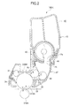
- Fig. 2 is a cross-sectional view of the ID unit 16BK of the first embodiment.
- a toner cartridge 41 is detachably attached to a body 37 of the ID unit 16BK (powder developer holding apparatus).
- the toner cartridge 41 holds black powder developer or toner (not shown), which is supplied into the body 37.
- the toner cartridge 41 includes a housing or a case 43 in which a discharging opening 44 is formed.
- a shutter 42 is attached into the case 43 such that the shutter 42 is slidably movable along a substantially cylindrical inner wall of the case 43 to open or close the discharging opening 44 and is rotatable about its longitudinal axis.
- the shutter 42 includes an opening 42a formed therein.
- Fig. 2 illustrates the shutter position when the shutter closes the discharging opening 44.
- the body 37 includes a concavely cylindrical mounting surface for receiving the toner cartridge 41 thereon.
- the mounting surface is formed with a developer receiving opening 45 therein. The toner discharged from the toner cartridge 41 is received into the body 37 through the developer receiving opening 45.
- the ID unit 16BK includes a photoconductive drum 31BK, a charging roller 32, a developing roller 33, a toner supplying roller 34, a developing blade 35, and a cleaning blade 36.
- the charging roller 32 uniformly charges the surface of the photoconductive drum 31BK.
- the toner supplying roller 34 supplies the toner to the developing roller 33.
- the developing blade 35 forms a thin layer of toner on the developing roller 33.
- the developing roller 33 holds the thin layer of toner thereon.
- the cleaning blade 36 removes the residual toner from the surface of the photoconductive drum 31BK.
- a drive motor (not shown) drives the developing roller 33 and the toner supplying roller 34 in directions shown by arrows C and B, respectively, during printing, so that the toner is supplied from the toner supplying roller 34 to the developing roller 33.
- the developing roller 33 rotates, the developing blade 35 in pressure contact with the developing roller 36 forms the thin layer of toner on the developing roller 33, removing excess toner from the developing roller 33.
- the thin layer of toner is brought into contact with the photoconductive drum 31BK.
- the photoconductive drum 31BK is driven by a drive motor (not shown) to rotate in a direction shown by arrow A.
- the surface of the photoconductive drum 31BK is uniformly charged by the charging roller 32.
- the LED head 22BK illuminates the charged surface of the photoconductive drum 31BK to form an electrostatic latent image in accordance with print data.
- the electrostatic latent image is developed with the toner supplied from the thin layer of toner formed on the developing roller 33.
- FIG. 3A is a perspective exploded view of the toner cartridge 41 of the first embodiment.
- Figs. 3B and 3C are perspective views of the shutter.
- Fig. 4 illustrates the toner cartridge 41 when an operation lever 63 is at a closing position and
- Fig. 5 illustrates the toner cartridge 41 when the operation lever 63 is at an opening position.
- the toner cartridge 41 includes the case 43 and the shutter 42 detachably attached to the case 43.
- the case 43 includes a generally cylindrical lower bottom 43a in which the toner discharging opening 44 is formed.
- the shutter 42 is generally in the shape of a hollow cylinder.
- the shutter 42 includes a body 81, a knob 92 that fits over one end portion of the body 81 ( Fig. 3A ).
- the knob 92 includes a short cylindrical portion 82 that fits to the body 81 such that the shutter 42 is rotatable together with the knob 92 relative to the body 81.
- the knob 92 includes the operation lever 63 that extends radially from the knob 92.
- the knob 92 also includes three radial projections ( Figs.
- the body 81 includes a shutter portion 42c that closes the discharging opening 44 and an opening 42a that opens the discharging opening 44.
- the body 81 also includes three recesses to which the three radial projections of the knob 92 fits so that the knob 92 and the body 81 are unable to rotate relative to each other but are able to rotate together.
- the shutter portion 42c and opening 42a extend in a direction parallel to a longitudinal direction of the body 81.
- a sealing member 42d is formed of, for example, a sponge material, and is bonded to the outer circumferential surface adjacent to the opening 42a.
- the sealing member 42d seals the gap between the shutter 42 and the case 43 to prevent the toner from leaking from the case 43.
- the operation lever 63 is in one piece with the shutter 42, and extends in a radial direction from the knob 92.
- the case 43 includes a side wall 43b from which a guide portion 43c projects outwardly. The guide portion 43c guides the shutter 42 into the case 43 when the shutter 42 is inserted into the case 43.
- the toner cartridge 41 includes a rotation limiting mechanism that is disposed between the case 43 and the shutter 42 and limits rotation of the shutter 42 relative to the toner cartridge 41.
- the rotation limiting mechanism includes a stopper or a projection 51 and a locking element or a pin 54.
- the projection 51 projects from the side wall 43b in the vicinity of the guide portion 43c.
- the pin 54 which will be described later, is disposed on the shutter 42.
- the projection 51 is substantially rectangular in the first embodiment, but may be in any shape.
- Figs. 6 and 7 are a first cross-sectional view and a second cross-sectional view, respectively, illustrating a pertinent portion of the toner cartridge 41 when the toner cartridge 41 has been attached to the body 37.
- Figs. 8 and 9 are a first cross-sectional view and a second cross-sectional view, respectively, illustrating a pertinent portion of the toner cartridge 41 when the toner cartridge 41 has been detached from the body 37.
- Figs. 6-9 illustrate the portions that project outwardly from the side wall 43b, and therefore do not illustrate the discharging opening 44 and opening 42a.
- Figs. 6-9 illustrate cross-sectional views of a portion of the shutter 42 between the operation lever 63 and the side wall 43b, and therefore do not show the lever 63.
- the case 43 includes the bottom surface 43a that extends in a longitudinal direction of the toner cartridge 41 and a guide portion 43c that projects from the side wall 43b.
- the short cylindrical portion 82 includes a radial extension 85.
- Projections 85a and 85b extend from the knob 92 substantially in a radial direction.
- An arcuate wall 85c extends across the projections 85a and 85b through a predetermined angular range ⁇ with respect to the rotational axis of the shutter 42. Referring to Fig. 6 , the projection 85a is formed at a position substantially in a gravitational direction, and the projection 85b is formed at a position a predetermined angle away from the projection 85a.
- the projections 85a and 85b and the arcuate wall 85c cooperate to define a moveable range ⁇ in which the shutter 42 may rotate. When the user operates the operation lever 63, the shutter 42 rotates within the movable range ⁇ .
- the arcuate wall 85c includes a step 85d that serves as a first stopper.
- the projection 85b serves as a second stopper.
- a stopper or a projection 43d projects outwardly from the side wall 43b in a direction substantially parallel to the longitudinal axis of the toner cartridge 41.
- a stopper or projection 43e also projects from one end of the bottom surface 43a.
- a recess 53 is formed in the body 81 at a position to which the body 81 is rotated from a position in a gravitational direction through 25 degrees approximately.
- the pin 54 is received in the recess 53 such that the pin 54 is slidable due to gravity in the recess 53.
- a stopper surface 55 is formed at a position such that the stopper surface 55 faces the recess 53.
- the pin 54 has a length such that when the toner cartridge 41 has been attached to the body 37 of the ID unit 16BK and therefore the discharging opening 44 faces downward, the pin 54 is completely received in the recess 53 and will not project outwardly from the recess 53. Thus, the shutter 42 is allowed to rotate between the opening position where the discharging opening 44 is opened and the closing position where the discharging opening 44 is closed.
- the pin 54 extends to a first position or an extended position from the recess 53 due to gravity, and abuts the stopper surface 55 as shown in Figs. 8 and 9 .
- the projection 51 projects from the side wall 43b in a direction parallel to a direction in which the case 43 extends, being disposed in the vicinity of the guide portion 43c of the case 43.
- the pin 54 is slidably received in the recess 53 formed in the body 81 of the shutter 42.
- the pin 54 retracts into the recess 53 so that the pin 54 will move to a second position or retracted position where the pin 54 is out of engagement with the pin 51 to allow the shutter 42 rotate to the opening position.
- the projection 51 is disposed in the vicinity of an upper portion of the guide portion 43c in the gravitational direction, the projection may be disposed any position as long as the discharging opening 44 will not open when the pin 54 abuts the projection 51.
- Fig. 10 is a perspective exploded view of a toner cartridge 41 of a second embodiment.
- Fig. 11 illustrates the toner cartridge 41 when an operation lever 63 is at a closing position where a shutter 42 closes a discharging opening 44 of a toner cartridge 41
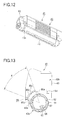
- Fig. 12 illustrates the toner cartridge 41 when the operation lever 63 is at an opening position where the shutter 42 opens the discharging opening 44 of the toner cartridge 41.
- An arcuate groove 65 is formed in the bottom surface 43a of the case 43 in the vicinity of one longitudinal end of the case 43.
- a projection 92a is slidable only in the groove 65 so that the knob 92 is prevented from being pulled out of engagement with a first portion or a body 91 of the shutter 42.
- the projection 92a is formed on an outer surface of a second portion or a knob 92, being received in the arcuate groove 65 from inside of the case 43.
- the groove 65 may also serve as a means for defining an extent in which the knob 92 is rotatable relative to the body 91, and ends 65a and 65b of the groove 65 serve as stoppers, respectively, that limit the extent in which the shutter 42 is moved when the operation lever 63 is operated.
- the toner cartridge 41 includes a case 43 having a bottom surface 43a in the shape of a partial cylinder.
- a discharging opening 44 is formed in the bottom surface 43a.
- the shutter 42 is generally in the shape of a hollow cylinder, and mounted to the bottom surface 43a. The shutter 42 is movable to the opening position where the shutter 42 opens the discharging the opening 44, and to the closing position where the shutter 42 closes the discharging opening 44.
- the shutter 42 includes a shutter portion and an opening 42a.
- the shutter 42 includes a first portion or a body 91 that extends over the entire length of the case 43, and a second portion or knob 92 that detachably slidably fits over a sliding surface 91a formed at one longitudinal end portion of the shutter 42.
- the knob 92 is selectively locked to the shutter 42 by means of locking member or a pin 69, which will be described later, when the pin 69 moves relative to the shutter and the knob 92.
- the body 91 includes the sliding surface 91a over which the knob 92 fits, a shutter portion 42c that closes the discharging opening 44, and an opening 42a that opens the discharging opening 44.
- An operation lever 63 is in one piece with the knob 92, and extends radially outwardly from the knob 92.
- the shutter 42 rotates to open or close the discharging opening 44.
- Figs. 13 and 14 are a first cross-sectional view and a second cross-sectional view, respectively, illustrating a pertinent portion of the toner cartridge 41 when the toner cartridge 41 has been attached to a body 37 of an ID unit 16BK.
- Fig. 13 illustrates a radial extension 85 when it is at the closing position.
- a projection 85b abuts a stopper or a projection 43e.
- Fig. 14 illustrates the radial extension 85 when it is at the opening position.
- a projection 85a abuts a stopper or a projection 43d.
- the short cylindrical portion 92 includes the radial extension 85.
- the radial extension 85 includes the projections 85a and 85b extending from the short cylindrical portion 92 in a substantially radial direction.
- An arcuate wall 85c extends across the projections 85a and 85b across a predetermined angular range ⁇ ( Fig. 13 ) with respect to the rotational axis of the shutter 42.
- the radial extension 85 defines angular range in which the shutter 42 may rotate. When the user operates the operation lever 63, the shutter 42 rotates within the angular range.
- the projection 43d projects outwardly from the side wall 43b in a direction substantially parallel to the longitudinal axis of the toner cartridge 41.
- a projection 43e also projects from one end of the bottom surface 43a.
- the projections 43d and 43e serve as a second engagement element.
- a recess 67 extends a predetermined length in a radial direction inside of the body 91.
- a locking element or the pin 69 is received in the recess 67 such that the pin 69 is slidable due to gravity in the recess 67.
- a stopper surface 55 is formed at a position where the stopper surface 55 faces the recess 67 when the shutter 42 closes the discharging opening 44 of the toner cartridge 41.
- the knob 92 includes a stopper or a recess 68 formed in an inner surface of the knob 92, and is configured to receive a part of the pin 69 therein.
- the recess 68 is formed at a position such that when the lever 63 is at the closing position and the body 91 is at a rotational position where the shutter closes the discharging opening 44, the recess 68 is in alignment with the recess 67.
- the pin 69 extends to a first position or an extended position from the recess 67 as shown in Figs. 13 and 14 due to gravity to enter the recess 68, so that the knob 92 and the body 91 are locked to each other by means of the pin 69.
- the locking engagement of the knob 92 and the body 91 allows the shutter 42 to move either to the opening position where the discharging opening 44 is opened or to the closing position where the discharging opening 44 is closed.
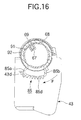
- Figs. 15 and 16 are a first cross-sectional view and a second cross-sectional view, respectively, illustrating a pertinent portion of the toner cartridge 41 when the toner cartridge 41 has been detached from the body 37.
- the pin 69 retracts to a second position or a retracted position into the recess 67 as shown in Figs. 15 and 16 , so that the knob 92 and the body 91 are unlocked from each other.
- the pin 69 has a length such that once the pin 69 has retracted into the recess 67, the pin 69 is completely in the recess the recess 67.
- the pin 69, recess 67, and recess 68 are related as follows: D ⁇ 1 ⁇ L ⁇ D ⁇ 2 where L is the length of the pin 69, D1 is the depth of the recess 68, and D2 is the depth of the recess 67.
- the operation lever 63 may be a component separate from the knob 82 or 92 and coupled by means of a coupling member.
- the embodiments have been described in terms of a printer, the invention may be applied to, for example, copying machines, facsimile machines, and multi-function peripherals (MFPs).
- MFPs multi-function peripherals
Landscapes
- Physics & Mathematics (AREA)
- General Physics & Mathematics (AREA)
- Dry Development In Electrophotography (AREA)
Abstract
Description
- The present invention relates to a powder developer, a developing apparatus, and an image forming apparatus.
- Conventional image forming apparatuses include printers, copying machines, and multi-function peripherals (MFPs). For example, a printer includes image forming units. The image forming unit includes a photoconductive drum, a charging roller, and a developing unit. The charging roller uniformly charges the surface of the photoconductive drum. An LED head illuminates the charged surface of the photoconductive drum in accordance with image data to form an electrostatic latent image on the photoconductive drum. A thin layer of toner is formed on the developing roller, and the toner on the developing roller is supplied to the electrostatic latent image to form a toner image on the photoconductive drum. The toner image is then transferred by a transfer roller onto a print medium or paper. The toner image on the print medium is then fixed into a permanent image.
-
JP 2003-50505A - The toner cartridge suffers from a problem in that the shutter may be opened with the toner discharging opening facing upward, before the toner cartridge has been attached to the image forming unit. If the shutter is opened inadvertently, foreign matter (e.g., paper particles) may enter the toner cartridge.
- An object of the invention is to solve the drawbacks of conventional image forming apparatuses.
- Another object of the invention is to provide a developer holding apparatus in which foreign matter is prevented from entering the developer holding apparatus.
- Still another object of the invention is to provide a developing unit that employs the developer holding apparatus and an image forming apparatus that employs the developing unit.
- A powder developer holding apparatus is capable of preventing powder developer from leaking. A housing (43) holds powder developer and includes a discharging opening (44) through which the powder developer is discharged. A shutter (42) is mounted to the housing (43) and is rotatable relative to the housing (43) to an opening position where the discharging opening (44) is opened or to a closing position where the discharging opening (44) is closed. A locking member (54, 69) is slidably mounted to said shutter (42), and prevents the shutter from rotating relative to the housing when the powder developer holding apparatus is oriented such that the discharging opening (44) faces upward in a gravitational direction.
- A developing apparatus incorporates the powder developer holding apparatus of the aforementioned configuration.
- An image forming apparatus incorporates the powder developer holding apparatus of the aforementioned configuration.
- Further scope of applicability of the present invention will become apparent from the detailed description given hereinafter. However, it should be understood that the detailed description and specific examples, while indicating preferred embodiments of the invention, are given by way of illustration only, since various changes and modifications within the scope of the invention will become apparent to those skilled in the art from this detailed description.
- The present invention will become more fully understood from the detailed description given hereinbelow and the accompanying drawings which are given by way of illustration only, and thus are not limiting the present invention, and wherein:
-
Fig. 1 illustrates the general configuration of a printer of a first embodiment; -
Fig. 2 is a cross-sectional view of an ID unit of the first embodiment; -
Fig. 3A is a perspective view of a toner cartridge of a first embodiment; -
Figs. 3B and 3C are perspective views of a shutter; -
Fig. 4 illustrates the toner cartridge when an operation lever is at a closing position; -
Fig. 5 illustrates the toner cartridge when the operation lever is at an opening position; -
Figs. 6 and 7 are a first cross-sectional view and a second cross-sectional view, respectively, illustrating a pertinent portion of the toner cartridge when the toner cartridge has been attached to the body of the ID unit; -
Figs. 8 and 9 are a first cross-sectional view and a second cross-sectional view, respectively, illustrating a pertinent portion of the toner cartridge when the toner cartridge is oriented such that the discharging opening faces upward; -
Fig. 10 is a perspective exploded view of a toner cartridge of a second embodiment; -
Fig. 11 is a perspective view illustrating the toner cartridge when an operation lever is at a closing position; -
Fig. 12 is a perspective view illustrating the toner cartridge when the operation lever is at an opening position; -
Figs. 13 and14 are a first cross-sectional view and a second cross-sectional view, respectively, illustrating a pertinent portion of the toner cartridge when the toner cartridge has been attached to a body of an ID unit; and -
Figs. 15 and16 are a first cross-sectional view and a second cross-sectional view, respectively, illustrating a pertinent portion of the toner cartridge when the toner cartridge has been detached from the body of the ID unit. - The present invention will be described in detail with reference to the accompanying drawings. An image forming apparatus of the invention will be described in terms of a printer.
-
Fig. 1 illustrates the general configuration of a printer of a first embodiment. - Referring to
Fig. 1 , a medium holder or apaper cassette 11 is disposed at a lower portion of the printer. Thepaper cassette 11 holds a stack of print media (e.g., print paper, not shown). A paper feeding mechanism is disposed adjacent to the front end of thepaper cassette 11, and includes afeed roller 12 and aseparator roller 13. The paper feeding mechanism feeds the print paper on a page-by-page basis in to a transport path. The print paper is fed to atransport roller 14 and then to atransport roller 15, so that the print paper advances through image forming units (referred to as ID unit hereinafter) 16BK, 16Y, 16M, and 16C that form black, yellow, magenta, and cyan toner images, respectively. - The ID units 16BK, 16Y, 16M, and 16C include image bearing bodies or photoconductive drums 31Bk, 31Y, 31M, and 31C, respectively. Disposed around the photoconductive drums 31Bk, 31Y, 31M, and 31C are exposing units or LED heads 22BK, 22Y, 22M, and 22C, respectively, which extend in parallel to the photoconductive drums 31BK, 31Y, 31M, and 31C. The exposing units may also be a laser type exposing unit.
- A transfer unit is disposed to face the ID units 16BK, 16Y, 16M, and 16C. The transfer unit includes a drive roller R1, a driven roller R2, a
transport belt 17 disposed about the drive roller R1 and driven roller R2, and transfer rollers 21BK, 21Y, 21M, and 21C. The drive roller R1 drives thetransport belt 17 to run. Thetransfer rollers transport belt 17 sandwiched between the photoconductive drums 31BK, 31Y, 31M, and 31C and the transfer rollers 21BK, 21Y, 21M, and 21C. - The
transport belt 17 runs in a direction shown by arrow Q to transport the print paper through the respective ID units 16BK, 16Y, 16M, and 16C so that the toner images of the respective colors are transferred onto the print paper in registration to form a full color toner image. - Subsequently, the print paper is advanced to a
fixing unit 36 where the full color toner image is fixed into a full color permanent image. Then, the print paper is further advanced by atransport roller 19 from thefixing unit 36, and then by adischarge roller 20 onto a stacker outside of the printer. - The ID units 16BK, 16Y, 16M, and 16C will be described. Each of the ID units 16BK, 16Y, 16M, and 16C may be substantially identical; for simplicity only the operation of the ID unit 16BK for forming black images will be described, it being understood that the other ID units 16BK, 16Y, 16M, and 16C may work in a similar fashion.
-
Fig. 2 is a cross-sectional view of the ID unit 16BK of the first embodiment. - Referring to
Fig. 2 , atoner cartridge 41 is detachably attached to abody 37 of the ID unit 16BK (powder developer holding apparatus). Thetoner cartridge 41 holds black powder developer or toner (not shown), which is supplied into thebody 37. Thetoner cartridge 41 includes a housing or acase 43 in which a dischargingopening 44 is formed. Ashutter 42 is attached into thecase 43 such that theshutter 42 is slidably movable along a substantially cylindrical inner wall of thecase 43 to open or close the dischargingopening 44 and is rotatable about its longitudinal axis. Theshutter 42 includes anopening 42a formed therein. When theshutter 42 is rotated such that theopening 42a and the dischargingopening 44 overlap one another, the toner is discharged from thetoner cartridge 41 into the developingunit 30. When theshutter 42 is rotated such that theopening 42a and the dischargingopening 44 do not overlap one another, the dischargingopening 44 is completely closed.Fig. 2 illustrates the shutter position when the shutter closes the dischargingopening 44. - The
body 37 includes a concavely cylindrical mounting surface for receiving thetoner cartridge 41 thereon. The mounting surface is formed with adeveloper receiving opening 45 therein. The toner discharged from thetoner cartridge 41 is received into thebody 37 through thedeveloper receiving opening 45. - The ID unit 16BK includes a photoconductive drum 31BK, a charging
roller 32, a developingroller 33, atoner supplying roller 34, a developingblade 35, and acleaning blade 36. The chargingroller 32 uniformly charges the surface of the photoconductive drum 31BK. Thetoner supplying roller 34 supplies the toner to the developingroller 33. The developingblade 35 forms a thin layer of toner on the developingroller 33. The developingroller 33 holds the thin layer of toner thereon. Thecleaning blade 36 removes the residual toner from the surface of the photoconductive drum 31BK. - A drive motor (not shown) drives the developing
roller 33 and thetoner supplying roller 34 in directions shown by arrows C and B, respectively, during printing, so that the toner is supplied from thetoner supplying roller 34 to the developingroller 33. As the developingroller 33 rotates, the developingblade 35 in pressure contact with the developingroller 36 forms the thin layer of toner on the developingroller 33, removing excess toner from the developingroller 33. As the developingroller 33 further rotates, the thin layer of toner is brought into contact with the photoconductive drum 31BK. - The photoconductive drum 31BK is driven by a drive motor (not shown) to rotate in a direction shown by arrow A. The surface of the photoconductive drum 31BK is uniformly charged by the charging
roller 32. The LED head 22BK illuminates the charged surface of the photoconductive drum 31BK to form an electrostatic latent image in accordance with print data. The electrostatic latent image is developed with the toner supplied from the thin layer of toner formed on the developingroller 33. - The configuration of the
toner cartridge 41 will be described.Fig. 3A is a perspective exploded view of thetoner cartridge 41 of the first embodiment.Figs. 3B and 3C are perspective views of the shutter.Fig. 4 illustrates thetoner cartridge 41 when anoperation lever 63 is at a closing position andFig. 5 illustrates thetoner cartridge 41 when theoperation lever 63 is at an opening position. - Referring to
Figs. 4 and 5 , thetoner cartridge 41 includes thecase 43 and theshutter 42 detachably attached to thecase 43. Thecase 43 includes a generally cylindrical lower bottom 43a in which thetoner discharging opening 44 is formed. Theshutter 42 is generally in the shape of a hollow cylinder. Theshutter 42 includes abody 81, aknob 92 that fits over one end portion of the body 81 (Fig. 3A ). Theknob 92 includes a shortcylindrical portion 82 that fits to thebody 81 such that theshutter 42 is rotatable together with theknob 92 relative to thebody 81. Theknob 92 includes theoperation lever 63 that extends radially from theknob 92. Theknob 92 also includes three radial projections (Figs. 6-9 ). Thebody 81 includes ashutter portion 42c that closes the dischargingopening 44 and anopening 42a that opens the dischargingopening 44. Thebody 81 also includes three recesses to which the three radial projections of theknob 92 fits so that theknob 92 and thebody 81 are unable to rotate relative to each other but are able to rotate together. Theshutter portion 42c andopening 42a extend in a direction parallel to a longitudinal direction of thebody 81. - A sealing
member 42d is formed of, for example, a sponge material, and is bonded to the outer circumferential surface adjacent to theopening 42a. The sealingmember 42d seals the gap between theshutter 42 and thecase 43 to prevent the toner from leaking from thecase 43. Theoperation lever 63 is in one piece with theshutter 42, and extends in a radial direction from theknob 92. Thecase 43 includes aside wall 43b from which aguide portion 43c projects outwardly. Theguide portion 43c guides theshutter 42 into thecase 43 when theshutter 42 is inserted into thecase 43. - If the
toner cartridge 41 is configured such that the shutter can be opened with the dischargingopening 44 facing upward before attaching thetoner cartridge 41 to thebody 37, inadvertently opening theshutter 42 may allow foreign matter such as paper particles to enter thetoner cartridge 41. In order to solve this drawback, thetoner cartridge 41 includes a rotation limiting mechanism that is disposed between thecase 43 and theshutter 42 and limits rotation of theshutter 42 relative to thetoner cartridge 41. The rotation limiting mechanism includes a stopper or aprojection 51 and a locking element or apin 54. Theprojection 51 projects from theside wall 43b in the vicinity of theguide portion 43c. Thepin 54, which will be described later, is disposed on theshutter 42. Theprojection 51 is substantially rectangular in the first embodiment, but may be in any shape. - The rotation limiting mechanism will be described in detail.
-
Figs. 6 and 7 are a first cross-sectional view and a second cross-sectional view, respectively, illustrating a pertinent portion of thetoner cartridge 41 when thetoner cartridge 41 has been attached to thebody 37.Figs. 8 and 9 are a first cross-sectional view and a second cross-sectional view, respectively, illustrating a pertinent portion of thetoner cartridge 41 when thetoner cartridge 41 has been detached from thebody 37. -
Figs. 6-9 illustrate the portions that project outwardly from theside wall 43b, and therefore do not illustrate the dischargingopening 44 andopening 42a.Figs. 6-9 illustrate cross-sectional views of a portion of theshutter 42 between theoperation lever 63 and theside wall 43b, and therefore do not show thelever 63. - Referring to
Figs. 6 and 7 , thecase 43 includes thebottom surface 43a that extends in a longitudinal direction of thetoner cartridge 41 and aguide portion 43c that projects from theside wall 43b. - The short
cylindrical portion 82 includes aradial extension 85.Projections knob 92 substantially in a radial direction. Anarcuate wall 85c extends across theprojections shutter 42. Referring toFig. 6 , theprojection 85a is formed at a position substantially in a gravitational direction, and theprojection 85b is formed at a position a predetermined angle away from theprojection 85a. Theprojections arcuate wall 85c cooperate to define a moveable range θ in which theshutter 42 may rotate. When the user operates theoperation lever 63, theshutter 42 rotates within the movable range θ. Thearcuate wall 85c includes astep 85d that serves as a first stopper. Theprojection 85b serves as a second stopper. - A stopper or a
projection 43d projects outwardly from theside wall 43b in a direction substantially parallel to the longitudinal axis of thetoner cartridge 41. A stopper orprojection 43e also projects from one end of thebottom surface 43a. When theshutter 42 is positioned at the closing position where theshutter 42 closes the dischargingopening 44, theprojection 85b engages theprojection 43e. When theshutter 42 is rotated in a direction shown by arrow D shown inFig. 7 to an opening position where theshutter 42 opens the dischargingopening 44, thestep 85d engages theprojection 43d. - A
recess 53 is formed in thebody 81 at a position to which thebody 81 is rotated from a position in a gravitational direction through 25 degrees approximately. Thepin 54 is received in therecess 53 such that thepin 54 is slidable due to gravity in therecess 53. Astopper surface 55 is formed at a position such that thestopper surface 55 faces therecess 53. - The
pin 54 has a length such that when thetoner cartridge 41 has been attached to thebody 37 of the ID unit 16BK and therefore the dischargingopening 44 faces downward, thepin 54 is completely received in therecess 53 and will not project outwardly from therecess 53. Thus, theshutter 42 is allowed to rotate between the opening position where the dischargingopening 44 is opened and the closing position where the dischargingopening 44 is closed. - When the
toner cartridge 41 has been detached from thebody 37 and the dischargingopening 44 faces upward, thepin 54 extends to a first position or an extended position from therecess 53 due to gravity, and abuts thestopper surface 55 as shown inFigs. 8 and 9 . - Thus, when the discharging
opening 44 faces upward, if the user operates the operation lever 63 (Fig. 1 ) in an attempt to cause theshutter 42 to rotate in a direction shown by arrow E (Fig. 9 ), thepin 54 abuts theprojection 51, not allowing theshutter 42 to rotate any further toward the opening position. This prevents the dischargingopening 44 from being opened. When thetoner cartridge 41 is attached to thebody 37, thepin 54 moves out of engagement with theprojection 51 allowing theshutter 42 to open or close the dischargingopening 44. - As described above, the
projection 51 projects from theside wall 43b in a direction parallel to a direction in which thecase 43 extends, being disposed in the vicinity of theguide portion 43c of thecase 43. Thepin 54 is slidably received in therecess 53 formed in thebody 81 of theshutter 42. Thus, when thetoner cartridge 41 has been attached to thebody 37 of the ID unit 16BK, thepin 54 retracts into therecess 53 so that thepin 54 will move to a second position or retracted position where thepin 54 is out of engagement with thepin 51 to allow theshutter 42 rotate to the opening position. When thetoner cartridge 41 has been detached from thebody 37 of the ID unit, and is held with the dischargingopening 44 facing upward, thepin 54 extends from therecess 53, so that thepin 54 will move into engagement with thepin 51 to prevent theshutter 42 from rotating to the opening position. - This prevents the
shutter 42 from being opened inadvertently so that no foreign matter enters thetoner cartridge 41. - While the
projection 51 is disposed in the vicinity of an upper portion of theguide portion 43c in the gravitational direction, the projection may be disposed any position as long as the dischargingopening 44 will not open when thepin 54 abuts theprojection 51. - Elements similar to those of the first embodiment have been given the same reference member.
-
Fig. 10 is a perspective exploded view of atoner cartridge 41 of a second embodiment.Fig. 11 illustrates thetoner cartridge 41 when anoperation lever 63 is at a closing position where ashutter 42 closes a dischargingopening 44 of atoner cartridge 41, andFig. 12 illustrates thetoner cartridge 41 when theoperation lever 63 is at an opening position where theshutter 42 opens the dischargingopening 44 of thetoner cartridge 41. - An
arcuate groove 65 is formed in thebottom surface 43a of thecase 43 in the vicinity of one longitudinal end of thecase 43. Aprojection 92a is slidable only in thegroove 65 so that theknob 92 is prevented from being pulled out of engagement with a first portion or abody 91 of theshutter 42. Theprojection 92a is formed on an outer surface of a second portion or aknob 92, being received in thearcuate groove 65 from inside of thecase 43. Thegroove 65 may also serve as a means for defining an extent in which theknob 92 is rotatable relative to thebody 91, and ends 65a and 65b of thegroove 65 serve as stoppers, respectively, that limit the extent in which theshutter 42 is moved when theoperation lever 63 is operated. - The
toner cartridge 41 includes acase 43 having abottom surface 43a in the shape of a partial cylinder. A dischargingopening 44 is formed in thebottom surface 43a. Theshutter 42 is generally in the shape of a hollow cylinder, and mounted to thebottom surface 43a. Theshutter 42 is movable to the opening position where theshutter 42 opens the discharging theopening 44, and to the closing position where theshutter 42 closes the dischargingopening 44. Theshutter 42 includes a shutter portion and anopening 42a. - The
shutter 42 includes a first portion or abody 91 that extends over the entire length of thecase 43, and a second portion orknob 92 that detachably slidably fits over a slidingsurface 91a formed at one longitudinal end portion of theshutter 42. Theknob 92 is selectively locked to theshutter 42 by means of locking member or apin 69, which will be described later, when thepin 69 moves relative to the shutter and theknob 92. - The
body 91 includes the slidingsurface 91a over which theknob 92 fits, ashutter portion 42c that closes the dischargingopening 44, and anopening 42a that opens the dischargingopening 44. Anoperation lever 63 is in one piece with theknob 92, and extends radially outwardly from theknob 92. - Thus, when the
operation lever 63 is operated after theknob 92 has fitted over thebody 91, theshutter 42 rotates to open or close the dischargingopening 44. -
Figs. 13 and14 are a first cross-sectional view and a second cross-sectional view, respectively, illustrating a pertinent portion of thetoner cartridge 41 when thetoner cartridge 41 has been attached to abody 37 of an ID unit 16BK. -
Fig. 13 illustrates aradial extension 85 when it is at the closing position. When theradial extension 85 is at the closing position, aprojection 85b abuts a stopper or aprojection 43e.Fig. 14 illustrates theradial extension 85 when it is at the opening position. When the radial extension is at the closing position, aprojection 85a abuts a stopper or aprojection 43d. - The short
cylindrical portion 92 includes theradial extension 85. Theradial extension 85 includes theprojections cylindrical portion 92 in a substantially radial direction. Anarcuate wall 85c extends across theprojections Fig. 13 ) with respect to the rotational axis of theshutter 42. Theradial extension 85 defines angular range in which theshutter 42 may rotate. When the user operates theoperation lever 63, theshutter 42 rotates within the angular range. - The
projection 43d projects outwardly from theside wall 43b in a direction substantially parallel to the longitudinal axis of thetoner cartridge 41. Aprojection 43e also projects from one end of thebottom surface 43a. Theprojections shutter 42 is positioned at the closing position, theprojection 85b engages theprojection 43e. When theshutter 42 is rotated in a direction shown by arrow D shown inFig. 7 to a position where theshutter 42 opens the dischargingopening 44, thestep 85d engages theprojection 43d. - A
recess 67 extends a predetermined length in a radial direction inside of thebody 91. A locking element or thepin 69 is received in therecess 67 such that thepin 69 is slidable due to gravity in therecess 67. Astopper surface 55 is formed at a position where thestopper surface 55 faces therecess 67 when theshutter 42 closes the dischargingopening 44 of thetoner cartridge 41. Theknob 92 includes a stopper or arecess 68 formed in an inner surface of theknob 92, and is configured to receive a part of thepin 69 therein. - The
recess 68 is formed at a position such that when thelever 63 is at the closing position and thebody 91 is at a rotational position where the shutter closes the dischargingopening 44, therecess 68 is in alignment with therecess 67. - When the
toner cartridge 41 is mounted to thebody 37 such that the dischargingopening 44 faces downward, thepin 69 extends to a first position or an extended position from therecess 67 as shown inFigs. 13 and14 due to gravity to enter therecess 68, so that theknob 92 and thebody 91 are locked to each other by means of thepin 69. The locking engagement of theknob 92 and thebody 91 allows theshutter 42 to move either to the opening position where the dischargingopening 44 is opened or to the closing position where the dischargingopening 44 is closed. -
Figs. 15 and16 are a first cross-sectional view and a second cross-sectional view, respectively, illustrating a pertinent portion of thetoner cartridge 41 when thetoner cartridge 41 has been detached from thebody 37. - Referring to
Figs. 15 and16 , when thetoner cartridge 41 is oriented such that the dischargingopening 44 faces upward after thetoner cartridge 41 has been detached from thebody 37, thepin 69 retracts to a second position or a retracted position into therecess 67 as shown inFigs. 15 and16 , so that theknob 92 and thebody 91 are unlocked from each other. Thepin 69 has a length such that once thepin 69 has retracted into therecess 67, thepin 69 is completely in the recess therecess 67. - The
pin 69,recess 67, andrecess 68 are related as follows:
pin 69, D1 is the depth of therecess 68, and D2 is the depth of therecess 67. - As described above, when the
toner cartridge 41 is oriented such that the dischargingopening 44 faces upward, thepin 69 is out of engagement with therecess 68. Thus, if the user operates theoperation lever 63 to rotate theshutter 42 in a direction of arrow F from theFig. 15 position to theFig. 16 position, only theknob 92 is allowed to rotate and thebody 91 is not allowed to rotate. This prevents theshutter 42 from rotating so that the dischargingopening 44 remains closed. - While the first and second embodiments have been described in term of the
operation lever 63 formed in one piece with theknob operation lever 63 may be a component separate from theknob - Although the embodiments have been described in terms of a printer, the invention may be applied to, for example, copying machines, facsimile machines, and multi-function peripherals (MFPs).
- The invention being thus described, it will be obvious that the same may be varied in many ways. Such variations are not to be regarded as a departure from the scope of the invention, and all such modifications as would be obvious to one skilled in the art intended to be included within the scope of the following claims.
Claims (10)
- A powder developer holding apparatus comprising:a housing (43) that holds powder developer, said housing including a discharging opening (44) through which the powder developer is discharged;a shutter (42) mounted to said housing (43), said shutter (42) being rotatable relative to said housing (43) to an opening position where the discharging opening (44) is opened or to a closing position where the discharging opening (44) is closed;a locking member (54, 69) slidably mounted to said shutter (42), wherein when the powder developer holding apparatus is oriented such that the discharging opening (44) faces upward in a gravitational direction, said locking member (54, 69) slides relative to said shutter (42) to a position where said locking member prevents said shutter from rotating relative to said chamber.
- The powder developer holding apparatus according to claim 1, wherein said housing includes a stopper (51) formed thereon,
wherein when the powder developer holding apparatus is oriented such that the discharging opening (44) faces upward, said locking member (54) slides relative to said housing to the position where when said shutter (42) is rotated relative to said housing (43), said locking member (54) engages the stopper (51) preventing said shutter (42) from rotating to the opening position. - The powder developer holding apparatus according to claim 2, wherein the position is a first position,
wherein when the powder developer holding apparatus is oriented such that the discharging opening (44) faces downward, said locking member (54) slides relative to said shutter (42) to a second position where when said shutter (42) is rotated relative to said housing (43), said locking member (54) remains in said shutter (42) so that the stopper (51) allows said shutter (42) to rotate to the opening position. - The powder developer holding apparatus according to any of the preceding claims, wherein the position is a first position and said housing includes a stopper (51) formed thereon,
wherein when the powder developer holding apparatus is oriented such that the discharging opening (44) faces downward, said locking member (54) slides relative to said shutter (42) to a second position where when said shutter (42) is rotated relative to said housing (43), said locking member (54) remains in said shutter (42) so that the stopper (51) allows said shutter (42) to rotate to the opening position. - The powder developer holding apparatus according to any of the preceding claims, wherein said shutter (42) includes a first portion (91), a second portion (92) that slidably fits over the first portion (91), and a stopper (68) formed in said shutter;
wherein when the powder developer holding apparatus is oriented such that the discharging opening (44) faces upward, said locking member (69) slides relative to said housing to the position where when the second portion (92) is rotated relative to said housing (43), said locking member (69) remains in said shutter (42) so that the stopper (68) prevents said shutter (42) from rotating to the opening position. - The powder developer holding apparatus according to Claim 5, wherein the position is a first position and said shutter (42) includes a first portion (91), a second portion (92) that slidably fits over the first portion (91), and a stopper (68) formed in said shutter;
wherein when the powder developer holding apparatus is oriented such that the discharging opening (44) faces downward, said locking member (69) slides relative to said shutter (42) to a second position where when the second portion (92) is rotated relative to said housing (43), said locking member (69) engages the stopper (68) allowing said shutter (42) to rotate to the opening position. - The powder developer holding apparatus according to any of the preceding claims, wherein the position is a first position and said shutter (42) includes a first portion (91), a second portion (92) that slidably fits over the first portion (91), and a stopper (68) formed in said shutter;
wherein when the powder developer holding apparatus is oriented such that the discharging opening (44) faces downward, said locking member (69) slides relative to said shutter (42) to a second position where when the second portion (92) is rotated relative to said housing (43), said locking member (69) engages the stopper (68) allowing said shutter (42) to rotate to the opening position. - The powder developer holding apparatus according to any of the preceding claims, wherein said shutter (42) includes an operation lever (63);
wherein when the operation lever (63) is operated by an operator, said shutter (42) is caused to rotate to either the opening position or to the closing position. - A developing apparatus incorporating the powder developer holding apparatus according to any one of Claim 1 to Claim 4.
- The powder developer holding apparatus according to any of claims 1 to 8 incorporated in an image forming apparatus.
Applications Claiming Priority (1)
| Application Number | Priority Date | Filing Date | Title |
|---|---|---|---|
| JP2008072044A JP4612073B2 (en) | 2008-03-19 | 2008-03-19 | Powder container, developing device, and image forming apparatus |
Publications (3)
| Publication Number | Publication Date |
|---|---|
| EP2110713A2 true EP2110713A2 (en) | 2009-10-21 |
| EP2110713A3 EP2110713A3 (en) | 2010-08-11 |
| EP2110713B1 EP2110713B1 (en) | 2017-03-22 |
Family
ID=41040508
Family Applications (1)
| Application Number | Title | Priority Date | Filing Date |
|---|---|---|---|
| EP09153426.3A Active EP2110713B1 (en) | 2008-03-19 | 2009-02-23 | Powder developer holding apparatus, developing apparatus, and image forming apparatus |
Country Status (4)
| Country | Link |
|---|---|
| US (1) | US8050591B2 (en) |
| EP (1) | EP2110713B1 (en) |
| JP (1) | JP4612073B2 (en) |
| CN (1) | CN101539744B (en) |
Cited By (2)
| Publication number | Priority date | Publication date | Assignee | Title |
|---|---|---|---|---|
| CN103376708A (en) * | 2012-04-27 | 2013-10-30 | 利盟国际有限公司 | Shutter assembly for a toner container |
| US9176423B2 (en) | 2013-01-21 | 2015-11-03 | Oki Data Corporation | Developer container, development device, and image formation apparatus that have shutter movement restriction member to restrict movement of shutter member |
Families Citing this family (8)
| Publication number | Priority date | Publication date | Assignee | Title |
|---|---|---|---|---|
| JP4689422B2 (en) * | 2005-09-27 | 2011-05-25 | 株式会社沖データ | Developer cartridge, image forming unit, and image forming apparatus |
| JP4598089B2 (en) * | 2008-01-24 | 2010-12-15 | 株式会社沖データ | Developer container and image forming apparatus |
| JP5591003B2 (en) * | 2010-07-22 | 2014-09-17 | 株式会社沖データ | Developer container, developing device, and image forming apparatus |
| JP5659717B2 (en) * | 2010-11-10 | 2015-01-28 | 富士ゼロックス株式会社 | Developer container and image forming apparatus |
| JP5858939B2 (en) * | 2013-01-28 | 2016-02-10 | 株式会社沖データ | Developer container, development forming unit, and image forming apparatus |
| JP6288962B2 (en) * | 2013-06-25 | 2018-03-07 | キヤノン株式会社 | Shutter mechanism, developer container, process cartridge, image forming apparatus |
| CN108284042A (en) * | 2018-04-13 | 2018-07-17 | 遵义市兴英鹏塑料包装有限公司 | Brush coating roller bearing for producing ox-hide bag |
| JP7047674B2 (en) * | 2018-08-30 | 2022-04-05 | 沖電気工業株式会社 | Developer container, image forming unit and image forming apparatus |
Citations (1)
| Publication number | Priority date | Publication date | Assignee | Title |
|---|---|---|---|---|
| JP2003050505A (en) | 2001-08-07 | 2003-02-21 | Oki Data Corp | Toner cartridge and image forming device |
Family Cites Families (5)
| Publication number | Priority date | Publication date | Assignee | Title |
|---|---|---|---|---|
| JP4693393B2 (en) * | 2003-11-19 | 2011-06-01 | キヤノン株式会社 | Developer supply device |
| JP2006235592A (en) * | 2005-01-31 | 2006-09-07 | Kyocera Mita Corp | Toner cartridge |
| JP4134061B2 (en) * | 2005-02-14 | 2008-08-13 | シャープ株式会社 | Toner cartridge and image forming apparatus to which the toner cartridge is mounted |
| US7245860B2 (en) * | 2005-03-25 | 2007-07-17 | General Plastic Industrial Co., Ltd. | Toner cartridge |
| JP4388057B2 (en) * | 2006-08-31 | 2009-12-24 | 株式会社沖データ | Developer container, image forming unit, and image forming apparatus |
-
2008
- 2008-03-19 JP JP2008072044A patent/JP4612073B2/en active Active
-
2009
- 2009-02-23 EP EP09153426.3A patent/EP2110713B1/en active Active
- 2009-02-26 CN CN200910008132.8A patent/CN101539744B/en active Active
- 2009-02-27 US US12/379,736 patent/US8050591B2/en not_active Expired - Fee Related
Patent Citations (1)
| Publication number | Priority date | Publication date | Assignee | Title |
|---|---|---|---|---|
| JP2003050505A (en) | 2001-08-07 | 2003-02-21 | Oki Data Corp | Toner cartridge and image forming device |
Cited By (4)
| Publication number | Priority date | Publication date | Assignee | Title |
|---|---|---|---|---|
| CN103376708A (en) * | 2012-04-27 | 2013-10-30 | 利盟国际有限公司 | Shutter assembly for a toner container |
| EP2657789A3 (en) * | 2012-04-27 | 2017-01-11 | Lexmark International, Inc. | Shutter assembly for a toner container |
| CN103376708B (en) * | 2012-04-27 | 2019-03-26 | 利盟国际有限公司 | Opening and closing device assembly for toner container |
| US9176423B2 (en) | 2013-01-21 | 2015-11-03 | Oki Data Corporation | Developer container, development device, and image formation apparatus that have shutter movement restriction member to restrict movement of shutter member |
Also Published As
| Publication number | Publication date |
|---|---|
| EP2110713B1 (en) | 2017-03-22 |
| EP2110713A3 (en) | 2010-08-11 |
| CN101539744B (en) | 2014-12-24 |
| CN101539744A (en) | 2009-09-23 |
| JP4612073B2 (en) | 2011-01-12 |
| US20090238609A1 (en) | 2009-09-24 |
| US8050591B2 (en) | 2011-11-01 |
| JP2009229561A (en) | 2009-10-08 |
Similar Documents
| Publication | Publication Date | Title |
|---|---|---|
| EP2110713B1 (en) | Powder developer holding apparatus, developing apparatus, and image forming apparatus | |
| EP1927898B1 (en) | Powder material cartridge, image forming section, image forming apparatus | |
| KR100747728B1 (en) | Developer container, developer supplying device, and image forming apparatus | |
| JP4673643B2 (en) | Developing device, developer cartridge, and image forming apparatus | |
| US8787803B2 (en) | Developing device, image forming unit and image forming apparatus | |
| EP1895368B1 (en) | Developer material container, image forming unit, and image forming apparatus | |
| JP4543077B2 (en) | Toner cartridge and image forming apparatus | |
| US9268259B2 (en) | Developer material holding apparatus, supporting apparatus that supports the developer material holding apparatus, and image forming apparatus | |
| EP2317397A2 (en) | Developing device, developing cartridge, process cartridge and image forming apparatus | |
| US8260169B2 (en) | Developer storing container, developing unit, developing device and image forming apparatus capable of reducing the developer from being scattered | |
| US7389067B2 (en) | Developer cartridge of an image forming apparatus for removably mounting | |
| JP4343622B2 (en) | Developer supply container | |
| EP1959313B1 (en) | Developer container and image forming apparatus that incorporates the developer container | |
| CN106200312B (en) | Storage container and image forming apparatus | |
| KR100846834B1 (en) | Toner cartridge | |
| JP6765245B2 (en) | Image forming device | |
| US11669042B2 (en) | Image forming device and process cartridge therefor | |
| JP2017146512A (en) | Developer container, image forming unit, and image forming apparatus | |
| JP5771552B2 (en) | Developer container, developing device, and image forming apparatus |
Legal Events
| Date | Code | Title | Description |
|---|---|---|---|
| PUAI | Public reference made under article 153(3) epc to a published international application that has entered the european phase |
Free format text: ORIGINAL CODE: 0009012 |
|
| AK | Designated contracting states |
Kind code of ref document: A2 Designated state(s): AT BE BG CH CY CZ DE DK EE ES FI FR GB GR HR HU IE IS IT LI LT LU LV MC MK MT NL NO PL PT RO SE SI SK TR |
|
| AX | Request for extension of the european patent |
Extension state: AL BA RS |
|
| PUAL | Search report despatched |
Free format text: ORIGINAL CODE: 0009013 |
|
| AK | Designated contracting states |
Kind code of ref document: A3 Designated state(s): AT BE BG CH CY CZ DE DK EE ES FI FR GB GR HR HU IE IS IT LI LT LU LV MC MK MT NL NO PL PT RO SE SI SK TR |
|
| AX | Request for extension of the european patent |
Extension state: AL BA RS |
|
| 17P | Request for examination filed |
Effective date: 20110211 |
|
| AKX | Designation fees paid |
Designated state(s): DE FR GB NL |
|
| 17Q | First examination report despatched |
Effective date: 20140121 |
|
| GRAP | Despatch of communication of intention to grant a patent |
Free format text: ORIGINAL CODE: EPIDOSNIGR1 |
|
| INTG | Intention to grant announced |
Effective date: 20161027 |
|
| GRAS | Grant fee paid |
Free format text: ORIGINAL CODE: EPIDOSNIGR3 |
|
| GRAA | (expected) grant |
Free format text: ORIGINAL CODE: 0009210 |
|
| AK | Designated contracting states |
Kind code of ref document: B1 Designated state(s): DE FR GB NL |
|
| REG | Reference to a national code |
Ref country code: GB Ref legal event code: FG4D |
|
| REG | Reference to a national code |
Ref country code: NL Ref legal event code: FP |
|
| REG | Reference to a national code |
Ref country code: DE Ref legal event code: R096 Ref document number: 602009044884 Country of ref document: DE |
|
| REG | Reference to a national code |
Ref country code: DE Ref legal event code: R097 Ref document number: 602009044884 Country of ref document: DE |
|
| REG | Reference to a national code |
Ref country code: FR Ref legal event code: PLFP Year of fee payment: 10 |
|
| PLBE | No opposition filed within time limit |
Free format text: ORIGINAL CODE: 0009261 |
|
| STAA | Information on the status of an ep patent application or granted ep patent |
Free format text: STATUS: NO OPPOSITION FILED WITHIN TIME LIMIT |
|
| 26N | No opposition filed |
Effective date: 20180102 |
|
| REG | Reference to a national code |
Ref country code: DE Ref legal event code: R081 Ref document number: 602009044884 Country of ref document: DE Owner name: OKI ELECTRIC INDUSTRY CO., LTD., JP Free format text: FORMER OWNER: OKI DATA CORPORATION, TOKYO, JP |
|
| REG | Reference to a national code |
Ref country code: GB Ref legal event code: 732E Free format text: REGISTERED BETWEEN 20220317 AND 20220323 |
|
| REG | Reference to a national code |
Ref country code: NL Ref legal event code: PD Owner name: OKI ELECTRIC INDUSTRY CO., LTD.; JP Free format text: DETAILS ASSIGNMENT: CHANGE OF OWNER(S), MERGE; FORMER OWNER NAME: OKI DATA CORPORATION Effective date: 20220308 |
|
| PGFP | Annual fee paid to national office [announced via postgrant information from national office to epo] |
Ref country code: FR Payment date: 20230110 Year of fee payment: 15 |
|
| PGFP | Annual fee paid to national office [announced via postgrant information from national office to epo] |
Ref country code: NL Payment date: 20240108 Year of fee payment: 16 |
|
| PGFP | Annual fee paid to national office [announced via postgrant information from national office to epo] |
Ref country code: DE Payment date: 20231228 Year of fee payment: 16 Ref country code: GB Payment date: 20240109 Year of fee payment: 16 |