EP2110457A2 - Platinum-modified cathodic arc coating - Google Patents
Platinum-modified cathodic arc coating Download PDFInfo
- Publication number
- EP2110457A2 EP2110457A2 EP09251023A EP09251023A EP2110457A2 EP 2110457 A2 EP2110457 A2 EP 2110457A2 EP 09251023 A EP09251023 A EP 09251023A EP 09251023 A EP09251023 A EP 09251023A EP 2110457 A2 EP2110457 A2 EP 2110457A2
- Authority
- EP
- European Patent Office
- Prior art keywords
- platinum
- ingot
- process according
- cathode
- coating
- Prior art date
- Legal status (The legal status is an assumption and is not a legal conclusion. Google has not performed a legal analysis and makes no representation as to the accuracy of the status listed.)
- Granted
Links
Images
Classifications
-
- C—CHEMISTRY; METALLURGY
- C23—COATING METALLIC MATERIAL; COATING MATERIAL WITH METALLIC MATERIAL; CHEMICAL SURFACE TREATMENT; DIFFUSION TREATMENT OF METALLIC MATERIAL; COATING BY VACUUM EVAPORATION, BY SPUTTERING, BY ION IMPLANTATION OR BY CHEMICAL VAPOUR DEPOSITION, IN GENERAL; INHIBITING CORROSION OF METALLIC MATERIAL OR INCRUSTATION IN GENERAL
- C23C—COATING METALLIC MATERIAL; COATING MATERIAL WITH METALLIC MATERIAL; SURFACE TREATMENT OF METALLIC MATERIAL BY DIFFUSION INTO THE SURFACE, BY CHEMICAL CONVERSION OR SUBSTITUTION; COATING BY VACUUM EVAPORATION, BY SPUTTERING, BY ION IMPLANTATION OR BY CHEMICAL VAPOUR DEPOSITION, IN GENERAL
- C23C14/00—Coating by vacuum evaporation, by sputtering or by ion implantation of the coating forming material
- C23C14/06—Coating by vacuum evaporation, by sputtering or by ion implantation of the coating forming material characterised by the coating material
- C23C14/14—Metallic material, boron or silicon
- C23C14/16—Metallic material, boron or silicon on metallic substrates or on substrates of boron or silicon
-
- C—CHEMISTRY; METALLURGY
- C23—COATING METALLIC MATERIAL; COATING MATERIAL WITH METALLIC MATERIAL; CHEMICAL SURFACE TREATMENT; DIFFUSION TREATMENT OF METALLIC MATERIAL; COATING BY VACUUM EVAPORATION, BY SPUTTERING, BY ION IMPLANTATION OR BY CHEMICAL VAPOUR DEPOSITION, IN GENERAL; INHIBITING CORROSION OF METALLIC MATERIAL OR INCRUSTATION IN GENERAL
- C23C—COATING METALLIC MATERIAL; COATING MATERIAL WITH METALLIC MATERIAL; SURFACE TREATMENT OF METALLIC MATERIAL BY DIFFUSION INTO THE SURFACE, BY CHEMICAL CONVERSION OR SUBSTITUTION; COATING BY VACUUM EVAPORATION, BY SPUTTERING, BY ION IMPLANTATION OR BY CHEMICAL VAPOUR DEPOSITION, IN GENERAL
- C23C14/00—Coating by vacuum evaporation, by sputtering or by ion implantation of the coating forming material
- C23C14/22—Coating by vacuum evaporation, by sputtering or by ion implantation of the coating forming material characterised by the process of coating
- C23C14/24—Vacuum evaporation
- C23C14/32—Vacuum evaporation by explosion; by evaporation and subsequent ionisation of the vapours, e.g. ion-plating
- C23C14/325—Electric arc evaporation
-
- C—CHEMISTRY; METALLURGY
- C23—COATING METALLIC MATERIAL; COATING MATERIAL WITH METALLIC MATERIAL; CHEMICAL SURFACE TREATMENT; DIFFUSION TREATMENT OF METALLIC MATERIAL; COATING BY VACUUM EVAPORATION, BY SPUTTERING, BY ION IMPLANTATION OR BY CHEMICAL VAPOUR DEPOSITION, IN GENERAL; INHIBITING CORROSION OF METALLIC MATERIAL OR INCRUSTATION IN GENERAL
- C23C—COATING METALLIC MATERIAL; COATING MATERIAL WITH METALLIC MATERIAL; SURFACE TREATMENT OF METALLIC MATERIAL BY DIFFUSION INTO THE SURFACE, BY CHEMICAL CONVERSION OR SUBSTITUTION; COATING BY VACUUM EVAPORATION, BY SPUTTERING, BY ION IMPLANTATION OR BY CHEMICAL VAPOUR DEPOSITION, IN GENERAL
- C23C14/00—Coating by vacuum evaporation, by sputtering or by ion implantation of the coating forming material
- C23C14/22—Coating by vacuum evaporation, by sputtering or by ion implantation of the coating forming material characterised by the process of coating
- C23C14/34—Sputtering
- C23C14/3407—Cathode assembly for sputtering apparatus, e.g. Target
Definitions
- the present disclosure relates to a process and an apparatus for forming a platinum modified cathodic arc coating on a part, such as a turbine engine component.
- the present disclosure is directed to a process for coating a part.
- the process broadly comprises the steps of: providing a chamber which is electrically connected as an anode; placing the part to be coated in the chamber; providing a cathode formed from a coating material to be deposited and platinum; and applying a current to the anode and the cathode to deposit the coating material and the platinum on the part.
- the present disclosure is also directed to an apparatus for depositing a platinum modified coating on a part.
- the apparatus broadly comprises a chamber which is electrically connected as an anode and in which the part to be coated is placed, and a cathode formed from a material to be deposited onto the part and platinum.
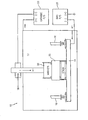
- the FIGURE is a schematic representation of a cathodic arc coating apparatus.
- the present disclosure relates to a process and apparatus for forming a platinum modified bond coat, such as a platinum-modified cathodic arc-deposited NiCoCrAlY bond coating.
- a platinum modified bond coat such as a platinum-modified cathodic arc-deposited NiCoCrAlY bond coating.
- the total coating composition of Pt-NiCoCrAlY is deposited by cathodic arc technology.
- the process by which the platinum is incorporated into the bond coat may be done in either of two ways: (1) the coating cathode material from which the coating is produced and deposited on the parts may be cast with the required amount of platinum in the ingot alloy; or (2) a coating cathode may be modified by platinum-plating the outside of an ingot and diffusing the platinum into the ingot alloy via heat treatment.
- the rate of depletion of aluminum from the bond coat is reduced, thus, increasing the life of the bond coat in the engine environment. Additionally, the platinum at the bond coat-superalloy interface lowers the activity of the aluminum in the bond coat and likely helps prevent the formation of SRZ. Because platinum is known to be a relatively slow diffuser among superalloy-containing elements, the introduction of platinum into the superalloy-bond coat interface may act to slow interdiffusion of elements from the superalloy into the bond coat. This helps in two primary ways by preventing elements which are detrimental to the formation of a continuous oxidation barrier in the bond coat from reaching the bond coat-TGO interface. Additionally, it slows the diffusion of nickel from the bond coat-superalloy interface which may in turn leave behind refractory-rich cellular by products often observed during SRZ formation.
- the Figure illustrates a coating apparatus for performing cathodic arc coating.
- the coating apparatus 10 has a chamber 12 which forms the anode. Within the chamber 12, there is a platter 14 on which one or more parts 16 to be coated, such as turbine engine components, are positioned.
- a stinger 18 extends into the chamber 12. The stinger 18 has attached to it a plurality of magnets 20 and a cathode 22.
- the coating apparatus 10 may be run at 300 - 500 amps with a current being applied to the cathode 22 and to the chamber (anode) 12 from a power source 23 and with a bias being applied to the parts 16 of -10V to - 100V using a power source 25.
- the power sources 23 and 25 may be any suitable power source(s) known in the art.
- the chamber 10 there may be a pressure of 10 - 100 microns (0.1 to 1.0 Pa) of a carrier gas such as argon.
- a carrier gas such as argon.
- the parts 16 may reach a temperature in the range of 400 to 600 degrees Fahrenheit (204-316°C).
- Coating time is variable and depends on the thickness of the desired coating.
- the cathode 22 may be formed from an ingot of the coating material to be deposited which either has platinum plated on it or platinum incorporated into it.
- the platinum may comprise from 1 to 100% of the material to be deposited onto the part(s) 16.
- a useful range for the platinum is from 4.0 to 60% by weight.
- the coating ingot forming the cathode 22 may be cast containing platinum in the aforesaid amount.
- the cast coating ingot forming the cathode 22 may be a platinum modified NiCoCrAlY material.
- the ingot may be cast so as to uniformly contain the platinum.
- the coating ingot may be cast without the platinum if desired.
- the coating ingots may be cast by vacuum induction melting (VIM).
- VIM vacuum induction melting
- the ingots may be cast at approximately 2750 to 3250 degrees Fahrenheit (1510-1788°C) (superheated above alloy melting temperature) in a partial pressure of argon gas.
- the ingots may then be hot-isostatic pressed at approximately 2100 to 2300 degrees Fahrenheit (1149-1260°C).
- the cast coating ingot without platinum may have its external surfaces plated with platinum. Where the platinum is plated onto the external surfaces of the ingot, it may be diffused inwardly.
- a unique functionality of the coating is that the platinum concentration may be graded from “high” to "low” or “zero” as the coating builds up from the substrate to the surface of the coating. In this way, platinum concentration would be greatest closes to the alloy and leanest at the coating surface with the environment or optionally deposited thermal barrier coating. Having platinum concentrated at the substrate-bond coat interface is beneficial in that it is a slowly diffusing species compared to other superalloy containing elements. Thus, the formation of deleterious phases such as secondary reaction zones (SRZ) may be slowed by the presence of platinum at this location.
- SRZ secondary reaction zones
- the coating material ingot to be plated may be prepared via grit blasting, such as 240 grit at 20-60 psi (138-414 MPa) for three to five minutes, and rinsed clean using acetone.
- the ingot may be electrically cleaned using an alkali solution for 3 minutes at 125 degrees Fahrenheit (52°C) at about 0.25 amps in a stainless steel beaker.
- Platinum may be plated to a desired thickness via a suitable electrolytic plating process. The thickness may be calculated based on the surface area to be coated.
- the ingot may be immersed in a platinum plating solution containing from 17 to 40 grams/litre platinum concentration (nominal concentration being approximately 30 grams/litre).
- Amperage is variable depending on ingot size, but may be in the range of from 0.2 to 0.6 amps.
- the platinum containing solution may be maintained at a temperature of about 190 to 200 degrees Fahrenheit (88-93°C).
- a low temperature heat treatment such as approximately 350 to 400 degrees Fahrenheit (177-205°C) for 2.5 to 4.0 hours, immediately follows the plating to out-gas any byproduct gasses from the plating process.
- An additional heat treatment may be performed at a high temperature, such as approximately 1900 to 2000 degrees Fahrenheit (1038-1093°C) for 3.5 to 5.0 hours, to diffuse the platinum into the coated material in order to allow the platinum to infiltrate the substrate material in the region of interest where the arc will run in the cathodic arc process.
- Cathodic arc coatings generally form dense, adherent coatings with uniform compositions from homogeneous composition cathode materials. For example, if the platinum is uniformly distributed in the cathode materials, the coating will contain a uniform compositional distribution of platinum.
- the process described herein may be used to fabricate bond coatings for thermal barrier coating systems. These bond coats may be used to provide oxidation protection for the underlying substrate material.
- the ingot has been described as being formed from a NiCoCrAlY material, it should be recognized that the ingot may be formed from other materials, such as a MCrAlY material where M is selected from the group consisting typically of nickel, iron, or cobalt.
Landscapes
- Chemical & Material Sciences (AREA)
- Chemical Kinetics & Catalysis (AREA)
- Engineering & Computer Science (AREA)
- Materials Engineering (AREA)
- Mechanical Engineering (AREA)
- Metallurgy (AREA)
- Organic Chemistry (AREA)
- Physical Vapour Deposition (AREA)
- Electrodes For Compound Or Non-Metal Manufacture (AREA)
- Coating By Spraying Or Casting (AREA)
- Solid-Phase Diffusion Into Metallic Material Surfaces (AREA)
Abstract
Description
- The present disclosure relates to a process and an apparatus for forming a platinum modified cathodic arc coating on a part, such as a turbine engine component.
- The high temperature exposure of nickel-based superalloys in turbine engines continues to increase. Thus, alloys must continually be adapted to this high temperature combustion environment. Advanced thermal barrier coating systems (TBCs) provide a means to shelter the structural element, i.e turbine blade or vane, from the highest temperatures in the engine; however, oxidation of the metal surface below still takes place as the thermal barrier coating is oxygen transparent. Metallic bond coats are added to the metallic surface of the substrate to form a reaction product of thermally grown oxide (TGO) of alumina between the bond coat and the TBC topcoat. As superalloy technology advances, creep resistant higher refractory-containing superalloys become of interest; however, these alloys are prone to being incompatible with currently available bond coats. Secondary reaction zones (SRZs) typically form at the bond coat-superalloy interfaces in superalloy systems containing high amounts of rhenium and/or ruthenium and results in a loss of mechanical integrity of the material.
- The present disclosure is directed to a process for coating a part. The process broadly comprises the steps of: providing a chamber which is electrically connected as an anode; placing the part to be coated in the chamber; providing a cathode formed from a coating material to be deposited and platinum; and applying a current to the anode and the cathode to deposit the coating material and the platinum on the part.
- The present disclosure is also directed to an apparatus for depositing a platinum modified coating on a part. The apparatus broadly comprises a chamber which is electrically connected as an anode and in which the part to be coated is placed, and a cathode formed from a material to be deposited onto the part and platinum.
- Other details of the platinum modified cathodic arc coating process, as well as objects and advantages attendant thereto, are set forth in the following detailed description and the accompanying drawing.
- A preferred embodiment of the present invention will now be described in greater detail by way of example only and with reference to the accompanying drawing, in which:
- The FIGURE is a schematic representation of a cathodic arc coating apparatus.
- The present disclosure relates to a process and apparatus for forming a platinum modified bond coat, such as a platinum-modified cathodic arc-deposited NiCoCrAlY bond coating. The total coating composition of Pt-NiCoCrAlY is deposited by cathodic arc technology. The process by which the platinum is incorporated into the bond coat may be done in either of two ways: (1) the coating cathode material from which the coating is produced and deposited on the parts may be cast with the required amount of platinum in the ingot alloy; or (2) a coating cathode may be modified by platinum-plating the outside of an ingot and diffusing the platinum into the ingot alloy via heat treatment. Depositing a platinum-modified bond coat structure by cathodic arc, rather than by pre-plating, post-plating, or both pre- and post-plating the substrate to be bond coated results in a unique and more uniform structure and composition (of platinum, in particular) throughout the bond coat.
- By adding platinum to the bond coating (i.e. the aluminum-source), the rate of depletion of aluminum from the bond coat is reduced, thus, increasing the life of the bond coat in the engine environment. Additionally, the platinum at the bond coat-superalloy interface lowers the activity of the aluminum in the bond coat and likely helps prevent the formation of SRZ. Because platinum is known to be a relatively slow diffuser among superalloy-containing elements, the introduction of platinum into the superalloy-bond coat interface may act to slow interdiffusion of elements from the superalloy into the bond coat. This helps in two primary ways by preventing elements which are detrimental to the formation of a continuous oxidation barrier in the bond coat from reaching the bond coat-TGO interface. Additionally, it slows the diffusion of nickel from the bond coat-superalloy interface which may in turn leave behind refractory-rich cellular by products often observed during SRZ formation.
- The Figure illustrates a coating apparatus for performing cathodic arc coating. The
coating apparatus 10 has achamber 12 which forms the anode. Within thechamber 12, there is aplatter 14 on which one ormore parts 16 to be coated, such as turbine engine components, are positioned. Astinger 18 extends into thechamber 12. Thestinger 18 has attached to it a plurality ofmagnets 20 and acathode 22. - The
coating apparatus 10 may be run at 300 - 500 amps with a current being applied to thecathode 22 and to the chamber (anode) 12 from apower source 23 and with a bias being applied to theparts 16 of -10V to - 100V using apower source 25. Thepower sources - Within the
chamber 10, there may be a pressure of 10 - 100 microns (0.1 to 1.0 Pa) of a carrier gas such as argon. During deposition, theparts 16 may reach a temperature in the range of 400 to 600 degrees Fahrenheit (204-316°C). Coating time is variable and depends on the thickness of the desired coating. - The
cathode 22 may be formed from an ingot of the coating material to be deposited which either has platinum plated on it or platinum incorporated into it. The platinum may comprise from 1 to 100% of the material to be deposited onto the part(s) 16. A useful range for the platinum is from 4.0 to 60% by weight. - The coating ingot forming the
cathode 22 may be cast containing platinum in the aforesaid amount. For example, the cast coating ingot forming thecathode 22 may be a platinum modified NiCoCrAlY material. The ingot may be cast so as to uniformly contain the platinum. Of course, the coating ingot may be cast without the platinum if desired. - The coating ingots may be cast by vacuum induction melting (VIM). The ingots may be cast at approximately 2750 to 3250 degrees Fahrenheit (1510-1788°C) (superheated above alloy melting temperature) in a partial pressure of argon gas. The ingots may then be hot-isostatic pressed at approximately 2100 to 2300 degrees Fahrenheit (1149-1260°C).
- Alternatively, the cast coating ingot without platinum may have its external surfaces plated with platinum. Where the platinum is plated onto the external surfaces of the ingot, it may be diffused inwardly. A unique functionality of the coating is that the platinum concentration may be graded from "high" to "low" or "zero" as the coating builds up from the substrate to the surface of the coating. In this way, platinum concentration would be greatest closes to the alloy and leanest at the coating surface with the environment or optionally deposited thermal barrier coating. Having platinum concentrated at the substrate-bond coat interface is beneficial in that it is a slowly diffusing species compared to other superalloy containing elements. Thus, the formation of deleterious phases such as secondary reaction zones (SRZ) may be slowed by the presence of platinum at this location.
- The coating material ingot to be plated may be prepared via grit blasting, such as 240 grit at 20-60 psi (138-414 MPa) for three to five minutes, and rinsed clean using acetone. The ingot may be electrically cleaned using an alkali solution for 3 minutes at 125 degrees Fahrenheit (52°C) at about 0.25 amps in a stainless steel beaker. Platinum may be plated to a desired thickness via a suitable electrolytic plating process. The thickness may be calculated based on the surface area to be coated. To plate platinum on an ingot, the ingot may be immersed in a platinum plating solution containing from 17 to 40 grams/litre platinum concentration (nominal concentration being approximately 30 grams/litre). Amperage is variable depending on ingot size, but may be in the range of from 0.2 to 0.6 amps. The platinum containing solution may be maintained at a temperature of about 190 to 200 degrees Fahrenheit (88-93°C). A low temperature heat treatment, such as approximately 350 to 400 degrees Fahrenheit (177-205°C) for 2.5 to 4.0 hours, immediately follows the plating to out-gas any byproduct gasses from the plating process. An additional heat treatment may be performed at a high temperature, such as approximately 1900 to 2000 degrees Fahrenheit (1038-1093°C) for 3.5 to 5.0 hours, to diffuse the platinum into the coated material in order to allow the platinum to infiltrate the substrate material in the region of interest where the arc will run in the cathodic arc process.
- Cathodic arc coatings generally form dense, adherent coatings with uniform compositions from homogeneous composition cathode materials. For example, if the platinum is uniformly distributed in the cathode materials, the coating will contain a uniform compositional distribution of platinum.
- The process described herein may be used to fabricate bond coatings for thermal barrier coating systems. These bond coats may be used to provide oxidation protection for the underlying substrate material.
- While the ingot has been described as being formed from a NiCoCrAlY material, it should be recognized that the ingot may be formed from other materials, such as a MCrAlY material where M is selected from the group consisting typically of nickel, iron, or cobalt.
- While the process and apparatus have been described as being used to form a bond coat, it should be recognized that they could be used to form other types of coatings.
- It is apparent that there has been provided a description of a platinum modified cathodic arc coating process and apparatus. While the process has been described in the context of specific embodiments thereof, other unforeseeable alternatives, modifications, and variations may become apparent to those skilled in the art having read the foregoing description. Accordingly, it is intended to embrace those alternatives, modifications, and variations as fall within the broad scope of the appended claims.
Claims (19)
- A process for coating a part comprising the steps of:providing a chamber which is electrically connected as an anode;placing said part to be coated in said chamber;providing a cathode formed from a coating material to be deposited and platinum; andapplying a current to said anode and said cathode to deposit said coating material and said platinum on said part.
- The process according to claim 1, wherein said cathode providing step comprises casting an ingot of said coating material and said platinum.
- The process according to claim 2, wherein said casting step comprises using vacuum induction melting to cast said ingot and said process further comprises hot isostatic pressing said cast ingot.
- The process according to claim 1, wherein said cathode providing step comprises casting an ingot of said coating material with said platinum being uniformly dispersed within said coating material.
- The process according to claim 1 or 4, wherein said cathode providing step comprises casting an ingot of NiCoCrAlY material containing said platinum.
- The process according to claim 1, wherein said cathode providing step comprises casting an ingot of said coating material and electrolytically plating at least one surface of said ingot with platinum.
- The process according to claim 6, wherein said electrolytic plating step comprises immersing said ingot into a platinum plating solution containing from 17 to 40 grams/litre platinum concentration and applying a current in the range of from 0.2 to 0.6 amps.
- The process according to claim 7, further comprising maintaining said platinum plating solution at a temperature in the range of from 190 to 200 degrees Fahrenheit (88-93°C).
- The process according to any of claims 6 to 8, further comprising outgassing any byproduct gases.
- The process according to claim 9, wherein said outgassing step comprises applying heat at a temperature in the range of from 350 to 400 degrees Fahrenheit (177-205°C) for a time in the range of from 2.5 to 4.0 hours.
- The process according to claim 9 or 10, further comprising diffusing said platinum into the coating material on said part.
- The process according to claim 11, wherein said diffusing step comprises applying heat at a temperature in the range of from 1900 to 2000 degrees Fahrenheit (1038-1093°C) for a time in the range of from 3.5 to 5.0 hours.
- An apparatus for depositing a platinum modified coating on a part comprising:a chamber which is electrically connected as an anode and in which the part to be coated is placed; anda cathode formed from a material to deposited onto said part and platinum.
- An apparatus according to claim 13, wherein said cathode comprises a cast ingot of said material to be deposited and platinum.
- An apparatus according to claim 14, wherein said platinum is uniformly dispersed within said material to be deposited.
- An apparatus according to claim 13 or 14, wherein said cathode comprises a cast ingot of said material to be deposited having a electroplated platinum on at least one surface.
- An apparatus according to any of claims 13 to 16, further comprising a carrier gas at a pressure in the range of 10 - 100 microns (0.1-1.0 Pa) within the chamber.
- An apparatus according to claim 17, wherein said carrier gas is argon.
- An apparatus according to any of claims 13 to 18, further comprising means for applying a bias in the range of from -10V to - 100V to said part.
Applications Claiming Priority (1)
| Application Number | Priority Date | Filing Date | Title |
|---|---|---|---|
| US12/102,311 US8968528B2 (en) | 2008-04-14 | 2008-04-14 | Platinum-modified cathodic arc coating |
Publications (3)
| Publication Number | Publication Date |
|---|---|
| EP2110457A2 true EP2110457A2 (en) | 2009-10-21 |
| EP2110457A3 EP2110457A3 (en) | 2014-04-09 |
| EP2110457B1 EP2110457B1 (en) | 2016-07-27 |
Family
ID=40972900
Family Applications (1)
| Application Number | Title | Priority Date | Filing Date |
|---|---|---|---|
| EP09251023.9A Not-in-force EP2110457B1 (en) | 2008-04-14 | 2009-03-31 | Platinum-modified cathodic arc coating |
Country Status (3)
| Country | Link |
|---|---|
| US (1) | US8968528B2 (en) |
| EP (1) | EP2110457B1 (en) |
| SG (1) | SG156569A1 (en) |
Cited By (1)
| Publication number | Priority date | Publication date | Assignee | Title |
|---|---|---|---|---|
| EP2602355A1 (en) * | 2011-12-09 | 2013-06-12 | United Technologies Corporation | Method for cathodic arc coating process. |
Families Citing this family (5)
| Publication number | Priority date | Publication date | Assignee | Title |
|---|---|---|---|---|
| MY146996A (en) * | 2009-03-03 | 2012-10-15 | Jx Nippon Mining & Metals Corp | Sputtering target and process for producing same |
| US8497028B1 (en) | 2011-01-10 | 2013-07-30 | United Technologies Corporation | Multi-layer metallic coating for TBC systems |
| US20160214350A1 (en) | 2012-08-20 | 2016-07-28 | Pratt & Whitney Canada Corp. | Oxidation-Resistant Coated Superalloy |
| US10704136B2 (en) * | 2013-03-05 | 2020-07-07 | Raytheon Technologies Corporation | Cathodic arc deposition stinger |
| EP3055441B1 (en) * | 2013-10-08 | 2022-01-12 | Raytheon Technologies Corporation | Cathodic arc deposition apparatus and method for coating a workpiece |
Family Cites Families (23)
| Publication number | Priority date | Publication date | Assignee | Title |
|---|---|---|---|---|
| GB1039691A (en) * | 1964-03-17 | 1966-08-17 | Gen Precision Inc | Vacuum coating and ion bombardment apparatus |
| US3836451A (en) * | 1968-12-26 | 1974-09-17 | A Snaper | Arc deposition apparatus |
| US4029545A (en) * | 1974-11-11 | 1977-06-14 | General Electric Company | Nuclear fuel elements having a composite cladding |
| US4090941A (en) * | 1977-03-18 | 1978-05-23 | United Technologies Corporation | Cathode sputtering apparatus |
| US4346137A (en) * | 1979-12-19 | 1982-08-24 | United Technologies Corporation | High temperature fatigue oxidation resistant coating on superalloy substrate |
| US4477538A (en) * | 1981-02-17 | 1984-10-16 | The United States Of America As Represented By The Secretary Of The Navy | Platinum underlayers and overlayers for coatings |
| JPS61169166A (en) * | 1985-01-23 | 1986-07-30 | Mitsubishi Metal Corp | Production of chromium target for sputtering |
| US4929322A (en) * | 1985-09-30 | 1990-05-29 | Union Carbide Corporation | Apparatus and process for arc vapor depositing a coating in an evacuated chamber |
| DE3789307T2 (en) * | 1986-04-04 | 1994-06-09 | Univ Minnesota | ARC COATING OF FIREPROOF METAL COMPOUNDS. |
| US4885134A (en) * | 1988-08-22 | 1989-12-05 | Eastman Kodak Company | Sputtering target and method of preparing the same |
| US5282946A (en) * | 1991-08-30 | 1994-02-01 | Mitsubishi Materials Corporation | Platinum-cobalt alloy sputtering target and method for manufacturing same |
| GB9218858D0 (en) | 1992-09-05 | 1992-10-21 | Rolls Royce Plc | High temperature corrosion resistant composite coatings |
| IL121313A (en) * | 1996-07-23 | 2001-03-19 | Rolls Royce Plc | Method of platinum aluminizing single crystal superalloys |
| US6030514A (en) * | 1997-05-02 | 2000-02-29 | Sony Corporation | Method of reducing sputtering burn-in time, minimizing sputtered particulate, and target assembly therefor |
| US5932078A (en) * | 1997-08-30 | 1999-08-03 | United Technologies Corporation | Cathodic arc vapor deposition apparatus |
| GB9821903D0 (en) | 1998-10-09 | 1998-12-02 | Rolls Royce Plc | A method of applying a coating to a metallic article and an apparatus for applying a coating to a metallic article |
| JPWO2002045832A1 (en) * | 2000-12-05 | 2004-04-08 | 住友電気工業株式会社 | Hydrogen permeable structure and manufacturing method thereof |
| US6797137B2 (en) * | 2001-04-11 | 2004-09-28 | Heraeus, Inc. | Mechanically alloyed precious metal magnetic sputtering targets fabricated using rapidly solidfied alloy powders and elemental Pt metal |
| US20050123783A1 (en) * | 2003-07-31 | 2005-06-09 | Gregory Otto J. | Composite used for thermal spray instrumentation and method for making the same |
| US20060093849A1 (en) * | 2004-11-02 | 2006-05-04 | Farmer Andrew D | Method for applying chromium-containing coating to metal substrate and coated article thereof |
| US8241468B2 (en) * | 2004-12-13 | 2012-08-14 | United Technologies Corporation | Method and apparatus for cathodic arc deposition of materials on a substrate |
| US20070138019A1 (en) * | 2005-12-21 | 2007-06-21 | United Technologies Corporation | Platinum modified NiCoCrAlY bondcoat for thermal barrier coating |
| US20090191422A1 (en) | 2008-01-30 | 2009-07-30 | United Technologies Corporation | Cathodic ARC deposition coatings for turbine engine components |
-
2008
- 2008-04-14 US US12/102,311 patent/US8968528B2/en active Active
-
2009
- 2009-03-25 SG SG200902045-4A patent/SG156569A1/en unknown
- 2009-03-31 EP EP09251023.9A patent/EP2110457B1/en not_active Not-in-force
Cited By (2)
| Publication number | Priority date | Publication date | Assignee | Title |
|---|---|---|---|---|
| EP2602355A1 (en) * | 2011-12-09 | 2013-06-12 | United Technologies Corporation | Method for cathodic arc coating process. |
| US9359669B2 (en) | 2011-12-09 | 2016-06-07 | United Technologies Corporation | Method for improved cathodic arc coating process |
Also Published As
| Publication number | Publication date |
|---|---|
| US20090258165A1 (en) | 2009-10-15 |
| EP2110457A3 (en) | 2014-04-09 |
| US8968528B2 (en) | 2015-03-03 |
| SG156569A1 (en) | 2009-11-26 |
| EP2110457B1 (en) | 2016-07-27 |
Similar Documents
| Publication | Publication Date | Title |
|---|---|---|
| EP1652959B1 (en) | Method for depositing gamma-prime nickel aluminide coatings | |
| US6933052B2 (en) | Diffusion barrier and protective coating for turbine engine component and method for forming | |
| US6998151B2 (en) | Method for applying a NiAl based coating by an electroplating technique | |
| US6255001B1 (en) | Bond coat for a thermal barrier coating system and method therefor | |
| EP0933448B1 (en) | Improved diffusion aluminide bond coat for a thermal barrier coating system and a method therefor | |
| US5077140A (en) | Coating systems for titanium oxidation protection | |
| US5891267A (en) | Thermal barrier coating system and method therefor | |
| US7247393B2 (en) | Gamma prime phase-containing nickel aluminide coating | |
| EP2110457B1 (en) | Platinum-modified cathodic arc coating | |
| Tian et al. | Research progress on the high-temperature oxidation resistance and hot corrosion resistance of MCrAlY coatings | |
| GB2444611A (en) | Coating systems containing rhodium aluminide based layers | |
| KR100611723B1 (en) | Heat-resistant titanium alloy material with excellent high temperature corrosion resistance and oxidation resistance and its manufacturing method | |
| EP2093307B1 (en) | Cathodic arc deposition coatings for turbine engine components | |
| US9267198B2 (en) | Forming reactive element modified aluminide coatings with low reactive element content using vapor phase techniques | |
| Allahyarzadeh et al. | Electrodeposition on superalloy substrates: a review | |
| EP0985745B1 (en) | Bond coat for a thermal barrier coating system | |
| Ruibo et al. | Microstructure and oxidation behavior of modified aluminide coating on Ni3Al-based single crystal superalloy | |
| EP1584704A1 (en) | Method for protecting articles, and related compositions | |
| US20070071995A1 (en) | Gamma prime phase-containing nickel aluminide coating | |
| EP1008672A1 (en) | Platinum modified diffusion aluminide bond coat for a thermal barrier coating system | |
| US20040022662A1 (en) | Method for protecting articles, and related compositions | |
| US20080171221A1 (en) | Thermal Barrier Coating | |
| EP1790751A2 (en) | Structural environmentally-protective coating |
Legal Events
| Date | Code | Title | Description |
|---|---|---|---|
| PUAI | Public reference made under article 153(3) epc to a published international application that has entered the european phase |
Free format text: ORIGINAL CODE: 0009012 |
|
| AK | Designated contracting states |
Kind code of ref document: A2 Designated state(s): AT BE BG CH CY CZ DE DK EE ES FI FR GB GR HR HU IE IS IT LI LT LU LV MC MK MT NL NO PL PT RO SE SI SK TR |
|
| AX | Request for extension of the european patent |
Extension state: AL BA RS |
|
| PUAL | Search report despatched |
Free format text: ORIGINAL CODE: 0009013 |
|
| AK | Designated contracting states |
Kind code of ref document: A3 Designated state(s): AT BE BG CH CY CZ DE DK EE ES FI FR GB GR HR HU IE IS IT LI LT LU LV MC MK MT NL NO PL PT RO SE SI SK TR |
|
| AX | Request for extension of the european patent |
Extension state: AL BA RS |
|
| RIC1 | Information provided on ipc code assigned before grant |
Ipc: F01D 5/28 20060101ALI20140304BHEP Ipc: C23C 14/14 20060101AFI20140304BHEP Ipc: C23C 14/32 20060101ALI20140304BHEP Ipc: C23C 14/16 20060101ALI20140304BHEP |
|
| 17P | Request for examination filed |
Effective date: 20141009 |
|
| RBV | Designated contracting states (corrected) |
Designated state(s): AT BE BG CH CY CZ DE DK EE ES FI FR GB GR HR HU IE IS IT LI LT LU LV MC MK MT NL NO PL PT RO SE SI SK TR |
|
| RBV | Designated contracting states (corrected) |
Designated state(s): AT BE BG CH CY CZ DE DK EE ES FI FR GB GR HR HU IE IS IT LI LT LU LV MC MK MT NL NO PL PT RO SE SI SK TR |
|
| AXX | Extension fees paid |
Extension state: AL Extension state: BA Extension state: RS |
|
| RBV | Designated contracting states (corrected) |
Designated state(s): AT BE BG CH CY CZ DE DK EE ES FI FR GB GR HR HU IE IS IT LI LT LU LV MC MK MT NL NO PL PT RO SE SI SK TR |
|
| GRAP | Despatch of communication of intention to grant a patent |
Free format text: ORIGINAL CODE: EPIDOSNIGR1 |
|
| RIC1 | Information provided on ipc code assigned before grant |
Ipc: C23C 14/16 20060101ALI20160126BHEP Ipc: F01D 5/28 20060101ALN20160126BHEP Ipc: C23C 14/14 20060101AFI20160126BHEP Ipc: C23C 14/34 20060101ALI20160126BHEP Ipc: C23C 14/32 20060101ALI20160126BHEP |
|
| INTG | Intention to grant announced |
Effective date: 20160211 |
|
| GRAS | Grant fee paid |
Free format text: ORIGINAL CODE: EPIDOSNIGR3 |
|
| GRAA | (expected) grant |
Free format text: ORIGINAL CODE: 0009210 |
|
| AK | Designated contracting states |
Kind code of ref document: B1 Designated state(s): AT BE BG CH CY CZ DE DK EE ES FI FR GB GR HR HU IE IS IT LI LT LU LV MC MK MT NL NO PL PT RO SE SI SK TR |
|
| REG | Reference to a national code |
Ref country code: GB Ref legal event code: FG4D |
|
| REG | Reference to a national code |
Ref country code: CH Ref legal event code: EP |
|
| REG | Reference to a national code |
Ref country code: AT Ref legal event code: REF Ref document number: 815871 Country of ref document: AT Kind code of ref document: T Effective date: 20160815 |
|
| REG | Reference to a national code |
Ref country code: IE Ref legal event code: FG4D |
|
| REG | Reference to a national code |
Ref country code: DE Ref legal event code: R096 Ref document number: 602009039949 Country of ref document: DE |
|
| REG | Reference to a national code |
Ref country code: CH Ref legal event code: PCOW Free format text: NEW ADDRESS: 10 FARM SPRINGS RD., FARMINGTON, CT 06032 (US) |
|
| RAP2 | Party data changed (patent owner data changed or rights of a patent transferred) |
Owner name: UNITED TECHNOLOGIES CORPORATION |
|
| REG | Reference to a national code |
Ref country code: LT Ref legal event code: MG4D |
|
| REG | Reference to a national code |
Ref country code: NL Ref legal event code: MP Effective date: 20160727 |
|
| REG | Reference to a national code |
Ref country code: AT Ref legal event code: MK05 Ref document number: 815871 Country of ref document: AT Kind code of ref document: T Effective date: 20160727 |
|
| PG25 | Lapsed in a contracting state [announced via postgrant information from national office to epo] |
Ref country code: HR Free format text: LAPSE BECAUSE OF FAILURE TO SUBMIT A TRANSLATION OF THE DESCRIPTION OR TO PAY THE FEE WITHIN THE PRESCRIBED TIME-LIMIT Effective date: 20160727 Ref country code: FI Free format text: LAPSE BECAUSE OF FAILURE TO SUBMIT A TRANSLATION OF THE DESCRIPTION OR TO PAY THE FEE WITHIN THE PRESCRIBED TIME-LIMIT Effective date: 20160727 Ref country code: IS Free format text: LAPSE BECAUSE OF FAILURE TO SUBMIT A TRANSLATION OF THE DESCRIPTION OR TO PAY THE FEE WITHIN THE PRESCRIBED TIME-LIMIT Effective date: 20161127 Ref country code: NO Free format text: LAPSE BECAUSE OF FAILURE TO SUBMIT A TRANSLATION OF THE DESCRIPTION OR TO PAY THE FEE WITHIN THE PRESCRIBED TIME-LIMIT Effective date: 20161027 Ref country code: NL Free format text: LAPSE BECAUSE OF FAILURE TO SUBMIT A TRANSLATION OF THE DESCRIPTION OR TO PAY THE FEE WITHIN THE PRESCRIBED TIME-LIMIT Effective date: 20160727 Ref country code: IT Free format text: LAPSE BECAUSE OF FAILURE TO SUBMIT A TRANSLATION OF THE DESCRIPTION OR TO PAY THE FEE WITHIN THE PRESCRIBED TIME-LIMIT Effective date: 20160727 Ref country code: LT Free format text: LAPSE BECAUSE OF FAILURE TO SUBMIT A TRANSLATION OF THE DESCRIPTION OR TO PAY THE FEE WITHIN THE PRESCRIBED TIME-LIMIT Effective date: 20160727 |
|
| PG25 | Lapsed in a contracting state [announced via postgrant information from national office to epo] |
Ref country code: GR Free format text: LAPSE BECAUSE OF FAILURE TO SUBMIT A TRANSLATION OF THE DESCRIPTION OR TO PAY THE FEE WITHIN THE PRESCRIBED TIME-LIMIT Effective date: 20161028 Ref country code: BE Free format text: LAPSE BECAUSE OF FAILURE TO SUBMIT A TRANSLATION OF THE DESCRIPTION OR TO PAY THE FEE WITHIN THE PRESCRIBED TIME-LIMIT Effective date: 20160727 Ref country code: ES Free format text: LAPSE BECAUSE OF FAILURE TO SUBMIT A TRANSLATION OF THE DESCRIPTION OR TO PAY THE FEE WITHIN THE PRESCRIBED TIME-LIMIT Effective date: 20160727 Ref country code: PT Free format text: LAPSE BECAUSE OF FAILURE TO SUBMIT A TRANSLATION OF THE DESCRIPTION OR TO PAY THE FEE WITHIN THE PRESCRIBED TIME-LIMIT Effective date: 20161128 Ref country code: PL Free format text: LAPSE BECAUSE OF FAILURE TO SUBMIT A TRANSLATION OF THE DESCRIPTION OR TO PAY THE FEE WITHIN THE PRESCRIBED TIME-LIMIT Effective date: 20160727 Ref country code: SE Free format text: LAPSE BECAUSE OF FAILURE TO SUBMIT A TRANSLATION OF THE DESCRIPTION OR TO PAY THE FEE WITHIN THE PRESCRIBED TIME-LIMIT Effective date: 20160727 Ref country code: AT Free format text: LAPSE BECAUSE OF FAILURE TO SUBMIT A TRANSLATION OF THE DESCRIPTION OR TO PAY THE FEE WITHIN THE PRESCRIBED TIME-LIMIT Effective date: 20160727 Ref country code: LV Free format text: LAPSE BECAUSE OF FAILURE TO SUBMIT A TRANSLATION OF THE DESCRIPTION OR TO PAY THE FEE WITHIN THE PRESCRIBED TIME-LIMIT Effective date: 20160727 |
|
| PG25 | Lapsed in a contracting state [announced via postgrant information from national office to epo] |
Ref country code: RO Free format text: LAPSE BECAUSE OF FAILURE TO SUBMIT A TRANSLATION OF THE DESCRIPTION OR TO PAY THE FEE WITHIN THE PRESCRIBED TIME-LIMIT Effective date: 20160727 Ref country code: EE Free format text: LAPSE BECAUSE OF FAILURE TO SUBMIT A TRANSLATION OF THE DESCRIPTION OR TO PAY THE FEE WITHIN THE PRESCRIBED TIME-LIMIT Effective date: 20160727 |
|
| REG | Reference to a national code |
Ref country code: DE Ref legal event code: R097 Ref document number: 602009039949 Country of ref document: DE |
|
| PG25 | Lapsed in a contracting state [announced via postgrant information from national office to epo] |
Ref country code: BG Free format text: LAPSE BECAUSE OF FAILURE TO SUBMIT A TRANSLATION OF THE DESCRIPTION OR TO PAY THE FEE WITHIN THE PRESCRIBED TIME-LIMIT Effective date: 20161027 Ref country code: CZ Free format text: LAPSE BECAUSE OF FAILURE TO SUBMIT A TRANSLATION OF THE DESCRIPTION OR TO PAY THE FEE WITHIN THE PRESCRIBED TIME-LIMIT Effective date: 20160727 Ref country code: SK Free format text: LAPSE BECAUSE OF FAILURE TO SUBMIT A TRANSLATION OF THE DESCRIPTION OR TO PAY THE FEE WITHIN THE PRESCRIBED TIME-LIMIT Effective date: 20160727 Ref country code: DK Free format text: LAPSE BECAUSE OF FAILURE TO SUBMIT A TRANSLATION OF THE DESCRIPTION OR TO PAY THE FEE WITHIN THE PRESCRIBED TIME-LIMIT Effective date: 20160727 |
|
| PLBE | No opposition filed within time limit |
Free format text: ORIGINAL CODE: 0009261 |
|
| STAA | Information on the status of an ep patent application or granted ep patent |
Free format text: STATUS: NO OPPOSITION FILED WITHIN TIME LIMIT |
|
| 26N | No opposition filed |
Effective date: 20170502 |
|
| REG | Reference to a national code |
Ref country code: DE Ref legal event code: R082 Ref document number: 602009039949 Country of ref document: DE Representative=s name: SCHMITT-NILSON SCHRAUD WAIBEL WOHLFROM PATENTA, DE |
|
| PG25 | Lapsed in a contracting state [announced via postgrant information from national office to epo] |
Ref country code: SI Free format text: LAPSE BECAUSE OF FAILURE TO SUBMIT A TRANSLATION OF THE DESCRIPTION OR TO PAY THE FEE WITHIN THE PRESCRIBED TIME-LIMIT Effective date: 20160727 |
|
| REG | Reference to a national code |
Ref country code: CH Ref legal event code: PL |
|
| PG25 | Lapsed in a contracting state [announced via postgrant information from national office to epo] |
Ref country code: MC Free format text: LAPSE BECAUSE OF FAILURE TO SUBMIT A TRANSLATION OF THE DESCRIPTION OR TO PAY THE FEE WITHIN THE PRESCRIBED TIME-LIMIT Effective date: 20160727 |
|
| REG | Reference to a national code |
Ref country code: IE Ref legal event code: MM4A |
|
| REG | Reference to a national code |
Ref country code: FR Ref legal event code: ST Effective date: 20171130 |
|
| PG25 | Lapsed in a contracting state [announced via postgrant information from national office to epo] |
Ref country code: FR Free format text: LAPSE BECAUSE OF NON-PAYMENT OF DUE FEES Effective date: 20170331 Ref country code: LU Free format text: LAPSE BECAUSE OF NON-PAYMENT OF DUE FEES Effective date: 20170331 |
|
| PG25 | Lapsed in a contracting state [announced via postgrant information from national office to epo] |
Ref country code: IE Free format text: LAPSE BECAUSE OF NON-PAYMENT OF DUE FEES Effective date: 20170331 Ref country code: CH Free format text: LAPSE BECAUSE OF NON-PAYMENT OF DUE FEES Effective date: 20170331 Ref country code: LI Free format text: LAPSE BECAUSE OF NON-PAYMENT OF DUE FEES Effective date: 20170331 |
|
| PG25 | Lapsed in a contracting state [announced via postgrant information from national office to epo] |
Ref country code: MT Free format text: LAPSE BECAUSE OF NON-PAYMENT OF DUE FEES Effective date: 20170331 |
|
| PG25 | Lapsed in a contracting state [announced via postgrant information from national office to epo] |
Ref country code: HU Free format text: LAPSE BECAUSE OF FAILURE TO SUBMIT A TRANSLATION OF THE DESCRIPTION OR TO PAY THE FEE WITHIN THE PRESCRIBED TIME-LIMIT; INVALID AB INITIO Effective date: 20090331 |
|
| PG25 | Lapsed in a contracting state [announced via postgrant information from national office to epo] |
Ref country code: CY Free format text: LAPSE BECAUSE OF NON-PAYMENT OF DUE FEES Effective date: 20160727 |
|
| PG25 | Lapsed in a contracting state [announced via postgrant information from national office to epo] |
Ref country code: MK Free format text: LAPSE BECAUSE OF FAILURE TO SUBMIT A TRANSLATION OF THE DESCRIPTION OR TO PAY THE FEE WITHIN THE PRESCRIBED TIME-LIMIT Effective date: 20160727 |
|
| PG25 | Lapsed in a contracting state [announced via postgrant information from national office to epo] |
Ref country code: TR Free format text: LAPSE BECAUSE OF FAILURE TO SUBMIT A TRANSLATION OF THE DESCRIPTION OR TO PAY THE FEE WITHIN THE PRESCRIBED TIME-LIMIT Effective date: 20160727 |
|
| REG | Reference to a national code |
Ref country code: DE Ref legal event code: R081 Ref document number: 602009039949 Country of ref document: DE Owner name: RAYTHEON TECHNOLOGIES CORPORATION (N.D.GES.D.S, US Free format text: FORMER OWNER: UNITED TECHNOLOGIES CORPORATION, HARTFORD, CONN., US |
|
| P01 | Opt-out of the competence of the unified patent court (upc) registered |
Effective date: 20230519 |
|
| PGFP | Annual fee paid to national office [announced via postgrant information from national office to epo] |
Ref country code: DE Payment date: 20240220 Year of fee payment: 16 Ref country code: GB Payment date: 20240221 Year of fee payment: 16 |
|
| REG | Reference to a national code |
Ref country code: DE Ref legal event code: R119 Ref document number: 602009039949 Country of ref document: DE |
|
| GBPC | Gb: european patent ceased through non-payment of renewal fee |
Effective date: 20250331 |
|
| PG25 | Lapsed in a contracting state [announced via postgrant information from national office to epo] |
Ref country code: DE Free format text: LAPSE BECAUSE OF NON-PAYMENT OF DUE FEES Effective date: 20251001 |
|
| PG25 | Lapsed in a contracting state [announced via postgrant information from national office to epo] |
Ref country code: GB Free format text: LAPSE BECAUSE OF NON-PAYMENT OF DUE FEES Effective date: 20250331 |