EP2110158A1 - Optical fiber, optical fiber device, and bundle fiber - Google Patents
Optical fiber, optical fiber device, and bundle fiber Download PDFInfo
- Publication number
- EP2110158A1 EP2110158A1 EP08702972A EP08702972A EP2110158A1 EP 2110158 A1 EP2110158 A1 EP 2110158A1 EP 08702972 A EP08702972 A EP 08702972A EP 08702972 A EP08702972 A EP 08702972A EP 2110158 A1 EP2110158 A1 EP 2110158A1
- Authority
- EP
- European Patent Office
- Prior art keywords
- optical fiber
- core layer
- longitudinal direction
- covers
- apertural
- Prior art date
- Legal status (The legal status is an assumption and is not a legal conclusion. Google has not performed a legal analysis and makes no representation as to the accuracy of the status listed.)
- Withdrawn
Links
- 239000013307 optical fiber Substances 0.000 title claims abstract description 442
- 239000000835 fiber Substances 0.000 title 1
- 239000012792 core layer Substances 0.000 claims abstract description 153
- 239000011521 glass Substances 0.000 claims abstract description 72
- 239000010410 layer Substances 0.000 claims abstract description 42
- 238000005253 cladding Methods 0.000 claims abstract description 35
- 210000001519 tissue Anatomy 0.000 claims description 79
- 210000004204 blood vessel Anatomy 0.000 claims description 9
- 239000012790 adhesive layer Substances 0.000 claims description 7
- 210000000013 bile duct Anatomy 0.000 claims description 4
- 210000005075 mammary gland Anatomy 0.000 claims description 4
- 210000000277 pancreatic duct Anatomy 0.000 claims description 4
- 210000003437 trachea Anatomy 0.000 claims description 4
- 230000002485 urinary effect Effects 0.000 claims description 4
- 208000007536 Thrombosis Diseases 0.000 abstract description 34
- 238000010586 diagram Methods 0.000 description 46
- 238000002428 photodynamic therapy Methods 0.000 description 40
- 239000003504 photosensitizing agent Substances 0.000 description 36
- 239000003814 drug Substances 0.000 description 23
- PXHVJJICTQNCMI-UHFFFAOYSA-N Nickel Chemical compound [Ni] PXHVJJICTQNCMI-UHFFFAOYSA-N 0.000 description 21
- 210000004351 coronary vessel Anatomy 0.000 description 19
- HVYWMOMLDIMFJA-DPAQBDIFSA-N cholesterol Chemical compound C1C=C2C[C@@H](O)CC[C@]2(C)[C@@H]2[C@@H]1[C@@H]1CC[C@H]([C@H](C)CCCC(C)C)[C@@]1(C)CC2 HVYWMOMLDIMFJA-DPAQBDIFSA-N 0.000 description 14
- 239000011651 chromium Substances 0.000 description 14
- 230000003902 lesion Effects 0.000 description 13
- 238000003745 diagnosis Methods 0.000 description 12
- 239000000463 material Substances 0.000 description 12
- 230000000747 cardiac effect Effects 0.000 description 11
- 230000003247 decreasing effect Effects 0.000 description 10
- 238000000034 method Methods 0.000 description 9
- 239000004033 plastic Substances 0.000 description 9
- 229920003023 plastic Polymers 0.000 description 9
- 230000007423 decrease Effects 0.000 description 8
- 206010003210 Arteriosclerosis Diseases 0.000 description 7
- 208000037260 Atherosclerotic Plaque Diseases 0.000 description 7
- VYZAMTAEIAYCRO-UHFFFAOYSA-N Chromium Chemical compound [Cr] VYZAMTAEIAYCRO-UHFFFAOYSA-N 0.000 description 7
- XAGFODPZIPBFFR-UHFFFAOYSA-N aluminium Chemical compound [Al] XAGFODPZIPBFFR-UHFFFAOYSA-N 0.000 description 7
- 229910052782 aluminium Inorganic materials 0.000 description 7
- 235000012000 cholesterol Nutrition 0.000 description 7
- 229910052804 chromium Inorganic materials 0.000 description 7
- 239000007769 metal material Substances 0.000 description 7
- 229910052759 nickel Inorganic materials 0.000 description 7
- 206010028980 Neoplasm Diseases 0.000 description 6
- VYPSYNLAJGMNEJ-UHFFFAOYSA-N Silicium dioxide Chemical compound O=[Si]=O VYPSYNLAJGMNEJ-UHFFFAOYSA-N 0.000 description 6
- 210000001367 artery Anatomy 0.000 description 6
- 230000000052 comparative effect Effects 0.000 description 6
- 229940079593 drug Drugs 0.000 description 6
- 238000006552 photochemical reaction Methods 0.000 description 6
- 239000012530 fluid Substances 0.000 description 5
- 210000004072 lung Anatomy 0.000 description 4
- 230000003287 optical effect Effects 0.000 description 4
- 229920005989 resin Polymers 0.000 description 4
- 239000011347 resin Substances 0.000 description 4
- 210000002784 stomach Anatomy 0.000 description 4
- 239000008280 blood Substances 0.000 description 3
- 210000004369 blood Anatomy 0.000 description 3
- 201000011510 cancer Diseases 0.000 description 3
- 239000012141 concentrate Substances 0.000 description 3
- 239000000377 silicon dioxide Substances 0.000 description 3
- 210000000709 aorta Anatomy 0.000 description 2
- UHESRSKEBRADOO-UHFFFAOYSA-N ethyl carbamate;prop-2-enoic acid Chemical compound OC(=O)C=C.CCOC(N)=O UHESRSKEBRADOO-UHFFFAOYSA-N 0.000 description 2
- 210000003492 pulmonary vein Anatomy 0.000 description 2
- 229920002050 silicone resin Polymers 0.000 description 2
- 238000002560 therapeutic procedure Methods 0.000 description 2
- 210000003462 vein Anatomy 0.000 description 2
- NIXOWILDQLNWCW-UHFFFAOYSA-M Acrylate Chemical compound [O-]C(=O)C=C NIXOWILDQLNWCW-UHFFFAOYSA-M 0.000 description 1
- OYPRJOBELJOOCE-UHFFFAOYSA-N Calcium Chemical compound [Ca] OYPRJOBELJOOCE-UHFFFAOYSA-N 0.000 description 1
- 102000001554 Hemoglobins Human genes 0.000 description 1
- 108010054147 Hemoglobins Proteins 0.000 description 1
- 206010061216 Infarction Diseases 0.000 description 1
- LYPFDBRUNKHDGX-SOGSVHMOSA-N N1C2=CC=C1\C(=C1\C=CC(=N1)\C(=C1\C=C/C(/N1)=C(/C1=N/C(/CC1)=C2/C1=CC(O)=CC=C1)C1=CC(O)=CC=C1)\C1=CC(O)=CC=C1)C1=CC(O)=CC=C1 Chemical compound N1C2=CC=C1\C(=C1\C=CC(=N1)\C(=C1\C=C/C(/N1)=C(/C1=N/C(/CC1)=C2/C1=CC(O)=CC=C1)C1=CC(O)=CC=C1)\C1=CC(O)=CC=C1)C1=CC(O)=CC=C1 LYPFDBRUNKHDGX-SOGSVHMOSA-N 0.000 description 1
- 230000003187 abdominal effect Effects 0.000 description 1
- 238000010521 absorption reaction Methods 0.000 description 1
- 238000005452 bending Methods 0.000 description 1
- 230000015572 biosynthetic process Effects 0.000 description 1
- 210000004556 brain Anatomy 0.000 description 1
- 229910052791 calcium Inorganic materials 0.000 description 1
- 239000011575 calcium Substances 0.000 description 1
- 210000001715 carotid artery Anatomy 0.000 description 1
- 238000007887 coronary angioplasty Methods 0.000 description 1
- 230000008021 deposition Effects 0.000 description 1
- 239000006185 dispersion Substances 0.000 description 1
- 230000000694 effects Effects 0.000 description 1
- 238000005516 engineering process Methods 0.000 description 1
- 210000001105 femoral artery Anatomy 0.000 description 1
- 238000004334 fluoridation Methods 0.000 description 1
- 230000007574 infarction Effects 0.000 description 1
- 239000004615 ingredient Substances 0.000 description 1
- 230000002175 menstrual effect Effects 0.000 description 1
- WIQKYZYFTAEWBF-UHFFFAOYSA-L motexafin lutetium hydrate Chemical compound O.[Lu+3].CC([O-])=O.CC([O-])=O.C1=C([N-]2)C(CC)=C(CC)C2=CC(C(=C2C)CCCO)=NC2=CN=C2C=C(OCCOCCOCCOC)C(OCCOCCOCCOC)=CC2=NC=C2C(C)=C(CCCO)C1=N2 WIQKYZYFTAEWBF-UHFFFAOYSA-L 0.000 description 1
- 238000011017 operating method Methods 0.000 description 1
- 229940109328 photofrin Drugs 0.000 description 1
- 229920001296 polysiloxane Polymers 0.000 description 1
- KCTAWXVAICEBSD-UHFFFAOYSA-N prop-2-enoyloxy prop-2-eneperoxoate Chemical compound C=CC(=O)OOOC(=O)C=C KCTAWXVAICEBSD-UHFFFAOYSA-N 0.000 description 1
- 210000001147 pulmonary artery Anatomy 0.000 description 1
- 210000002321 radial artery Anatomy 0.000 description 1
- 208000037803 restenosis Diseases 0.000 description 1
- 239000004065 semiconductor Substances 0.000 description 1
- 238000004381 surface treatment Methods 0.000 description 1
- 229960002197 temoporfin Drugs 0.000 description 1
- 238000013519 translation Methods 0.000 description 1
- 230000014616 translation Effects 0.000 description 1
Images







Classifications
-
- G—PHYSICS
- G02—OPTICS
- G02B—OPTICAL ELEMENTS, SYSTEMS OR APPARATUS
- G02B6/00—Light guides; Structural details of arrangements comprising light guides and other optical elements, e.g. couplings
- G02B6/04—Light guides; Structural details of arrangements comprising light guides and other optical elements, e.g. couplings formed by bundles of fibres
-
- A—HUMAN NECESSITIES
- A61—MEDICAL OR VETERINARY SCIENCE; HYGIENE
- A61B—DIAGNOSIS; SURGERY; IDENTIFICATION
- A61B18/00—Surgical instruments, devices or methods for transferring non-mechanical forms of energy to or from the body
- A61B18/18—Surgical instruments, devices or methods for transferring non-mechanical forms of energy to or from the body by applying electromagnetic radiation, e.g. microwaves
- A61B18/20—Surgical instruments, devices or methods for transferring non-mechanical forms of energy to or from the body by applying electromagnetic radiation, e.g. microwaves using laser
- A61B18/22—Surgical instruments, devices or methods for transferring non-mechanical forms of energy to or from the body by applying electromagnetic radiation, e.g. microwaves using laser the beam being directed along or through a flexible conduit, e.g. an optical fibre; Couplings or hand-pieces therefor
- A61B18/24—Surgical instruments, devices or methods for transferring non-mechanical forms of energy to or from the body by applying electromagnetic radiation, e.g. microwaves using laser the beam being directed along or through a flexible conduit, e.g. an optical fibre; Couplings or hand-pieces therefor with a catheter
-
- A—HUMAN NECESSITIES
- A61—MEDICAL OR VETERINARY SCIENCE; HYGIENE
- A61N—ELECTROTHERAPY; MAGNETOTHERAPY; RADIATION THERAPY; ULTRASOUND THERAPY
- A61N5/00—Radiation therapy
- A61N5/06—Radiation therapy using light
- A61N5/0601—Apparatus for use inside the body
-
- A—HUMAN NECESSITIES
- A61—MEDICAL OR VETERINARY SCIENCE; HYGIENE
- A61N—ELECTROTHERAPY; MAGNETOTHERAPY; RADIATION THERAPY; ULTRASOUND THERAPY
- A61N5/00—Radiation therapy
- A61N5/06—Radiation therapy using light
- A61N5/0613—Apparatus adapted for a specific treatment
- A61N5/062—Photodynamic therapy, i.e. excitation of an agent
-
- G—PHYSICS
- G02—OPTICS
- G02B—OPTICAL ELEMENTS, SYSTEMS OR APPARATUS
- G02B6/00—Light guides; Structural details of arrangements comprising light guides and other optical elements, e.g. couplings
- G02B6/0001—Light guides; Structural details of arrangements comprising light guides and other optical elements, e.g. couplings specially adapted for lighting devices or systems
- G02B6/0005—Light guides; Structural details of arrangements comprising light guides and other optical elements, e.g. couplings specially adapted for lighting devices or systems the light guides being of the fibre type
- G02B6/001—Light guides; Structural details of arrangements comprising light guides and other optical elements, e.g. couplings specially adapted for lighting devices or systems the light guides being of the fibre type the light being emitted along at least a portion of the lateral surface of the fibre
-
- A—HUMAN NECESSITIES
- A61—MEDICAL OR VETERINARY SCIENCE; HYGIENE
- A61B—DIAGNOSIS; SURGERY; IDENTIFICATION
- A61B18/00—Surgical instruments, devices or methods for transferring non-mechanical forms of energy to or from the body
- A61B18/18—Surgical instruments, devices or methods for transferring non-mechanical forms of energy to or from the body by applying electromagnetic radiation, e.g. microwaves
- A61B18/20—Surgical instruments, devices or methods for transferring non-mechanical forms of energy to or from the body by applying electromagnetic radiation, e.g. microwaves using laser
- A61B18/22—Surgical instruments, devices or methods for transferring non-mechanical forms of energy to or from the body by applying electromagnetic radiation, e.g. microwaves using laser the beam being directed along or through a flexible conduit, e.g. an optical fibre; Couplings or hand-pieces therefor
- A61B2018/2205—Characteristics of fibres
- A61B2018/2222—Fibre material or composition
-
- A—HUMAN NECESSITIES
- A61—MEDICAL OR VETERINARY SCIENCE; HYGIENE
- A61B—DIAGNOSIS; SURGERY; IDENTIFICATION
- A61B5/00—Measuring for diagnostic purposes; Identification of persons
- A61B5/0059—Measuring for diagnostic purposes; Identification of persons using light, e.g. diagnosis by transillumination, diascopy, fluorescence
- A61B5/0071—Measuring for diagnostic purposes; Identification of persons using light, e.g. diagnosis by transillumination, diascopy, fluorescence by measuring fluorescence emission
-
- A—HUMAN NECESSITIES
- A61—MEDICAL OR VETERINARY SCIENCE; HYGIENE
- A61B—DIAGNOSIS; SURGERY; IDENTIFICATION
- A61B5/00—Measuring for diagnostic purposes; Identification of persons
- A61B5/0059—Measuring for diagnostic purposes; Identification of persons using light, e.g. diagnosis by transillumination, diascopy, fluorescence
- A61B5/0082—Measuring for diagnostic purposes; Identification of persons using light, e.g. diagnosis by transillumination, diascopy, fluorescence adapted for particular medical purposes
- A61B5/0084—Measuring for diagnostic purposes; Identification of persons using light, e.g. diagnosis by transillumination, diascopy, fluorescence adapted for particular medical purposes for introduction into the body, e.g. by catheters
-
- A—HUMAN NECESSITIES
- A61—MEDICAL OR VETERINARY SCIENCE; HYGIENE
- A61N—ELECTROTHERAPY; MAGNETOTHERAPY; RADIATION THERAPY; ULTRASOUND THERAPY
- A61N5/00—Radiation therapy
- A61N5/06—Radiation therapy using light
- A61N5/0601—Apparatus for use inside the body
- A61N2005/0602—Apparatus for use inside the body for treatment of blood vessels
-
- A—HUMAN NECESSITIES
- A61—MEDICAL OR VETERINARY SCIENCE; HYGIENE
- A61N—ELECTROTHERAPY; MAGNETOTHERAPY; RADIATION THERAPY; ULTRASOUND THERAPY
- A61N5/00—Radiation therapy
- A61N5/06—Radiation therapy using light
- A61N2005/063—Radiation therapy using light comprising light transmitting means, e.g. optical fibres
Definitions
- the present invention relates to an optical fiber, an optical fiber device, and an optical fiber bundle, and in particular, relates to an optical fiber, an optical fiber device, and an optical fiber bundle of a medical application, which are applied to an organic tubular tissue.
- a thrombus layer adheres to the wall part.
- the thrombus layer is a layer of cholesterol including padding of a fat and many calcium ingredients.
- PTCA percutaneous Transluminal Coronary Angioplasty
- a semipermanent recanalization method called a stent.
- PDT Photodynamic Therapy
- PDD Photodynamic Diagnosis
- Patent Literature 1 Published Japanese translations of PCT International Publication for Patent Application No. H08-511343 Although the Photodynamic Therapy (PDT) or the Photodynamic Diagnosis (PDD) is applied to the part of cancers, such as the stomach and the lung, as above-mentioned, the PDT or the PDD is not applied to a lesion region in the tubular tissue of an organic narrow diameter represented in a cardiac coronary artery blood vessel etc.
- PDT Photodynamic Therapy
- PDD Photodynamic Diagnosis
- the object of the present invention is to provide an optical fiber, an optical fiber device, and an optical fiber bundle of the medical application for being applied to organic tubular tissue and treating the lesion region of tubular tissue.
- an optical fiber which can be inserted in a tubular tissue in an organism, the optical fiber comprising: a glass core layer; a covering core layer which covers the glass core layer; and a cladding layer which covers the covering core layer and includes a plurality of apertural areas in a longitudinal direction of the optical fiber, wherein a width of the apertural area in the longitudinal direction of the optical fiber is narrowly formed in an entrance part of the optical fiber, and is widely formed as to be distanced in the longitudinal direction of the optical fiber from the entrance part, is provided.
- an optical fiber which can be inserted in a tubular tissue in an organism, the optical fiber comprising: a glass core layer; a covering core layer which covers the glass core layer; and a cladding layer which covers the covering core layer and includes a plurality of apertural areas having constant width in a longitudinal direction of the optical fiber, wherein an arrangement density of the apertural area increases as to be distanced in the longitudinal direction of the optical fiber from an entrance part of the optical fiber, is provided.
- an optical fiber which can be inserted in a tubular tissue in an organism, the optical fiber comprising: a glass core layer; a covering core layer which covers the glass core layer; and a cladding layer which covers the covering core layer and includes a spiral apertural area in a longitudinal direction of the optical fiber, wherein an arrangement density of the apertural area increases as to be distanced in the longitudinal direction of the optical fiber from an entrance part of the optical fiber, is provided.
- an optical fiber which can be inserted in a tubular tissue in an organism, the optical fiber comprising: a core layer; and a cladding layer which covers the core layer and includes a plurality of apertural areas having constant width in a longitudinal direction of the optical fiber, wherein an arrangement density of the apertural area increases as to be distanced in the longitudinal direction of the optical fiber from an entrance part of the optical fiber, is provided.
- an optical fiber device comprising: a laser light source; and an optical fiber connected to the laser light source, the optical fiber comprising a glass core layer, a covering core layer which covers the glass core layer, and a cladding layer which covers the covering core layer and including a plurality of apertural areas in a longitudinal direction of the optical fiber, a width of the apertural area in the longitudinal direction of the optical fiber is narrowly formed in an entrance part of the optical fiber and is widely formed as to be distanced in the longitudinal direction of the optical fiber from the entrance part, the optical fiber which can be inserted in a tubular tissue in an organism, is provided.
- an optical fiber device comprising: a laser light source; and an optical fiber connected to the laser light source, the optical fiber comprising a glass core layer, a covering core layer which covers the glass core layer, and a cladding layer which covers the covering core layer and includes a plurality of apertural areas having constant width in a longitudinal direction of the optical fiber, an arrangement density of the apertural area increases as to be distanced in the longitudinal direction of the optical fiber from an entrance part of the optical fiber, the optical fiber which can be inserted in a tubular tissue in an organism, is provided.
- an optical fiber device comprising: a laser light source; and an optical fiber connected to the laser light source, the optical fiber comprising a glass core layer, a covering core layer which covers the glass core layer, and a cladding layer which covers the covering core layer and includes a spiral apertural area in a longitudinal direction of the optical fiber, an arrangement density of the apertural area increases as to be distanced in the longitudinal direction of the optical fiber from an entrance part of the optical fiber, the optical fiber which can be inserted in a tubular tissue in an organism, is provided.
- an optical fiber bundle comprising a plurality of optical fibers which can be inserted in a tubular tissue in an organism, each the optical fiber comprising: a glass core layer; a covering core layer which covers the glass core layer; and a cladding layer which covers the covering core layer and including a plurality of apertural areas in a longitudinal direction of the optical fiber, wherein a width of the apertural area in the longitudinal direction of the optical fiber is narrowly formed in an entrance part of the optical fiber, and is widely formed as to be distanced in the longitudinal direction of the optical fiber from the entrance part, and each the optical fiber adheres via an adhesive layer mutually, is provided.
- an optical fiber bundle comprising a plurality of optical fibers which can be inserted in a tubular tissue in an organism, each the optical fiber comprising: a glass core layer; a covering core layer which covers the glass core layer; and a cladding layer which covers the covering core layer and includes a plurality of apertural areas having constant width in a longitudinal direction of the optical fiber, wherein an arrangement density of the apertural area increases as to be distanced in the longitudinal direction of the optical fiber from an entrance part of the optical fiber, and each the optical fiber adheres via an adhesive layer mutually, is provided.
- an optical fiber bundle comprising a plurality of optical fibers which can be inserted in a tubular tissue in an organism, each the optical fiber comprising: a glass core layer; a covering core layer which covers the glass core layer; and a cladding layer which covers the covering core layer and includes a spiral apertural area in a longitudinal direction of the optical fiber, wherein an arrangement density of the apertural area increases as to be distanced in the longitudinal direction of the optical fiber from an entrance part of the optical fiber, and each the optical fiber adheres via an adhesive layer mutually, is provided.
- an optical fiber, an optical fiber device, and an optical fiber bundle according to the embodiments of the present invention can provide the means for removing a lesion part of internal wall of organic tubular tissue by using together with PDT (Photodynamic Therapy) or PDD (Photodynamic Diagnosis).
- PDT Photodynamic Therapy
- PDD Photodynamic Diagnosis
- optical fiber, the optical fiber device, and the optical fiber bundle according to the embodiments of the present invention can provide the diagnosing method and the operating method for removing the lesion part of the organic tubular tissue internal wall, by using together with PDT (Photodynamic Therapy) or PDD (Photodynamic Diagnosis).
- PDT Photodynamic Therapy
- PDD Photodynamic Diagnosis
- the tubular tissue indicates a blood vessel, a pancreatic duct, a bile duct, a trachea, a mammary gland, lactiferous ducts, a urinary duct, etc., for example.
- the outlet part LO of the optical fiber is a part by which the reflection mirror 14 is placed
- the entrance part LI of the optical fiber is a part by which the first apertural area 23 is placed in view of the laser light source.
- the arrangement density of the apertural area 23 is defined by the overall length of the apertural area 23 per unit-length in the longitudinal direction of the optical fiber 20. That the arrangement density of the apertural area 23 is low means that the rate of the length of the apertural area 23 per unit-length in the longitudinal direction is relatively low. That the arrangement density of the apertural area 23 is high means that the rate of the length of the apertural area 23 per unit-length in the longitudinal direction of the optical fiber 20 is relatively high.
- FIG. 1(a) is a schematic cross-sectional configuration diagram taken in the line I - I of Fig. 1(b)
- Fig. 1(b) is a schematic plan view of the optical fiber 20
- Fig. 1(c) is a schematic cross-sectional configuration diagram taken in the line II - II of Fig. 1(a)
- Fig. 1(d) shows a schematic cross-sectional configuration diagram taken in the line III - III of Fig. 1(a) .
- the optical fiber 20 is an optical fiber which can be inserted in a tubular tissue in an organism, and includes: a glass core layer 11; a covering core layer 12 which covers the glass core layer 11; and a cladding layer 13 which covers the covering core layer 12 and includes a plurality of apertural areas 23 in the longitudinal direction of the optical fiber 20.
- the width L1-L7 of the apertural area 23 is in the size relation of L1 ⁇ L2 ⁇ L3 ⁇ L4 ⁇ L5 ⁇ L6 ⁇ L7, and it is narrowly formed in the entrance part of the optical fiber 20 and is widely formed as it is distanced in the longitudinal direction of the optical fiber 20 from the entrance part.
- the outlet part LO of the optical fiber is a part by which a reflection mirror 14 is placed
- the entrance part LI of the optical fiber is a part by which the first apertural area 23 is placed in view of the laser light source.
- the apertural area 23 has ring shape, as shown in Fig. 1 .
- the relation between the light intensity P and length L is expressed, as shown in Fig. 9 .
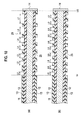
- a schematic cross section structure of the optical fiber 20 according to the first embodiment of the present invention corresponding to Fig. 9 is expressed as shown in Fig. 10(a)
- a schematic cross section structure of the optical fiber according to the comparative example is expressed as shown in Fig. 10(b) .
- the width L0 of the apertural area 23 is a given width, and is placed at equal intervals.
- the light power P (W/cm) is strong in the entrance part LI of the optical fiber, and the light power P (W/cm) is rapidly decreased as it shifts in the direction of length L of the longitudinal direction of the optical fiber towards the outlet part LO of the optical fiber.
- the width L1-L7 of the apertural area 23 is in the size relation of L1 ⁇ L2 ⁇ L3 ⁇ L4 ⁇ L5 ⁇ L6 ⁇ L7, and is narrowly formed in the entrance part LI of the optical fiber 20, and is formed so that it may become large gradually towards the outlet part LO from the entrance part LI, the light power P (W/cm) is not decreased rapidly, it decreases gradually or the essential almost flat output characteristic is obtained, as it shifts in the direction of length L of the longitudinal direction of the optical fiber 20.
- the optical fiber 20 according to the first embodiment of the present invention as shown in Fig.
- the optical fiber 20 related to the first embodiment of the present invention by adjusting the length L of the optical fiber 20 part by which the a plurality of apertural areas 23 are placed according to the length of the blood vessels, such as the coronary artery, and the relation of the inside diameter, it is also possible to set up the relation between the light power P (W/cm) and the length L so that it may decrease gradually or the essential almost flat output characteristic may be obtained, as shown by the dotted line of Fig. 9 .
- Fig. 14 shows an example of the refractive index profile of the optical fiber 20 according to the first embodiment of the present invention
- Fig. 14(a) shows an example whose refractive index n1 of the covering core layer 12 is high for the refractive index n0 of the glass core layer 11
- Fig. 14(b) shows an example whose refractive index n1 of the covering core layer 12 is low for the refractive index n0 of the glass core layer 11
- Fig. 14(c) shows an example refractive index n3 of the plastic core layer 21 is flat.
- the profile of the applicable refractive index n is expressed as shown in Fig. 14(a) to Fig. 14(c) .
- central-axis C-C of the longitudinal direction of the optical fiber 20 is set up as a central axis of the axis of coordinates, and the profile of the refractive index n of the direction of radius R is shown.
- the refractive index n0 of the glass core layer 11 is low set up a little rather than the refractive index n1 of the covering core layer 12.
- the refractive index n1 of the covering core layer 12 is set up higher than the refractive index n0 of the glass core layer 11, there is the effect that the light which flows through the optical fiber 20 becomes easy to perform the light guide of the covering core layer 12, thereby making easy to leak from the apertural area 23 placed at the cladding layer 13.
- the refractive index n3 of the cladding layer 13 is set up lower than the refractive index n0 of the glass core layer 11.
- the refractive index n1 of the covering core layer 12 and the refractive index n2 of the cladding layer 13 can be used combining the refractive index of the above-mentioned material suitably.
- the selection of the refractive index and material of the glass core layer 11, the covering core layer 12, and the cladding layer 13 is not limited above. It is selectable suitably in other plastic materials.
- the refractive index n0 of the glass core layer 11 can also be set up higher than the refractive index n1 of the covering core layer 12.
- the refractive index n1 of the covering core layer 12 lower than the refractive index n0 of the glass core layer 11
- the light which flows through the optical fiber 20 becomes easy to perform the light guide of the glass core layer 11 relatively, can perform the light guide of the longer distance in the glass core layer 11 of the optical fiber 20, and can be made easy to leak also from the apertural area 23 placed at the longer distance in the longitudinal direction of the optical fiber 20 from the entrance part in light. Therefore, in the case of the optical fiber 20 which has the refractive index profile of Fig. 14(b) , it is applicable at the use which sets up the length of the optical fiber 20 long.
- the optical fiber 20 according to the first embodiment of the present invention, as shown in Fig. 14(c) , it is also possible to use a plastic core layer 21 as the core layer.
- the refractive index profile of the refractive index n3 of the plastic core layer 21 has the flat profile, as shown in Fig. 14(c) . It can apply to the case where the power level of the light which penetrates through the optical fiber 20 is relatively low as the optical fiber 20 using the plastic core layer 21 which has the flat refractive index profile.
- a reflection mirror 14 is further placed in the trailer of the optical fiber 20.
- the metallic materials such as the nickel (Ni), the chromium (Cr), and the aluminum (Al), or the multilayer film can be used for the reflection mirror 14, for example.
- the diameter of the optical fiber according to the first embodiment of the present invention including the glass core layer 11, the covering core layer 12, and the cladding layer 13 is about 0.01 to several mm, preferable, is about 0.01 to 1 mm, and is selected according to the inside diameter of the organic tubular tissue to apply.
- the optical fiber 20 according to the first embodiment of the present invention can apply PDT (Photodynamic Therapy) by inserting in the organic tubular tissue, and can recover the lesion of the internal wall of organic tubular tissue completely.
- PDT Photodynamic Therapy
- the organism introduces the photosensitizer, the thrombus part which the medicine concentrated selectively is illuminated with the laser beam of the specific wavelength by using that the medicine of the photosensitizer concentrates selectively on the thrombus part which the atheroma, the cholesterol, etc. deposit, and the photochemical reaction can dissolve and remove the thrombus part.
- the photosensitizer When Antrin is used as the photosensitizer, for example, about 732 nm is the proper center wavelength as the wavelength of the laser beam.
- Photofrin or ALA is used as the photosensitizer, for example, about 630 nm is the proper center wavelength as the wavelength of the laser beam.
- Foscan is used as the photosensitizer, for example, about 652 nm is the proper center wavelength as the wavelength of the laser beam.
- LS11 When LS11 is used as the Photosensitizer, for example, about 654 nm is the proper center wavelength as the wavelength of the laser beam.
- the far-infrared wavelength can also be used from infrared with low dispersion absorption loss by the hemoglobin, etc. in the blood.
- the laser beam which has a wavelength of 1.0 to 1.3 ⁇ m (preferable near 1.1 ⁇ m), can be used.
- the laser beam which has the wavelength of 1.5 to 2.0 ⁇ m (preferable near 1.6 ⁇ m), can also be used.
- PDD Photodynamic Diagnosis
- the optical fiber 20 according to the first embodiment of the present invention is introduced in the organic tubular tissue, the lesion part is illuminated with the laser beam of the proper wavelength by using the medicine of the photosensitizer concentrating on the lesion part selectively according to the broadening range of the lesion part, the thrombus part adhering to the internal wall of the organic tubular tissue can be dissolved and removed, and the lesion can be recovered completely.
- the PDD Photodynamic Diagnosis
- the applied dose of the photosensitizer is about 2.5 mg, for example, and the power levels of the laser beam are about 150 J/cm ⁇ f -1 , for example (where f denotes a repeat frequency of the laser beam).
- f denotes a repeat frequency of the laser beam.
- the power level becomes about 150 mJ/cm.
- Such the laser beam illuminates about 500 sec, and then the thrombus part adhering to the internal wall of organic tubular tissue, etc. can be dissolved and removed.
- the optical power level is not limited to the above-mentioned numerical value range, and may use weaker power according to the use.
- the quality of the material of the glass core layer 11 can also be changed into plastics from silica.
- the inside diameter As for the blood vessels, such as a coronary artery, when inserting the optical fiber, there is the trend for the inside diameter to become thin as it goes to the end part although the inside diameter of the entrance part is generally thick.
- the PDT Photodynamic therapy
- adhering to the internal wall of the coronary artery can be dissolved and removed, by adjusting the length L of the optical fiber 20 part having the apertural area 23 to about 20 to 30 cm even if the length of the tubular tissue 15 is about 20 to 30 cm which is the length of the cardiac coronary artery, for example.
- FIG. 2 (a) is a schematic cross-sectional configuration diagram taken in the line I - I of Fig. 2(b)
- Fig. 2(b) is a schematic plan view of the optical fiber 20
- Fig. 2(c) is a schematic cross-sectional configuration diagram taken in the line II - II of Fig. 2(a)
- Fig. 2(d) shows a schematic cross-sectional configuration diagram taken in the line III - III of Fig. 2(a) .
- the optical fiber 20 is an optical fiber which can be inserted in a tubular tissue in an organism, and includes: a glass core layer 11; a covering core layer 12 which covers the glass core layer 11; and a cladding layer 13 which covers the covering core layer 12 and includes a plurality of apertural areas 23 having the given width L0 in the longitudinal direction of the optical fiber 20.
- the arrangement density of the apertural area 23 increases as it is distanced in the longitudinal direction of the optical fiber 20 from the entrance part of the optical fiber 20.
- the arrangement density of the apertural area 23 is defined by the overall length of the apertural area 23 per unit-length in the longitudinal direction of the optical fiber 20. That the arrangement density of the apertural area 23 is low in the entrance part of the optical fiber 20 means that the rate of the length of the apertural area 23 per unit-length in the longitudinal direction is relatively small in the entrance part of the optical fiber 20. That the arrangement density of the apertural area 23 is high means the rate of the length of the apertural area 23 per unit-length in the longitudinal direction of the optical fiber 20 is relatively large.
- the apertural area 23 has ring shape, as shown in Fig. 2 .
- a reflection mirror 14 is placed in the trailer of the optical fiber 20.
- the metallic materials such as the nickel (Ni), the chromium (Cr), and the aluminum (Al), or the multilayer film can be used for the reflection mirror 14, for example.
- the profile of the refractive index n applicable with the optical fiber 20 according to the second embodiment of the present invention is expressed as shown in Fig. 14(a) to Fig. 14(c) .
- selection of the material of each part and the value of the refractive index n are the same as that of the first embodiment.
- the relation between the light intensity P and the length L is expressed as the dotted line in Fig. 9 shows, as well as the optical fiber 20 according to the first embodiment of the present invention.
- the arrangement density of the apertural area 23 is relatively low in the entrance part LI of the optical fiber 20 and increases as it shifts from the entrance part LI to the direction of length L of the longitudinal direction of the optical fiber 20 towards the outlet part LO, the light power P (W/cm) is not decreased rapidly, it decreases gradually, or the essential almost flat output characteristic is obtained.
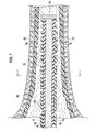
- Fig. 7 is a schematic cross-sectional configuration diagram for explaining the status that the optical fiber 20 according to the second embodiment of the present invention is inserted into a fluid medium 60 in an organic tubular tissue 15.
- the fluid medium 60 is blood etc. , for example.
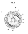
- Fig. 8 is a schematic cross-sectional configuration diagram taken in the line I - I of Fig. 7 . As shown in Fig. 7 and Fig.
- the thrombus part 16 adhering to the internal wall of the organic tubular tissue 15 can be dissolved and removed by also inserting the optical fiber 20 according to the second embodiment of the present invention into the organic tubular tissue 15, and applying the PDT (photodynamic therapy).
- the organism introduces the photosensitizer, the thrombus part 16 which the medicine concentrated selectively is illuminated with the laser beam of the specific wavelength by using that the medicine of the photosensitizer concentrates selectively on the thrombus part 16 which the atheroma, the cholesterol, etc. deposit, and the photochemical reaction can dissolve and remove the thrombi, such as the plaque layer.
- the relation between the photosensitizer and the wavelength of the laser beam is the same as that of the explanation in the first embodiment.
- FIG. 3(a) is a schematic cross-sectional configuration diagram taken in the line I - I of Fig. 3(b)
- Fig. 3(b) is a schematic plan view of the optical fiber 20
- Fig. 3(c) is a schematic cross-sectional configuration diagram taken in the line II - II of Fig. 3(a)
- Fig. 3(d) shows a schematic cross-sectional configuration diagram taken in the line III - III of Fig. 3(a) .
- the optical fiber 20 is an optical fiber which can be inserted in the tubular tissue in the organism, and includes: a glass core layer 11; a covering core layer 12 which covers the glass core layer 11; and a cladding layer 13 which covers the covering core layer 12 and includes a plurality of apertural areas 23 having constant width in the longitudinal direction of the optical fiber 20.
- the arrangement density of the apertural area 23 increases as it is distanced in the longitudinal direction from the entrance part of the optical fiber 20.
- the apertural area 23 has rectangular shape, as shown in Fig. 3 .
- a reflection mirror 14 is placed in the trailer of the optical fiber 20.
- the metallic materials such as the nickel (Ni), the chromium (Cr), and the aluminum (Al), or the multilayer film can be used for the reflection mirror 14, for example.
- the optical fiber 20 since the apertural area 23 has rectangular shape and the light is emitted only from the window part in which the apertural area 23 exists, when using the optical fiber 20 inserting in the organic tubular tissue, the optical fiber 20 may be used rotating around the central axis of the longitudinal direction.
- the profile of the refractive index n applicable with the optical fiber 20 according to the third embodiment of the present invention is expressed as shown in Fig. 14(a) to Fig. 14(c) .
- selection of the material of each part and the value of the refractive index n are the same as that of the first embodiment.
- the relation between the light intensity P and the length L is expressed as the dotted line in Fig. 9 shows, as well as the optical fiber 20 according to the first embodiment of the present invention.
- the arrangement density of the apertural area 23 is relatively low in the entrance part LI of the optical fiber 20 and increases as it shifts from the entrance part LI to the direction of length L of the longitudinal direction of the optical fiber 20 towards the outlet part LO, the light power P (W/cm) is not decreased rapidly, it decreases gradually, or the essential almost flat output characteristic is obtained.
- the thrombi such as the plaque layer, adhering to the internal wall of organic tubular tissue can be dissolved and removed by inserting also the optical fiber 20 according to the third embodiment of the present invention in the organic tubular tissue and applying the PDT (photodynamic therapy), as well as the optical fiber 20 according to the first embodiment.
- the organism introduces the photosensitizer, the thrombus part which the medicine concentrated selectively is illuminated with the laser beam of the specific wavelength using the medicine of the photosensitizer concentrating on the thrombus part which atheroma, the cholesterol, etc. deposited selectively, and thereby the photochemical reaction can dissolve and remove the thrombus part.
- the relation between the photosensitizer and the wavelength of the laser beam is the same as that of the explanation in the first embodiment.
- FIG. 4 (a) is a schematic cross-sectional configuration diagram taken in the line I - I of Fig. 4(b)
- Fig. 4(b) is a schematic plan view of the optical fiber 20
- Fig. 4(c) is a schematic cross-sectional configuration diagram taken in the line II - II Fig. 4(a)
- Fig. 4(d) shows a schematic cross-sectional configuration diagram taken in the line III - III of Fig. 4 (a) .
- the optical fiber 20 is an optical fiber which can be inserted in the tubular tissue in the organism, and includes: a glass core layer 11; a covering core layer 12 which covers the glass core layer 11; and a cladding layer 13 which covers the covering core layer 12 and includes a plurality of trench apertural areas (notches) 24 in the longitudinal direction of the optical fiber 20.
- the arrangement density of the trench apertural area (notch) 24 is relatively low in the entrance part of the optical fiber 20 and increases as it is distanced in the longitudinal direction of the optical fiber 20 from the entrance part.
- the trench apertural area 24 has ring shape.
- the trench apertural area 24 has the notch shape of the V-shaped groove, as shown in Fig. 4 .
- a reflection mirror 14 is placed in the trailer of the optical fiber 20.
- the metallic materials such as the nickel (Ni), the chromium (Cr), and the aluminum (Al), or the multilayer film can be used for the reflection mirror 14, for example.
- the profile of the refractive index n applicable with the optical fiber 20 according to the fourth embodiment of the present invention is expressed as shown in Fig. 14(a) to Fig. 14(c) .
- selection of the material of each part and the value of the refractive index n are the same as that of the first embodiment.
- the relation between the light intensity P and the length L is expressed as the dotted line in Fig. 9 shows, as well as the optical fiber 20 according to the first embodiment of the present invention.
- the arrangement density of the trench apertural area 24 is relatively low in the entrance part LI of the optical fiber 20 and increases as it shifts from the entrance part LI to the direction of length L of the longitudinal direction of the optical fiber 20 towards the outlet part LO, the light power P (W/cm) is not decreased rapidly, it decreases gradually, or the essential almost flat output characteristic is obtained.
- the thrombi adhering to the internal wall of organic tubular tissue can be dissolved and removed by inserting also the optical fiber 20 according to the fourth embodiment of the present invention in the organic tubular tissue and applying the PDT (photodynamic therapy), as well as the optical fiber 20 according to the first embodiment.
- the organism introduces the photosensitizer, the thrombus part which the medicine concentrated selectively is illuminated with the laser beam of the specific wavelength by using that the medicine of the photosensitizer concentrates selectively on the thrombus part which the atheroma, the cholesterol, etc. deposit, and thereby the photochemical reaction can dissolve and remove the thrombus part, such as the plaque layer.
- the relation between the photosensitizer and the wavelength of the laser beam is the same as that of the explanation in the first embodiment.
- FIG. 5(a) is a schematic cross-sectional configuration diagram taken in the line I - I of Fig. 5(b), and Fig. 5(b) shows a schematic plan view.
- the optical fiber 20 is an optical fiber 20 which can be inserted in the tubular tissue in the organism, and includes: a glass core layer 11; a covering core layer 12 which covers the glass core layer 11; and a cladding layer 13 which covers the covering core layer 12 and includes a spiral apertural area 23 in the longitudinal direction of the optical fiber 20.
- the arrangement density of the apertural area 23 is relatively low in the entrance part of the optical fiber 20 and increases as it is distanced in the longitudinal direction of the optical fiber 20 from the entrance part.
- the apertural area 23 has the given width L0 in the longitudinal direction of the optical fiber 20.
- a reflection mirror 14 is placed in the trailer of the optical fiber 20.
- the metallic materials such as the nickel (Ni), the chromium (Cr), and the aluminum (Al), or the multilayer film can be used for the reflection mirror 14, for example.
- the profile of the refractive index n applicable with the optical fiber 20 according to the fifth embodiment of the present invention is expressed as shown in Fig. 14(a) to Fig. 14(c) .
- selection of the material of each part and the value of the refractive index n are the same as that of the first embodiment.
- the relation between the light intensity P and the length L is expressed as the dotted line in Fig. 9 shows, as well as the optical fiber 20 according to the first embodiment of the present invention.
- the arrangement density of the apertural area 23 is relatively low in the entrance part LI of the optical fiber 20 and increases as it shifts from the entrance part LI to the direction of length L of the longitudinal direction of the optical fiber 20 towards the outlet part LO, the light power P (W/cm) is not decreased rapidly, it decreases gradually, or the essential almost flat output characteristic is obtained.
- the thrombi adhering to the internal wall of organic tubular tissue can be dissolved and removed by inserting also the optical fiber 20 according to the fifth embodiment of the present invention in the organic tubular tissue and applying the PDT (photodynamic therapy), as well as the optical fiber 20 according to the first embodiment.
- the organism introduces the photosensitizer, the thrombus part which the medicine concentrated selectively is illuminated with the laser beam of the specific wavelength using the medicine of the photosensitizer concentrating on the thrombus part which atheroma, the cholesterol, etc. deposited selectively, and thereby the photochemical reaction can dissolve and remove the thrombus part.
- the relation between the photosensitizer and the wavelength of the laser beam is the same as that of the explanation in the first embodiment.
- Fig. 6 (a) is a schematic cross-sectional configuration diagram taken in the line I - I of Fig. 6(b), and Fig. 6(b) shows a schematic plan view.
- the optical fiber 20 is an optical fiber 20 which can be inserted in the tubular tissue in the organism, and includes: a glass core layer 11; a covering core layer 12 which covers the glass core layer 11; and a cladding layer 13 which covers the covering core layer 12 and includes a spiral trench apertural area 24 in the longitudinal direction of the optical fiber 20.
- the arrangement density of the trench apertural area 24 is relatively low in the entrance part of the optical fiber 20 and increases as it is distanced in the longitudinal direction of the optical fiber 20 from the entrance part.
- the trench apertural area 24 has the notch shape of the V-shaped groove, as shown in Fig. 6 .
- a reflection mirror 14 is placed in the trailer of the optical fiber 20.
- the metallic materials such as the nickel (Ni), the chromium (Cr), and the aluminum (Al), or the multilayer film can be used for the reflection mirror 14, for example.
- the profile of the refractive index n applicable with the optical fiber 20 according to the sixth embodiment of the present invention is expressed as shown in Fig. 14(a) to Fig. 14(c) .
- selection of the material of each part and the value of the refractive index n are the same as that of the first embodiment.
- the relation between the light intensity P and the length L is expressed as the dotted line in Fig. 9 shows, as well as the optical fiber 20 according to the first embodiment of the present invention.
- the arrangement density of the trench apertural area 24 is relatively low in the entrance part LI of the optical fiber 20 and increases as it shifts from the entrance part LI to the direction of length L of the longitudinal direction of the optical fiber 20 towards the outlet part LO, the light power P (W/cm) is not decreased rapidly, it decreases gradually, or the essential almost flat output characteristic is obtained.
- the thrombi adhering to the internal wall of organic tubular tissue can be dissolved and removed by inserting also the optical fiber 20 according to the sixth embodiment of the present invention in the organic tubular tissue and applying the PDT (photodynamic therapy), as well as the optical fiber 20 according to the first embodiment.
- the organism introduces the photosensitizer, the thrombus part which the medicine concentrated selectively is illuminated with the laser beam of the specific wavelength using the medicine of the photosensitizer concentrating on the thrombus part which atheroma, the cholesterol, etc. deposited selectively, and thereby the photochemical reaction can dissolve and remove the thrombus part.
- the relation between the photosensitizer and the wavelength of the laser beam is the same as that of the explanation in the first embodiment.
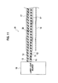
- Fig. 11 shows a schematic configuration diagram of an optical fiber device 26 which applies the optical fiber 20 according to the first to sixth embodiments of the present invention.
- Fig. 11 since the detailed configuration of the apertural area of the optical fiber 20 is the same as that of the optical fiber 20 according to the first to sixth embodiments of the present invention, illustration is omitted.
- the optical fiber device 26 includes: a laser light source 19; an optical fiber 20 which is connected to the laser light source 19 and is the optical fiber according to the first to sixth embodiments of the present invention; a guidewire 18 by which adjacent disposition is performed to the optical fiber 20; and a catheter 17 which inserts the optical fiber 20.
- the guidewire 18 by which adjacent disposition is performed to the optical fiber 20 may be inserted into the catheter 17 which inserts the optical fiber 20.
- the optical fiber device 26 according to the seventh embodiment of the present invention is simple for the configuration of the whole device, and the light weight and the miniaturization are easy also for the laser light source by applying the semiconductor laser etc.
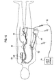
- the cardiac catheter operation or examination using the optical fiber device 26 which applies the optical fiber 20 according to the first to sixth embodiments of the present invention is schematically expressed as shown in Fig. 12 .
- the optical fiber 20 connected to the laser light source 19 is inserted from the femoral artery 48, and is made to reach in the heart 50 through the aorta abdominalis 44.
- the optical fiber 20 connected to the laser light source 19 is inserted from the radial artery 46 or the elbow part artery 52, and may be made to reach in the heart 50.
- Fig. 13(a) is an enlarged drawing of a part of A of Fig. 13(a)
- Fig. 13(c) is an enlarged drawing of a part of B of Fig. 13(a) .
- the optical fiber 20 which reached in the heart 50 via the aorta 36 near the heart 50 is inserted into the right coronary artery 30, the left anterior descending artery 32, or the left coronary artery circumflex artery 42, for example.
- Fig. 13(b) shows an example by which the optical fiber 20 is inserted into the right coronary artery 30.
- Fig. 13(c) shows an example by which the optical fiber 20 is inserted into the left anterior descending artery 32.
- the optical fiber 20 may be inserted into the large vein 34, the pulmonary vein 38, or the pulmonary artery 40.
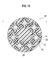
- Fig. 15 shows an optical fiber according to the eighth embodiment of the present invention, and shows a schematic cross-sectional configuration diagram which composed the optical fiber 20 shown in the third embodiment of the present invention in the optical fiber bundle.
- Fig. 16 shows a modified example of an optical fiber according to the eighth embodiment of the present invention.
- Fig. 17 shows the optical fiber according to the eighth embodiment of the present invention, and shows a schematic plan view which composes the optical fiber 20 shown in the third embodiment of the present invention in the optical fiber bundle.
- Both of Fig. 15 and Fig. 16 correspond to a schematic cross-sectional configuration diagram taken in the line I - I of Fig. 17 .
- a schematic plan view is similarly shown to be Fig. 17 .
- Fig. 18 shows a schematic cross-sectional configuration diagram for explaining the status that the optical fiber bundle 22 shown in Fig. 15 is inserted into the fluid medium 60 of the organic tubular tissue 15.
- Fig. 19 shows a schematic cross-sectional configuration diagram for explaining the status that the optical fiber bundle 22 shown in Fig. 16 is inserted into the fluid medium 60 of the organic tubular tissue 15.
- the fluid medium 60 is blood etc.
- the optical fiber according to the eighth embodiment of the present invention composes the optical fiber bundle 22, and is composed of a plurality of optical fibers which can be inserted in the tubular tissue in the organism.
- Each optical fiber includes: a glass core layer 11; a covering core layer 12 which covers the glass core layer 11; and a cladding layer 13 which covers the covering core layer 12 and includes a plurality of apertural areas 23 having constant width in the longitudinal direction of the optical fiber.
- the arrangement density of the apertural area 23 is relatively low in the entrance part of the optical fiber and increases as it is distanced in the longitudinal direction of the optical fiber from the entrance part, and each optical fiber of each other is adhered via the adhesive layer 25 to make it as the bundle.
- Each optical fiber which composes the optical fiber bundle 22 according to the eighth embodiment of the present invention is not limited to the optical fiber 20 according to the third embodiment of the present invention, and can all apply the optical fiber 20 explained in the first to sixth embodiments of the present invention. Furthermore, according to the use, it may combine a plurality of kinds of optical fibers 20 explained in the first to sixth embodiments.
- the optical fiber according to the modified example of the eighth embodiment of the present invention provides the cavity portion 62 of the central part of a plurality of optical fibers with the guidewire 18, as shown in Fig. 16 .
- Fig. 16 By adopting the configuration of Fig. 16 , it becomes unnecessary to place the guidewire 18 separately to external of the plurality of optical fibers, and thereby the space-saving and the miniaturization of the optical fiber and the optical fiber device can be accelerated.
- the apertural area 23 of each optical fiber may be provided with ring shape, the swirl shape, or the notch shape of the V-shaped groove.
- a reflection mirror 14 is placed in the trailer of the optical fiber bundle 22.
- the metallic materials such as the nickel (Ni), the chromium (Cr), and the aluminum (Al), or the multilayer film can be used for the reflection mirror 14, for example.
- the position of the apertural area 23 of each optical fiber 20 is completed to be placed when composed as the optical fiber bundle 22 in the example shown in Fig. 17 , but it is not necessary to complete the position of the apertural area 23, and it may be shifted to be placed.
- the diameter of the optical fiber bundle 22 shown in the eighth embodiment of the present invention is about 0.1 mm to several mm, is about 0.1 mm to about 1 mm preferable, and is selected according to the number of the bundle, and the inside diameter of organic tubular tissue to apply.
- the diameter of the optical fiber bundle applied to the eighth embodiment of the present invention in the case where the diameter of each optical fiber including the glass core layer 11, the covering core layer 12, and the cladding layer 13 is about 0.1 mm, if the bundle number is 7 as shown in Fig. 15 , the diameter of the optical fiber bundle will be about 0.2 mm to about 0.4 mm.
- the plastic core layer 21 is used instead of the glass core layer 11, it can form still more thinly.
- the profile of the refractive index n applicable with each optical fiber 20 is expressed as shown in Fig. 14(a) to Fig. 14(c) , as well as the first embodiment. Moreover, selection of the material of each part and the value of the refractive index n are the same as that of the first embodiment.
- the optical fiber bundle 22 shown in the eighth embodiment of the present invention since the arrangement density of the apertural area 23 is relatively low in the entrance part LI of the optical fiber and increases as it shifts from the entrance part LI to the direction of length L of the longitudinal direction of the optical fiber towards the outlet part LO, the light power P (W/cm) is not decreased rapidly, it decreases gradually, or the essential almost flat output characteristic is obtained. Therefore, as for the relation between the light intensity P and the length L, the same characteristics as the characteristics shown by the dotted line in Fig. 9 are obtained, as well as the optical fiber according to the first embodiment of the present invention. Since it is made as the bundle, the light intensity P becomes large the several times to several tens times, for example, according to the number of the optical fiber.
- the optical fiber according to the eighth embodiment of the present invention and its modified example, the thrombus part 16 adhering to the internal wall of the organic tubular tissue 15 can be dissolved and removed by inserting in the organic tubular tissue 15 and applying the PDT (photodynamic therapy), as well as the optical fiber according to the first embodiment.
- the relation between the photosensitizer and the wavelength of the laser beam is the same as that of the explanation in the first embodiment.
- the optical fiber according to the eighth embodiment of the present invention since the relation between the light power P (W/cm) and the length L is decreased gradually or the essential almost flat output characteristic is obtained, even if the length of the tubular tissue 15 is about 20 cm to 30 cm which is the length of the cardiac coronary artery, for example, by adjusting the length L of the optical fiber part having the apertural area 23 to about 20 cm to 30 cm, and applying the PDT (Photodynamic therapy) to the whole coronary artery, the thrombus part 16, etc. adhering to the internal wall of the coronary artery can be dissolved and removed.
- PDT Photodynamic therapy
- the tubular tissues 15 with which the optical fiber bundle 22 shown in the eighth embodiment of the present invention is applied is the blood vessel, the pancreatic duct, the bile duct, the trachea, the mammary gland, lactiferous ducts, the urinary duct, etc.
- optical fiber, optical fiber device, and optical fiber bundle of the present invention it is applied to organic tubular tissue, and the lesion region of the internal wall of tubular tissue can be removed selectively.
- the laser beam of high intensity can be transmitted by using silica for the core of the optical fiber in particular.
Landscapes
- Health & Medical Sciences (AREA)
- Physics & Mathematics (AREA)
- Life Sciences & Earth Sciences (AREA)
- Engineering & Computer Science (AREA)
- Biomedical Technology (AREA)
- Optics & Photonics (AREA)
- Surgery (AREA)
- Nuclear Medicine, Radiotherapy & Molecular Imaging (AREA)
- Animal Behavior & Ethology (AREA)
- General Health & Medical Sciences (AREA)
- Public Health (AREA)
- Veterinary Medicine (AREA)
- General Physics & Mathematics (AREA)
- Radiology & Medical Imaging (AREA)
- Electromagnetism (AREA)
- Otolaryngology (AREA)
- Pathology (AREA)
- Heart & Thoracic Surgery (AREA)
- Medical Informatics (AREA)
- Molecular Biology (AREA)
- Biophysics (AREA)
- Radiation-Therapy Devices (AREA)
- Laser Surgery Devices (AREA)
- Light Guides In General And Applications Therefor (AREA)
- Optical Fibers, Optical Fiber Cores, And Optical Fiber Bundles (AREA)
Abstract
Description
- The present invention relates to an optical fiber, an optical fiber device, and an optical fiber bundle, and in particular, relates to an optical fiber, an optical fiber device, and an optical fiber bundle of a medical application, which are applied to an organic tubular tissue.
- In an organic tubular tissue represented by a cardiac coronary artery blood vessel etc., a thrombus layer adheres to the wall part. The thrombus layer is a layer of cholesterol including padding of a fat and many calcium ingredients. In recent years, as a method to improve obstruction by the thrombus of a coronary artery, etc., there are a recanalization method by a balloon called the percutaneous menstrual blood vessel coronary artery plasty or PTCA (Percutaneous Transluminal Coronary Angioplasty), and a semipermanent recanalization method called a stent. However, since there are the problems, such as the generation of a restenosis, it cannot become a perfect therapeutic method.
- On the other hand, PDT (Photodynamic Therapy) is a therapy which the organism introduces a photosensitizer, illuminates with the light of the specific wavelength a part of a cancer which a medicine concentrated selectively using the medicine of the photosensitizer concentrating on the part of cancers, such as a stomach and a lung, selectively, and collapses the cancer cell. Moreover, PDD (Photodynamic Diagnosis) is a diagnosing method which illuminates with the light of the specific wavelength using the medicine of the photosensitizer concentrating on the part of cancers, such as the stomach and the lung, selectively, and grips a broadening range of the cancer cells, such as the stomach and the lung, from the fluorescence.
- On the other hand, in the use of an optical fiber sensor as a surface treatment technology by an optical fiber, it is already disclosed in
Patent Literature 1 about a method of forming a plurality of notches on the surface of the optical fiber.
Patent Literature 1: Published Japanese translations of PCT International Publication for Patent Application No.H08-511343
Although the Photodynamic Therapy (PDT) or the Photodynamic Diagnosis (PDD) is applied to the part of cancers, such as the stomach and the lung, as above-mentioned, the PDT or the PDD is not applied to a lesion region in the tubular tissue of an organic narrow diameter represented in a cardiac coronary artery blood vessel etc. - The object of the present invention is to provide an optical fiber, an optical fiber device, and an optical fiber bundle of the medical application for being applied to organic tubular tissue and treating the lesion region of tubular tissue.
- According to one aspect of the present invention, an optical fiber which can be inserted in a tubular tissue in an organism, the optical fiber comprising: a glass core layer; a covering core layer which covers the glass core layer; and a cladding layer which covers the covering core layer and includes a plurality of apertural areas in a longitudinal direction of the optical fiber, wherein a width of the apertural area in the longitudinal direction of the optical fiber is narrowly formed in an entrance part of the optical fiber, and is widely formed as to be distanced in the longitudinal direction of the optical fiber from the entrance part, is provided.
- According to another aspect of the present invention, an optical fiber which can be inserted in a tubular tissue in an organism, the optical fiber comprising: a glass core layer; a covering core layer which covers the glass core layer; and a cladding layer which covers the covering core layer and includes a plurality of apertural areas having constant width in a longitudinal direction of the optical fiber, wherein an arrangement density of the apertural area increases as to be distanced in the longitudinal direction of the optical fiber from an entrance part of the optical fiber, is provided.
- According to another aspect of the present invention, an optical fiber which can be inserted in a tubular tissue in an organism, the optical fiber comprising: a glass core layer; a covering core layer which covers the glass core layer; and a cladding layer which covers the covering core layer and includes a spiral apertural area in a longitudinal direction of the optical fiber, wherein an arrangement density of the apertural area increases as to be distanced in the longitudinal direction of the optical fiber from an entrance part of the optical fiber, is provided.
- According to another aspect of the present invention, an optical fiber which can be inserted in a tubular tissue in an organism, the optical fiber comprising: a core layer; and a cladding layer which covers the core layer and includes a plurality of apertural areas having constant width in a longitudinal direction of the optical fiber, wherein an arrangement density of the apertural area increases as to be distanced in the longitudinal direction of the optical fiber from an entrance part of the optical fiber, is provided.
- According to another aspect of the present invention, an optical fiber device comprising: a laser light source; and an optical fiber connected to the laser light source, the optical fiber comprising a glass core layer, a covering core layer which covers the glass core layer, and a cladding layer which covers the covering core layer and including a plurality of apertural areas in a longitudinal direction of the optical fiber, a width of the apertural area in the longitudinal direction of the optical fiber is narrowly formed in an entrance part of the optical fiber and is widely formed as to be distanced in the longitudinal direction of the optical fiber from the entrance part, the optical fiber which can be inserted in a tubular tissue in an organism, is provided.
- According to another aspect of the present invention, an optical fiber device comprising: a laser light source; and an optical fiber connected to the laser light source, the optical fiber comprising a glass core layer, a covering core layer which covers the glass core layer, and a cladding layer which covers the covering core layer and includes a plurality of apertural areas having constant width in a longitudinal direction of the optical fiber, an arrangement density of the apertural area increases as to be distanced in the longitudinal direction of the optical fiber from an entrance part of the optical fiber, the optical fiber which can be inserted in a tubular tissue in an organism, is provided.
- According to another aspect of the present invention, an optical fiber device comprising: a laser light source; and an optical fiber connected to the laser light source, the optical fiber comprising a glass core layer, a covering core layer which covers the glass core layer, and a cladding layer which covers the covering core layer and includes a spiral apertural area in a longitudinal direction of the optical fiber, an arrangement density of the apertural area increases as to be distanced in the longitudinal direction of the optical fiber from an entrance part of the optical fiber, the optical fiber which can be inserted in a tubular tissue in an organism, is provided.
- According to another aspect of the present invention, an optical fiber bundle comprising a plurality of optical fibers which can be inserted in a tubular tissue in an organism, each the optical fiber comprising: a glass core layer; a covering core layer which covers the glass core layer; and a cladding layer which covers the covering core layer and including a plurality of apertural areas in a longitudinal direction of the optical fiber, wherein a width of the apertural area in the longitudinal direction of the optical fiber is narrowly formed in an entrance part of the optical fiber, and is widely formed as to be distanced in the longitudinal direction of the optical fiber from the entrance part, and each the optical fiber adheres via an adhesive layer mutually, is provided.
- According to another aspect of the present invention, an optical fiber bundle comprising a plurality of optical fibers which can be inserted in a tubular tissue in an organism, each the optical fiber comprising: a glass core layer; a covering core layer which covers the glass core layer; and a cladding layer which covers the covering core layer and includes a plurality of apertural areas having constant width in a longitudinal direction of the optical fiber, wherein an arrangement density of the apertural area increases as to be distanced in the longitudinal direction of the optical fiber from an entrance part of the optical fiber, and each the optical fiber adheres via an adhesive layer mutually, is provided.
- According to another aspect of the present invention, an optical fiber bundle comprising a plurality of optical fibers which can be inserted in a tubular tissue in an organism, each the optical fiber comprising: a glass core layer; a covering core layer which covers the glass core layer; and a cladding layer which covers the covering core layer and includes a spiral apertural area in a longitudinal direction of the optical fiber, wherein an arrangement density of the apertural area increases as to be distanced in the longitudinal direction of the optical fiber from an entrance part of the optical fiber, and each the optical fiber adheres via an adhesive layer mutually, is provided.
-
- [
Fig. 1 ] An optical fiber according to a first embodiment of the present invention,- (a) a schematic cross-sectional configuration diagram taken in the line I - I of (b),
- (b) a schematic plan view,
- (c) a schematic cross-sectional configuration diagram taken in the line II - II of (a), and
- (d) a schematic cross-sectional configuration diagram taken in the line III - III of (a).
- [
Fig. 2 ] An optical fiber according to a second embodiment of the present invention,- (a) a schematic cross-sectional configuration diagram taken in the line I - I of (b),
- (b) a schematic plan view,
- (c) a schematic cross-sectional configuration diagram taken in the line II - II of (a), and
- (d) a schematic cross-sectional configuration diagram taken in the line III - III of (a).
- [
Fig. 3 ] An optical fiber according to a third embodiment of the present invention,- (a) a schematic cross-sectional configuration diagram taken in the line I - I of (b),
- (b) a schematic plan view,
- (c) a schematic cross-sectional configuration diagram taken in the line II - II of (a), and
- (d) a schematic cross-sectional configuration diagram taken in the line III - III of (a).
- [
Fig. 4 ] An optical fiber according to a fourth embodiment of the present invention,- (a) a schematic cross-sectional configuration diagram taken in the line I - I of (b),
- (b) a schematic plan view,
- (c) a schematic cross-sectional configuration diagram taken in the line II - II of (a), and
- (d) a schematic cross-sectional configuration diagram taken in the line III - III of (a).
- [
Fig. 5 ] An optical fiber according to a fifth embodiment of the present invention,- (a) a schematic cross-sectional configuration diagram taken in the line I - I of (b), and
- (b) a schematic plan view.
- [
Fig. 6 ] An optical fiber according to a sixth embodiment of the present invention,- (a) a schematic cross-sectional configuration diagram taken in the line I - I of (b), and
- (b) a schematic plan view.
- [
Fig. 7 ] A schematic cross-sectional configuration diagram for explaining a status that the optical fiber according to the second embodiment of the present invention is inserted in organic tubular tissue. - [
Fig. 8 ] A schematic cross-sectional configuration diagram taken in the line I - I ofFig. 7 . - [
Fig. 9 ] A schematic diagram showing the relation between the light intensity P and length L, in the optical fiber according to the first embodiment of the present invention and an optical fiber according to a comparative example. - [
Fig. 10 ]- (a) a schematic cross-sectional configuration diagram of the optical fiber according to the first embodiment of the present invention, and
- (b) a schematic cross-sectional configuration diagram of the optical fiber according to a comparative example.
- [
Fig. 11 ] A schematic configuration diagram of an optical fiber device which applies the optical fiber according to the first to sixth embodiments of the present invention. - [
Fig. 12 ] A schematic diagram for explaining an aspect of a cardiac catheter operation or an examination using an optical fiber device which applies the optical fiber according to the first to sixth embodiments of the present invention. - [
Fig. 13 ] In the cardiac catheter operation or the examination using the optical fiber device which applies the optical fiber according to the first to sixth embodiments of the present invention,- (a) a figure for explaining an aspect that the optical fiber according to the first to sixth embodiments of the present invention is inserted in the cardiac coronary artery part,
- (b) an enlarged drawing of the part of A, and
- (c) an enlarged drawing of the part of B.
- [
Fig. 14 ] An example of a refractive index profile of the optical fiber related to the first to sixth embodiments of the present invention,- (a) an example whose refractive index n1 of a covering core layer is high, for a refractive index n0 of glass core layer,
- (b) an example whose refractive index n1 of a covering core layer is low, for a refractive index n0 of glass core layer, and
- (c) an example whose refractive index n3 of plastic core layer is the flat.
- [
Fig. 15 ] A schematic cross-sectional configuration diagram which is the optical fiber according to the eighth embodiment of the present invention, and is taken in the line I - I ofFig. 17 showing an example which composes the optical fiber according to the third embodiment of the present invention into an optical fiber bundle. - [
Fig. 16 ] A schematic cross-sectional configuration diagram of an optical fiber according to a modified example of the eighth embodiment of the present invention. - [
Fig. 17 ] A schematic plan view which is the optical fiber according to the eighth embodiment of the present invention, and composes the optical fiber according to the third embodiment of the present invention into the optical fiber bundle. - [
Fig. 18 ] A schematic cross-sectional configuration diagram for explaining the status that the optical fiber bundle shown inFig. 15 is inserted in organic tubular tissue. - [
Fig. 19 ] A schematic cross-sectional configuration diagram for explaining the status that the optical fiber bundle shown inFig. 16 is inserted in organic tubular tissue. - Next, an embodiment of the invention is described with reference to drawings. In the description of the following drawings, the identical or similar reference numeral is attached to the identical or similar part. However, a drawing is schematic and it should care about differing from an actual thing. Of course, the part from which the relation and ratio of a mutual size differ also in mutually drawings is included.
- The embodiment shown in the following exemplifies the device and method for materializing the technical idea of this invention, and the technical idea of this invention does not specify placement of each component parts, etc. as the following. The technical idea of this invention can add various change in scope of claims.
- Moreover, an optical fiber, an optical fiber device, and an optical fiber bundle according to the embodiments of the present invention can provide the means for removing a lesion part of internal wall of organic tubular tissue by using together with PDT (Photodynamic Therapy) or PDD (Photodynamic Diagnosis).
- Furthermore, the optical fiber, the optical fiber device, and the optical fiber bundle according to the embodiments of the present invention can provide the diagnosing method and the operating method for removing the lesion part of the organic tubular tissue internal wall, by using together with PDT (Photodynamic Therapy) or PDD (Photodynamic Diagnosis).
- In addition, in the explanation of the embodiments of the present invention, the tubular tissue indicates a blood vessel, a pancreatic duct, a bile duct, a trachea, a mammary gland, lactiferous ducts, a urinary duct, etc., for example. In particular, all the blood vessels that include a part which the infarction and obstruction generate by atheroma, the thrombus, etc. about the blood vessel not only including a cardiac coronary artery but including a brain artery, a pulmonary vein, carotid arteries, and an artery and a vein of abdominal part and hand and foot, are applicable.
- Moreover, in the embodiments of the present invention, as shown in
Fig. 10 , the outlet part LO of the optical fiber is a part by which thereflection mirror 14 is placed, and as shown inFig. 10 , the entrance part LI of the optical fiber is a part by which the firstapertural area 23 is placed in view of the laser light source. - Moreover, in the embodiments of the present invention, the arrangement density of the
apertural area 23 is defined by the overall length of theapertural area 23 per unit-length in the longitudinal direction of theoptical fiber 20. That the arrangement density of theapertural area 23 is low means that the rate of the length of theapertural area 23 per unit-length in the longitudinal direction is relatively low. That the arrangement density of theapertural area 23 is high means that the rate of the length of theapertural area 23 per unit-length in the longitudinal direction of theoptical fiber 20 is relatively high. - An
optical fiber 20 according to the first embodiment of the present invention is expressed as shown inFig. 1. Fig. 1(a) is a schematic cross-sectional configuration diagram taken in the line I - I ofFig. 1(b), Fig. 1(b) is a schematic plan view of theoptical fiber 20,Fig. 1(c) is a schematic cross-sectional configuration diagram taken in the line II - II ofFig. 1(a), and Fig. 1(d) shows a schematic cross-sectional configuration diagram taken in the line III - III ofFig. 1(a) . - As shown in
Fig. 1 , theoptical fiber 20 according to the first embodiment of the present invention is an optical fiber which can be inserted in a tubular tissue in an organism, and includes: aglass core layer 11; acovering core layer 12 which covers theglass core layer 11; and acladding layer 13 which covers thecovering core layer 12 and includes a plurality ofapertural areas 23 in the longitudinal direction of theoptical fiber 20. In the longitudinal direction of theoptical fiber 20, the width L1-L7 of theapertural area 23 is in the size relation of L1<L2<L3<L4<L5<L6<L7, and it is narrowly formed in the entrance part of theoptical fiber 20 and is widely formed as it is distanced in the longitudinal direction of theoptical fiber 20 from the entrance part. - In this case, in the first embodiment of the present invention, as shown in
Fig. 10 , the outlet part LO of the optical fiber is a part by which areflection mirror 14 is placed, and as shown inFig. 10 , the entrance part LI of the optical fiber is a part by which the firstapertural area 23 is placed in view of the laser light source. - Moreover, in the
optical fiber 20 according to the first embodiment of the present invention, theapertural area 23 has ring shape, as shown inFig. 1 . - In the optical fiber according to the first embodiment of the present invention and an optical fiber according to a comparative example, the relation between the light intensity P and length L is expressed, as shown in
Fig. 9 . A schematic cross section structure of theoptical fiber 20 according to the first embodiment of the present invention corresponding toFig. 9 is expressed as shown inFig. 10(a) , and a schematic cross section structure of the optical fiber according to the comparative example is expressed as shown inFig. 10(b) . - In the optical fiber according to the comparative example, as shown in
Fig. 10(b) , the width L0 of theapertural area 23 is a given width, and is placed at equal intervals. As shown by the full line ofFig. 9 , the light power P (W/cm) is strong in the entrance part LI of the optical fiber, and the light power P (W/cm) is rapidly decreased as it shifts in the direction of length L of the longitudinal direction of the optical fiber towards the outlet part LO of the optical fiber. In the optical fiber according to the comparative example, this is because almost all light power P (W/cm) will leak near the entrance part LI of the optical fiber since the width LO of theapertural area 23 is a given width and is placed at equal intervals, as shown inFig. 10(b) . - As compared with this, in the
optical fiber 20 according to the first embodiment of the present invention, as shown inFig. 10(a) , since the width L1-L7 of theapertural area 23 is in the size relation of L1<L2<L3<L4<L5<L6<L7, and is narrowly formed in the entrance part LI of theoptical fiber 20, and is formed so that it may become large gradually towards the outlet part LO from the entrance part LI, the light power P (W/cm) is not decreased rapidly, it decreases gradually or the essential almost flat output characteristic is obtained, as it shifts in the direction of length L of the longitudinal direction of theoptical fiber 20. In theoptical fiber 20 according to the first embodiment of the present invention, as shown inFig. 10(a) , this is because leakage of light power P (W/cm) near the entrance part LI of theoptical fiber 20 is suppressed since the width of theapertural area 23 is formed narrowly near the entrance part LI of theoptical fiber 20, and is formed so that it may become large gradually towards outlet part LO from the entrance part LI. - As for the blood vessels, such as a coronary artery, when inserting the optical fiber, there is the trend for the inside diameter to become thin as it goes to the end part although the inside diameter of the entrance part is generally thick. In the
optical fiber 20 related to the first embodiment of the present invention, by adjusting the length L of theoptical fiber 20 part by which the a plurality ofapertural areas 23 are placed according to the length of the blood vessels, such as the coronary artery, and the relation of the inside diameter, it is also possible to set up the relation between the light power P (W/cm) and the length L so that it may decrease gradually or the essential almost flat output characteristic may be obtained, as shown by the dotted line ofFig. 9 . -
Fig. 14 shows an example of the refractive index profile of theoptical fiber 20 according to the first embodiment of the present invention,Fig. 14(a) shows an example whose refractive index n1 of thecovering core layer 12 is high for the refractive index n0 of theglass core layer 11,Fig. 14(b) shows an example whose refractive index n1 of thecovering core layer 12 is low for the refractive index n0 of theglass core layer 11, andFig. 14(c) shows an example refractive index n3 of theplastic core layer 21 is flat. - In the
optical fiber 20 according to the first embodiment of the present invention, the profile of the applicable refractive index n is expressed as shown inFig. 14(a) to Fig. 14(c) . InFig. 14 , central-axis C-C of the longitudinal direction of theoptical fiber 20 is set up as a central axis of the axis of coordinates, and the profile of the refractive index n of the direction of radius R is shown. - In the
optical fiber 20 according to the first embodiment of the present invention, as shown inFig. 14(a) , the refractive index n0 of theglass core layer 11 is low set up a little rather than the refractive index n1 of thecovering core layer 12. Thus, by setting up the refractive index n1 of thecovering core layer 12 higher than the refractive index n0 of theglass core layer 11, there is the effect that the light which flows through theoptical fiber 20 becomes easy to perform the light guide of thecovering core layer 12, thereby making easy to leak from theapertural area 23 placed at thecladding layer 13. Moreover, the refractive index n3 of thecladding layer 13 is set up lower than the refractive index n0 of theglass core layer 11. As a typical numerical value, n0=1.4585, n1=1.46 to 1.53, and n3=1.38 to 1.4 are preferable, for example. - When silica is used for the
glass core layer 11, for example, the refractive index n0=1.4585 is obtained. As a material of thecovering core layer 12, when the silicone resin is used, for example, the refractive index n1=1.52 is obtained. Moreover, when epoxy acrylate based resin is used, for example, the refractive index n1=1.543 is obtained. Moreover, when ethyl carbamate acrylate based resin is used, for example, the refractive index n1=1.49 to 1.52, 1.510 to 1.513, or 1.490 to 1.540 is obtained. - On the other hand, as a material of the
cladding layer 13, when the silicone resin for silicone clad is used, for example, the refractive index n2=1.41 is obtained. Moreover, when fluoridation acrylate based resin is used, for example, the refractive index n2=1.38 or 1.40 is obtained. Moreover, when ethyl carbamate acrylate based resin is used, for example, the refractive index n2=1.470 to 1.490 is obtained. - The refractive index n1 of the
covering core layer 12 and the refractive index n2 of thecladding layer 13 can be used combining the refractive index of the above-mentioned material suitably. The selection of the refractive index and material of theglass core layer 11, thecovering core layer 12, and thecladding layer 13 is not limited above. It is selectable suitably in other plastic materials. - On the other hand, in the
optical fiber 20 according to the first embodiment of the present invention, as shown inFig. 14(b) , the refractive index n0 of theglass core layer 11 can also be set up higher than the refractive index n1 of thecovering core layer 12. Thus, by setting up the refractive index n1 of thecovering core layer 12 lower than the refractive index n0 of theglass core layer 11, the light which flows through theoptical fiber 20 becomes easy to perform the light guide of theglass core layer 11 relatively, can perform the light guide of the longer distance in theglass core layer 11 of theoptical fiber 20, and can be made easy to leak also from theapertural area 23 placed at the longer distance in the longitudinal direction of theoptical fiber 20 from the entrance part in light. Therefore, in the case of theoptical fiber 20 which has the refractive index profile ofFig. 14(b) , it is applicable at the use which sets up the length of theoptical fiber 20 long. - Furthermore, in the
optical fiber 20 according to the first embodiment of the present invention, as shown inFig. 14(c) , it is also possible to use aplastic core layer 21 as the core layer. The refractive index profile of the refractive index n3 of theplastic core layer 21 has the flat profile, as shown inFig. 14(c) . It can apply to the case where the power level of the light which penetrates through theoptical fiber 20 is relatively low as theoptical fiber 20 using theplastic core layer 21 which has the flat refractive index profile. - Moreover, in the
optical fiber 20 according to the first embodiment of the present invention, as shown inFig. 1 , areflection mirror 14 is further placed in the trailer of theoptical fiber 20. The metallic materials, such as the nickel (Ni), the chromium (Cr), and the aluminum (Al), or the multilayer film can be used for thereflection mirror 14, for example. - In addition, the diameter of the optical fiber according to the first embodiment of the present invention including the
glass core layer 11, thecovering core layer 12, and thecladding layer 13 is about 0.01 to several mm, preferable, is about 0.01 to 1 mm, and is selected according to the inside diameter of the organic tubular tissue to apply. - The
optical fiber 20 according to the first embodiment of the present invention can apply PDT (Photodynamic Therapy) by inserting in the organic tubular tissue, and can recover the lesion of the internal wall of organic tubular tissue completely. The organism introduces the photosensitizer, the thrombus part which the medicine concentrated selectively is illuminated with the laser beam of the specific wavelength by using that the medicine of the photosensitizer concentrates selectively on the thrombus part which the atheroma, the cholesterol, etc. deposit, and the photochemical reaction can dissolve and remove the thrombus part. - When Antrin is used as the photosensitizer, for example, about 732 nm is the proper center wavelength as the wavelength of the laser beam. When Photofrin or ALA is used as the photosensitizer, for example, about 630 nm is the proper center wavelength as the wavelength of the laser beam. When Foscan is used as the photosensitizer, for example, about 652 nm is the proper center wavelength as the wavelength of the laser beam. When LS11 is used as the Photosensitizer, for example, about 654 nm is the proper center wavelength as the wavelength of the laser beam.
- Moreover, the far-infrared wavelength can also be used from infrared with low dispersion absorption loss by the hemoglobin, etc. in the blood. For example, the laser beam, which has a wavelength of 1.0 to 1.3 µm (preferable near 1.1 µm), can be used. Alternatively, the laser beam, which has the wavelength of 1.5 to 2.0 µm (preferable near 1.6 µm), can also be used.
- It is also possible to provide a diagnosing method which grips the broadening range of the lesion part using the medicine of the photosensitizer concentrating on the lesion part selectively, by using the PDD (Photodynamic Diagnosis) together with such the PDT (photodynamic therapy). That is, after gripping the broadening range of the lesion part in the organic tubular tissue, etc. using the PDD (Photodynamic Diagnosis), the
optical fiber 20 according to the first embodiment of the present invention is introduced in the organic tubular tissue, the lesion part is illuminated with the laser beam of the proper wavelength by using the medicine of the photosensitizer concentrating on the lesion part selectively according to the broadening range of the lesion part, the thrombus part adhering to the internal wall of the organic tubular tissue can be dissolved and removed, and the lesion can be recovered completely. - The applied dose of the photosensitizer is about 2.5 mg, for example, and the power levels of the laser beam are about 150 J/cm·f-1, for example (where f denotes a repeat frequency of the laser beam). When f is 1 kHz, the power level becomes about 150 mJ/cm. Such the laser beam illuminates about 500 sec, and then the thrombus part adhering to the internal wall of organic tubular tissue, etc. can be dissolved and removed.
- In addition, the optical power level is not limited to the above-mentioned numerical value range, and may use weaker power according to the use. According to the length of the target organism's tubular tissue, and the optical power level in which the photosensitizer performs the photoreaction, the quality of the material of the
glass core layer 11 can also be changed into plastics from silica. Moreover, it is also possible to omit thecovering core layer 12 and to compose only theglass core layer 11 or only the plastic core layer according to the length of the target organism's tubular tissue and the optical power level in which the photosensitizer performs the photoreaction. - As for the blood vessels, such as a coronary artery, when inserting the optical fiber, there is the trend for the inside diameter to become thin as it goes to the end part although the inside diameter of the entrance part is generally thick. In the
optical fiber 20 according to the first embodiment of the present invention, since the relation between the light power P (W/cm) and the length L is decreased gradually or the essential almost flat output characteristic is obtained, the PDT (Photodynamic therapy) is applied to the whole coronary artery, and thethrombus part 16, etc. adhering to the internal wall of the coronary artery can be dissolved and removed, by adjusting the length L of theoptical fiber 20 part having theapertural area 23 to about 20 to 30 cm even if the length of thetubular tissue 15 is about 20 to 30 cm which is the length of the cardiac coronary artery, for example. - An
optical fiber 20 according to a second embodiment of the present invention is expressed as shown inFig. 2. Fig. 2 (a) is a schematic cross-sectional configuration diagram taken in the line I - I ofFig. 2(b), Fig. 2(b) is a schematic plan view of theoptical fiber 20,Fig. 2(c) is a schematic cross-sectional configuration diagram taken in the line II - II ofFig. 2(a), and Fig. 2(d) shows a schematic cross-sectional configuration diagram taken in the line III - III ofFig. 2(a) . - As shown in
Fig. 2 , theoptical fiber 20 according to the second embodiment of the present invention is an optical fiber which can be inserted in a tubular tissue in an organism, and includes: aglass core layer 11; acovering core layer 12 which covers theglass core layer 11; and acladding layer 13 which covers thecovering core layer 12 and includes a plurality ofapertural areas 23 having the given width L0 in the longitudinal direction of theoptical fiber 20. The arrangement density of theapertural area 23 increases as it is distanced in the longitudinal direction of theoptical fiber 20 from the entrance part of theoptical fiber 20. - Moreover, in the second embodiment of the present invention, the arrangement density of the
apertural area 23 is defined by the overall length of theapertural area 23 per unit-length in the longitudinal direction of theoptical fiber 20. That the arrangement density of theapertural area 23 is low in the entrance part of theoptical fiber 20 means that the rate of the length of theapertural area 23 per unit-length in the longitudinal direction is relatively small in the entrance part of theoptical fiber 20. That the arrangement density of theapertural area 23 is high means the rate of the length of theapertural area 23 per unit-length in the longitudinal direction of theoptical fiber 20 is relatively large. - Moreover, in the
optical fiber 20 according to the second embodiment of the present invention, theapertural area 23 has ring shape, as shown inFig. 2 . - Moreover, in the
optical fiber 20 according to the second embodiment of the present invention, as shown inFig. 2 , areflection mirror 14 is placed in the trailer of theoptical fiber 20. The metallic materials, such as the nickel (Ni), the chromium (Cr), and the aluminum (Al), or the multilayer film can be used for thereflection mirror 14, for example. - As well as the first embodiment, the profile of the refractive index n applicable with the
optical fiber 20 according to the second embodiment of the present invention is expressed as shown inFig. 14(a) to Fig. 14(c) . Moreover, selection of the material of each part and the value of the refractive index n are the same as that of the first embodiment. - Also in the
optical fiber 20 according to the second embodiment of the present invention, the relation between the light intensity P and the length L is expressed as the dotted line inFig. 9 shows, as well as theoptical fiber 20 according to the first embodiment of the present invention. - Also in the
optical fiber 20 according to the second embodiment of the present invention, since the arrangement density of theapertural area 23 is relatively low in the entrance part LI of theoptical fiber 20 and increases as it shifts from the entrance part LI to the direction of length L of the longitudinal direction of theoptical fiber 20 towards the outlet part LO, the light power P (W/cm) is not decreased rapidly, it decreases gradually, or the essential almost flat output characteristic is obtained. -
Fig. 7 is a schematic cross-sectional configuration diagram for explaining the status that theoptical fiber 20 according to the second embodiment of the present invention is inserted into a fluid medium 60 in an organictubular tissue 15. In this case, thefluid medium 60 is blood etc. , for example. Moreover,Fig. 8 is a schematic cross-sectional configuration diagram taken in the line I - I ofFig. 7 . As shown inFig. 7 andFig. 8 , since deposition formation of thethrombus part 16 is performed at the internal wall of the organictubular tissue 15, thethrombus part 16 adhering to the internal wall of the organictubular tissue 15 can be dissolved and removed by also inserting theoptical fiber 20 according to the second embodiment of the present invention into the organictubular tissue 15, and applying the PDT (photodynamic therapy). The organism introduces the photosensitizer, thethrombus part 16 which the medicine concentrated selectively is illuminated with the laser beam of the specific wavelength by using that the medicine of the photosensitizer concentrates selectively on thethrombus part 16 which the atheroma, the cholesterol, etc. deposit, and the photochemical reaction can dissolve and remove the thrombi, such as the plaque layer. - The relation between the photosensitizer and the wavelength of the laser beam is the same as that of the explanation in the first embodiment.
- That the PDD (Photodynamic Diagnosis) is used together with the PDT (Photodynamic Therapy), and the thrombi, such as the plaque layer, adhering to the internal wall of organic tubular tissue can be dissolved and removed is also that of the same as the explanation in the first embodiment.
- Also about the applied dose of the photosensitizer, and the power level of the laser beam, it is the same as that of the explanation in the first embodiment.
- An
optical fiber 20 according to a third embodiment of the present invention is expressed as shown inFig. 3. Fig. 3(a) is a schematic cross-sectional configuration diagram taken in the line I - I ofFig. 3(b), Fig. 3(b) is a schematic plan view of theoptical fiber 20,Fig. 3(c) is a schematic cross-sectional configuration diagram taken in the line II - II ofFig. 3(a), and Fig. 3(d) shows a schematic cross-sectional configuration diagram taken in the line III - III ofFig. 3(a) . - As shown in
Fig. 3 , theoptical fiber 20 according to the third embodiment of the present invention is an optical fiber which can be inserted in the tubular tissue in the organism, and includes: aglass core layer 11; acovering core layer 12 which covers theglass core layer 11; and acladding layer 13 which covers thecovering core layer 12 and includes a plurality ofapertural areas 23 having constant width in the longitudinal direction of theoptical fiber 20. The arrangement density of theapertural area 23 increases as it is distanced in the longitudinal direction from the entrance part of theoptical fiber 20. - Moreover, in the
optical fiber 20 according to the third embodiment of the present invention, theapertural area 23 has rectangular shape, as shown inFig. 3 . - Moreover, in the
optical fiber 20 according to the third embodiment of the present invention, as shown inFig. 3 , areflection mirror 14 is placed in the trailer of theoptical fiber 20. The metallic materials, such as the nickel (Ni), the chromium (Cr), and the aluminum (Al), or the multilayer film can be used for thereflection mirror 14, for example. - Moreover, in the
optical fiber 20 according to the third embodiment of the present invention, as shown inFig. 3 , since theapertural area 23 has rectangular shape and the light is emitted only from the window part in which theapertural area 23 exists, when using theoptical fiber 20 inserting in the organic tubular tissue, theoptical fiber 20 may be used rotating around the central axis of the longitudinal direction. - As well as the first embodiment, the profile of the refractive index n applicable with the
optical fiber 20 according to the third embodiment of the present invention is expressed as shown inFig. 14(a) to Fig. 14(c) . Moreover, selection of the material of each part and the value of the refractive index n are the same as that of the first embodiment. - Also in the
optical fiber 20 according to the third embodiment of the present invention, the relation between the light intensity P and the length L is expressed as the dotted line inFig. 9 shows, as well as theoptical fiber 20 according to the first embodiment of the present invention. - Also in the
optical fiber 20 according to the third embodiment of the present invention, since the arrangement density of theapertural area 23 is relatively low in the entrance part LI of theoptical fiber 20 and increases as it shifts from the entrance part LI to the direction of length L of the longitudinal direction of theoptical fiber 20 towards the outlet part LO, the light power P (W/cm) is not decreased rapidly, it decreases gradually, or the essential almost flat output characteristic is obtained. - The thrombi, such as the plaque layer, adhering to the internal wall of organic tubular tissue can be dissolved and removed by inserting also the
optical fiber 20 according to the third embodiment of the present invention in the organic tubular tissue and applying the PDT (photodynamic therapy), as well as theoptical fiber 20 according to the first embodiment. The organism introduces the photosensitizer, the thrombus part which the medicine concentrated selectively is illuminated with the laser beam of the specific wavelength using the medicine of the photosensitizer concentrating on the thrombus part which atheroma, the cholesterol, etc. deposited selectively, and thereby the photochemical reaction can dissolve and remove the thrombus part. - The relation between the photosensitizer and the wavelength of the laser beam is the same as that of the explanation in the first embodiment.
- That the PDD (Photodynamic Diagnosis) is used together with the PDT (Photodynamic Therapy) and the thrombus part adhering to the internal wall of organic tubular tissue can be dissolved and removed is also that of the same as the explanation in the first embodiment.
- Also about the applied dose of the photosensitizer, and the power level of the laser beam, it is the same as that of the explanation in the first embodiment.
- An
optical fiber 20 according to a fourth embodiment of the present invention is expressed as shown inFig. 4. Fig. 4 (a) is a schematic cross-sectional configuration diagram taken in the line I - I ofFig. 4(b), Fig. 4(b) is a schematic plan view of theoptical fiber 20,Fig. 4(c) is a schematic cross-sectional configuration diagram taken in the line II - IIFig. 4(a), and Fig. 4(d) shows a schematic cross-sectional configuration diagram taken in the line III - III ofFig. 4 (a) . - As shown in
Fig. 4 , theoptical fiber 20 according to the fourth embodiment of the present invention is an optical fiber which can be inserted in the tubular tissue in the organism, and includes: aglass core layer 11; acovering core layer 12 which covers theglass core layer 11; and acladding layer 13 which covers thecovering core layer 12 and includes a plurality of trench apertural areas (notches) 24 in the longitudinal direction of theoptical fiber 20. The arrangement density of the trench apertural area (notch) 24 is relatively low in the entrance part of theoptical fiber 20 and increases as it is distanced in the longitudinal direction of theoptical fiber 20 from the entrance part. - Moreover, in the
optical fiber 20 according to the fourth embodiment of the present invention, as shown inFig. 4 , thetrench apertural area 24 has ring shape. - Moreover, in the
optical fiber 20 related to the fourth embodiment of the present invention, thetrench apertural area 24 has the notch shape of the V-shaped groove, as shown inFig. 4 . - Moreover, in the
optical fiber 20 according to the fourth embodiment of the present invention, as shown inFig. 4 , areflection mirror 14 is placed in the trailer of theoptical fiber 20. The metallic materials, such as the nickel (Ni), the chromium (Cr), and the aluminum (Al), or the multilayer film can be used for thereflection mirror 14, for example. - As well as the first embodiment, the profile of the refractive index n applicable with the
optical fiber 20 according to the fourth embodiment of the present invention is expressed as shown inFig. 14(a) to Fig. 14(c) . Moreover, selection of the material of each part and the value of the refractive index n are the same as that of the first embodiment. - Also in the
optical fiber 20 according to the fourth embodiment of the present invention, the relation between the light intensity P and the length L is expressed as the dotted line inFig. 9 shows, as well as theoptical fiber 20 according to the first embodiment of the present invention. - Also in the
optical fiber 20 according to the fourth embodiment of the present invention, since the arrangement density of thetrench apertural area 24 is relatively low in the entrance part LI of theoptical fiber 20 and increases as it shifts from the entrance part LI to the direction of length L of the longitudinal direction of theoptical fiber 20 towards the outlet part LO, the light power P (W/cm) is not decreased rapidly, it decreases gradually, or the essential almost flat output characteristic is obtained. - The thrombi adhering to the internal wall of organic tubular tissue can be dissolved and removed by inserting also the
optical fiber 20 according to the fourth embodiment of the present invention in the organic tubular tissue and applying the PDT (photodynamic therapy), as well as theoptical fiber 20 according to the first embodiment. The organism introduces the photosensitizer, the thrombus part which the medicine concentrated selectively is illuminated with the laser beam of the specific wavelength by using that the medicine of the photosensitizer concentrates selectively on the thrombus part which the atheroma, the cholesterol, etc. deposit, and thereby the photochemical reaction can dissolve and remove the thrombus part, such as the plaque layer. - The relation between the photosensitizer and the wavelength of the laser beam is the same as that of the explanation in the first embodiment.
- That the PDD (Photodynamic Diagnosis) is used together with the PDT (Photodynamic Therapy) and the thrombus part adhering to the internal wall of organic tubular tissue can be dissolved and removed is also that of the same as the explanation in the first embodiment.
- Also about the applied dose of the photosensitizer, and the power level of the laser beam, it is the same as that of the explanation in the first embodiment.
- An
optical fiber 20 according to a fifth embodiment of the present invention is expressed as shown inFig. 5. Fig. 5(a) is a schematic cross-sectional configuration diagram taken in the line I - I ofFig. 5(b), and Fig. 5(b) shows a schematic plan view. - As shown in
Fig. 5 , theoptical fiber 20 according to the fifth embodiment of the present invention is anoptical fiber 20 which can be inserted in the tubular tissue in the organism, and includes: aglass core layer 11; acovering core layer 12 which covers theglass core layer 11; and acladding layer 13 which covers thecovering core layer 12 and includes a spiralapertural area 23 in the longitudinal direction of theoptical fiber 20. The arrangement density of theapertural area 23 is relatively low in the entrance part of theoptical fiber 20 and increases as it is distanced in the longitudinal direction of theoptical fiber 20 from the entrance part. - In the
optical fiber 20 according to the fifth embodiment of the present invention, as shown inFig. 5 , theapertural area 23 has the given width L0 in the longitudinal direction of theoptical fiber 20. - Moreover, in the
optical fiber 20 according to the fifth embodiment of the present invention, as shown inFig. 5 , areflection mirror 14 is placed in the trailer of theoptical fiber 20. The metallic materials, such as the nickel (Ni), the chromium (Cr), and the aluminum (Al), or the multilayer film can be used for thereflection mirror 14, for example. - As well as the first embodiment, the profile of the refractive index n applicable with the
optical fiber 20 according to the fifth embodiment of the present invention is expressed as shown inFig. 14(a) to Fig. 14(c) . Moreover, selection of the material of each part and the value of the refractive index n are the same as that of the first embodiment. - Also in the
optical fiber 20 according to the fifth embodiment of the present invention, the relation between the light intensity P and the length L is expressed as the dotted line inFig. 9 shows, as well as theoptical fiber 20 according to the first embodiment of the present invention. - Also in the
optical fiber 20 according to the fifth embodiment of the present invention, since the arrangement density of theapertural area 23 is relatively low in the entrance part LI of theoptical fiber 20 and increases as it shifts from the entrance part LI to the direction of length L of the longitudinal direction of theoptical fiber 20 towards the outlet part LO, the light power P (W/cm) is not decreased rapidly, it decreases gradually, or the essential almost flat output characteristic is obtained. - The thrombi adhering to the internal wall of organic tubular tissue can be dissolved and removed by inserting also the
optical fiber 20 according to the fifth embodiment of the present invention in the organic tubular tissue and applying the PDT (photodynamic therapy), as well as theoptical fiber 20 according to the first embodiment. The organism introduces the photosensitizer, the thrombus part which the medicine concentrated selectively is illuminated with the laser beam of the specific wavelength using the medicine of the photosensitizer concentrating on the thrombus part which atheroma, the cholesterol, etc. deposited selectively, and thereby the photochemical reaction can dissolve and remove the thrombus part. - The relation between the photosensitizer and the wavelength of the laser beam is the same as that of the explanation in the first embodiment.
- That the PDD (Photodynamic Diagnosis) is used together with the PDT (Photodynamic Therapy) and the thrombus part adhering to the internal wall of organic tubular tissue can be dissolved and removed is also that of the same as the explanation in the first embodiment.
- Also about the applied dose of the photosensitizer, and the power level of the laser beam, it is the same as that of the explanation in the first embodiment.
- The
optical fiber 20 according to a sixth embodiment of the present invention is expressed as shown inFig. 6. Fig. 6 (a) is a schematic cross-sectional configuration diagram taken in the line I - I ofFig. 6(b), and Fig. 6(b) shows a schematic plan view. - As shown in
Fig. 6 , theoptical fiber 20 according to the sixth embodiment of the present invention is anoptical fiber 20 which can be inserted in the tubular tissue in the organism, and includes: aglass core layer 11; acovering core layer 12 which covers theglass core layer 11; and acladding layer 13 which covers thecovering core layer 12 and includes a spiral trenchapertural area 24 in the longitudinal direction of theoptical fiber 20. The arrangement density of thetrench apertural area 24 is relatively low in the entrance part of theoptical fiber 20 and increases as it is distanced in the longitudinal direction of theoptical fiber 20 from the entrance part. - Moreover, in the
optical fiber 20 according to the sixth embodiment of the present invention, thetrench apertural area 24 has the notch shape of the V-shaped groove, as shown inFig. 6 . - Moreover, in the
optical fiber 20 according to the sixth embodiment of the present invention, as shown inFig. 6 , areflection mirror 14 is placed in the trailer of theoptical fiber 20. The metallic materials, such as the nickel (Ni), the chromium (Cr), and the aluminum (Al), or the multilayer film can be used for thereflection mirror 14, for example. - As well as the first embodiment, the profile of the refractive index n applicable with the
optical fiber 20 according to the sixth embodiment of the present invention is expressed as shown inFig. 14(a) to Fig. 14(c) . Moreover, selection of the material of each part and the value of the refractive index n are the same as that of the first embodiment. - Also in the
optical fiber 20 according to the sixth embodiment of the present invention, the relation between the light intensity P and the length L is expressed as the dotted line inFig. 9 shows, as well as theoptical fiber 20 according to the first embodiment of the present invention. - Also in the
optical fiber 20 according to the sixth embodiment of the present invention, since the arrangement density of thetrench apertural area 24 is relatively low in the entrance part LI of theoptical fiber 20 and increases as it shifts from the entrance part LI to the direction of length L of the longitudinal direction of theoptical fiber 20 towards the outlet part LO, the light power P (W/cm) is not decreased rapidly, it decreases gradually, or the essential almost flat output characteristic is obtained. - The thrombi adhering to the internal wall of organic tubular tissue can be dissolved and removed by inserting also the
optical fiber 20 according to the sixth embodiment of the present invention in the organic tubular tissue and applying the PDT (photodynamic therapy), as well as theoptical fiber 20 according to the first embodiment. The organism introduces the photosensitizer, the thrombus part which the medicine concentrated selectively is illuminated with the laser beam of the specific wavelength using the medicine of the photosensitizer concentrating on the thrombus part which atheroma, the cholesterol, etc. deposited selectively, and thereby the photochemical reaction can dissolve and remove the thrombus part. - The relation between the photosensitizer and the wavelength of the laser beam is the same as that of the explanation in the first embodiment.
- That the PDD (Photodynamic Diagnosis) is used together with the PDT (Photodynamic Therapy) and the thrombus part adhering to the internal wall of organic tubular tissue can be dissolved and removed is also that of the same as the explanation in the first embodiment.
- Also about the applied dose of the photosensitizer, and the power level of the laser beam, it is the same as that of the explanation in the first embodiment.
-
Fig. 11 shows a schematic configuration diagram of anoptical fiber device 26 which applies theoptical fiber 20 according to the first to sixth embodiments of the present invention. InFig. 11 , since the detailed configuration of the apertural area of theoptical fiber 20 is the same as that of theoptical fiber 20 according to the first to sixth embodiments of the present invention, illustration is omitted. - The
optical fiber device 26 according to the seventh embodiment of the present invention includes: alaser light source 19; anoptical fiber 20 which is connected to thelaser light source 19 and is the optical fiber according to the first to sixth embodiments of the present invention; aguidewire 18 by which adjacent disposition is performed to theoptical fiber 20; and acatheter 17 which inserts theoptical fiber 20. - In the
optical fiber device 26 according to the seventh embodiment of the present invention, theguidewire 18 by which adjacent disposition is performed to theoptical fiber 20 may be inserted into thecatheter 17 which inserts theoptical fiber 20. - The
optical fiber device 26 according to the seventh embodiment of the present invention is simple for the configuration of the whole device, and the light weight and the miniaturization are easy also for the laser light source by applying the semiconductor laser etc. - The cardiac catheter operation or examination using the
optical fiber device 26 which applies theoptical fiber 20 according to the first to sixth embodiments of the present invention is schematically expressed as shown inFig. 12 . Theoptical fiber 20 connected to thelaser light source 19 is inserted from thefemoral artery 48, and is made to reach in theheart 50 through theaorta abdominalis 44. Similarly theoptical fiber 20 connected to thelaser light source 19 is inserted from theradial artery 46 or theelbow part artery 52, and may be made to reach in theheart 50. - In the cardiac catheter operation or examination using the
optical fiber device 26 which applies theoptical fiber 20 according to the first to sixth embodiments of the present invention, an aspect that the optical fiber according to the first to sixth embodiments of the present invention is inserted in the cardiac coronary artery part is schematically expressed as shown inFig. 13(a). Fig. 13(b) is an enlarged drawing of a part of A ofFig. 13(a), and Fig. 13(c) is an enlarged drawing of a part of B ofFig. 13(a) . - As shown in
Fig. 13(a) , theoptical fiber 20 which reached in theheart 50 via theaorta 36 near theheart 50 is inserted into the rightcoronary artery 30, the left anterior descendingartery 32, or the left coronaryartery circumflex artery 42, for example.Fig. 13(b) shows an example by which theoptical fiber 20 is inserted into the rightcoronary artery 30.Fig. 13(c) shows an example by which theoptical fiber 20 is inserted into the left anterior descendingartery 32. Moreover, according to the use, theoptical fiber 20 may be inserted into thelarge vein 34, thepulmonary vein 38, or thepulmonary artery 40. - In the above-mentioned explanation, although the case where the
optical fiber 20 according to the first to sixth embodiments of the present invention is applied was explained as an example, theoptical fiber bundle 22 according to an eighth embodiment of the present invention described later is also applicable, as shown inFig. 15 to Fig. 19 . -
Fig. 15 shows an optical fiber according to the eighth embodiment of the present invention, and shows a schematic cross-sectional configuration diagram which composed theoptical fiber 20 shown in the third embodiment of the present invention in the optical fiber bundle. Moreover,Fig. 16 shows a modified example of an optical fiber according to the eighth embodiment of the present invention. Moreover,Fig. 17 shows the optical fiber according to the eighth embodiment of the present invention, and shows a schematic plan view which composes theoptical fiber 20 shown in the third embodiment of the present invention in the optical fiber bundle. Both ofFig. 15 andFig. 16 correspond to a schematic cross-sectional configuration diagram taken in the line I - I ofFig. 17 . In the optical fiber according to the modified example of the eighth embodiment of the present invention shown inFig. 16 , a schematic plan view is similarly shown to beFig. 17 . -
Fig. 18 shows a schematic cross-sectional configuration diagram for explaining the status that theoptical fiber bundle 22 shown inFig. 15 is inserted into thefluid medium 60 of the organictubular tissue 15. Moreover,Fig. 19 shows a schematic cross-sectional configuration diagram for explaining the status that theoptical fiber bundle 22 shown inFig. 16 is inserted into thefluid medium 60 of the organictubular tissue 15. In this case, thefluid medium 60 is blood etc. - As shown in
Fig. 15 , the optical fiber according to the eighth embodiment of the present invention composes theoptical fiber bundle 22, and is composed of a plurality of optical fibers which can be inserted in the tubular tissue in the organism. Each optical fiber includes: aglass core layer 11; acovering core layer 12 which covers theglass core layer 11; and acladding layer 13 which covers thecovering core layer 12 and includes a plurality ofapertural areas 23 having constant width in the longitudinal direction of the optical fiber. The arrangement density of theapertural area 23 is relatively low in the entrance part of the optical fiber and increases as it is distanced in the longitudinal direction of the optical fiber from the entrance part, and each optical fiber of each other is adhered via theadhesive layer 25 to make it as the bundle. - Each optical fiber which composes the
optical fiber bundle 22 according to the eighth embodiment of the present invention is not limited to theoptical fiber 20 according to the third embodiment of the present invention, and can all apply theoptical fiber 20 explained in the first to sixth embodiments of the present invention. Furthermore, according to the use, it may combine a plurality of kinds ofoptical fibers 20 explained in the first to sixth embodiments. - The optical fiber according to the modified example of the eighth embodiment of the present invention provides the
cavity portion 62 of the central part of a plurality of optical fibers with theguidewire 18, as shown inFig. 16 . By adopting the configuration ofFig. 16 , it becomes unnecessary to place theguidewire 18 separately to external of the plurality of optical fibers, and thereby the space-saving and the miniaturization of the optical fiber and the optical fiber device can be accelerated. - Moreover, in the optical fiber according to the eighth embodiment and the modified example of the present invention, the
apertural area 23 of each optical fiber may be provided with ring shape, the swirl shape, or the notch shape of the V-shaped groove. - Moreover, in the optical fiber according to the eighth embodiment and the modified example of the present invention, as shown in
Fig. 17 , areflection mirror 14 is placed in the trailer of theoptical fiber bundle 22. The metallic materials, such as the nickel (Ni), the chromium (Cr), and the aluminum (Al), or the multilayer film can be used for thereflection mirror 14, for example. - Moreover, the position of the
apertural area 23 of eachoptical fiber 20 is completed to be placed when composed as theoptical fiber bundle 22 in the example shown inFig. 17 , but it is not necessary to complete the position of theapertural area 23, and it may be shifted to be placed. - In addition, the diameter of the
optical fiber bundle 22 shown in the eighth embodiment of the present invention is about 0.1 mm to several mm, is about 0.1 mm to about 1 mm preferable, and is selected according to the number of the bundle, and the inside diameter of organic tubular tissue to apply. For example, in the optical fiber bundle applied to the eighth embodiment of the present invention, in the case where the diameter of each optical fiber including theglass core layer 11, thecovering core layer 12, and thecladding layer 13 is about 0.1 mm, if the bundle number is 7 as shown inFig. 15 , the diameter of the optical fiber bundle will be about 0.2 mm to about 0.4 mm. When theplastic core layer 21 is used instead of theglass core layer 11, it can form still more thinly. Also when the bundle is applied, it is also possible to be applied as not more than about 0.1 mm, and it can select according to the inside diameter of the organic tubular tissue to apply, the length of the tubular tissue to apply, and the value of the optical power level. - Also in the
optical fiber bundle 22 shown in the eighth embodiment of the present invention, and its modified example, the profile of the refractive index n applicable with eachoptical fiber 20 is expressed as shown inFig. 14(a) to Fig. 14(c) , as well as the first embodiment. Moreover, selection of the material of each part and the value of the refractive index n are the same as that of the first embodiment. - Also in the
optical fiber bundle 22 shown in the eighth embodiment of the present invention, and its modified example, as for eachoptical fiber 20 shown inFig. 17 , since the arrangement density of theapertural area 23 is relatively low in the entrance part LI of the optical fiber and increases as it shifts from the entrance part LI to the direction of length L of the longitudinal direction of the optical fiber towards the outlet part LO, the light power P (W/cm) is not decreased rapidly, it decreases gradually, or the essential almost flat output characteristic is obtained. Therefore, as for the relation between the light intensity P and the length L, the same characteristics as the characteristics shown by the dotted line inFig. 9 are obtained, as well as the optical fiber according to the first embodiment of the present invention. Since it is made as the bundle, the light intensity P becomes large the several times to several tens times, for example, according to the number of the optical fiber. - As shown in
Fig. 18 andFig. 19 , the optical fiber according to the eighth embodiment of the present invention and its modified example, thethrombus part 16 adhering to the internal wall of the organictubular tissue 15 can be dissolved and removed by inserting in the organictubular tissue 15 and applying the PDT (photodynamic therapy), as well as the optical fiber according to the first embodiment. - The relation between the photosensitizer and the wavelength of the laser beam is the same as that of the explanation in the first embodiment.
- That the PDD (Photodynamic Diagnosis) is used together with the PDT (Photodynamic Therapy), and the
thrombus part 16 can be dissolved and removed is also that of the same as the explanation in the first embodiment. - Also about the applied dose of the photosensitizer, and the power level of the laser beam, it is the same as that of the explanation in the first embodiment.
- In the optical fiber according to the eighth embodiment of the present invention, since the relation between the light power P (W/cm) and the length L is decreased gradually or the essential almost flat output characteristic is obtained, even if the length of the
tubular tissue 15 is about 20 cm to 30 cm which is the length of the cardiac coronary artery, for example, by adjusting the length L of the optical fiber part having theapertural area 23 to about 20 cm to 30 cm, and applying the PDT (Photodynamic therapy) to the whole coronary artery, thethrombus part 16, etc. adhering to the internal wall of the coronary artery can be dissolved and removed. - The
tubular tissues 15 with which theoptical fiber bundle 22 shown in the eighth embodiment of the present invention is applied is the blood vessel, the pancreatic duct, the bile duct, the trachea, the mammary gland, lactiferous ducts, the urinary duct, etc. - The present invention has been described by the first to eighth embodiments mentioned above, as a disclosure including associated description and drawings to be construed as illustrative, not restrictive. With the disclosure, artisan might easily think up alternative embodiments, embodiment examples, or application techniques.
- Such being the case, the present invention covers a variety of embodiments, whether described or not. Therefore, the technical scope of the present invention is appointed only by the invention specific matter related appropriate scope of claims from the above-mentioned explanation.
- According to the optical fiber, optical fiber device, and optical fiber bundle of the present invention, it is applied to organic tubular tissue, and the lesion region of the internal wall of tubular tissue can be removed selectively.
- Moreover, according to the optical fiber, optical fiber device, and optical fiber bundle of the present invention, the photoconductive phaosome in which the light leaks to the side (the direction of the circumference) is made over a certain length of the optical fiber, and the machinery strength for bending stress etc. is fully maintainable while having its structure.
- Moreover, according to the optical fiber, optical fiber device, and optical fiber bundle of the present invention, the laser beam of high intensity can be transmitted by using silica for the core of the optical fiber in particular.
Claims (20)
- An optical fiber which can be inserted in a tubular tissue in an organism, the optical fiber comprising:a glass core layer;a covering core layer which covers the glass core layer; anda cladding layer which covers the covering core layer and includes a plurality of apertural areas in a longitudinal direction of the optical fiber, whereina width of the apertural area in the longitudinal direction of the optical fiber is narrowly formed in an entrance part of the optical fiber, and is widely formed as to be distanced in the longitudinal direction of the optical fiber from the entrance part.
- An optical fiber which can be inserted in a tubular tissue in an organism, the optical fiber comprising:a glass core layer;a covering core layer which covers the glass core layer; anda cladding layer which covers the covering core layer and includes a plurality of apertural areas having constant width in a longitudinal direction of the optical fiber, whereinan arrangement density of the apertural area increases as to be distanced in the longitudinal direction of the optical fiber from an entrance part of the optical fiber.
- The optical fiber according to claim 1 or 2, wherein the apertural area has notch shape.
- The optical fiber according to claim 1 or 2, wherein the apertural area has ring shape.
- An optical fiber which can be inserted in a tubular tissue in an organism, the optical fiber comprising:a glass core layer;a covering core layer which covers the glass core layer; anda cladding layer which covers the covering core layer and includes a spiral apertural area in a longitudinal direction of the optical fiber, whereinan arrangement density of the apertural area increases as to be distanced in the longitudinal direction of the optical fiber from an entrance part of the optical fiber.
- The optical fiber according to claim 5, wherein the apertural area has notch shape.
- The optical fiber according to claim 5, wherein the apertural area has a given width.
- The optical fiber according to any one of claims 1 to 7, wherein
a dielectric constant of the glass core layer is lower than a dielectric constant of the covering core layer. - The optical fiber according to any one of claims 1 to 7, wherein
a dielectric constant of the glass core layer is higher than a dielectric constant of the covering core layer. - An optical fiber which can be inserted in a tubular tissue in an organism, the optical fiber comprising:a core layer; anda cladding layer which covers the core layer and includes a plurality of apertural areas having constant width in a longitudinal direction of the optical fiber, whereinan arrangement density of the apertural area increases as to be distanced in the longitudinal direction of the optical fiber from an entrance part of the optical fiber.
- The optical fiber according to any one of claims 1 to 10, wherein
the tubular tissue is one of a blood vessel, a pancreatic duct, a bile duct, a trachea, a mammary gland, a lactiferous duct, and a urinary duct. - The optical fiber according to any one of claims 1 to 11, wherein
a reflection mirror is further placed in a trailer of the optical fiber. - An optical fiber device comprising:a laser light source; andan optical fiber connected to the laser light source, the optical fiber comprising a glass core layer, a covering core layer which covers the glass core layer, and a cladding layer which covers the covering core layer and including a plurality of apertural areas in a longitudinal direction of the optical fiber, a width of the apertural area in the longitudinal direction of the optical fiber is narrowly formed in an entrance part of the optical fiber and is widely formed as to be distanced in the longitudinal direction of the optical fiber from the entrance part, the optical fiber which can be inserted in a tubular tissue in an organism.
- An optical fiber device comprising:a laser light source; andan optical fiber connected to the laser light source, the optical fiber comprising a glass core layer, a covering core layer which covers the glass core layer, and a cladding layer which covers the covering core layer and includes a plurality of apertural areas having constant width in a longitudinal direction of the optical fiber, an arrangement density of the apertural area increases as to be distanced in the longitudinal direction of the optical fiber from an entrance part of the optical fiber, the optical fiber which can be inserted in a tubular tissue in an organism.
- An optical fiber device comprising:a laser light source; andan optical fiber connected to the laser light source, the optical fiber comprising a glass core layer, a covering core layer which covers the glass core layer, and a cladding layer which covers the covering core layer and includes a spiral apertural area in a longitudinal direction of the optical fiber, an arrangement density of the apertural area increases as to be distanced in the longitudinal direction of the optical fiber from an entrance part of the optical fiber, the optical fiber which can be inserted in a tubular tissue in an organism.
- An optical fiber bundle comprising a plurality of optical fibers which can be inserted in a tubular tissue in an organism,
each the optical fiber comprising:a glass core layer;a covering core layer which covers the glass core layer; anda cladding layer which covers the covering core layer and including a plurality of apertural areas in a longitudinal direction of the optical fiber, whereina width of the apertural area in the longitudinal direction of the optical fiber is narrowly formed in an entrance part of the optical fiber, and is widely formed as to be distanced in the longitudinal direction of the optical fiber from the entrance part, and each the optical fiber adheres via an adhesive layer mutually. - An optical fiber bundle comprising a plurality of optical fibers which can be inserted in a tubular tissue in an organism,
each the optical fiber comprising:a glass core layer;a covering core layer which covers the glass core layer; anda cladding layer which covers the covering core layer and includes a plurality of apertural areas having constant width in a longitudinal direction of the optical fiber, whereinan arrangement density of the apertural area increases as to be distanced in the longitudinal direction of the optical fiber from an entrance part of the optical fiber, and each the optical fiber adheres via an adhesive layer mutually. - An optical fiber bundle comprising a plurality of optical fibers which can be inserted in a tubular tissue in an organism,
each the optical fiber comprising:a glass core layer;a covering core layer which covers the glass core layer; anda cladding layer which covers the covering core layer and includes a spiral apertural area in a longitudinal direction of the optical fiber, whereinan arrangement density of the apertural area increases as to be distanced in the longitudinal direction of the optical fiber from an entrance part of the optical fiber, and each the optical fiber adheres via an adhesive layer mutually. - The optical fiber bundle according to any one of claims 16 to 18, wherein
a central part of the plurality of optical fibers is further provided with a guidewire. - The optical fiber bundle according to any one of claims 16 to 18, wherein
the tubular tissue is one of a blood vessel, a pancreatic duct, a bile duct, a trachea, a mammary gland, a lactiferous duct, and a urinary duct.
Applications Claiming Priority (2)
| Application Number | Priority Date | Filing Date | Title |
|---|---|---|---|
| JP2007029368A JP5113400B2 (en) | 2007-02-08 | 2007-02-08 | Optical fiber, optical fiber device and bundle fiber |
| PCT/JP2008/050101 WO2008096561A1 (en) | 2007-02-08 | 2008-01-09 | Optical fiber, optical fiber device, and bundle fiber |
Publications (2)
| Publication Number | Publication Date |
|---|---|
| EP2110158A1 true EP2110158A1 (en) | 2009-10-21 |
| EP2110158A4 EP2110158A4 (en) | 2017-11-08 |
Family
ID=39681472
Family Applications (1)
| Application Number | Title | Priority Date | Filing Date |
|---|---|---|---|
| EP08702972.4A Withdrawn EP2110158A4 (en) | 2007-02-08 | 2008-01-09 | Optical fiber, optical fiber device, and bundle fiber |
Country Status (5)
| Country | Link |
|---|---|
| US (1) | US20100152721A1 (en) |
| EP (1) | EP2110158A4 (en) |
| JP (1) | JP5113400B2 (en) |
| CN (1) | CN101622030B (en) |
| WO (1) | WO2008096561A1 (en) |
Cited By (1)
| Publication number | Priority date | Publication date | Assignee | Title |
|---|---|---|---|---|
| EP2353039A1 (en) * | 2008-11-26 | 2011-08-10 | Vimecon GmbH | Laser applicator |
Families Citing this family (26)
| Publication number | Priority date | Publication date | Assignee | Title |
|---|---|---|---|---|
| JP5106218B2 (en) * | 2008-04-07 | 2012-12-26 | 学校法人慶應義塾 | Coiled light diffuser for irradiating light to living tissue and light diffusing device including the same |
| US20090326525A1 (en) * | 2008-06-26 | 2009-12-31 | Jessica Hixon | Laser fiber capillary apparatus and method |
| US7862219B2 (en) * | 2008-10-22 | 2011-01-04 | Advanced Photodynamic Technologies, Inc. | Optical fiber light diffusing device |
| KR101875122B1 (en) * | 2011-02-25 | 2018-07-11 | 주식회사 칼라세븐 | A Light therapy system using sunlight |
| US20140288541A1 (en) * | 2011-12-04 | 2014-09-25 | Asymmetric Medical Ltd. | Lesion treatment device and methods for treating lesions |
| EP3058888B1 (en) | 2013-10-15 | 2019-06-12 | Nipro Corporation | Ablation system and ablation device |
| JP6183134B2 (en) * | 2013-10-15 | 2017-08-23 | ニプロ株式会社 | Ablation device |
| WO2016009676A1 (en) | 2014-07-16 | 2016-01-21 | テルモ株式会社 | Therapeutic treatment device and method for therapeutic treatment of biological lumen |
| IT201600113597A1 (en) * | 2016-11-10 | 2018-05-10 | Elesta S R L | LASER THERMO-WELDING DEVICE WITH A HELICAL DIFFUSER AND EQUIPMENT INCLUDING THE DEVICE |
| US10639496B2 (en) * | 2016-12-28 | 2020-05-05 | Hua Shang | Blood vessel optical fiber guide wire |
| CN106512232A (en) * | 2016-12-28 | 2017-03-22 | 尚华 | Vascular optical fiber guide wire |
| CN106963992B (en) * | 2017-03-22 | 2019-02-22 | 尚华 | A kind of marmem hypotube and its application in blood vessel optical fiber seal wire |
| CN107260363A (en) * | 2017-07-14 | 2017-10-20 | 杨晗 | A kind of medical laser optical fiber |
| EP3479755A1 (en) * | 2017-11-01 | 2019-05-08 | Luke Lu | Light transmittable and tissue integrable biofiber device |
| CN108152882B (en) * | 2018-02-01 | 2024-06-11 | 北京交通大学 | A side-emitting optical fiber with spiral grooves and preparation method thereof |
| CN109331346B (en) * | 2018-07-27 | 2019-10-11 | 尚华 | A kind of memory metal optical fiber puncture needle tubing |
| CN112888977B (en) | 2018-09-10 | 2023-12-19 | 恩耐公司 | Optical fiber splicing encapsulated by cladding optical stripper |
| WO2020061505A1 (en) * | 2018-09-21 | 2020-03-26 | Nlight, Inc. | Optical fiber cladding light stripper |
| US10806211B1 (en) * | 2019-07-24 | 2020-10-20 | Biothread Llc | Footwear having therapeutic light source |
| CN110339489B (en) * | 2019-08-09 | 2020-07-21 | 尚华 | Novel blood vessel optic fibre seal wire |
| JP7675701B2 (en) * | 2020-03-30 | 2025-05-13 | テルモ株式会社 | Treatment System |
| DE102020006422A1 (en) | 2020-10-19 | 2021-08-26 | Daimler Ag | Light guide and method of making a light guide |
| WO2023026930A1 (en) | 2021-08-27 | 2023-03-02 | 古河電気工業株式会社 | Irradiation probe |
| JP7718934B2 (en) * | 2021-09-27 | 2025-08-05 | 株式会社カネカ | Light irradiation medical device |
| CN114077099A (en) * | 2021-11-24 | 2022-02-22 | 康佳集团股份有限公司 | A kind of backlight structure and display device based on side opening optical fiber |
| JPWO2024204385A1 (en) * | 2023-03-28 | 2024-10-03 |
Family Cites Families (28)
| Publication number | Priority date | Publication date | Assignee | Title |
|---|---|---|---|---|
| JPS58184101A (en) * | 1982-04-21 | 1983-10-27 | Agency Of Ind Science & Technol | Optical signal transmitter |
| DE3373336D1 (en) * | 1982-05-11 | 1987-10-08 | Kei Mori | PHOTORADIATOR |
| JPS6078004U (en) * | 1983-11-02 | 1985-05-31 | 伊東 忠男 | Optical fiber luminescent panel |
| JPH02143202A (en) * | 1988-11-25 | 1990-06-01 | Takashi Mori | light radiator |
| US5263952A (en) * | 1992-03-25 | 1993-11-23 | Spectranetics | Two-piece tip for fiber optic catheter |
| DE4311359A1 (en) * | 1992-04-07 | 1993-10-14 | Bridgestone Corp Tokio Tokyo | Light conductor hose for road vehicle lighting - has hollow tubular cover contg. fluid core, cover being surrounded by gas impermeable casing of e.g. PVC |
| US5248311A (en) * | 1992-09-14 | 1993-09-28 | Michael Black | Fiber-optic probe for soft-tissue laser surgery |
| US5373571A (en) * | 1993-03-16 | 1994-12-13 | Spectran Specialty Optics Company | Fiber optic diffuser tip |
| DE69406447T2 (en) | 1993-06-10 | 1998-05-14 | Lee A Danisch | FIBER OPTICAL BENDING AND POSITIONING SENSOR |
| US5456680A (en) * | 1993-09-14 | 1995-10-10 | Spectranetics Corp | Fiber optic catheter with shortened guide wire lumen |
| US6270492B1 (en) * | 1994-09-09 | 2001-08-07 | Cardiofocus, Inc. | Phototherapeutic apparatus with diffusive tip assembly |
| JP2867945B2 (en) * | 1996-02-28 | 1999-03-10 | 松下電工株式会社 | Optical fiber |
| US6004315A (en) * | 1996-09-16 | 1999-12-21 | Focal, Inc. | Optical fiber diffuser and method of making |
| JPH11345511A (en) * | 1998-06-03 | 1999-12-14 | Hitachi Cable Ltd | Lighting device manufacturing method |
| JP2000024000A (en) * | 1998-07-16 | 2000-01-25 | Morita Mfg Co Ltd | Laser probe |
| JP2000147263A (en) * | 1998-11-06 | 2000-05-26 | Hitachi Cable Ltd | Optical cable for lighting |
| US6606431B2 (en) * | 2000-08-22 | 2003-08-12 | John D. Unsworth | Method for creating side firing or leaky optical fibers |
| US6810184B2 (en) * | 2002-01-09 | 2004-10-26 | Ceram Optec Industries Inc. | Device and method to scatter optical fiber output |
| JP4532079B2 (en) * | 2002-04-19 | 2010-08-25 | 古河電気工業株式会社 | Optical fiber |
| JP3910486B2 (en) * | 2002-05-17 | 2007-04-25 | 株式会社フジクラ | Optical fiber and optical transmission line |
| KR100433909B1 (en) * | 2002-08-28 | 2004-06-04 | 삼성전자주식회사 | Amplifying optical fiber and method for fabricating the same |
| JP2005087531A (en) * | 2003-09-18 | 2005-04-07 | Seikoh Giken Co Ltd | Laser probe |
| KR20050028606A (en) * | 2003-09-19 | 2005-03-23 | 삼성전자주식회사 | Low loss optical fiber and method for fabricating optical fiber preform |
| US7113675B2 (en) * | 2003-12-19 | 2006-09-26 | Ethicon Endo-Surgery, Inc. | Optical fiber tip diffuser and method of making the same |
| US7317857B2 (en) * | 2004-05-03 | 2008-01-08 | Nufem | Optical fiber for delivering optical energy to or from a work object |
| JP4664703B2 (en) * | 2005-02-24 | 2011-04-06 | 昭和電線ケーブルシステム株式会社 | Stimulated Brillouin scattering suppression optical fiber |
| US20070179488A1 (en) * | 2006-02-02 | 2007-08-02 | Trusty Robert M | Diffuser assembly for controlling a light intensity profile |
| US20080108983A1 (en) * | 2006-11-07 | 2008-05-08 | Synergetics, Inc. | Dual Core Optic Fiber Illuminated Laser Probe |
-
2007
- 2007-02-08 JP JP2007029368A patent/JP5113400B2/en not_active Expired - Fee Related
-
2008
- 2008-01-09 EP EP08702972.4A patent/EP2110158A4/en not_active Withdrawn
- 2008-01-09 US US12/526,179 patent/US20100152721A1/en not_active Abandoned
- 2008-01-09 WO PCT/JP2008/050101 patent/WO2008096561A1/en not_active Ceased
- 2008-01-09 CN CN2008800039112A patent/CN101622030B/en not_active Expired - Fee Related
Non-Patent Citations (1)
| Title |
|---|
| See references of WO2008096561A1 * |
Cited By (1)
| Publication number | Priority date | Publication date | Assignee | Title |
|---|---|---|---|---|
| EP2353039A1 (en) * | 2008-11-26 | 2011-08-10 | Vimecon GmbH | Laser applicator |
Also Published As
| Publication number | Publication date |
|---|---|
| CN101622030A (en) | 2010-01-06 |
| JP2008194084A (en) | 2008-08-28 |
| US20100152721A1 (en) | 2010-06-17 |
| CN101622030B (en) | 2012-02-01 |
| EP2110158A4 (en) | 2017-11-08 |
| JP5113400B2 (en) | 2013-01-09 |
| WO2008096561A1 (en) | 2008-08-14 |
Similar Documents
| Publication | Publication Date | Title |
|---|---|---|
| US20100152721A1 (en) | Optical fiber, optical fiber device, and optical fiber bundle | |
| JP5129749B2 (en) | System for probe inspection and treatment of body cavities | |
| EP0126152B1 (en) | A method of treatment of atherosclerosis & a balloon catheter for same | |
| US7783338B2 (en) | Catheter with optical fiber sensor | |
| WO2003051183A3 (en) | Sheath for guiding imaging instruments | |
| JP2021504083A (en) | Imaging system | |
| US5167686A (en) | Catheter system for controlled removal by radiant energy of biological obstructions | |
| JP2022500174A (en) | Imaging system with optical path | |
| EP3970781B1 (en) | Light irradiation system | |
| JP2018000867A (en) | Catheter tube | |
| CN106512232A (en) | Vascular optical fiber guide wire | |
| US20240108210A1 (en) | Imaging Guidewire Having Telescopically Movable Imaging Core | |
| JP4421300B2 (en) | Apparatus and method for minimizing restenosis after angioplasty treatment | |
| US12144582B2 (en) | Multi diagnosis and treatment catheter and catheter system comprising same | |
| US20200061388A1 (en) | Systems, methods, and flexible optical waveguides for scleral crosslinking | |
| CN219331805U (en) | Balloon device for a shockwave medical device and shockwave medical device | |
| WO2025050385A1 (en) | Balloon catheter system having repair function | |
| JP7346134B2 (en) | Catheter and light irradiation system | |
| JP7741622B2 (en) | Light irradiation device and light irradiation system | |
| US20240225734A1 (en) | Systems and methods for diode laser-induced calcium fractures | |
| CN113180820A (en) | Radial laser ablation catheter | |
| CN222930164U (en) | Improved balloon body and balloon catheter device | |
| JP2021122374A (en) | Medical device | |
| CN121154073A (en) | Endoscope system | |
| JP2025058699A (en) | Light Irradiation Device |
Legal Events
| Date | Code | Title | Description |
|---|---|---|---|
| PUAI | Public reference made under article 153(3) epc to a published international application that has entered the european phase |
Free format text: ORIGINAL CODE: 0009012 |
|
| 17P | Request for examination filed |
Effective date: 20090813 |
|
| AK | Designated contracting states |
Kind code of ref document: A1 Designated state(s): AT BE BG CH CY CZ DE DK EE ES FI FR GB GR HR HU IE IS IT LI LT LU LV MC MT NL NO PL PT RO SE SI SK TR |
|
| DAX | Request for extension of the european patent (deleted) | ||
| RA4 | Supplementary search report drawn up and despatched (corrected) |
Effective date: 20171011 |
|
| RIC1 | Information provided on ipc code assigned before grant |
Ipc: F21V 8/00 20060101ALI20171005BHEP Ipc: A61B 18/20 20060101ALI20171005BHEP Ipc: G02B 6/00 20060101ALI20171005BHEP Ipc: G02B 6/036 20060101ALI20171005BHEP Ipc: A61B 18/24 20060101ALI20171005BHEP Ipc: G02B 6/02 20060101ALI20171005BHEP Ipc: A61B 18/22 20060101ALI20171005BHEP Ipc: A61N 5/06 20060101AFI20171005BHEP Ipc: G02B 6/04 20060101ALI20171005BHEP |
|
| 17Q | First examination report despatched |
Effective date: 20200318 |
|
| STAA | Information on the status of an ep patent application or granted ep patent |
Free format text: STATUS: THE APPLICATION IS DEEMED TO BE WITHDRAWN |
|
| 18D | Application deemed to be withdrawn |
Effective date: 20200729 |