EP2109497B1 - Seal for tube - Google Patents
Seal for tube Download PDFInfo
- Publication number
- EP2109497B1 EP2109497B1 EP08728507A EP08728507A EP2109497B1 EP 2109497 B1 EP2109497 B1 EP 2109497B1 EP 08728507 A EP08728507 A EP 08728507A EP 08728507 A EP08728507 A EP 08728507A EP 2109497 B1 EP2109497 B1 EP 2109497B1
- Authority
- EP
- European Patent Office
- Prior art keywords
- tube
- seal
- openings
- plates
- projection
- Prior art date
- Legal status (The legal status is an assumption and is not a legal conclusion. Google has not performed a legal analysis and makes no representation as to the accuracy of the status listed.)
- Not-in-force
Links
- 238000007789 sealing Methods 0.000 claims description 25
- 230000006835 compression Effects 0.000 claims description 12
- 238000007906 compression Methods 0.000 claims description 12
- 239000000126 substance Substances 0.000 claims description 10
- 238000012360 testing method Methods 0.000 description 16
- 239000000523 sample Substances 0.000 description 8
- 239000011800 void material Substances 0.000 description 7
- 230000007246 mechanism Effects 0.000 description 4
- 238000009530 blood pressure measurement Methods 0.000 description 2
- 238000007664 blowing Methods 0.000 description 2
- 239000003054 catalyst Substances 0.000 description 2
- 238000004891 communication Methods 0.000 description 2
- 238000002347 injection Methods 0.000 description 2
- 239000007924 injection Substances 0.000 description 2
- 230000006978 adaptation Effects 0.000 description 1
- 239000000654 additive Substances 0.000 description 1
- 239000011324 bead Substances 0.000 description 1
- 230000002146 bilateral effect Effects 0.000 description 1
- 230000002596 correlated effect Effects 0.000 description 1
- 230000000694 effects Effects 0.000 description 1
- 238000009434 installation Methods 0.000 description 1
- 230000001788 irregular Effects 0.000 description 1
- 238000002955 isolation Methods 0.000 description 1
- 239000000463 material Substances 0.000 description 1
- 238000005259 measurement Methods 0.000 description 1
- 238000000034 method Methods 0.000 description 1
- 230000001105 regulatory effect Effects 0.000 description 1
- 230000000284 resting effect Effects 0.000 description 1
- 238000005070 sampling Methods 0.000 description 1
- 238000012956 testing procedure Methods 0.000 description 1
- 239000003190 viscoelastic substance Substances 0.000 description 1
Images






Classifications
-
- B—PERFORMING OPERATIONS; TRANSPORTING
- B01—PHYSICAL OR CHEMICAL PROCESSES OR APPARATUS IN GENERAL
- B01J—CHEMICAL OR PHYSICAL PROCESSES, e.g. CATALYSIS OR COLLOID CHEMISTRY; THEIR RELEVANT APPARATUS
- B01J8/00—Chemical or physical processes in general, conducted in the presence of fluids and solid particles; Apparatus for such processes
- B01J8/008—Details of the reactor or of the particulate material; Processes to increase or to retard the rate of reaction
-
- B—PERFORMING OPERATIONS; TRANSPORTING
- B01—PHYSICAL OR CHEMICAL PROCESSES OR APPARATUS IN GENERAL
- B01J—CHEMICAL OR PHYSICAL PROCESSES, e.g. CATALYSIS OR COLLOID CHEMISTRY; THEIR RELEVANT APPARATUS
- B01J19/00—Chemical, physical or physico-chemical processes in general; Their relevant apparatus
- B01J19/0053—Details of the reactor
- B01J19/0073—Sealings
-
- B—PERFORMING OPERATIONS; TRANSPORTING
- B01—PHYSICAL OR CHEMICAL PROCESSES OR APPARATUS IN GENERAL
- B01J—CHEMICAL OR PHYSICAL PROCESSES, e.g. CATALYSIS OR COLLOID CHEMISTRY; THEIR RELEVANT APPARATUS
- B01J8/00—Chemical or physical processes in general, conducted in the presence of fluids and solid particles; Apparatus for such processes
- B01J8/02—Chemical or physical processes in general, conducted in the presence of fluids and solid particles; Apparatus for such processes with stationary particles, e.g. in fixed beds
- B01J8/06—Chemical or physical processes in general, conducted in the presence of fluids and solid particles; Apparatus for such processes with stationary particles, e.g. in fixed beds in tube reactors; the solid particles being arranged in tubes
-
- B—PERFORMING OPERATIONS; TRANSPORTING
- B01—PHYSICAL OR CHEMICAL PROCESSES OR APPARATUS IN GENERAL
- B01L—CHEMICAL OR PHYSICAL LABORATORY APPARATUS FOR GENERAL USE
- B01L3/00—Containers or dishes for laboratory use, e.g. laboratory glassware; Droppers
-
- B—PERFORMING OPERATIONS; TRANSPORTING
- B01—PHYSICAL OR CHEMICAL PROCESSES OR APPARATUS IN GENERAL
- B01L—CHEMICAL OR PHYSICAL LABORATORY APPARATUS FOR GENERAL USE
- B01L3/00—Containers or dishes for laboratory use, e.g. laboratory glassware; Droppers
- B01L3/56—Labware specially adapted for transferring fluids
- B01L3/565—Seals
-
- B—PERFORMING OPERATIONS; TRANSPORTING
- B01—PHYSICAL OR CHEMICAL PROCESSES OR APPARATUS IN GENERAL
- B01J—CHEMICAL OR PHYSICAL PROCESSES, e.g. CATALYSIS OR COLLOID CHEMISTRY; THEIR RELEVANT APPARATUS
- B01J2219/00—Chemical, physical or physico-chemical processes in general; Their relevant apparatus
- B01J2219/00049—Controlling or regulating processes
- B01J2219/00051—Controlling the temperature
- B01J2219/00054—Controlling or regulating the heat exchange system
- B01J2219/00056—Controlling or regulating the heat exchange system involving measured parameters
- B01J2219/00058—Temperature measurement
- B01J2219/00063—Temperature measurement of the reactants
-
- B—PERFORMING OPERATIONS; TRANSPORTING
- B01—PHYSICAL OR CHEMICAL PROCESSES OR APPARATUS IN GENERAL
- B01J—CHEMICAL OR PHYSICAL PROCESSES, e.g. CATALYSIS OR COLLOID CHEMISTRY; THEIR RELEVANT APPARATUS
- B01J2219/00—Chemical, physical or physico-chemical processes in general; Their relevant apparatus
- B01J2219/00049—Controlling or regulating processes
- B01J2219/00162—Controlling or regulating processes controlling the pressure
-
- B—PERFORMING OPERATIONS; TRANSPORTING
- B01—PHYSICAL OR CHEMICAL PROCESSES OR APPARATUS IN GENERAL
- B01J—CHEMICAL OR PHYSICAL PROCESSES, e.g. CATALYSIS OR COLLOID CHEMISTRY; THEIR RELEVANT APPARATUS
- B01J2219/00—Chemical, physical or physico-chemical processes in general; Their relevant apparatus
- B01J2219/00049—Controlling or regulating processes
- B01J2219/00245—Avoiding undesirable reactions or side-effects
- B01J2219/00268—Detecting faulty operations
-
- B—PERFORMING OPERATIONS; TRANSPORTING
- B01—PHYSICAL OR CHEMICAL PROCESSES OR APPARATUS IN GENERAL
- B01L—CHEMICAL OR PHYSICAL LABORATORY APPARATUS FOR GENERAL USE
- B01L2200/00—Solutions for specific problems relating to chemical or physical laboratory apparatus
- B01L2200/14—Process control and prevention of errors
- B01L2200/143—Quality control, feedback systems
- B01L2200/146—Employing pressure sensors
Definitions
- U.S. Patents 6,725,706 and 6,981,404 describe a system for blowing down and testing chemical reactor tubes. That system uses inflatable seals to seal against the inner wall of the reactor tube before injecting air into the tube and measuring the back pressure to determine whether the tube has been loaded properly with catalyst. In the course of using that system, two issues have arisen that are resolved here. The first is how to seal against a thermowell projection, which has an insert extending down into the tube for supporting thermocouples to measure temperature (or how to seal against other tubes, including ducts or ports, with similar types of obstructions). The second is how to know for certain that a good seal has been made so any measurement that is taken will be accurate.
- DE 298 03 091 A describes a device for sealed feed-through of at least one cable and/or pipe or the like through a passage configured in a wall, in particular for subsequent installation to a plurality of cables that have already been laid.
- An elastic sealing member can be placed in the passage.
- the sealing member has a plurality of recesses to receive the cables.
- a clamping device has two pressure bodies, which in a mounted state press from two sides onto the sealing member, so that it is pressed in a sealed manner onto the cables and the inner surface of the passage.
- the pressure bodies each have a plurality of recesses extending radially inwardly from the edge region to receive the cables, into which the cables can be laid from the outside.
- a sealing ring made of flexible material, preferably rubber, is pressed in a pressure-tight manner by means of a bilateral pressing effect, preferably produced by means of a screwing device, against an internal wall of a pipe and on the other side against a cable sheath.
- FIG 1 shows a reactor tube 10 extending downwardly from a tube sheet 12 of a chemical reactor.
- This particular reactor tube 10 has a thermowell projection 14 extending downwardly into the tube 10 and projecting out the top of the tube 10.
- an injector tube 16 which is to be inserted temporarily into the reactor tube 10 to inject pressurized gas into the tube 10 for determining whether the tube 10 has been properly loaded with catalyst, or for blowing down the tube, as described in the 706 and '404 patents listed above.
- the type of seal that is used in the 706 and '404 patents does not accommodate the thermowell projection 14.
- thermowells or other similar projections or obstructions 14 which may be a probe to measure temperature, a probe to measure pressure, a sampling probe to sample gas, an injection probe to inject additives, or other types of projections.
- the seal should be temporary as well as easy and quick to install and remove.
- the test typically is done at ambient temperature, but the tube sheet 12 may be hotter than typical ambient temperature, sometimes as high as 54 degrees C (130 degrees F).
- the seal should be able to withstand the back pressure that is generated during the testing procedure without leaking. In tests that have been conducted so far, the back pressure has been as high as 206.8 kPa (30 psig), but it typically is 27.6-48.3 kPa (4-7 psig). Higher pressures can be accommodated by adding additional flexible plates 30 and rigid plates 28/26 (See Figure 5 ) as described in more detail below.
- Figures 2-4 show a rubber stopper 2 being used.
- the rubber stopper 2 defines a first opening 3 to accommodate the injector tube 16, and a second opening 4 to accommodate the thermowell projection 14.
- a slit 5 extends vertically the full length of the stopper 2, extending the second opening 4 to the perimeter of the stopper 2 so that the thermowell projection 14 may be inserted into the second opening 4 of the stopper 2 without having to remove the thermowell projection 14 from its reactor tube 10.
- the stopper 2 seals only at the top edge of the reactor tube 10. This type of seal tends to leak, as the back pressure tends to push the stopper upwardly, out of the tube 10.
- Other sealing methods such as duct tape, visco-elastic materials and putty have been used as well. They tend to leave residue, are hard to use, portions may fall into the tube, and they do not seal reliably.
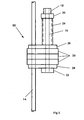
- FIGS 5-11 show a sealing device 50 that solves many of the problems of prior art seals.
- This sealing device 50 accommodates both the projection 14 and the tube 16 for injecting gas to conduct the test.
- the sealing device 50 includes upper and lower rigid plates 26, 28, and a plurality of flexible plates 30 sandwiched between the upper and lower rigid plates 26, 28.
- the details of the top rigid plate 26 are shown in Figures 8 and 9 , and the top rigid plate 26 is identical to the bottom rigid plate 28.
- the top rigid plate 26 defines a first opening 32, which extends to the perimeter of the plate 26 and receives the projection 14, and a second opening 34, which receives the injector tube 16.
- Each flexible plate 30 defines a first opening 36 that extends to the perimeter of the plate for receiving the projection 14, and a second opening 40, which receives the injector tube.
- the first openings 32, 36 of all the plates are vertically aligned to receive the projection 14, and the second openings 34, 40 of all the plates are vertically aligned to receive the injector tube 16, which has a connector 18 at its top end for connecting to the injection gas line.
- the slit portions 38 of the first openings 36 in the flexible plates 30, which extend to the perimeter of the flexible plates 30, are not aligned with the portions of the first openings 32 of the rigid plates 26, 28 that extend to the perimeters of the rigid plates.
- the first openings 32 of the rigid plates 26, 28 extend to the left, while the slit portions 38 of the first openings 36 of the flexible plates 30 extend to the front, so the first openings 32, 36 are not coextensive all the way to the perimeter, even though all the first openings 32, 36 extend to the perimeter of their respective plates.
- a mechanism for moving the upper and lower plates 26, 28 toward each other to compress the flexible plates 30 is mounted around the injector tube 16.
- This compression mechanism includes upper and lower nuts 20, 22 threaded onto the injector tube, and a compression sleeve 24 between the upper and lower nuts 20, 22.
- the injector tube 16 extends through the vertically aligned second openings 34, 40 in the upper and lower rigid plates and flexible plates 26, 28, 30, respectively.
- the rigid plates 26, 28 and the flexible plates 30 form a type of sandwich, with the rigid plates 26, 28 on the top and bottom, and the flexible plates 30 sandwiched between the rigid plates 26, 28.
- This particular embodiment uses three flexible plates 30, but the number may vary depending upon the application.
- Figure 7 shows the sealing device 50 after the upper nut 20 has been tightened downwardly against the compression sleeve 24, which, in turn, has pushed downwardly against the upper rigid plate 26.
- the lower rigid plate 28 cannot move downwardly, because it is stopped by the lower nut 22, so, as the upper rigid plate 26 moves downwardly toward the lower rigid plate 28, the flexible plates 30 are compressed in the vertical (axial) direction, causing them to expand radially outwardly to seal against the inner surface of the reactor tube. They also seal around the projection 14 and the injector tube 16.
- the injector tube 16, nuts 20, compression sleeve 24, rigid plates 26 and flexible plates 30 stay assembled together and are moved from one reactor tube to another.
- the nut 20 is loosened so the upper and lower rigid plates 26, 28 are separated a substantial distance apart.
- the slits 38 on the first openings 36 of the flexible plates 30 are pushed apart to form a passageway which allows the projection 14 to slide into those first openings 36.
- the device 50 is slid sideways and the flexible plates 30 are flexed, opening up the slits 38 (as indicated above) to position each flexible plate 30 onto the projection 14.
- the slits 38 in adjacent flexible plates 30 preferably extend in opposite directions (i.e. one flexible plate 30 is oriented in the forward direction as shown in Figure 11 and the next flexible plate 30 is flipped over so its slit 38 is extending in the rearward direction) so the slits 38 of adjacent flexible plates 30 are not aligned with each other.
- the projection 14 also enters into the first openings 32 of the rigid plates 26, 28. Once the projection 14 is extending through the first holes 36 in the flexible plates 30 and the first holes 32 of the upper and lower rigid plates 26, 28, the slits 38 of the flexible plates 30 are pushed back together again so all the flexible plates 30 are lying flat with the projection 14 received in their respective vertically aligned first openings 36.
- the upper and lower rigid plates 26, 28 are moved toward each other to compress the flexible plates 30.
- the upper nut 20 is tightened somewhat to bring the assembly together, and the assembly 50 is slid down the projection 14 into the reactor tube 10.
- the upper nut 20 is tightened more in order to compress the flexible plates 30, causing their outside diameters to expand and form the seal, and then the blowdown or test is conducted.
- a tray 200 (See Figures 24 and 25 ) is placed on top of the reactor tube 10, resting on the tube sheet 12, with the projection 14 fitting into a slot 210 in the tray 200.
- the tray 200 has a flat bottom with a raised rim 212 around its circumference.
- a plate 214 is hinged to the flat bottom by means of a hinge 216 to allow the plate 214 to be pivoted closed, thereby closing the remainder of the slot 210.
- the device 50 is assembled onto the thermocouple projection 14, with the tray 200 preventing any loose parts of the device 50 from falling into the reactor tube 10.
- the tray 200 is removed and the device 50 is inserted into the reactor tube and is used as described above.
- the upper nut 20 is loosened so the flexible plates 30 can return to their relaxed position, and the device 50 is then removed from the reactor tube 10 to be used in another location.
- the tray 200 may be used again while the device 50 is being disassembled, again to prevent any loose parts from falling into the reactor tube 10. While these drawings only show the connector 18 at the top of the device 50, it is understood that, in use, the connector 18 would be connected to a source of compressed gas, such as an injector from the hand held wand of the device shown in the referenced '706 and '404 patents.
- thermowell projection While this device 50 has been shown for use with a thermowell projection, it could be designed to accommodate other types of projections or obstructions, or, if the holes in the flexible plates 30 were eliminated, it could be used in a regular tube without a projection where a temporary seal is desired.
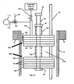
- Figure 12 shows another adaptation of the seal device described above.
- inner and outer seals including two sets 50A, 50B of sandwiched rigid plates 126, 128 and flexible plates 130, with a compression sleeve 124 between them.
- the additional tube 160 receives a regulated air flow which passes through an isolation valve164.
- a three-way valve 166 is used to allow air to pass out through a vent 166 to atmosphere or to a pressure sensor 170.
- the pressure sensor 170 is in communication with the tube 160 through a conduit 172, and through the valve 166, in order to measure the pressure in the void space or axial gap 174 between the outer and inner seals 50A, 50B.
- the supply valve 164 is opened, and pressurized air (or other gas) at roughly the same pressure as the air (or other gas) that will be supplied to the connector 18 is injected through the tube 160 into the void space 174, establishing a pressure within the void space 174. Then the supply valve 164 is closed, and the three-way valve 166 is positioned to allow communication between the void space or gap 174 and the pressure gauge 170.
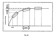
- a computer monitors the pressure at the pressure gauge 170 over a period of time and determines whether it meets the desired stability in terms of a certain number of pressure measurements within a desired range over a certain period of time, indicating that a good seal has been made, as shown in Figure 20 . Then the test or blowdown can be conducted. The pressure gauge 170 continues to be monitored as the test is being conducted to continue to ensure a good seal for the test. Once the test is completed, the three-way valve 166 is shifted to vent to atmosphere, the nut 20 is loosened, and the device is removed from the reactor tube 10.
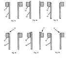
- Figures 13-19 show a variety of conditions that can be encountered at the top of the reactor tube 10, all of which can be accommodated by the seal device 50.
- the top of the reactor tube 10 is flush with the top of the tubesheet 12.
- the top of the reactor tube 10 projects above the top of the tubesheet 12.
- the top of the reactor tube 10 is recessed inside the top of the tubesheet 12.
- Figures 16 through 18 depict the same conditions as Figures 13 through 15 respectively, but with a weld bead 8 securing the reactor tube 10 to the tubesheet 12.
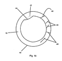
- FIG 19 is a top view of a reactor tube 10 depicting several quality issues which may arise and which affect the ability to make a good seal with prior art devices, such as with the rubber stopper shown in Figure 4 .
- the reactor tube 10 has an outer diameter 40 and an inner diameter 42.
- a weld repair 44 is shown which overhangs and reduces the inner diameter 42 of a portion of the tube 10, giving the inner surface of the tube an irregular, noncircular cross-section. Scratches and gouges 46 on top of the tube 10 may allow leaks to occur if a rubber stopper 2 is used (See Figure 4 ).
- Weld repair overlays 48 can result in high spots from the weld which can also allow leaks to occur with a prior art stopper, even when extreme force is used to push against the stopper. All of these conditions are reliably sealed with the seals described herein.
- Figures 21 and 23 are graphic displays that are generated by the tube testing or blowdown system, as generally explained in the referenced patents. However, the display of Figure 23 is specifically for the reactor tubes 10 that include thermowell projections 14.
- Figure 21 is a graphic representation of the tubesheet 12 of the reactor being tested, having the same shape and tube arrangement as the tubesheet 12. It indicates the numbering convention used, including first and last rows as well as first and last tubes in each row.
- the reactor tubes containing thermowells or thermocouples are typically identified by a different color from the regular tubes (black instead of white in this instance).
- the relevant information is displayed in the callout box as shown in Figure 23 .
- the message displayed in the callout box may include information such as the number of the thermocouple or other probe, the row number, the tube number (within that row), and the outage level and/or the pressure drop data, as well as an indication of the reliability of the seal based on the data from the pressure sensor 170.
- Figure 22 is another type of graphic display generated by the system, which shows the pressure drop value as measured with the aid of the device 50, correlated to certain levels of loading and indicating the target value and maximum and minimum values.
- FIG. 5A depicts another embodiment of a sealing device 50A made in accordance with the present invention. This is very similar to the sealing device 50 of Figure 5 , except that the injector tube 16 is threaded directly into the bottom rigid plate 28 instead of having a separate lower nut 22. Of course, instead of, or in addition to threading into this bottom rigid plate 28, the injector tube 16 could be welded or otherwise secured to the bottom rigid plate 28.
- the operation of the sealing device 50A is otherwise identical to that of the sealing device 50 described above.
Landscapes
- Chemical & Material Sciences (AREA)
- Chemical Kinetics & Catalysis (AREA)
- Organic Chemistry (AREA)
- Health & Medical Sciences (AREA)
- Clinical Laboratory Science (AREA)
- Monitoring And Testing Of Nuclear Reactors (AREA)
- Pipe Accessories (AREA)
- Examining Or Testing Airtightness (AREA)
- Closures For Containers (AREA)
Description
- This application claims priority from
U.S. Provisional Application Serial No. 60/887,855 filed February 2, 2007 - The present invention relates to a sealing arrangement.
U.S. Patents 6,725,706 and6,981,404 describe a system for blowing down and testing chemical reactor tubes. That system uses inflatable seals to seal against the inner wall of the reactor tube before injecting air into the tube and measuring the back pressure to determine whether the tube has been loaded properly with catalyst. In the course of using that system, two issues have arisen that are resolved here. The first is how to seal against a thermowell projection, which has an insert extending down into the tube for supporting thermocouples to measure temperature (or how to seal against other tubes, including ducts or ports, with similar types of obstructions). The second is how to know for certain that a good seal has been made so any measurement that is taken will be accurate. -
DE 298 03 091 A describes a device for sealed feed-through of at least one cable and/or pipe or the like through a passage configured in a wall, in particular for subsequent installation to a plurality of cables that have already been laid. An elastic sealing member can be placed in the passage. The sealing member has a plurality of recesses to receive the cables. A clamping device has two pressure bodies, which in a mounted state press from two sides onto the sealing member, so that it is pressed in a sealed manner onto the cables and the inner surface of the passage. The pressure bodies each have a plurality of recesses extending radially inwardly from the edge region to receive the cables, into which the cables can be laid from the outside. -
DE 19 00 716 A describes a sealing ring. A ring made of flexible material, preferably rubber, is pressed in a pressure-tight manner by means of a bilateral pressing effect, preferably produced by means of a screwing device, against an internal wall of a pipe and on the other side against a cable sheath. - According to the present invention, there is provided a seal as defined in appended
claim 1. -
-
Figure 1 is a section view through a vertical tube chemical reactor showing one of the thermowell vertical tubes; -
Figure 2 is a top view of a rubber stopper; -
Figure 3 is a front view of the rubber stopper ofFigure 2 ; -
Figure 4 is a section view showing the stopper being used to seal inside the reactor tube; -
Figure 5 is a front view of a sealing device made in accordance with the present invention; -
Figure 5A is a front view, similar to that ofFigure 5 , but for another embodiment of a sealing device made in accordance with the present invention; -
Figure 6 is a section view showing the sealing device ofFigure 5 after it has been inserted into the reactor tube; -
Figure 7 is the same view asFigure 6 but after the sealing device has been compressed in order to seal against the tube; -
Figure 8 is a front view of one of the rigid plates of the sealing device ofFigure 5 ; -
Figure 8A is a front view of an alternative rigid plate with an additional hole; -
Figure 9 is a top view of the rigid plate ofFigure 8 ; -
Figure 9A is a top view of the rigid plate ofFigure 8A ; -
Figure 10 is a front view of one of the flexible plates of the sealing device ofFigure 5 ; -
Figure 10A is a front view of an alternative flexible plate with an additional hole; -
Figure 11 is a top view of the flexible plate ofFigure 10 ; -
Figure 11A is a top view of the flexible plate ofFigure 10A ; -
Figure 12 is a section view through a vertical tube chemical reactor showing an alternative sealing device which includes inner and outer seals and a mechanism for ensuring that a good seal has been made; -
Figures 13-18 are section views through chemical reactor tubes showing various types of conditions that may be encountered in the top portion of the tube to be sealed; -
Figure 19 is a top view of a chemical reactor tube showing another condition that may be encountered in the top portion of the tube to be sealed; -
Figure 20 is a graph showing pressure measurements over a period of time; -
Figure 21 is a graphic representation of the reactor which is used to present test results and to indicate the location of special tubes, such as those with thermowells; -
Figure 22 is a graphic display that may be used to help load, analyze and test thermocouples; -
Figure 23 is a representation of the format that may be used to present the test results; -
Figure 24 is a top view of a tray for use with the device of the present invention; and -
Figure 25 is a side view of the tray ofFigure 24 . -
Figure 1 shows areactor tube 10 extending downwardly from atube sheet 12 of a chemical reactor. Thisparticular reactor tube 10 has athermowell projection 14 extending downwardly into thetube 10 and projecting out the top of thetube 10. Also shown in this view is aninjector tube 16, which is to be inserted temporarily into thereactor tube 10 to inject pressurized gas into thetube 10 for determining whether thetube 10 has been properly loaded with catalyst, or for blowing down the tube, as described in the 706 and '404 patents listed above. There may be as many as fifty or more thermowells to be tested on a reactor. The type of seal that is used in the 706 and '404 patents does not accommodate thethermowell projection 14. Thus, a different type of seal is used for those special reactor tubes that have thermowells or other similar projections orobstructions 14, which may be a probe to measure temperature, a probe to measure pressure, a sampling probe to sample gas, an injection probe to inject additives, or other types of projections. - The seal should be temporary as well as easy and quick to install and remove. The test typically is done at ambient temperature, but the
tube sheet 12 may be hotter than typical ambient temperature, sometimes as high as 54 degrees C (130 degrees F). The seal should be able to withstand the back pressure that is generated during the testing procedure without leaking. In tests that have been conducted so far, the back pressure has been as high as 206.8 kPa (30 psig), but it typically is 27.6-48.3 kPa (4-7 psig). Higher pressures can be accommodated by adding additionalflexible plates 30 andrigid plates 28/26 (SeeFigure 5 ) as described in more detail below. - Various sealing mechanisms have been tried in the past. For example,
Figures 2-4 show arubber stopper 2 being used. Therubber stopper 2 defines afirst opening 3 to accommodate theinjector tube 16, and asecond opening 4 to accommodate thethermowell projection 14. A slit 5 (SeeFigures 2 and 3 ) extends vertically the full length of thestopper 2, extending thesecond opening 4 to the perimeter of thestopper 2 so that thethermowell projection 14 may be inserted into thesecond opening 4 of thestopper 2 without having to remove thethermowell projection 14 from itsreactor tube 10. - As shown in
Figure 4 , thestopper 2 seals only at the top edge of thereactor tube 10. This type of seal tends to leak, as the back pressure tends to push the stopper upwardly, out of thetube 10. Other sealing methods, such as duct tape, visco-elastic materials and putty have been used as well. They tend to leave residue, are hard to use, portions may fall into the tube, and they do not seal reliably. -
Figures 5-11 show asealing device 50 that solves many of the problems of prior art seals. Thissealing device 50 accommodates both theprojection 14 and thetube 16 for injecting gas to conduct the test. - In this embodiment, the
sealing device 50 includes upper and lowerrigid plates flexible plates 30 sandwiched between the upper and lowerrigid plates rigid plate 26 are shown inFigures 8 and 9 , and the toprigid plate 26 is identical to the bottomrigid plate 28. The toprigid plate 26 defines afirst opening 32, which extends to the perimeter of theplate 26 and receives theprojection 14, and asecond opening 34, which receives theinjector tube 16. - The details of the
flexible plates 30 are shown inFigures 10 and 11 . Eachflexible plate 30 defines afirst opening 36 that extends to the perimeter of the plate for receiving theprojection 14, and asecond opening 40, which receives the injector tube. - The
first openings projection 14, and thesecond openings injector tube 16, which has aconnector 18 at its top end for connecting to the injection gas line. However, the slit portions 38 of thefirst openings 36 in theflexible plates 30, which extend to the perimeter of theflexible plates 30, are not aligned with the portions of thefirst openings 32 of therigid plates Figures 9 and 11 , thefirst openings 32 of therigid plates first openings 36 of theflexible plates 30 extend to the front, so thefirst openings first openings - As shown in
Figures 5-7 , a mechanism for moving the upper andlower plates flexible plates 30 is mounted around theinjector tube 16. This compression mechanism includes upper andlower nuts compression sleeve 24 between the upper andlower nuts injector tube 16 extends through the vertically alignedsecond openings flexible plates - As shown in the relaxed position in
Figure 6 , therigid plates flexible plates 30 form a type of sandwich, with therigid plates flexible plates 30 sandwiched between therigid plates flexible plates 30, but the number may vary depending upon the application. -
Figure 7 shows the sealingdevice 50 after theupper nut 20 has been tightened downwardly against thecompression sleeve 24, which, in turn, has pushed downwardly against the upperrigid plate 26. The lowerrigid plate 28 cannot move downwardly, because it is stopped by thelower nut 22, so, as the upperrigid plate 26 moves downwardly toward the lowerrigid plate 28, theflexible plates 30 are compressed in the vertical (axial) direction, causing them to expand radially outwardly to seal against the inner surface of the reactor tube. They also seal around theprojection 14 and theinjector tube 16. - In use, the
injector tube 16,nuts 20,compression sleeve 24,rigid plates 26 andflexible plates 30 stay assembled together and are moved from one reactor tube to another. In order to insert the sealingdevice 50 into areactor tube 10 with aprojection 14, thenut 20 is loosened so the upper and lowerrigid plates first openings 36 of theflexible plates 30 are pushed apart to form a passageway which allows theprojection 14 to slide into thosefirst openings 36. Then thedevice 50 is slid sideways and theflexible plates 30 are flexed, opening up the slits 38 (as indicated above) to position eachflexible plate 30 onto theprojection 14. The slits 38 in adjacentflexible plates 30 preferably extend in opposite directions (i.e. oneflexible plate 30 is oriented in the forward direction as shown inFigure 11 and the nextflexible plate 30 is flipped over so its slit 38 is extending in the rearward direction) so the slits 38 of adjacentflexible plates 30 are not aligned with each other. - As the
seal 50 is moved sideways, theprojection 14 also enters into thefirst openings 32 of therigid plates projection 14 is extending through thefirst holes 36 in theflexible plates 30 and thefirst holes 32 of the upper and lowerrigid plates flexible plates 30 are pushed back together again so all theflexible plates 30 are lying flat with theprojection 14 received in their respective vertically alignedfirst openings 36. - Then, the upper and lower
rigid plates flexible plates 30. First, theupper nut 20 is tightened somewhat to bring the assembly together, and theassembly 50 is slid down theprojection 14 into thereactor tube 10. Then theupper nut 20 is tightened more in order to compress theflexible plates 30, causing their outside diameters to expand and form the seal, and then the blowdown or test is conducted. - Before the
device 50 is used, a tray 200 (SeeFigures 24 and 25 ) is placed on top of thereactor tube 10, resting on thetube sheet 12, with theprojection 14 fitting into aslot 210 in thetray 200. Thetray 200 has a flat bottom with a raisedrim 212 around its circumference. Aplate 214 is hinged to the flat bottom by means of ahinge 216 to allow theplate 214 to be pivoted closed, thereby closing the remainder of theslot 210. Then thedevice 50 is assembled onto thethermocouple projection 14, with thetray 200 preventing any loose parts of thedevice 50 from falling into thereactor tube 10. Once thedevice 50 is assembled onto thethermocouple projection 14, thetray 200 is removed and thedevice 50 is inserted into the reactor tube and is used as described above. - Once the test has been conducted, or the
reactor tube 10 has been blown down, theupper nut 20 is loosened so theflexible plates 30 can return to their relaxed position, and thedevice 50 is then removed from thereactor tube 10 to be used in another location. Thetray 200 may be used again while thedevice 50 is being disassembled, again to prevent any loose parts from falling into thereactor tube 10. While these drawings only show theconnector 18 at the top of thedevice 50, it is understood that, in use, theconnector 18 would be connected to a source of compressed gas, such as an injector from the hand held wand of the device shown in the referenced '706 and '404 patents. - While this
device 50 has been shown for use with a thermowell projection, it could be designed to accommodate other types of projections or obstructions, or, if the holes in theflexible plates 30 were eliminated, it could be used in a regular tube without a projection where a temporary seal is desired. -
Figure 12 shows another adaptation of the seal device described above. In this case, there are inner and outer seals, including twosets rigid plates flexible plates 130, with acompression sleeve 124 between them. Also, in this embodiment, there is athird hole 134A (SeeFigure 9A ) in each of therigid plates Figure 11A ) in theflexible plates 130 in order to receive an additional tube 160 (SeeFigure 12 ) that serves both as an air supply tube and as a vent tube. Theadditional tube 160 receives a regulated air flow which passes through an isolation valve164. A three-way valve 166 is used to allow air to pass out through avent 166 to atmosphere or to apressure sensor 170. Thepressure sensor 170 is in communication with thetube 160 through aconduit 172, and through thevalve 166, in order to measure the pressure in the void space oraxial gap 174 between the outer andinner seals - Once the
seals reactor tube 10, thesupply valve 164 is opened, and pressurized air (or other gas) at roughly the same pressure as the air (or other gas) that will be supplied to theconnector 18 is injected through thetube 160 into thevoid space 174, establishing a pressure within thevoid space 174. Then thesupply valve 164 is closed, and the three-way valve 166 is positioned to allow communication between the void space orgap 174 and thepressure gauge 170. - A computer monitors the pressure at the
pressure gauge 170 over a period of time and determines whether it meets the desired stability in terms of a certain number of pressure measurements within a desired range over a certain period of time, indicating that a good seal has been made, as shown inFigure 20 . Then the test or blowdown can be conducted. Thepressure gauge 170 continues to be monitored as the test is being conducted to continue to ensure a good seal for the test. Once the test is completed, the three-way valve 166 is shifted to vent to atmosphere, thenut 20 is loosened, and the device is removed from thereactor tube 10. - While this arrangement uses gas at a pressure above ambient to see whether the pressure in the void space drops due to a leak, it would also be possible to use gas at a pressure below ambient and see whether the pressure in the void space rises due to a leak. Also, while this arrangement was developed for use with chemical reactor tubes, it may be used to check for leaks in other vessels or containments as well. If no other test or operation is to be conducted other than the leak test, then there may be only two probes extending through the outer seal, one for injecting the gas and one for measuring the pressure in the void space, and there may be no probe extending through the inner seal.
-
Figures 13-19 show a variety of conditions that can be encountered at the top of thereactor tube 10, all of which can be accommodated by theseal device 50. InFigure 13 , the top of thereactor tube 10 is flush with the top of thetubesheet 12. InFigure 14 , the top of thereactor tube 10 projects above the top of thetubesheet 12. InFigure 15 , the top of thereactor tube 10 is recessed inside the top of thetubesheet 12.Figures 16 through 18 depict the same conditions asFigures 13 through 15 respectively, but with aweld bead 8 securing thereactor tube 10 to thetubesheet 12. -
Figure 19 is a top view of areactor tube 10 depicting several quality issues which may arise and which affect the ability to make a good seal with prior art devices, such as with the rubber stopper shown inFigure 4 . Thereactor tube 10 has anouter diameter 40 and aninner diameter 42. Aweld repair 44 is shown which overhangs and reduces theinner diameter 42 of a portion of thetube 10, giving the inner surface of the tube an irregular, noncircular cross-section. Scratches and gouges 46 on top of thetube 10 may allow leaks to occur if arubber stopper 2 is used (SeeFigure 4 ). Weld repair overlays 48 can result in high spots from the weld which can also allow leaks to occur with a prior art stopper, even when extreme force is used to push against the stopper. All of these conditions are reliably sealed with the seals described herein. -
Figures 21 and23 are graphic displays that are generated by the tube testing or blowdown system, as generally explained in the referenced patents. However, the display ofFigure 23 is specifically for thereactor tubes 10 that includethermowell projections 14. -
Figure 21 is a graphic representation of thetubesheet 12 of the reactor being tested, having the same shape and tube arrangement as thetubesheet 12. It indicates the numbering convention used, including first and last rows as well as first and last tubes in each row. The reactor tubes containing thermowells or thermocouples are typically identified by a different color from the regular tubes (black instead of white in this instance). As the computer cursor is placed over the graphic representation of a particular tube, the relevant information is displayed in the callout box as shown inFigure 23 . The message displayed in the callout box may include information such as the number of the thermocouple or other probe, the row number, the tube number (within that row), and the outage level and/or the pressure drop data, as well as an indication of the reliability of the seal based on the data from thepressure sensor 170. -
Figure 22 is another type of graphic display generated by the system, which shows the pressure drop value as measured with the aid of thedevice 50, correlated to certain levels of loading and indicating the target value and maximum and minimum values. -
Figure 5A depicts another embodiment of asealing device 50A made in accordance with the present invention. This is very similar to the sealingdevice 50 ofFigure 5 , except that theinjector tube 16 is threaded directly into the bottomrigid plate 28 instead of having a separatelower nut 22. Of course, instead of, or in addition to threading into this bottomrigid plate 28, theinjector tube 16 could be welded or otherwise secured to the bottomrigid plate 28. The operation of thesealing device 50A is otherwise identical to that of the sealingdevice 50 described above. - While the terms "upper" and "lower" and "horizontal" are used herein, it should be understood that this terminology is intended only to describe the relative positions of parts, and the device could be used in other orientations. such as in the bottom tubesheet of the reactor, or in the end of a horizontal tube, for instance. Also, while the rigid plates and flexible plates shown here are circular, they would be shaped to conform to the shape of the tube (including a duct or conduit) against which the seal is intended to seal, which could be oval, square, or many other shapes.
Claims (7)
- A seal for a tube (10) having a projection (14) coming out of the tube (10), comprising:upper and lower rigid plates (26, 28), each having a perimeter and defining first (32) and second (34) openings, wherein said first openings (32) extend to the perimeter of their respective plates (26, 28);at least one flexible plate (30) having a perimeter and defining first (36) and second (40) openings, wherein said first opening (36) extends to the perimeter of the flexible plate (30), said flexible plate (30) being sandwiched between the upper and lower rigid plates (26, 28);wherein said first openings (32, 36) of said upper and lower rigid plates (26, 28) and of said flexible plate (30) are vertically aligned and said second openings (34, 40) of said upper and lower rigid plates (26, 28) and of said flexible plate (30) are vertically aligned; andwherein said upper and lower rigid plates (26, 28) have substantially the same diameter and said flexible plate (30) has a diameter that expands to be larger than the diameter of the upper and lower rigid plates (26, 28) when it is compressed between the upper and lower rigid plates (26, 28);wherein the seal further comprises compression means (20,22,24) extending through said second openings for moving the upper and lower rigid plates (26, 28) toward each other to compress the flexible plate (30); characterized in that:said compression means (20,22,24) includes an injector tube (16) extending through said second openings (34, 40).
- A seal for a tube having a projection coming out of the tube as recited in claim 1 wherein there is a plurality of said flexible plates (30) between said upper and lower rigid plates (26, 28) and wherein said compression means includes at least one nut (20, 22) threaded onto the injector tube.
- A seal for a tube as recited in claim 1, wherein each of said upper and lower rigid plates (26, 28) and said flexible plate (30) also defines a third opening (134A, 141), and said respective third openings (134A, 141) are vertically aligned.
- A seal for a tube as recited in claim 3, and further comprising a tube (160) received in said aligned third openings (134A, 141).
- A seal for a tube having a projection coming out of the tube as recited in claim 1, wherein said compression means further includes a compression sleeve (24) surrounding said injector tube above said upper rigid plate (26).
- A seal for a tube having a projection coming out of the tube as recited in claim 5, wherein said compression means further includes at least one nut (20) threaded onto the injector tube above said compression sleeve (24).
- A seal for a tube as recited in any preceding claim in combination with a chemical reactor tube (10) having a projection (14) wherein said upper and lower rigid plates (26, 28) and said flexible plate (30) are located inside the chemical reactor tube (10), with the projection (14) from the tube (10) extending through said first aligned openings (32, 36) and with said flexible plate (30) sealing against the inner surface of said chemical reactor tube (10) and sealing around the projection (14).
Applications Claiming Priority (2)
| Application Number | Priority Date | Filing Date | Title |
|---|---|---|---|
| US88785507P | 2007-02-02 | 2007-02-02 | |
| PCT/US2008/052392 WO2008097769A2 (en) | 2007-02-02 | 2008-01-30 | Seal for tube |
Publications (2)
| Publication Number | Publication Date |
|---|---|
| EP2109497A2 EP2109497A2 (en) | 2009-10-21 |
| EP2109497B1 true EP2109497B1 (en) | 2012-08-29 |
Family
ID=39471649
Family Applications (1)
| Application Number | Title | Priority Date | Filing Date |
|---|---|---|---|
| EP08728507A Not-in-force EP2109497B1 (en) | 2007-02-02 | 2008-01-30 | Seal for tube |
Country Status (6)
| Country | Link |
|---|---|
| US (1) | US7861875B2 (en) |
| EP (1) | EP2109497B1 (en) |
| JP (1) | JP5323723B2 (en) |
| KR (1) | KR101404377B1 (en) |
| MY (1) | MY153856A (en) |
| WO (1) | WO2008097769A2 (en) |
Families Citing this family (12)
| Publication number | Priority date | Publication date | Assignee | Title |
|---|---|---|---|---|
| US8752291B2 (en) | 2007-10-11 | 2014-06-17 | Extundo Incorporated | Method for marking tubes in a shell and tube heat exchanger |
| US8511249B1 (en) | 2009-09-23 | 2013-08-20 | Extundo Incorporated | Pointer arrangement for marking tubes in a shell and tube heat exchanger |
| US8562270B1 (en) | 2009-09-23 | 2013-10-22 | Extundo Incorporated | Loading arrangement including a dam for confining catalyst and other particles on the top tubesheet of a chemical reactor |
| US9149778B2 (en) | 2010-05-24 | 2015-10-06 | Extundo Incorporated | Device and method for dispensing catalyst pellets |
| US9138709B2 (en) | 2010-05-24 | 2015-09-22 | Extundo Incorporated | Device and method for dispensing pellets |
| KR20130077842A (en) | 2010-05-24 | 2013-07-09 | 엑스턴도 인코포레이티드 | Device for loading catalyst into a reactor vessel |
| JP5720985B2 (en) * | 2010-12-15 | 2015-05-20 | 株式会社Ihi | Piping penetration welding part vacuum box sealing method and piping penetration welding part vacuum box testing device |
| US20140238950A1 (en) * | 2011-09-30 | 2014-08-28 | Ge Heal Thcare Limited | Container connector |
| US20180038765A1 (en) * | 2016-08-07 | 2018-02-08 | Kevin P. Wheeler | Containment testing devices, methods, and systems |
| CN110726516A (en) * | 2019-11-12 | 2020-01-24 | 湖北伊克斯热交换系统有限公司 | Airtight detection frock |
| CN113286651B (en) * | 2019-12-16 | 2023-01-17 | 昭和电工株式会社 | Fixed-bed multi-tubular reactor for the manufacture of vinyl acetate |
| US12480085B1 (en) * | 2025-01-29 | 2025-11-25 | Mettler-Toledo Autochem, Inc. | Reactor sampling apparatus, system, and method |
Family Cites Families (12)
| Publication number | Priority date | Publication date | Assignee | Title |
|---|---|---|---|---|
| DE1900716A1 (en) | 1969-01-08 | 1970-08-13 | Maschb Hafenhuette Peter Lanci | Sealing ring |
| US3845787A (en) * | 1971-10-27 | 1974-11-05 | Lincoln Hall Research Co | Liquor supply for an automated liquor dispensing system |
| US3916960A (en) * | 1974-04-26 | 1975-11-04 | Browning Ferris Industries | Catalyst unloader apparatus and method |
| JPS6232583U (en) * | 1985-08-14 | 1987-02-26 | ||
| US4953728A (en) * | 1988-12-05 | 1990-09-04 | Meek John R | Tamper proof bottle |
| US5636757A (en) * | 1996-02-22 | 1997-06-10 | Porvaznik; Tom | Bottle stopper with integral remover |
| GB9623544D0 (en) * | 1996-11-12 | 1997-01-08 | Micromass Ltd | Sample vial and vial closure device for use in gas analysis and method of using the same |
| US5924585A (en) * | 1998-01-26 | 1999-07-20 | Vlsi Technology, Inc. | Connections and methods of restricting an opening |
| DE29803091U1 (en) | 1998-02-25 | 1998-04-30 | DOYMA GmbH & Co, 28876 Oyten | Device for the tight implementation of at least one cable and / or pipe or the like. through a breakthrough formed in a wall |
| US6694802B1 (en) * | 2000-09-22 | 2004-02-24 | Mathis P. Comardo | Delta P testing system for tube and shell type catalytic reactors |
| US6981404B2 (en) | 2001-03-16 | 2006-01-03 | Tubemaster, Inc | Device and method for use with chemical reactor tubes |
| ATE401122T1 (en) * | 2001-03-16 | 2008-08-15 | Tubemaster Inc | METHOD FOR MEASURING BACK PRESSURE IN CHEMICAL REACTION TUBES |
-
2008
- 2008-01-30 US US12/022,311 patent/US7861875B2/en active Active
- 2008-01-30 EP EP08728507A patent/EP2109497B1/en not_active Not-in-force
- 2008-01-30 WO PCT/US2008/052392 patent/WO2008097769A2/en not_active Ceased
- 2008-01-30 MY MYPI20092853A patent/MY153856A/en unknown
- 2008-01-30 KR KR1020097017220A patent/KR101404377B1/en active Active
- 2008-01-30 JP JP2009548404A patent/JP5323723B2/en not_active Expired - Fee Related
Also Published As
| Publication number | Publication date |
|---|---|
| JP2010517878A (en) | 2010-05-27 |
| WO2008097769A3 (en) | 2008-11-27 |
| US20080184779A1 (en) | 2008-08-07 |
| EP2109497A2 (en) | 2009-10-21 |
| US7861875B2 (en) | 2011-01-04 |
| KR20090115152A (en) | 2009-11-04 |
| MY153856A (en) | 2015-03-31 |
| JP5323723B2 (en) | 2013-10-23 |
| WO2008097769A2 (en) | 2008-08-14 |
| KR101404377B1 (en) | 2014-06-09 |
Similar Documents
| Publication | Publication Date | Title |
|---|---|---|
| US7861875B2 (en) | Seal for tube | |
| US5295760A (en) | Testable bulkhead | |
| US20070256478A1 (en) | Apparatus and method for measuring cavity leakage | |
| CN110828008B (en) | Parameter monitoring and sampling system of nuclear fuel irradiation examination device | |
| CN101271034A (en) | Gas meter leak tightness detecting method and device thereof | |
| US6523394B2 (en) | Leak test fixture | |
| KR101395739B1 (en) | Apparatus and method for detecting leakage of gas meter | |
| US20040173008A1 (en) | Device and method for blowing down and measuring the back pressure of chemical reactor tubes | |
| US7216530B2 (en) | Fluid containment element leak detection apparatus and method | |
| CN108801771A (en) | A kind of high pressure charge and discharge rubber lined hose strength test device | |
| CN109342412A (en) | A detection device that can detect multiple types of gases simultaneously | |
| CN119985278A (en) | A corrosion detection device for hydrogen storage container | |
| CN201096592Y (en) | Device for detecting sensor leakage | |
| NO326067B1 (en) | Apparatus for leak testing and / or pressure testing of a portion of a rudder as well as the method of using the same | |
| KR101187563B1 (en) | Fuel leak test device for wing fuel tank | |
| RU2238212C1 (en) | Connecting chamber for testing portlights | |
| EP0996853A1 (en) | Multi-sensor hydrostatic gauge for fuel storage tanks | |
| US20210063331A1 (en) | Dilatometer | |
| CN208596077U (en) | A kind of high pressure charge and discharge rubber lined hose strength test device | |
| KR200489626Y1 (en) | Piping connector and inspection device | |
| CN110726519A (en) | Special integrated testing machine for detecting internal and external pressure tightness of sounding pipe | |
| JPH07116420A (en) | Sealability inspection device of dust extractor | |
| CN220437689U (en) | Seal ring sealing performance testing device | |
| JP2006084263A (en) | Gas leak inspection device | |
| CN214845120U (en) | Zirconia probe testing device |
Legal Events
| Date | Code | Title | Description |
|---|---|---|---|
| PUAI | Public reference made under article 153(3) epc to a published international application that has entered the european phase |
Free format text: ORIGINAL CODE: 0009012 |
|
| 17P | Request for examination filed |
Effective date: 20090710 |
|
| AK | Designated contracting states |
Kind code of ref document: A2 Designated state(s): AT BE BG CH CY CZ DE DK EE ES FI FR GB GR HR HU IE IS IT LI LT LU LV MC MT NL NO PL PT RO SE SI SK TR |
|
| 17Q | First examination report despatched |
Effective date: 20100205 |
|
| DAX | Request for extension of the european patent (deleted) | ||
| GRAP | Despatch of communication of intention to grant a patent |
Free format text: ORIGINAL CODE: EPIDOSNIGR1 |
|
| GRAS | Grant fee paid |
Free format text: ORIGINAL CODE: EPIDOSNIGR3 |
|
| GRAA | (expected) grant |
Free format text: ORIGINAL CODE: 0009210 |
|
| AK | Designated contracting states |
Kind code of ref document: B1 Designated state(s): AT BE BG CH CY CZ DE DK EE ES FI FR GB GR HR HU IE IS IT LI LT LU LV MC MT NL NO PL PT RO SE SI SK TR |
|
| REG | Reference to a national code |
Ref country code: GB Ref legal event code: FG4D |
|
| REG | Reference to a national code |
Ref country code: CH Ref legal event code: EP |
|
| REG | Reference to a national code |
Ref country code: AT Ref legal event code: REF Ref document number: 572760 Country of ref document: AT Kind code of ref document: T Effective date: 20120915 |
|
| REG | Reference to a national code |
Ref country code: IE Ref legal event code: FG4D |
|
| REG | Reference to a national code |
Ref country code: DE Ref legal event code: R096 Ref document number: 602008018380 Country of ref document: DE Effective date: 20121025 |
|
| REG | Reference to a national code |
Ref country code: NL Ref legal event code: T3 |
|
| REG | Reference to a national code |
Ref country code: AT Ref legal event code: MK05 Ref document number: 572760 Country of ref document: AT Kind code of ref document: T Effective date: 20120829 |
|
| REG | Reference to a national code |
Ref country code: LT Ref legal event code: MG4D Effective date: 20120829 |
|
| PG25 | Lapsed in a contracting state [announced via postgrant information from national office to epo] |
Ref country code: HR Free format text: LAPSE BECAUSE OF FAILURE TO SUBMIT A TRANSLATION OF THE DESCRIPTION OR TO PAY THE FEE WITHIN THE PRESCRIBED TIME-LIMIT Effective date: 20120829 Ref country code: LT Free format text: LAPSE BECAUSE OF FAILURE TO SUBMIT A TRANSLATION OF THE DESCRIPTION OR TO PAY THE FEE WITHIN THE PRESCRIBED TIME-LIMIT Effective date: 20120829 Ref country code: FI Free format text: LAPSE BECAUSE OF FAILURE TO SUBMIT A TRANSLATION OF THE DESCRIPTION OR TO PAY THE FEE WITHIN THE PRESCRIBED TIME-LIMIT Effective date: 20120829 Ref country code: IS Free format text: LAPSE BECAUSE OF FAILURE TO SUBMIT A TRANSLATION OF THE DESCRIPTION OR TO PAY THE FEE WITHIN THE PRESCRIBED TIME-LIMIT Effective date: 20121229 Ref country code: NO Free format text: LAPSE BECAUSE OF FAILURE TO SUBMIT A TRANSLATION OF THE DESCRIPTION OR TO PAY THE FEE WITHIN THE PRESCRIBED TIME-LIMIT Effective date: 20121129 Ref country code: AT Free format text: LAPSE BECAUSE OF FAILURE TO SUBMIT A TRANSLATION OF THE DESCRIPTION OR TO PAY THE FEE WITHIN THE PRESCRIBED TIME-LIMIT Effective date: 20120829 |
|
| PG25 | Lapsed in a contracting state [announced via postgrant information from national office to epo] |
Ref country code: PT Free format text: LAPSE BECAUSE OF FAILURE TO SUBMIT A TRANSLATION OF THE DESCRIPTION OR TO PAY THE FEE WITHIN THE PRESCRIBED TIME-LIMIT Effective date: 20121231 Ref country code: SE Free format text: LAPSE BECAUSE OF FAILURE TO SUBMIT A TRANSLATION OF THE DESCRIPTION OR TO PAY THE FEE WITHIN THE PRESCRIBED TIME-LIMIT Effective date: 20120829 Ref country code: LV Free format text: LAPSE BECAUSE OF FAILURE TO SUBMIT A TRANSLATION OF THE DESCRIPTION OR TO PAY THE FEE WITHIN THE PRESCRIBED TIME-LIMIT Effective date: 20120829 Ref country code: GR Free format text: LAPSE BECAUSE OF FAILURE TO SUBMIT A TRANSLATION OF THE DESCRIPTION OR TO PAY THE FEE WITHIN THE PRESCRIBED TIME-LIMIT Effective date: 20121130 Ref country code: SI Free format text: LAPSE BECAUSE OF FAILURE TO SUBMIT A TRANSLATION OF THE DESCRIPTION OR TO PAY THE FEE WITHIN THE PRESCRIBED TIME-LIMIT Effective date: 20120829 |
|
| PG25 | Lapsed in a contracting state [announced via postgrant information from national office to epo] |
Ref country code: RO Free format text: LAPSE BECAUSE OF FAILURE TO SUBMIT A TRANSLATION OF THE DESCRIPTION OR TO PAY THE FEE WITHIN THE PRESCRIBED TIME-LIMIT Effective date: 20120829 Ref country code: EE Free format text: LAPSE BECAUSE OF FAILURE TO SUBMIT A TRANSLATION OF THE DESCRIPTION OR TO PAY THE FEE WITHIN THE PRESCRIBED TIME-LIMIT Effective date: 20120829 Ref country code: CZ Free format text: LAPSE BECAUSE OF FAILURE TO SUBMIT A TRANSLATION OF THE DESCRIPTION OR TO PAY THE FEE WITHIN THE PRESCRIBED TIME-LIMIT Effective date: 20120829 Ref country code: DK Free format text: LAPSE BECAUSE OF FAILURE TO SUBMIT A TRANSLATION OF THE DESCRIPTION OR TO PAY THE FEE WITHIN THE PRESCRIBED TIME-LIMIT Effective date: 20120829 |
|
| PG25 | Lapsed in a contracting state [announced via postgrant information from national office to epo] |
Ref country code: PL Free format text: LAPSE BECAUSE OF FAILURE TO SUBMIT A TRANSLATION OF THE DESCRIPTION OR TO PAY THE FEE WITHIN THE PRESCRIBED TIME-LIMIT Effective date: 20120829 Ref country code: IT Free format text: LAPSE BECAUSE OF FAILURE TO SUBMIT A TRANSLATION OF THE DESCRIPTION OR TO PAY THE FEE WITHIN THE PRESCRIBED TIME-LIMIT Effective date: 20120829 Ref country code: SK Free format text: LAPSE BECAUSE OF FAILURE TO SUBMIT A TRANSLATION OF THE DESCRIPTION OR TO PAY THE FEE WITHIN THE PRESCRIBED TIME-LIMIT Effective date: 20120829 Ref country code: CY Free format text: LAPSE BECAUSE OF FAILURE TO SUBMIT A TRANSLATION OF THE DESCRIPTION OR TO PAY THE FEE WITHIN THE PRESCRIBED TIME-LIMIT Effective date: 20120829 |
|
| PLBE | No opposition filed within time limit |
Free format text: ORIGINAL CODE: 0009261 |
|
| STAA | Information on the status of an ep patent application or granted ep patent |
Free format text: STATUS: NO OPPOSITION FILED WITHIN TIME LIMIT |
|
| PG25 | Lapsed in a contracting state [announced via postgrant information from national office to epo] |
Ref country code: BG Free format text: LAPSE BECAUSE OF FAILURE TO SUBMIT A TRANSLATION OF THE DESCRIPTION OR TO PAY THE FEE WITHIN THE PRESCRIBED TIME-LIMIT Effective date: 20121129 |
|
| 26N | No opposition filed |
Effective date: 20130530 |
|
| PG25 | Lapsed in a contracting state [announced via postgrant information from national office to epo] |
Ref country code: MC Free format text: LAPSE BECAUSE OF NON-PAYMENT OF DUE FEES Effective date: 20130131 |
|
| REG | Reference to a national code |
Ref country code: CH Ref legal event code: PL |
|
| GBPC | Gb: european patent ceased through non-payment of renewal fee |
Effective date: 20130130 |
|
| REG | Reference to a national code |
Ref country code: DE Ref legal event code: R097 Ref document number: 602008018380 Country of ref document: DE Effective date: 20130530 |
|
| REG | Reference to a national code |
Ref country code: IE Ref legal event code: MM4A |
|
| REG | Reference to a national code |
Ref country code: FR Ref legal event code: ST Effective date: 20130930 |
|
| PG25 | Lapsed in a contracting state [announced via postgrant information from national office to epo] |
Ref country code: ES Free format text: LAPSE BECAUSE OF FAILURE TO SUBMIT A TRANSLATION OF THE DESCRIPTION OR TO PAY THE FEE WITHIN THE PRESCRIBED TIME-LIMIT Effective date: 20121210 Ref country code: LI Free format text: LAPSE BECAUSE OF NON-PAYMENT OF DUE FEES Effective date: 20130131 Ref country code: CH Free format text: LAPSE BECAUSE OF NON-PAYMENT OF DUE FEES Effective date: 20130131 |
|
| PG25 | Lapsed in a contracting state [announced via postgrant information from national office to epo] |
Ref country code: FR Free format text: LAPSE BECAUSE OF NON-PAYMENT OF DUE FEES Effective date: 20130131 Ref country code: GB Free format text: LAPSE BECAUSE OF NON-PAYMENT OF DUE FEES Effective date: 20130130 |
|
| PG25 | Lapsed in a contracting state [announced via postgrant information from national office to epo] |
Ref country code: IE Free format text: LAPSE BECAUSE OF NON-PAYMENT OF DUE FEES Effective date: 20130130 |
|
| PGFP | Annual fee paid to national office [announced via postgrant information from national office to epo] |
Ref country code: BE Payment date: 20140114 Year of fee payment: 7 Ref country code: NL Payment date: 20140110 Year of fee payment: 7 Ref country code: DE Payment date: 20140122 Year of fee payment: 7 |
|
| PG25 | Lapsed in a contracting state [announced via postgrant information from national office to epo] |
Ref country code: MT Free format text: LAPSE BECAUSE OF FAILURE TO SUBMIT A TRANSLATION OF THE DESCRIPTION OR TO PAY THE FEE WITHIN THE PRESCRIBED TIME-LIMIT Effective date: 20120829 |
|
| PG25 | Lapsed in a contracting state [announced via postgrant information from national office to epo] |
Ref country code: BE Free format text: LAPSE BECAUSE OF NON-PAYMENT OF DUE FEES Effective date: 20150131 Ref country code: TR Free format text: LAPSE BECAUSE OF FAILURE TO SUBMIT A TRANSLATION OF THE DESCRIPTION OR TO PAY THE FEE WITHIN THE PRESCRIBED TIME-LIMIT Effective date: 20120829 |
|
| PG25 | Lapsed in a contracting state [announced via postgrant information from national office to epo] |
Ref country code: HU Free format text: LAPSE BECAUSE OF FAILURE TO SUBMIT A TRANSLATION OF THE DESCRIPTION OR TO PAY THE FEE WITHIN THE PRESCRIBED TIME-LIMIT; INVALID AB INITIO Effective date: 20080130 Ref country code: LU Free format text: LAPSE BECAUSE OF NON-PAYMENT OF DUE FEES Effective date: 20130130 |
|
| REG | Reference to a national code |
Ref country code: DE Ref legal event code: R119 Ref document number: 602008018380 Country of ref document: DE |
|
| REG | Reference to a national code |
Ref country code: NL Ref legal event code: V1 Effective date: 20150801 |
|
| PG25 | Lapsed in a contracting state [announced via postgrant information from national office to epo] |
Ref country code: NL Free format text: LAPSE BECAUSE OF NON-PAYMENT OF DUE FEES Effective date: 20150801 |
|
| PG25 | Lapsed in a contracting state [announced via postgrant information from national office to epo] |
Ref country code: DE Free format text: LAPSE BECAUSE OF NON-PAYMENT OF DUE FEES Effective date: 20150801 |