EP2108972B1 - Method for detecting a battery condition - Google Patents
Method for detecting a battery condition Download PDFInfo
- Publication number
- EP2108972B1 EP2108972B1 EP09157720.5A EP09157720A EP2108972B1 EP 2108972 B1 EP2108972 B1 EP 2108972B1 EP 09157720 A EP09157720 A EP 09157720A EP 2108972 B1 EP2108972 B1 EP 2108972B1
- Authority
- EP
- European Patent Office
- Prior art keywords
- battery
- charge
- soc
- ocv
- reaction speed
- Prior art date
- Legal status (The legal status is an assumption and is not a legal conclusion. Google has not performed a legal analysis and makes no representation as to the accuracy of the status listed.)
- Active
Links
Images





Classifications
-
- G—PHYSICS
- G01—MEASURING; TESTING
- G01R—MEASURING ELECTRIC VARIABLES; MEASURING MAGNETIC VARIABLES
- G01R31/00—Arrangements for testing electric properties; Arrangements for locating electric faults; Arrangements for electrical testing characterised by what is being tested not provided for elsewhere
- G01R31/36—Arrangements for testing, measuring or monitoring the electrical condition of accumulators or electric batteries, e.g. capacity or state of charge [SoC]
- G01R31/3644—Constructional arrangements
- G01R31/3648—Constructional arrangements comprising digital calculation means, e.g. for performing an algorithm
-
- G—PHYSICS
- G01—MEASURING; TESTING
- G01R—MEASURING ELECTRIC VARIABLES; MEASURING MAGNETIC VARIABLES
- G01R31/00—Arrangements for testing electric properties; Arrangements for locating electric faults; Arrangements for electrical testing characterised by what is being tested not provided for elsewhere
- G01R31/36—Arrangements for testing, measuring or monitoring the electrical condition of accumulators or electric batteries, e.g. capacity or state of charge [SoC]
- G01R31/382—Arrangements for monitoring battery or accumulator variables, e.g. SoC
-
- G—PHYSICS
- G01—MEASURING; TESTING
- G01R—MEASURING ELECTRIC VARIABLES; MEASURING MAGNETIC VARIABLES
- G01R31/00—Arrangements for testing electric properties; Arrangements for locating electric faults; Arrangements for electrical testing characterised by what is being tested not provided for elsewhere
- G01R31/36—Arrangements for testing, measuring or monitoring the electrical condition of accumulators or electric batteries, e.g. capacity or state of charge [SoC]
- G01R31/382—Arrangements for monitoring battery or accumulator variables, e.g. SoC
- G01R31/3842—Arrangements for monitoring battery or accumulator variables, e.g. SoC combining voltage and current measurements
-
- G—PHYSICS
- G01—MEASURING; TESTING
- G01R—MEASURING ELECTRIC VARIABLES; MEASURING MAGNETIC VARIABLES
- G01R31/00—Arrangements for testing electric properties; Arrangements for locating electric faults; Arrangements for electrical testing characterised by what is being tested not provided for elsewhere
- G01R31/36—Arrangements for testing, measuring or monitoring the electrical condition of accumulators or electric batteries, e.g. capacity or state of charge [SoC]
- G01R31/385—Arrangements for measuring battery or accumulator variables
- G01R31/387—Determining ampere-hour charge capacity or SoC
-
- G—PHYSICS
- G01—MEASURING; TESTING
- G01R—MEASURING ELECTRIC VARIABLES; MEASURING MAGNETIC VARIABLES
- G01R31/00—Arrangements for testing electric properties; Arrangements for locating electric faults; Arrangements for electrical testing characterised by what is being tested not provided for elsewhere
- G01R31/36—Arrangements for testing, measuring or monitoring the electrical condition of accumulators or electric batteries, e.g. capacity or state of charge [SoC]
- G01R31/385—Arrangements for measuring battery or accumulator variables
- G01R31/387—Determining ampere-hour charge capacity or SoC
- G01R31/388—Determining ampere-hour charge capacity or SoC involving voltage measurements
-
- G—PHYSICS
- G01—MEASURING; TESTING
- G01R—MEASURING ELECTRIC VARIABLES; MEASURING MAGNETIC VARIABLES
- G01R31/00—Arrangements for testing electric properties; Arrangements for locating electric faults; Arrangements for electrical testing characterised by what is being tested not provided for elsewhere
- G01R31/36—Arrangements for testing, measuring or monitoring the electrical condition of accumulators or electric batteries, e.g. capacity or state of charge [SoC]
- G01R31/382—Arrangements for monitoring battery or accumulator variables, e.g. SoC
- G01R31/3835—Arrangements for monitoring battery or accumulator variables, e.g. SoC involving only voltage measurements
-
- G—PHYSICS
- G01—MEASURING; TESTING
- G01R—MEASURING ELECTRIC VARIABLES; MEASURING MAGNETIC VARIABLES
- G01R31/00—Arrangements for testing electric properties; Arrangements for locating electric faults; Arrangements for electrical testing characterised by what is being tested not provided for elsewhere
- G01R31/36—Arrangements for testing, measuring or monitoring the electrical condition of accumulators or electric batteries, e.g. capacity or state of charge [SoC]
- G01R31/392—Determining battery ageing or deterioration, e.g. state of health
Definitions
- the present invention relates to a battery residual capacity detecting method and a battery residual capacity detecting apparatus.
- FIGs. 13 and 14 are graphs showing examples of temporal change of the OCV when the SOC and temperature of the battery are constant.
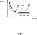
- FIG. 13 shows that it takes a time until when the OCV (reference numeral 82) is stabilized to a constant value even if the SOC is constant. While FIG. 14 shows changes of the OCVs (reference numerals 83, 84, 85) of batteries whose states of health (SOH) are different, it indicates that the OCVs do not converge to the identical OCV if the SOHs are different even if the SOC and temperature are adjusted so as to fall under the same condition and even if the latest discharge/charge conditions are kept same.
- the influence of the SOH is not reflected in finding the SOC from the OCV by using the state detecting method just by utilizing the latest discharge/charge history. Then, there is a problem that accuracy of state detection drops if the SOC is found from the OVC without reflecting the battery depletion condition.
- Patent Document 1 is known as one exemplary prior art.
- the document 1 uses transient response corresponding to discharge/charge history to compensate the OCV as a method for detecting the OCV and SOC of a secondary battery.
- the document 1 also refers to that the transient response changes corresponding to discharge/charge time and to a resistant component, a polarization component corresponding to internal reaction of the battery and diffusion speed of electrolytic solution.
- EP 1 887 370 A1 discloses a battery remaining electrical charge/remaining capacity estimating method which makes it possible to obtain a convergence value of a battery open circuit voltage.
- EP 1 324 062 A2 discloses a method for estimating a battery state by monitoring a temperature, the SOC and a deterioration of the battery.
- Patent Document 1 Japanese Patent Application Publication No. 2005-106615
- the present invention aims at providing a battery state detecting method for detecting states of a battery by evaluating depletion caused by reaction processes whose speed is different.
- the battery state detecting method of the invention is disclosed in claim 1.
- the invention thus provides the battery state detecting method for detecting the state by evaluating the depletion caused by the reaction processes whose speeds are different, so that it becomes possible to detect the state accurately.
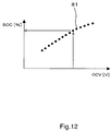
- the battery state detecting method of the invention evaluates SOH (state of health) which is an index of depletion level of the battery corresponding to reaction speed of the battery and evaluates SOC by using the SOH. Because the SOC has the relationship of one-to-one with the open circuit voltage (OCV) as shown in FIG. 12 , the SOC can be found by finding the OCV. However, the relationship of FIG. 12 holds when the state of the battery is stable and the OCV after discharge/charge changes as shown in FIG. 13 . Due to that, it is necessary to evaluate the SOC by using the OCV when the battery is fully stabilized after discharging/charging electricity.
- SOH state of health
- OCV open circuit voltage
- the OCV after discharge/charge changes by the SOH as shown in FIG. 14
- the OCV during the stable period also changes by the SOH.
- the transient change of the battery after discharge/charge is affected by the reaction processes whose reaction speed is fast such as ion generating and annihilating reaction and whose reaction speed is slow such as those caused by the move of the electrolytic solution.
- the battery state detecting method of the invention evaluates a variation of the SOH per reaction speed and compensates the OCV by using this SOH.
- lim described above indicates that the elapsed time t is infinitized with respect to a battery voltage (OCV) measured value V mes (t) after the elapse of time t from the discharge/charge.
- OCVs in the above equation also shows that it may be changed by the SOC, SOH and temperature T of the battery. While V mes (t) is also changed by the SOC, SOH and T of the battery during measurement, the equation (2) is expressed only by the time t when it is measured.
- the elapsed time from the stop of the discharge/charge may be a value other than 20 hours depending on types of the battery.
- ⁇ V(t) This change of voltage ⁇ V(t) has been handled while including all transient changes by using a term "polarization" in the conventional definition of electrical-chemistry.
- ⁇ V(t) is a change in voltage caused by a relaxation process until approaching to the stable OCV, it is affected by the following factors of change in voltage.
- the factors of the change in voltage include a condition of the polar plate, ion concentration in the vicinity of the polar plate, their solid-phase reaction and solid-liquid reaction and moves of ions with deposition, convection and diffusion of the electrolytic solution.
- ⁇ V(t) may be considered to be caused by integrating the relaxation processes whose reaction speeds are different.
- ⁇ V(t) may be represented by using a function F(t) composed of m polynomial expressions corresponding to the difference of the reaction speeds.
- each term fi(t) (relaxation function per reaction speed) represents a contribution to the change in voltage in each relaxation process intrinsic to the battery and each depends on the state of health SOH, the state of charge (ion concentration) SOC and the temperature T of the battery.
- the state detecting system has reference data therein in advance before it is connected with the battery.
- F(t) and each term fi(t) of the equation (5) representing the OCV variation ⁇ V(t) after the end of n-th discharge/charge after connecting the battery with the state detecting system and setting the initial values will be represented as F n (t) and fi n (t), respectively.
- fi ref (t), SOC ref , and SOHi ref are values in the initial state set in advance (unused state for example) and g(T) is a function indicating temperature dependency.
- SOH n SOH 1 n , SOH 2 n , ⁇ , SOHm n
- the equation (8') is one example in which the relationship of SOH1 through SOHm shown in the equation (8) is represented in a form of sum.
- the total of SOHi n is not limited to the form of the equation (8') in which
- the measurement of the relaxation speed of F n (t) can be carried out under the condition in which the discharge/charge of the battery is stopped. It is possible to use SOC n-1 for calculation of the relaxation function of F n (t) when operations are always carried out only with discharge/charge which is less than a threshold value.
- fi n (t) is updated by the following equation by using the SOHi n calculated by the equation (7) to calculate SOCi n .
- fi n t fi ref t SOC i n ⁇ 1 / SOC ref SOHi n / SOHi ref g T
- OCV 20 hr V mes t ⁇ ⁇ fi ref t SOC n ⁇ 1 / SOC ref SOHi n ⁇ 1 / SOHi ref g T
- FIGs. 1 through 7 are flowcharts showing flows of processes of the battery state detecting method of the embodiment.
- a state detector (02) comprises a means (20) for measuring temperature of the battery (01), a means (21) for measuring voltage of the battery (01), a means (22) for measuring current of the battery (01), a memory area (RAM) (23) for temporarily recording measured values measured by the respective measuring means (20 through 22), a stationary memory area (24) for storing reference data in advance, a processor (25) for detecting and judging the state based on the data stored in the RAM (23) and the ROM (24), a means (26) for outputting a judgment result to the outside, a means (27) capable of inputting information from an in-vehicle information controller (03) and a timer (28) capable of counting time.
- FIG. 2 shows one exemplary method for judging that the battery (01) has stopped to discharge/charge. This is a case when it is judged that the vehicle is parking or stopping from the information of the in-vehicle information controller (03) or when information on connect and disconnect of the battery (01) and the state detector (02) is inputted for example. Or, this is a case when a current value measured by the current measuring means (22) provided in the state detector (02) becomes a judgment threshold value or less recorded in the stationary memory area (24). The judgment may be made only by the in-vehicle information inputting means (27) or only the judgment of the current threshold value or by freely combining them (the part up to now is referred to as a threshold value judgment means).
- n 0 (times)
- n times a number of times of judgment when the state is judged that the discharge/charge is stopped by the threshold value judgment means in FIG. 2
- the counter value of the timer is confirmed with predetermined confirmation timing.
- the timer count (t_count) exceeds its measured timing value at the predetermined measuring timing
- the current measuring means (22) measures a voltage value V mes of the battery (01).
- V _ mes t t
- V t _ count
- V_mes(t) - OCV 20hr_ temp is stored as ⁇ V(t)_temp (see the equation (4), the acquisition of V_mes(t)).
- FIG. 4 shows a flow of a method for calculating OCV 20hr _temp.
- SOC and SOH in starting to calculate the n-th state, the previous calculated values SOC n-1 and SOH n-1 are used.
- Measured value T T_n obtained from the temperature measuring means (20) is used as the temperature of the battery at the present time.
- the relaxation function per reaction speed fi n (t) is optimized with respect to the data expressed by ⁇ V(t)_temp.
- Equation (5) is assumed to be composed of the following four terms hereinafter:
- FIGs. 6 and 7 illustrate a method for obtaining F n (t) from ⁇ V(t)_temp corresponding to an elapsed time from the timer count.
- Each coefficient is defined so that the functions shown in the equations (10-1 through 10-4) are dominant respectively to the four reference times (10s, 1000s, 36000s, 72000s) as a fitting function in that interval.
- the exemplified reference times (10s, 1000s, 36000s, 72000s) can be determined corresponding to a time constant based on the relaxation speed of the reaction speed within the battery.
- the reference time can be also changed not only by the relaxation speed within the battery but also by the accuracy required to the sensors and timing corresponding to traveling and resting conditions of an actual car.
- the determination method of the reference time it is possible to use a timer within the sensor, to use time of in-vehicle information, typified by car navigation, obtained from the in-vehicle information inputting means or to use their combination.
- FIG. 6 illustrates a method for obtaining F n (t) from ⁇ V(t)_temp when the elapsed time of the timer count is shorter than 20 hours.
- F n (t) is calculated by the following equation based on the data after finishing the previous discharge/charge F n-1 (t):
- F n t ffast 1 n-1 t + ffast 2 n-1 t + fslow 1 n-1 t + fslow 2 n ⁇ 1 t
- F n (t) is calculated by the following equation based on the data after finishing the previous discharge/charge F n-1 (t) and the latest data:
- F n t ffast 1 n t + ffast 2 n-1 t + fslow 1 n-1 t + fslow 2 n ⁇ 1 t
- F n (t) is calculated by the following equation based on the data after finishing the previous discharge/charge F n-1 (t) and the latest data:
- F n t ffast 1 n t + ffast 2 n t + fslow 1 n-1 t + fslow 2 n ⁇ 1 t
- F n (t) is calculated by the following equation based on the data after finishing the previous discharge/charge F n-1 (t) and the latest data:
- F n t ffast 1 n t + ffast 2 n t + fslow 1 n t + fslow 2 n ⁇ 1 t
- F n (t) is calculated by the following equation by not obtaining ⁇ V(t)_n from F n (20 hr) but by replacing with the equation (14-2):
- F n t ffast 1 n t + ffast 2 n t + fslow 1 n t + fslow 2 n t
- SOHi n is calculated by using fi(t) calculated in the flows in FIGs. 6 and 7 and stored in the temporary memory area (23) and reference data fi ref (t) and SOHi ref recorded in the stationary memory area (24) in advance.
- the comparison judging means compares SOC n and SOH n with the predetermined threshold values set in advance and judges that the battery is in the depletion state when SOC n is less than the threshold value or when SOH n is more than the threshold value. It is noted that the relationship between the magnitudes of SOH and the depletion level of the battery is reversed depending on system design. In such a case, it is needless to say that it is judged that the battery is in the depletion state when SOH n is less than the predetermined threshold value.
- FIG. 9 shows one example of changes of each terms when the relaxation function F(t) is expressed as the equation (10) as one embodiment of optimization of the relaxation function F(t) in the battery state detecting method of the embodiment.
- the reference numerals 51 through 54 indicate the changes of each term (Ffast1(t), Ffast2(t), Fslow1(t), Fslow2(t)) in the equation (10), respectively. Still more, the reference numeral 50 indicates a true value and the reference numeral 55 indicates a value of F(t) calculated from the equation (10). This indicates that it becomes possible to estimate ⁇ V(t) in high precision by using F(t) of the embodiment.
- SOH1 n after the n-th discharge/charge will be calculated by the following equation by defining a degree of stratification of the slow reaction speed (diffusion of the electrolytic solution and others) as SOH1 in the equation (7):
- SOH 1 n fslow n t / fslow ref t *
- SOH 1 ref fslow 1 n t + fslow 2 n t / fslow 1 ref t + fslow 2 ref t * SOH 1 ref
- fi n (t), fi ref (t) in the equation (7) is calculated further from the sums of two terms (fslow1 n (t) + fslow2 n (t)) and (fslow1 ref (t) + fslow2 ref (t)).
- SOH 1 50 fslow 1 50 5 hr + fslow 2 50 5 hr / fslow 1 20 5 hr + fslow 2 20 5 hr * SOH 1 20
- SOH 1 100 fslow 1 100 5 hr + fslow 2 100 5 hr / fslow 1 20 5 hr + fslow 2 20 5 hr * SOH 1 20
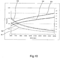
- FIG. 10 shows fslow n (t) /fslow 20 (t) calculated from the measured data.
- the reference numerals 61, 62 and 63 represent fslow 20 (t), fslow 50 (t) and fslow 100 (t), respectively and the reference numerals 64 and 65 represent fslow 50 (t) / fslow 20 (t) and fslow 100 (t) / fslow 20 (t), respectively.
- OCV 20 hr 20 12.896 V
- OCV 20 hr 50 13.032 V
- OCV 20 hr 100 13.036 V
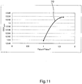
- FIG. 11 shows a relationship between fslow n (t)/fslow 20 (t) and OCV 20hr 20 .
- the result shown in FIG. 11 can be used in a stable OCV estimating equation for estimating OCV 20hr of the same type of battery.
- the invention can provide the battery state detecting method for detecting the state by evaluating the depletion caused by the reaction processes whose speeds are different. It becomes possible to accurately detect the residual capacity SOC by detecting the depletion level SOH of the battery. Thereby, it becomes possible to assure stable operation of the electric devices and to promote prediction of risk, thus having an effect of keeping safe operation of the vehicle.
- the invention also provides an effect of reducing an environmental burden by improving precision of the idling stop function.
Landscapes
- Physics & Mathematics (AREA)
- General Physics & Mathematics (AREA)
- Secondary Cells (AREA)
Description
- The present invention relates to a battery residual capacity detecting method and a battery residual capacity detecting apparatus.
- Since a vehicle has come to employ many electric devices for travelling lately, an importance of an in-vehicle power source is increasing more and more. Needs on the in-vehicle power source have been limited to perform such functions of starting an engine, operating an air-conditioner and lighting lamps in the past 20 to 30 years. In contrary to that, bi-wiring has spread and even parts of a safety system typified by an electronic parking brake (EPB) have come to be controlled by electricity. Still more, as a measure for improving gas mileage in an effort of saving energy and controlling emission of CO2, it is demanded to provide an idling stop function in stopping for a short period of time at an intersection and the like and to assure its restarting capability. Thus, a variety of functions is demanded on the power source and the battery and corresponding to that, it is desired to improve battery state detecting accuracy.
- In such a circumstance, it is an important technology to accurately detect a residual capacity (SOC: state of charge) of the battery in particular for safe and comfortable driving of the vehicle and for realizing an automobile society in which an environment is taken into account, because it is linked with stable operations of the electric devices such as the EPB.
- Under a battery stable condition, open circuit voltage (OCV) and the SOC thereof have a relationship of correspondence of one-to-one in general (a
reference numeral 81 inFIG. 12 ). However, after discharging and charging electricity, the battery is affected respectively by ion generating and annihilating reactions on a surface of a polar plate due to electro-chemical reactions and by moves of ions due to diffusion and convection of electrolytic solution. Therefore, it takes a time, e.g., around 20 hours, to converge to the stable OCV and the OCV does not correspond one-to-one with the SOC when there is such temporal change.FIGs. 13 and14 are graphs showing examples of temporal change of the OCV when the SOC and temperature of the battery are constant.FIG. 13 shows that it takes a time until when the OCV (reference numeral 82) is stabilized to a constant value even if the SOC is constant. WhileFIG. 14 shows changes of the OCVs (reference numerals - As described above, the influence of the SOH is not reflected in finding the SOC from the OCV by using the state detecting method just by utilizing the latest discharge/charge history. Then, there is a problem that accuracy of state detection drops if the SOC is found from the OVC without reflecting the battery depletion condition.
-
Patent Document 1 is known as one exemplary prior art. Thedocument 1 uses transient response corresponding to discharge/charge history to compensate the OCV as a method for detecting the OCV and SOC of a secondary battery. Thedocument 1 also refers to that the transient response changes corresponding to discharge/charge time and to a resistant component, a polarization component corresponding to internal reaction of the battery and diffusion speed of electrolytic solution.EP 1 887 370 A1EP 1 324 062 A2 - [Patent Document 1] Japanese Patent Application Publication No.
2005-106615 - According to the detection method described in
Patent Document 1, it is possible to find depletion corresponding to a fast reaction speed within the battery by measuring a short-period transient response by discharging and charging for a short period of time. However, it is unable to measure a long-term transient response, so that it is unable to detect depletion caused by slow reaction speed. Although it is necessary to discharge and charge for a long period of time to measure the long-term transient response, the SOC changes as the discharge/charge time becomes longer and hence the short-term transient response thereafter also changes. Thus, it is unable to detect the depletion corresponding to the different reaction speeds within the battery and to detect the states of the battery such as the residual capacity by the detecting method described inPatent Document 1. - Not only the ion generating and annihilating reactions (fast reaction speed) caused in the vicinity of the polar plate but also ion diffusion speed within the electrolytic solution (slow reaction speed) affects in a series of reaction processes called an electrical-chemical reaction within the battery. The reaction processes whose speed are different significantly affect the accuracy of the state detection as a factor of error in such reaction system.
- Accordingly, in order to solve those problems, the present invention aims at providing a battery state detecting method for detecting states of a battery by evaluating depletion caused by reaction processes whose speed is different.
- The battery state detecting method of the invention is disclosed in
claim 1. - Claims 2-10 describe additional features of the method of
claim 1. - The invention thus provides the battery state detecting method for detecting the state by evaluating the depletion caused by the reaction processes whose speeds are different, so that it becomes possible to detect the state accurately.
- A battery state detecting method of a preferred embodiment of the invention will be explained in detail with reference to the drawings. It is noted that each component having the same function will be denoted by the same reference numeral to simplify the drawings and their explanation.
- The battery state detecting method of the invention evaluates SOH (state of health) which is an index of depletion level of the battery corresponding to reaction speed of the battery and evaluates SOC by using the SOH. Because the SOC has the relationship of one-to-one with the open circuit voltage (OCV) as shown in
FIG. 12 , the SOC can be found by finding the OCV. However, the relationship ofFIG. 12 holds when the state of the battery is stable and the OCV after discharge/charge changes as shown inFIG. 13 . Due to that, it is necessary to evaluate the SOC by using the OCV when the battery is fully stabilized after discharging/charging electricity. - Still more, because the OCV after discharge/charge changes by the SOH as shown in
FIG. 14 , the OCV during the stable period also changes by the SOH. Still more, the transient change of the battery after discharge/charge is affected by the reaction processes whose reaction speed is fast such as ion generating and annihilating reaction and whose reaction speed is slow such as those caused by the move of the electrolytic solution. - Then, in order to be able to accurately evaluate the SOC by evaluating the influence of the slow reaction speed even when an elapsed time after discharge/charge is short, the battery state detecting method of the invention evaluates a variation of the SOH per reaction speed and compensates the OCV by using this SOH.
- One embodiment of the battery state detecting method of the invention will be explained below.
- At first, the OCV during the stable time after fully elapsing a time since discharge/charge will be expressed as OCVs and the relationship of one-to-one of the SOC and the OCVs shown in
FIG. 12 will be expressed by the following equation:
- Here, lim described above indicates that the elapsed time t is infinitized with respect to a battery voltage (OCV) measured value Vmes(t) after the elapse of time t from the discharge/charge. The OCVs in the above equation also shows that it may be changed by the SOC, SOH and temperature T of the battery. While Vmes(t) is also changed by the SOC, SOH and T of the battery during measurement, the equation (2) is expressed only by the time t when it is measured.
- In a case of a liquid-type lead battery, the temporal change of Vmes(t) per hour when 20 hours has elapsed becomes as fully small as 10 mV and an error with respect to magnitude of the OCV (about 12. 9V) becomes 0.1 % or less. Then, Vmes(t) when 20 hours has elapsed since the battery has stopped to discharge/charge is expressed as OCV20hr in the following equation and it is used for the OCVs:

- It is noted that the elapsed time from the stop of the discharge/charge may be a value other than 20 hours depending on types of the battery.
- When a variation of the voltage measured value Vmes(t) after stopping the discharge/charge from the stable OCV, i.e., an OCV variation, is expressed as ΔV(t), it can be expressed as follows:

- This change of voltage ΔV(t) has been handled while including all transient changes by using a term "polarization" in the conventional definition of electrical-chemistry. However, because ΔV(t) is a change in voltage caused by a relaxation process until approaching to the stable OCV, it is affected by the following factors of change in voltage. The factors of the change in voltage include a condition of the polar plate, ion concentration in the vicinity of the polar plate, their solid-phase reaction and solid-liquid reaction and moves of ions with deposition, convection and diffusion of the electrolytic solution. ΔV(t) may be considered to be caused by integrating the relaxation processes whose reaction speeds are different.
- ΔV(t) may be represented by using a function F(t) composed of m polynomial expressions corresponding to the difference of the reaction speeds.

- The state detecting system has reference data therein in advance before it is connected with the battery. Initial states corresponding to the battery to be connected will be represented as SOC0=SOCref(0), SOHi0= SOHiref(0) and OCV20hr 0 = OCV20hr ref(0). Each reference data is used as the initial value in the initial state in which the battery is connected with the state detecting system as n = 0-th measurement. F(t) and each term fi(t) of the equation (5) representing the OCV variation ΔV(t) after the end of n-th discharge/charge after connecting the battery with the state detecting system and setting the initial values will be represented as Fn(t) and fin(t), respectively. At this time, fin(t) may be calculated by the following equation from the SOC and SOH corresponding to the i-th reaction speed (represented as SOCn and SOHin, respectively):

- Here, firef(t), SOCref, and SOHiref are values in the initial state set in advance (unused state for example) and g(T) is a function indicating temperature dependency.
- When the temperature T and the SOC are constant regardless of the time in the equation (6), the SOHin can be calculated from the following equation:

- Accordingly, it is possible to obtain SOHin by using fin(t) obtained from the equation (6).
- From the equation (7), the overall SOHn to which SOHin caused by the transient responses whose reaction speeds are different are totaled is composed of respective components as follows:


- However, when the elapsed time from the end of the n-th discharge/charge is short, it is unable to obtain fin (t) corresponding to the slow reaction speed and to update the SOCn and SOHin. Then, the equation (6) is used approximately as follows by using the values SOCn-1 and SOHin-1 at the end of the discharge/charge of the previous time instead of the SOCn and SOHin until when fin (t), SOCn and SOHin corresponding to the slow reaction speed can be calculated.

- Still more, in the state detecting system to which the equation (6') is applicable, the measurement of the relaxation speed of Fn (t) can be carried out under the condition in which the discharge/charge of the battery is stopped. It is possible to use SOCn-1 for calculation of the relaxation function of Fn (t) when operations are always carried out only with discharge/charge which is less than a threshold value.
- However, when in-vehicle operation conditions are assumed, discharge/charge is carried out along with an operation of the vehicle in measuring n-th times since the end of the n-1-th times and it becomes necessary to compensate the SOCn-1 by ΔSOC (discharge/charge integrated quantity) as a change of the amount of charge during the operation of the vehicle. In such a case, the following equation (6") is used by setting as follows:

- fin (t) is updated by the following equation by using the SOHin calculated by the equation (7) to calculate SOCin.

- It is possible to calculate OCV20hr by the following equation from the equations (4) and (6'''):

- It is possible to calculate the SOCn by substituting this OCV20hr in the equation (2) and to use to detect the state of the SOC.
- As described above, it becomes possible to calculate the m relaxation functions per reaction speed fin (t)(i = 1 through m) after the n-th discharge/charge based on the m reference values firef(t) (i = 1 through m) corresponding to m kinds of reaction speeds, the m reference depletion parameters SOHiref (i = 1 through m) and the m reference residual capacity parameters SOCref (i = 1 through m). Thereby, it becomes possible to obtain the OCV, SOC and SOH reflecting the level of depletion corresponding to the different reaction speeds and to detect the state accurately.
- The battery state detecting method of the present embodiment will be explained below with reference to
FIGs. 1 through 7. FIGs. 1 through 7 are flowcharts showing flows of processes of the battery state detecting method of the embodiment. - One exemplary procedure of the state detecting method of the battery (01) of the invention will be explained concretely by exemplifying a case of a battery mounted in a vehicle. As shown in a diagram showing the whole system of
FIG. 1 , a state detector (02) comprises a means (20) for measuring temperature of the battery (01), a means (21) for measuring voltage of the battery (01), a means (22) for measuring current of the battery (01), a memory area (RAM) (23) for temporarily recording measured values measured by the respective measuring means (20 through 22), a stationary memory area (24) for storing reference data in advance, a processor (25) for detecting and judging the state based on the data stored in the RAM (23) and the ROM (24), a means (26) for outputting a judgment result to the outside, a means (27) capable of inputting information from an in-vehicle information controller (03) and a timer (28) capable of counting time. - According to the invention, the calculation of the quantity of state is executed when it is judged that the battery (01) has stopped to discharge/charge.
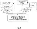
FIG. 2 shows one exemplary method for judging that the battery (01) has stopped to discharge/charge. This is a case when it is judged that the vehicle is parking or stopping from the information of the in-vehicle information controller (03) or when information on connect and disconnect of the battery (01) and the state detector (02) is inputted for example. Or, this is a case when a current value measured by the current measuring means (22) provided in the state detector (02) becomes a judgment threshold value or less recorded in the stationary memory area (24). The judgment may be made only by the in-vehicle information inputting means (27) or only the judgment of the current threshold value or by freely combining them (the part up to now is referred to as a threshold value judgment means). - When the state detector (02) is connected with the battery (01) is referred to as the initial state, i.e., n = 0 (times), and a number of times of judgment when the state is judged that the discharge/charge is stopped by the threshold value judgment means in
FIG. 2 is referred to as n times. A counter value of the timer is set to be t_count = 0. - According to the battery state detecting method of the present embodiment, the SOC, SOH and OCV20hr of the battery corresponding to the initial battery state are stored in the stationary memory area (24) in advance by setting the SOC calculation equation of (2) as SOC0 = SOCref(0), SOHi0 = SOHiref(0) and OCV20hr 0 = OCV20hr ref(0).
- In
FIG. 3 , the counter value of the timer is confirmed with predetermined confirmation timing. When the timer count (t_count) exceeds its measured timing value at the predetermined measuring timing, the current measuring means (22) measures a voltage value Vmes of the battery (01). A relationship between time and the voltage at this time is expressed as follows:
- Then, V_mes(t) - OCV20hr_temp is stored as ΔV(t)_temp (see the equation (4), the acquisition of V_mes(t)).
-
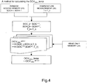
FIG. 4 shows a flow of a method for calculating OCV20hr_temp. As the SOC and SOH in starting to calculate the n-th state, the previous calculated values SOCn-1 and SOH n-1 are used. Measured value T = T_n obtained from the temperature measuring means (20) is used as the temperature of the battery at the present time. When an OCV value after 20 hours presumed from this condition is expressed as OCV20hr_temp, the apparatus (02) has the following relational expression in which OCV20hr ref(h) is correlated with h kinds of conditions combining a plurality of SOC values, SOH values and T values in advance as the reference data:
- OCV20hr ref(h) at the present is determined by using this equation. This is used to determine OCV20hr ref(h) at present. This is one configuration of stable OCV estimating equations. This is used as the n-th time one (selection of OCV20hr _temp):

-
FIG. 5 shows a flow of adding data of ΔV(t)_temp = V_mes(t)-OCV20hr _temp to the temporary memory area (23) per measurement by using V_mes(t) calculated by using the voltage measured value inFIG. 3 and OCV20hr _temp obtained by using the quantity of states SOC, SOH and T inFIG. 4 . - Then, fitting calculation is carried out so as to express ΔV(t)_temp calculated in
FIG. 5 as a sum of two or more (m) relaxation functions per reaction speed fin(t) (i = 1 through m) prepared as predetermined functional type. - In other words, the relaxation function per reaction speed fin(t) is optimized with respect to the data expressed by ΔV(t)_temp.
- Although various calculation methods utilizing regression calculation such as a least-squares method are conceivable as for the fitting method, an error becomes large when the regression calculation is carried out by simply using a sum of exponential functions in this method for calculating ΔV(t)_temp because it turns out as ΔV(20 hr)_temp = 0.
- Then, it is desirable to deduct an inclination of a tangent around ΔV(20 hr)_temp = 0, to introduce a function by which ΔV(20 hr)_temp > 0 always holds and to carry out fitting to the difference by the sum of the exponential functions.
- For simplification, the equation (5) is assumed to be composed of the following four terms hereinafter:

- It becomes easy to prepare the optimized function with respect to ΔV(t)_temp by expressing the equation (10) as follows for example as one embodiment:
-
Function 1 of fast relaxation speed:
-
Function 2 of fast relaxation speed:
-
Function 1 of slow relaxation speed:
-
Function 2 of slow relaxation speed: - However, it is possible to use complicated functions or simplified functions depending on conditions such as computing speed of the sensors, an amount of memory and accuracy required to the sensors.
-
FIGs. 6 and7 illustrate a method for obtaining Fn (t) from ΔV(t)_temp corresponding to an elapsed time from the timer count. Each coefficient is defined so that the functions shown in the equations (10-1 through 10-4) are dominant respectively to the four reference times (10s, 1000s, 36000s, 72000s) as a fitting function in that interval. - At this time, the exemplified reference times (10s, 1000s, 36000s, 72000s) can be determined corresponding to a time constant based on the relaxation speed of the reaction speed within the battery.
- The reference time can be also changed not only by the relaxation speed within the battery but also by the accuracy required to the sensors and timing corresponding to traveling and resting conditions of an actual car.
- As for the determination method of the reference time, it is possible to use a timer within the sensor, to use time of in-vehicle information, typified by car navigation, obtained from the in-vehicle information inputting means or to use their combination.
-
FIG. 6 illustrates a method for obtaining Fn (t) from ΔV(t)_temp when the elapsed time of the timer count is shorter than 20 hours. - When the time t is judged to be shorter than a first reference time (10 seconds here), Fn(t) is calculated by the following equation based on the data after finishing the previous discharge/charge Fn-1(t):

- In the same manner, when the time t is judged to be longer than the first reference time and shorter than a second reference time (1,000 seconds here), Fn (t) is calculated by the following equation based on the data after finishing the previous discharge/charge Fn-1 (t) and the latest data:

- Still more, when the time t is judged to be longer than the second reference time and shorter than a third reference time (36,000 seconds here), Fn(t) is calculated by the following equation based on the data after finishing the previous discharge/charge Fn-1 (t) and the latest data:

- Furthermore, when the time t is judged to be longer than the third reference time and shorter than a fourth reference time (72,000 seconds here), Fn(t) is calculated by the following equation based on the data after finishing the previous discharge/charge Fn-1 (t) and the latest data:

- Then, t = 20 hours is substituted to Fn(t) obtained by the equations (11) through (14) to set as follows:

- Thus, fin (t) and OCV20hr n can be obtained by the equations (11) through (15).
- In
FIG. 7 , when the time t is judged to be more than the fourth reference time, e.g., 20 hours, Fn(t) is calculated by replacing to the following equation (14-2) based on OCV20hr n obtained the latest V_mes(20 hr) and the data of ΔV(t)_temp:
- Then, Fn(t) is calculated by the following equation by not obtaining ΔV(t)_n from Fn(20 hr) but by replacing with the equation (14-2):

- In
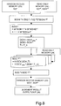
FIG. 8 , SOHin is calculated by using fi(t) calculated in the flows inFIGs. 6 and7 and stored in the temporary memory area (23) and reference data firef (t) and SOHiref recorded in the stationary memory area (24) in advance. - Next, the calculation is made as SOCn = SOCref-n by inputting the respective values to the relational expression of H(OCV20hr n, SOHn, T_n) = SOCref-n in the stationary memory area (24) by using OCV = OCV20hr n obtained in
FIGs. 6 and7 , SOH = SOHn obtained inFIG. 8 and T = t_n obtained inFIG. 4 . - It becomes possible to detect the states of charge and depletion of the battery by comparing SOCn and SOHn calculated as described above with predetermined threshold values.
- The comparison judging means compares SOCn and SOHn with the predetermined threshold values set in advance and judges that the battery is in the depletion state when SOCn is less than the threshold value or when SOHn is more than the threshold value. It is noted that the relationship between the magnitudes of SOH and the depletion level of the battery is reversed depending on system design. In such a case, it is needless to say that it is judged that the battery is in the depletion state when SOHn is less than the predetermined threshold value.
-
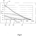
FIG. 9 shows one example of changes of each terms when the relaxation function F(t) is expressed as the equation (10) as one embodiment of optimization of the relaxation function F(t) in the battery state detecting method of the embodiment. -
FIG. 9 is a graph indicating changes of V(t) (= F(t)) when an axis of abscissa represents the elapsed time from the end of discharge/charge. The reference numerals 51 through 54 indicate the changes of each term (Ffast1(t), Ffast2(t), Fslow1(t), Fslow2(t)) in the equation (10), respectively. Still more, thereference numeral 50 indicates a true value and thereference numeral 55 indicates a value of F(t) calculated from the equation (10). This indicates that it becomes possible to estimate ΔV(t) in high precision by using F(t) of the embodiment. - SOH1n after the n-th discharge/charge will be calculated by the following equation by defining a degree of stratification of the slow reaction speed (diffusion of the electrolytic solution and others) as SOH1 in the equation (7):

- In the above equation, fin(t), firef(t) in the equation (7) is calculated further from the sums of two terms (fslow1 n(t) + fslow2 n(t)) and (fslow1 ref(t) + fslow2 ref(t)).
- As one example, 20 times, 50 times and 100 times of discharge and charge cycles have been carried out from an unused state by using a liquid-type lead battery (model size:55D23) manufactured by Furukawa Battery Co., Ltd. and under conditions of 25°C of environment temperature and of 10 % of DOD (Depth of Discharge). Then, SOH1n can be calculated by the following equations from the OCV variation fin(5 hr) when 5 hours has passed (t = 5 hr) from the stop of discharge/charge based on the measured data after discharge/charge of 20 cycles, after discharge/charge of 50 cycles and after discharge/charge of 100 cycles by using the case of 20 cycles as a measure.


-
FIG. 10 shows fslow n(t) /fslow20(t) calculated from the measured data. The reference numerals 61, 62 and 63 represent fslow20(t), fslow50(t) and fslow100(t), respectively and thereference numerals 
- In the same manner, a value 1.63 is obtained as follows:

- Thus, it becomes possible to understand the changes of the state of the battery corresponding to the number of discharge/charge cycles from the variation F(t) of OCV.
- Still more, the OCV when 20 hours has passed after the end of the discharge/charge turns out as follows as one example with respect to 20, 50 and 100 discharge/charge cycles:



-
FIG. 11 shows a relationship between fslown(t)/fslow20(t) and OCV20hr 20. The result shown inFIG. 11 can be used in a stable OCV estimating equation for estimating OCV20hr of the same type of battery. - As described above, the invention can provide the battery state detecting method for detecting the state by evaluating the depletion caused by the reaction processes whose speeds are different. It becomes possible to accurately detect the residual capacity SOC by detecting the depletion level SOH of the battery. Thereby, it becomes possible to assure stable operation of the electric devices and to promote prediction of risk, thus having an effect of keeping safe operation of the vehicle. The invention also provides an effect of reducing an environmental burden by improving precision of the idling stop function.
-
-
FIG. 1 is a diagram showing an overall structure of a state detecting system using a battery state detecting method of an embodiment of the invention. -
FIG. 2 is a flowchart explaining a process for determining a threshold value in the state detecting method of the embodiment. -
FIG. 3 is a flowchart explaining a method for acquiring a voltage measured value in the state detecting method of the embodiment. -
FIG. 4 is a flowchart explaining a method for selecting OCV20hr in the state detecting method of the embodiment. -
FIG. 5 is a flowchart explaining a method for calculating ΔV in the state detecting method of the embodiment. -
FIG. 6 is a flowchart explaining a method for calculating a relaxation function F in the state detecting method of the embodiment. -
FIG. 7 is a flowchart explaining the relaxation function F in the state detecting method of the embodiment. -
FIG. 8 is a flowchart explaining a method for calculating SOH and SOC in the state detecting method of the embodiment. -
FIG. 9 is a graph showing examples of the relaxation function and relaxation function per reaction speed. -
FIG. 10 is a graph showing examples of the relaxation functions per reaction speed and of their ratio. -
FIG. 11 is a graph showing one example of a stable OCV estimating equation. -
FIG. 12 is a graph showing a relationship of stable open channel voltage and SOC. -
FIG. 13 is a graph showing changes of the OCV when the SOC is constant. -
FIG. 14 is a graph showing changes of the OCV when the SOH varies. -
- 01:
- battery
- 02:
- state detecting apparatus
- 03:
- in-vehicle information controller
- 20:
- temperature measuring means
- 21:
- voltage measuring means
- 22:
- current measuring means
- 23:
- memory area (RAM)
- 24:
- stationary memory area (ROM)
- 25:
- processor
- 26:
- judgment result outputting means
- 27:
- in-vehicle state inputting means
- 28:
- timer
- 50:
- true value of ΔV
- 51, 52, 53, 54:
- relaxation function per reaction speed
- 55:
- relaxation function
- 61, 62, 63:
- relaxation function per reaction speed
- 64, 65:
- ratio of relaxation function per reaction speed
- 70:
- stable OCV estimating equation
- 81:
- SOC
- 82, 83, 84, 85:
- OCV

Claims (10)
- A battery state detecting method for estimating at least a quantity of a state of a battery selected from the group consisting of a residual capacity (SOC) and a level of depletion (SOH) of the battery, wherein the method comprises the steps of
preparing a reference relaxation function F(t) that approximates a variation ΔV (t) of an open circuit voltage (OCV) of the battery after an elapsed time t since the battery has stopped to discharge/charge as a function of a predetermined quantity of a state of the battery;
measuring the variation ΔV (t) of the open circuit voltage of the battery from an open circuit voltage (OCVs) during a stable time after fully elapsing a time since the battery has stopped to discharge/charge;
forming a relaxation function Fn (t) that approximates the variation ΔV (t) of the open circuit voltage based on a sum of at least two reaction speed specific relaxation functions fi(t); and
estimating the quantity of state of the battery after the completion of the charge or the discharge based on the relaxation function Fn (t) and the reference relaxation function F (t). - The battery state detecting method according to claim 1, wherein the relaxation function Fn (t) is further prepared as a function of temperature of the battery.
- The battery state detecting method according to claim 1 or 2, wherein a stable OCV estimating equation for estimating the OCV during the stable time is prepared; and
the OCV during the stable time is estimated from the stable OCV estimating equation and a difference between the measured open circuit voltage of the battery and the estimated OCV during the stable time is defined as the variation ΔV (t) of the open circuit voltage. - The battery state detecting method according to claim 3, wherein the OCV during the stable time is an open circuit voltage when 20 hours has elapsed since the battery has stopped to discharge/charge.
- The battery state detecting method according to any one of the claims 1 to 4, wherein the relaxation functions per reaction speed fi(t) are optimized by dividing the measured variation ΔV (t) of the open circuit voltage into components corresponding to at least the first reaction speed and the second reaction speed.
- The battery state detecting method according to Claim 5, wherein the quantity of state is calculated by estimating a quantity of state per reaction speed from the reaction speed specific relaxation functions fi(t) and by totaling them.
- The battery state detecting method according to Claim 6, wherein the relaxation function per reaction speed fin (t) after the end of the n-th discharge/charge is expressed as:

- The battery state detecting method according to any one of claims 1 to 7, comprising:measuring voltage and current of the battery;calculating the variation ΔV (t) of the open circuit voltage corresponding to an elapsed time since the battery has stopped to discharge/charge from the measured voltage when it is judged that the battery has stopped to discharge/charge from the current or a predetermined discharge/charge stopping signal;optimizing a reaction speed specific relaxation function fi(t) whose time constant is shorter than the elapsed time by the variation of the open circuit voltage; andestimating the quantity of state by using an immediately preceding one of the reaction speed specific relaxation functions fi(t) corresponding to the reaction speed which is longer than the time constant together with the optimized relaxation function per reaction speed fi(t).
- The battery state detecting method according to claim 8, wherein the battery is judged to be stopping to discharge/charge when a current value that permits to judge a transient change within the battery is caused by the discharge/charge to be substantially the same with a transient change in a case of open circuit.
- The battery state detecting method according to any one of claims 1 to 9, wherein the battery is judged to be abnormal when the SOC is less than a first threshold value set in advance or when the SOH is more than a second threshold value.
Applications Claiming Priority (1)
| Application Number | Priority Date | Filing Date | Title |
|---|---|---|---|
| JP2008103925A JP4702859B2 (en) | 2008-04-11 | 2008-04-11 | Battery status detection method |
Related Parent Applications (1)
| Application Number | Title | Priority Date | Filing Date |
|---|---|---|---|
| JP2008103925 Previously-Filed-Application | 2008-04-11 |
Publications (3)
| Publication Number | Publication Date |
|---|---|
| EP2108972A2 EP2108972A2 (en) | 2009-10-14 |
| EP2108972A3 EP2108972A3 (en) | 2012-01-25 |
| EP2108972B1 true EP2108972B1 (en) | 2017-12-13 |
Family
ID=40793239
Family Applications (1)
| Application Number | Title | Priority Date | Filing Date |
|---|---|---|---|
| EP09157720.5A Active EP2108972B1 (en) | 2008-04-11 | 2009-04-09 | Method for detecting a battery condition |
Country Status (3)
| Country | Link |
|---|---|
| US (1) | US9170304B2 (en) |
| EP (1) | EP2108972B1 (en) |
| JP (1) | JP4702859B2 (en) |
Families Citing this family (38)
| Publication number | Priority date | Publication date | Assignee | Title |
|---|---|---|---|---|
| JP4897976B2 (en) * | 2009-06-05 | 2012-03-14 | 古河電気工業株式会社 | Method and apparatus for detecting state of power storage device |
| JP5520580B2 (en) * | 2009-11-25 | 2014-06-11 | 古河電気工業株式会社 | Storage battery cell short-circuit detection method and detection device |
| DE102010006965A1 (en) * | 2010-02-05 | 2011-08-11 | Continental Automotive GmbH, 30165 | Apparatus and method for determining a range of a battery characteristic |
| JP5503318B2 (en) * | 2010-02-05 | 2014-05-28 | 古河電気工業株式会社 | Secondary battery charge acceptance limit detection method and apparatus |
| US8872518B2 (en) * | 2010-06-25 | 2014-10-28 | Atieva, Inc. | Determining the state of-charge of batteries via selective sampling of extrapolated open circuit voltage |
| JP4845066B1 (en) * | 2010-08-18 | 2011-12-28 | 古河電気工業株式会社 | Method and apparatus for detecting state of power storage device |
| EP2660615B1 (en) * | 2010-12-28 | 2018-11-21 | Sanyo Electric Co., Ltd. | Battery degradation level detection method |
| US9143889B2 (en) | 2011-07-05 | 2015-09-22 | Htc Corporation | Method of establishing application-related communication between mobile electronic devices, mobile electronic device, non-transitory machine readable media thereof, and media sharing method |
| TWI575978B (en) * | 2011-07-05 | 2017-03-21 | 宏達國際電子股份有限公司 | Wireless service providing method |
| JP2013083612A (en) * | 2011-10-12 | 2013-05-09 | Mitsumi Electric Co Ltd | Battery state measurement method and battery state measurement apparatus |
| CN103842837A (en) * | 2011-10-13 | 2014-06-04 | 丰田自动车株式会社 | Secondary battery control device and method |
| JP6066163B2 (en) | 2012-05-17 | 2017-01-25 | 株式会社Gsユアサ | Open circuit voltage estimation device, state estimation device, and open circuit voltage estimation method |
| CN102749588B (en) * | 2012-06-20 | 2015-03-11 | 南京航空航天大学 | Method for fault diagnosis on basis of storage battery state of charge (SOC) and state of health (SOH) |
| US20140350875A1 (en) * | 2013-05-27 | 2014-11-27 | Scott Allen Mullin | Relaxation model in real-time estimation of state-of-charge in lithium polymer batteries |
| EP3032689B1 (en) * | 2013-08-09 | 2024-04-17 | Hitachi Astemo, Ltd. | Battery control system and vehicle control system |
| JP6407525B2 (en) * | 2013-12-17 | 2018-10-17 | 矢崎総業株式会社 | Battery charging rate estimation device and battery charging rate estimation method |
| JP6443656B2 (en) * | 2014-07-02 | 2018-12-26 | パナソニックIpマネジメント株式会社 | Battery status judgment device |
| US9997944B2 (en) * | 2014-07-07 | 2018-06-12 | Samsung Electronics Co., Ltd. | Method and system of charging a battery |
| CN106597289B (en) * | 2015-10-20 | 2020-09-01 | 郑州宇通客车股份有限公司 | Battery health state measuring and calculating method |
| JP6308223B2 (en) * | 2016-01-06 | 2018-04-11 | トヨタ自動車株式会社 | Battery system for electric vehicles |
| DK3430822T3 (en) * | 2016-03-18 | 2020-03-30 | Sonova Ag | PROCEDURE FOR MONITORING THE CONDITION OF THE BATTERY TO A HEARING, HEARING AND COMPOSITION CONTAINING THE HEARING |
| US10901046B2 (en) * | 2016-07-12 | 2021-01-26 | Envision Aesc Energy Devices, Ltd. | Information processing apparatus, control method, and program |
| KR102655790B1 (en) * | 2016-11-23 | 2024-04-09 | 삼성전자주식회사 | Method and apparatus for estimating battery state |
| CN106933618B (en) * | 2017-01-25 | 2020-03-27 | 上海蔚来汽车有限公司 | System upgrade evaluation method based on system parameter correlation coefficient |
| CN106680730B (en) * | 2017-03-01 | 2023-06-30 | 侬泰轲(上海)检测科技有限责任公司 | Charging and discharging device capable of detecting state of charge and state of charge detection method |
| US20180292463A1 (en) * | 2017-04-10 | 2018-10-11 | Lear Corporation | Method and system for battery state of charge calculation |
| JP6822300B2 (en) * | 2017-04-27 | 2021-01-27 | トヨタ自動車株式会社 | Charge rate estimation method and in-vehicle battery system |
| KR102525676B1 (en) | 2018-02-20 | 2023-04-24 | 에스케이온 주식회사 | Battery management system |
| FR3094796B1 (en) * | 2019-04-03 | 2021-08-06 | Renault Sas | Method of initializing the state of charge of a battery |
| CN110154830A (en) * | 2019-04-11 | 2019-08-23 | 汉腾汽车有限公司 | A kind of power battery instrument SOC display control strategy |
| JP7396813B2 (en) * | 2019-06-06 | 2023-12-12 | パナソニック インテレクチュアル プロパティ コーポレーション オブ アメリカ | Open circuit voltage measurement method, open circuit voltage measurement device, and program |
| JP2020201081A (en) * | 2019-06-07 | 2020-12-17 | 本田技研工業株式会社 | Method for determining minute short-circuiting of lithium ion secondary battery |
| KR102781341B1 (en) | 2019-11-05 | 2025-03-12 | 주식회사 엘지에너지솔루션 | Apparatus for battery diagnosis, nergy storage system including same, and method thereof |
| KR102784717B1 (en) * | 2019-12-11 | 2025-03-19 | 주식회사 엘지에너지솔루션 | Battery management system, battery management method, battery pack, and electric vehicle |
| CN113533964B (en) * | 2020-03-30 | 2024-02-13 | 郑州深澜动力科技有限公司 | Calculation method and device for displaying state of charge |
| CN111765157B (en) * | 2020-06-29 | 2022-01-25 | Oppo(重庆)智能科技有限公司 | Manufacturing execution system, electronic device assembly method, and computer readable medium |
| JP7669196B2 (en) | 2021-06-02 | 2025-04-28 | 株式会社日立製作所 | State determination device, secondary battery system, and state determination method |
| CN114594318B (en) * | 2021-06-08 | 2024-08-27 | 浙江科律检测技术有限公司 | Metering error monitoring method for alternating-current charging pile and storage medium |
Family Cites Families (11)
| Publication number | Priority date | Publication date | Assignee | Title |
|---|---|---|---|---|
| US6456988B1 (en) | 1997-03-12 | 2002-09-24 | U.S. Nanocorp Inc. | Method for determining state-of-health using an intelligent system |
| US6366054B1 (en) * | 2001-05-02 | 2002-04-02 | Honeywell International Inc. | Method for determining state of charge of a battery by measuring its open circuit voltage |
| DE10161640A1 (en) | 2001-12-14 | 2003-07-10 | Vb Autobatterie Gmbh | Method for determining the operating state of a storage battery |
| JP2003307556A (en) * | 2002-02-15 | 2003-10-31 | Yazaki Corp | Battery open circuit voltage estimation method and apparatus |
| US6850038B2 (en) * | 2002-05-14 | 2005-02-01 | Yazaki Corporation | Method of estimating state of charge and open circuit voltage of battery, and method and device for computing degradation degree of battery |
| US6892148B2 (en) | 2002-12-29 | 2005-05-10 | Texas Instruments Incorporated | Circuit and method for measurement of battery capacity fade |
| JP4015128B2 (en) | 2003-07-09 | 2007-11-28 | 古河電気工業株式会社 | CHARGE RATE ESTIMATION METHOD, CHARGE RATE ESTIMATION DEVICE, BATTERY SYSTEM, AND VEHICLE BATTERY SYSTEM |
| JP4255795B2 (en) | 2003-09-30 | 2009-04-15 | 本田技研工業株式会社 | Open circuit voltage detection device and remaining capacity detection device of power storage device |
| KR100759706B1 (en) * | 2005-05-11 | 2007-09-17 | 주식회사 엘지화학 | Method of estimating soc of battery for hybrid electric vehicle |
| WO2006129802A1 (en) | 2005-06-03 | 2006-12-07 | The Furukawa Electric Co., Ltd. | Charge ratio/remaining capacity estimation method, battery state sensor, and battery power source system |
| US7928735B2 (en) * | 2007-07-23 | 2011-04-19 | Yung-Sheng Huang | Battery performance monitor |
-
2008
- 2008-04-11 JP JP2008103925A patent/JP4702859B2/en active Active
-
2009
- 2009-04-09 US US12/420,945 patent/US9170304B2/en active Active
- 2009-04-09 EP EP09157720.5A patent/EP2108972B1/en active Active
Non-Patent Citations (1)
| Title |
|---|
| None * |
Also Published As
| Publication number | Publication date |
|---|---|
| EP2108972A2 (en) | 2009-10-14 |
| EP2108972A3 (en) | 2012-01-25 |
| US20090256524A1 (en) | 2009-10-15 |
| US9170304B2 (en) | 2015-10-27 |
| JP4702859B2 (en) | 2011-06-15 |
| JP2009257784A (en) | 2009-11-05 |
Similar Documents
| Publication | Publication Date | Title |
|---|---|---|
| US9170304B2 (en) | Method for estimating a quantity of a state of a battery | |
| US20250035709A1 (en) | Remaining capability evaluation method for secondary battery, remaining capability evaluation program for secondary battery, computation device, and remaining capability evaluation system | |
| US10802080B2 (en) | Battery system in vehicle and aging deterioration estimation method for battery | |
| US11575271B2 (en) | SOC and SOH estimation methods of battery pack | |
| EP1917536B1 (en) | System and method for estimating a state vector associated with a battery | |
| EP3306735B1 (en) | Device for estimating degree of battery degradation, and estimation method | |
| US10436848B2 (en) | Battery capacity active estimation method used for electric vehicle | |
| US8004243B2 (en) | Battery capacity estimating method and apparatus | |
| CN105467325B (en) | The method and system that battery capacity degeneration solves | |
| EP3842816B1 (en) | Soh estimation method of battery pack | |
| US10090686B2 (en) | Electrical storage system | |
| EP3839536B1 (en) | Battery state estimating apparatus | |
| US20180236890A1 (en) | System and Method of Battery Monitoring | |
| CN102428379B (en) | State detection method for electric storage device, and apparatus therefor | |
| US8872518B2 (en) | Determining the state of-charge of batteries via selective sampling of extrapolated open circuit voltage | |
| US9588187B2 (en) | Method and apparatus for estimating battery life during driving of electrical vehicle (EV) | |
| US20200018797A1 (en) | A battery cell state of charge estimation method and a battery state monitoring system | |
| Piłatowicz et al. | Determination of the lead-acid battery's dynamic response using Butler-Volmer equation for advanced battery management systems in automotive applications | |
| JP5041442B2 (en) | Method for detecting state of power storage device | |
| US20140184233A1 (en) | Method for checking deterioration of battery | |
| CN112912745A (en) | Method for determining the state of charge and the state of ageing of an electrochemical cell from an open circuit voltage diagram | |
| US11852690B2 (en) | Method and system for estimating degradation of battery for vehicle | |
| JP5413592B2 (en) | Secondary battery charge state estimation control device | |
| KR101261149B1 (en) | Method for estimating state of charge of battery | |
| US12455321B2 (en) | Method for determining a capacity of an HV battery |
Legal Events
| Date | Code | Title | Description |
|---|---|---|---|
| PUAI | Public reference made under article 153(3) epc to a published international application that has entered the european phase |
Free format text: ORIGINAL CODE: 0009012 |
|
| AK | Designated contracting states |
Kind code of ref document: A2 Designated state(s): AT BE BG CH CY CZ DE DK EE ES FI FR GB GR HR HU IE IS IT LI LT LU LV MC MK MT NL NO PL PT RO SE SI SK TR |
|
| RAP1 | Party data changed (applicant data changed or rights of an application transferred) |
Owner name: FURUKAWA ELECTRIC CO., LTD. |
|
| RAP1 | Party data changed (applicant data changed or rights of an application transferred) |
Owner name: FURUKAWA ELECTRIC CO., LTD. |
|
| PUAL | Search report despatched |
Free format text: ORIGINAL CODE: 0009013 |
|
| AK | Designated contracting states |
Kind code of ref document: A3 Designated state(s): AT BE BG CH CY CZ DE DK EE ES FI FR GB GR HR HU IE IS IT LI LT LU LV MC MK MT NL NO PL PT RO SE SI SK TR |
|
| AX | Request for extension of the european patent |
Extension state: AL BA RS |
|
| RIC1 | Information provided on ipc code assigned before grant |
Ipc: G01R 31/36 20060101AFI20111220BHEP |
|
| 17P | Request for examination filed |
Effective date: 20120710 |
|
| 17Q | First examination report despatched |
Effective date: 20140306 |
|
| GRAP | Despatch of communication of intention to grant a patent |
Free format text: ORIGINAL CODE: EPIDOSNIGR1 |
|
| STAA | Information on the status of an ep patent application or granted ep patent |
Free format text: STATUS: GRANT OF PATENT IS INTENDED |
|
| INTG | Intention to grant announced |
Effective date: 20170705 |
|
| GRAS | Grant fee paid |
Free format text: ORIGINAL CODE: EPIDOSNIGR3 |
|
| GRAA | (expected) grant |
Free format text: ORIGINAL CODE: 0009210 |
|
| STAA | Information on the status of an ep patent application or granted ep patent |
Free format text: STATUS: THE PATENT HAS BEEN GRANTED |
|
| AK | Designated contracting states |
Kind code of ref document: B1 Designated state(s): AT BE BG CH CY CZ DE DK EE ES FI FR GB GR HR HU IE IS IT LI LT LU LV MC MK MT NL NO PL PT RO SE SI SK TR |
|
| REG | Reference to a national code |
Ref country code: GB Ref legal event code: FG4D |
|
| REG | Reference to a national code |
Ref country code: AT Ref legal event code: REF Ref document number: 954908 Country of ref document: AT Kind code of ref document: T Effective date: 20171215 Ref country code: CH Ref legal event code: EP |
|
| REG | Reference to a national code |
Ref country code: IE Ref legal event code: FG4D |
|
| REG | Reference to a national code |
Ref country code: DE Ref legal event code: R096 Ref document number: 602009049836 Country of ref document: DE |
|
| REG | Reference to a national code |
Ref country code: NL Ref legal event code: MP Effective date: 20171213 |
|
| REG | Reference to a national code |
Ref country code: LT Ref legal event code: MG4D |
|
| PG25 | Lapsed in a contracting state [announced via postgrant information from national office to epo] |
Ref country code: LT Free format text: LAPSE BECAUSE OF FAILURE TO SUBMIT A TRANSLATION OF THE DESCRIPTION OR TO PAY THE FEE WITHIN THE PRESCRIBED TIME-LIMIT Effective date: 20171213 Ref country code: NO Free format text: LAPSE BECAUSE OF FAILURE TO SUBMIT A TRANSLATION OF THE DESCRIPTION OR TO PAY THE FEE WITHIN THE PRESCRIBED TIME-LIMIT Effective date: 20180313 Ref country code: SE Free format text: LAPSE BECAUSE OF FAILURE TO SUBMIT A TRANSLATION OF THE DESCRIPTION OR TO PAY THE FEE WITHIN THE PRESCRIBED TIME-LIMIT Effective date: 20171213 Ref country code: FI Free format text: LAPSE BECAUSE OF FAILURE TO SUBMIT A TRANSLATION OF THE DESCRIPTION OR TO PAY THE FEE WITHIN THE PRESCRIBED TIME-LIMIT Effective date: 20171213 |
|
| REG | Reference to a national code |
Ref country code: AT Ref legal event code: MK05 Ref document number: 954908 Country of ref document: AT Kind code of ref document: T Effective date: 20171213 |
|
| PG25 | Lapsed in a contracting state [announced via postgrant information from national office to epo] |
Ref country code: BG Free format text: LAPSE BECAUSE OF FAILURE TO SUBMIT A TRANSLATION OF THE DESCRIPTION OR TO PAY THE FEE WITHIN THE PRESCRIBED TIME-LIMIT Effective date: 20180313 Ref country code: HR Free format text: LAPSE BECAUSE OF FAILURE TO SUBMIT A TRANSLATION OF THE DESCRIPTION OR TO PAY THE FEE WITHIN THE PRESCRIBED TIME-LIMIT Effective date: 20171213 Ref country code: GR Free format text: LAPSE BECAUSE OF FAILURE TO SUBMIT A TRANSLATION OF THE DESCRIPTION OR TO PAY THE FEE WITHIN THE PRESCRIBED TIME-LIMIT Effective date: 20180314 Ref country code: LV Free format text: LAPSE BECAUSE OF FAILURE TO SUBMIT A TRANSLATION OF THE DESCRIPTION OR TO PAY THE FEE WITHIN THE PRESCRIBED TIME-LIMIT Effective date: 20171213 |
|
| PG25 | Lapsed in a contracting state [announced via postgrant information from national office to epo] |
Ref country code: NL Free format text: LAPSE BECAUSE OF FAILURE TO SUBMIT A TRANSLATION OF THE DESCRIPTION OR TO PAY THE FEE WITHIN THE PRESCRIBED TIME-LIMIT Effective date: 20171213 |
|
| PG25 | Lapsed in a contracting state [announced via postgrant information from national office to epo] |
Ref country code: ES Free format text: LAPSE BECAUSE OF FAILURE TO SUBMIT A TRANSLATION OF THE DESCRIPTION OR TO PAY THE FEE WITHIN THE PRESCRIBED TIME-LIMIT Effective date: 20171213 Ref country code: CZ Free format text: LAPSE BECAUSE OF FAILURE TO SUBMIT A TRANSLATION OF THE DESCRIPTION OR TO PAY THE FEE WITHIN THE PRESCRIBED TIME-LIMIT Effective date: 20171213 Ref country code: CY Free format text: LAPSE BECAUSE OF FAILURE TO SUBMIT A TRANSLATION OF THE DESCRIPTION OR TO PAY THE FEE WITHIN THE PRESCRIBED TIME-LIMIT Effective date: 20171213 Ref country code: SK Free format text: LAPSE BECAUSE OF FAILURE TO SUBMIT A TRANSLATION OF THE DESCRIPTION OR TO PAY THE FEE WITHIN THE PRESCRIBED TIME-LIMIT Effective date: 20171213 Ref country code: EE Free format text: LAPSE BECAUSE OF FAILURE TO SUBMIT A TRANSLATION OF THE DESCRIPTION OR TO PAY THE FEE WITHIN THE PRESCRIBED TIME-LIMIT Effective date: 20171213 |
|
| PG25 | Lapsed in a contracting state [announced via postgrant information from national office to epo] |
Ref country code: RO Free format text: LAPSE BECAUSE OF FAILURE TO SUBMIT A TRANSLATION OF THE DESCRIPTION OR TO PAY THE FEE WITHIN THE PRESCRIBED TIME-LIMIT Effective date: 20171213 Ref country code: PL Free format text: LAPSE BECAUSE OF FAILURE TO SUBMIT A TRANSLATION OF THE DESCRIPTION OR TO PAY THE FEE WITHIN THE PRESCRIBED TIME-LIMIT Effective date: 20171213 Ref country code: IS Free format text: LAPSE BECAUSE OF FAILURE TO SUBMIT A TRANSLATION OF THE DESCRIPTION OR TO PAY THE FEE WITHIN THE PRESCRIBED TIME-LIMIT Effective date: 20180413 Ref country code: AT Free format text: LAPSE BECAUSE OF FAILURE TO SUBMIT A TRANSLATION OF THE DESCRIPTION OR TO PAY THE FEE WITHIN THE PRESCRIBED TIME-LIMIT Effective date: 20171213 Ref country code: IT Free format text: LAPSE BECAUSE OF FAILURE TO SUBMIT A TRANSLATION OF THE DESCRIPTION OR TO PAY THE FEE WITHIN THE PRESCRIBED TIME-LIMIT Effective date: 20171213 |
|
| REG | Reference to a national code |
Ref country code: DE Ref legal event code: R097 Ref document number: 602009049836 Country of ref document: DE |
|
| PLBE | No opposition filed within time limit |
Free format text: ORIGINAL CODE: 0009261 |
|
| STAA | Information on the status of an ep patent application or granted ep patent |
Free format text: STATUS: NO OPPOSITION FILED WITHIN TIME LIMIT |
|
| 26N | No opposition filed |
Effective date: 20180914 |
|
| PG25 | Lapsed in a contracting state [announced via postgrant information from national office to epo] |
Ref country code: DK Free format text: LAPSE BECAUSE OF FAILURE TO SUBMIT A TRANSLATION OF THE DESCRIPTION OR TO PAY THE FEE WITHIN THE PRESCRIBED TIME-LIMIT Effective date: 20171213 Ref country code: MC Free format text: LAPSE BECAUSE OF FAILURE TO SUBMIT A TRANSLATION OF THE DESCRIPTION OR TO PAY THE FEE WITHIN THE PRESCRIBED TIME-LIMIT Effective date: 20171213 |
|
| REG | Reference to a national code |
Ref country code: CH Ref legal event code: PL |
|
| REG | Reference to a national code |
Ref country code: BE Ref legal event code: MM Effective date: 20180430 |
|
| GBPC | Gb: european patent ceased through non-payment of renewal fee |
Effective date: 20180409 |
|
| REG | Reference to a national code |
Ref country code: IE Ref legal event code: MM4A |
|
| PG25 | Lapsed in a contracting state [announced via postgrant information from national office to epo] |
Ref country code: LU Free format text: LAPSE BECAUSE OF NON-PAYMENT OF DUE FEES Effective date: 20180409 |
|
| PG25 | Lapsed in a contracting state [announced via postgrant information from national office to epo] |
Ref country code: BE Free format text: LAPSE BECAUSE OF NON-PAYMENT OF DUE FEES Effective date: 20180430 Ref country code: CH Free format text: LAPSE BECAUSE OF NON-PAYMENT OF DUE FEES Effective date: 20180430 Ref country code: GB Free format text: LAPSE BECAUSE OF NON-PAYMENT OF DUE FEES Effective date: 20180409 Ref country code: LI Free format text: LAPSE BECAUSE OF NON-PAYMENT OF DUE FEES Effective date: 20180430 Ref country code: SI Free format text: LAPSE BECAUSE OF FAILURE TO SUBMIT A TRANSLATION OF THE DESCRIPTION OR TO PAY THE FEE WITHIN THE PRESCRIBED TIME-LIMIT Effective date: 20171213 |
|
| PG25 | Lapsed in a contracting state [announced via postgrant information from national office to epo] |
Ref country code: IE Free format text: LAPSE BECAUSE OF NON-PAYMENT OF DUE FEES Effective date: 20180409 Ref country code: FR Free format text: LAPSE BECAUSE OF NON-PAYMENT OF DUE FEES Effective date: 20180430 |
|
| PG25 | Lapsed in a contracting state [announced via postgrant information from national office to epo] |
Ref country code: MT Free format text: LAPSE BECAUSE OF NON-PAYMENT OF DUE FEES Effective date: 20180409 |
|
| PG25 | Lapsed in a contracting state [announced via postgrant information from national office to epo] |
Ref country code: TR Free format text: LAPSE BECAUSE OF FAILURE TO SUBMIT A TRANSLATION OF THE DESCRIPTION OR TO PAY THE FEE WITHIN THE PRESCRIBED TIME-LIMIT Effective date: 20171213 |
|
| PG25 | Lapsed in a contracting state [announced via postgrant information from national office to epo] |
Ref country code: PT Free format text: LAPSE BECAUSE OF FAILURE TO SUBMIT A TRANSLATION OF THE DESCRIPTION OR TO PAY THE FEE WITHIN THE PRESCRIBED TIME-LIMIT Effective date: 20171213 Ref country code: HU Free format text: LAPSE BECAUSE OF FAILURE TO SUBMIT A TRANSLATION OF THE DESCRIPTION OR TO PAY THE FEE WITHIN THE PRESCRIBED TIME-LIMIT; INVALID AB INITIO Effective date: 20090409 |
|
| PG25 | Lapsed in a contracting state [announced via postgrant information from national office to epo] |
Ref country code: MK Free format text: LAPSE BECAUSE OF NON-PAYMENT OF DUE FEES Effective date: 20171213 |
|
| P01 | Opt-out of the competence of the unified patent court (upc) registered |
Effective date: 20230512 |
|
| PGFP | Annual fee paid to national office [announced via postgrant information from national office to epo] |
Ref country code: DE Payment date: 20250305 Year of fee payment: 17 |