EP1917536B1 - System and method for estimating a state vector associated with a battery - Google Patents
System and method for estimating a state vector associated with a battery Download PDFInfo
- Publication number
- EP1917536B1 EP1917536B1 EP06783700.5A EP06783700A EP1917536B1 EP 1917536 B1 EP1917536 B1 EP 1917536B1 EP 06783700 A EP06783700 A EP 06783700A EP 1917536 B1 EP1917536 B1 EP 1917536B1
- Authority
- EP
- European Patent Office
- Prior art keywords
- battery
- state vector
- computer
- kalman filter
- calculating
- Prior art date
- Legal status (The legal status is an assumption and is not a legal conclusion. Google has not performed a legal analysis and makes no representation as to the accuracy of the status listed.)
- Active
Links
Images


Classifications
-
- G—PHYSICS
- G01—MEASURING; TESTING
- G01R—MEASURING ELECTRIC VARIABLES; MEASURING MAGNETIC VARIABLES
- G01R31/00—Arrangements for testing electric properties; Arrangements for locating electric faults; Arrangements for electrical testing characterised by what is being tested not provided for elsewhere
- G01R31/36—Arrangements for testing, measuring or monitoring the electrical condition of accumulators or electric batteries, e.g. capacity or state of charge [SoC]
- G01R31/382—Arrangements for monitoring battery or accumulator variables, e.g. SoC
- G01R31/3835—Arrangements for monitoring battery or accumulator variables, e.g. SoC involving only voltage measurements
-
- G—PHYSICS
- G01—MEASURING; TESTING
- G01R—MEASURING ELECTRIC VARIABLES; MEASURING MAGNETIC VARIABLES
- G01R31/00—Arrangements for testing electric properties; Arrangements for locating electric faults; Arrangements for electrical testing characterised by what is being tested not provided for elsewhere
- G01R31/36—Arrangements for testing, measuring or monitoring the electrical condition of accumulators or electric batteries, e.g. capacity or state of charge [SoC]
- G01R31/367—Software therefor, e.g. for battery testing using modelling or look-up tables
-
- G—PHYSICS
- G01—MEASURING; TESTING
- G01R—MEASURING ELECTRIC VARIABLES; MEASURING MAGNETIC VARIABLES
- G01R31/00—Arrangements for testing electric properties; Arrangements for locating electric faults; Arrangements for electrical testing characterised by what is being tested not provided for elsewhere
- G01R31/36—Arrangements for testing, measuring or monitoring the electrical condition of accumulators or electric batteries, e.g. capacity or state of charge [SoC]
- G01R31/382—Arrangements for monitoring battery or accumulator variables, e.g. SoC
- G01R31/3842—Arrangements for monitoring battery or accumulator variables, e.g. SoC combining voltage and current measurements
Definitions
- the present invention relates to system and method for estimating a state vector associated with a battery.
- Batteries are used in a wide variety of electronic and electrical devices. It is desirable to be able to estimate the internal state of a battery, including state-of-charge (SOC).
- SOC is a value that indicates the present available capacity of the battery that may be used to do work.
- a battery monitoring system may measure a history of electrical current input to a battery and an output voltage from the battery to provide an estimate of a battery state.
- a battery generally discharges over a time interval when it is electrically unloaded and a state of the battery changes during this time interval.
- a battery monitoring system interrupts its history of measurements and calculations during this time interval.
- a disadvantage of this system is that it cannot accurately determine the state of the battery at a time when a battery is electrically coupled to a load circuit after it has been electrically decoupled from the load circuit for the time interval.
- the inventor herein has recognized a need for a system and a method for estimating a state vector associated with a battery at a time when a battery is electrically coupled to a load circuit, after it has been electrically decoupled from the load circuit for the time interval.
- a method for estimating a state vector associated with a battery in accordance with an exemplary embodiment includes determining a time interval that the battery has been electrically decoupled from a load circuit. The time interval starts at a first time. The method further includes obtaining a first state vector associated with the battery from a memory. The first state vector is determined prior to the first time. The method further includes calculating a second predicted state vector associated with the battery based on the first state vector and the time interval. The method further includes measuring a battery voltage output from the battery to obtain a first battery voltage value after the first time interval when the battery is electrically recoupled to the load circuit. The method further includes estimating a second battery voltage value associated with the battery based on the second predicted state vector. The method further includes calculating a voltage error value based on the first battery voltage value and second battery voltage value. The method further includes calculating a third estimated state vector associated with the battery based on the second predicted state vector and a voltage error value.
- a system for estimated a state vector associated with a battery in accordance with another exemplary embodiment includes a voltage sensor configured to measure a voltage output from the battery.
- the system further includes a computer operably coupled to the voltage sensor.
- the computer is configured to determine a time interval that the battery has been electrically decoupled from a load circuit. The time interval starts at a first time.
- the computer is further configured to obtain a first state vector associated with the battery from a memory. The first state vector is determined prior to the first time.
- the computer is further configured to calculate a second predicted state vector associated with the battery based on the first state vector and the time interval.
- the computer is further configured to induce the voltage sensor to measure the voltage output from the battery to obtain a first battery voltage value after the first time interval when the battery is electrically coupled to the load circuit.
- the computer is further configured to estimate a second battery voltage value associated with the battery based on the second predicted state vector.
- the computer is further configured to calculate a voltage error value based on the first battery voltage value and the second battery voltage value.
- the computer is further configured to calculate a third estimated state vector associated with the battery based on the second predicted state vector and the voltage error value.
- the article of manufacture includes a computer storage medium having a computer program encoded therein for estimating a state vector associated with a battery.
- the computer storage medium includes code for determining a time interval that the battery has been electrically decoupled from a load circuit. The time interval starts at a first time.
- the computer storage medium further includes code for obtaining a first state vector associated with the battery from a memory. The first state vector is determined prior to the first time.
- the computer storage medium further includes code for calculating a second predicted state vector associated with the battery based on the first state vector and the time interval.
- the computer storage medium further includes code for measuring a battery voltage output from the battery to obtain a first battery voltage value after the first time interval when the battery is electrically coupled to the load circuit.
- the computer storage medium further includes code for estimating a second battery voltage value associated with the battery based on the second predicted state vector.
- the computer storage medium further includes code for calculating a voltage error value based on the first battery voltage value and the second battery voltage value.
- the computer storage medium further includes code for calculating a third estimated state vector associated with the battery based on the second predicted state vector and the voltage error value.
- the battery 12 includes at least a battery cell 14. Of course, the battery 12 can include a plurality of additional battery cells.
- the system 10 includes one or more voltage sensors 20, a load circuit 26, and a computational unit such as a computer 28, and may also include one or more of a temperature sensor 22, and a current sensor 24.
- the voltage sensor 20 is provided to generate a first output signal indicative of the voltage produced by one or more of the battery cells of the battery 12.
- the voltage sensor 20 is electrically coupled between the I/O interface 46 of the computer 28 and the battery 12.
- the voltage sensor 20 transfers the first output signal to the computer 28.
- a single voltage sensor will be described herein. However, it should be noted that in an alternate embodiment of system 10 a plurality of voltage sensors (e.g., one voltage sensor per battery cell) are utilized in system 10.
- the temperature sensor 22 is provided to generate a second output signal indicative of one or more temperatures of the battery 12.
- the temperature sensor 22 is disposed proximate the battery 12 and is electrically coupled to the I/O interface 46 of the computer 28.
- the temperature sensor 22 transfers the second output signal to the computer 28.
- a single temperature sensor will be described herein. However, it should be noted that in an alternate embodiment of system 10 a plurality of temperature sensors (e.g., one temperature sensor per battery cell) are utilized in system 10.
- the current sensor 24 is provided to generate a third output signal indicative of a current sourced or sunk by the battery cells of the battery 12.
- the current sensor 24 is electrically coupled between the battery 12 and the load circuit 26.
- the current sensor 24 is further electrically coupled to the I/O interface 46 of the computer 28.
- the current sensor 24 transfers the third output signal to the computer 28.
- the load circuit 26 is electrically coupled to the current sensor 24 and sinks or sources a current from the battery 12.
- the load circuit 26 comprises any electrical device that can be electrically coupled to the battery 12.
- the computer 28 is provided for determining a state vector associated with the battery 12, as will be explained in greater detail below.
- the computer 28 includes a central processing unit (CPU) 40, a read-only memory (ROM) 44, a volatile memory such as a random access memory (RAM) 45 and an input/output (I/O) interface 46.
- the CPU 40 operably communicates with the ROM 44, the RAM 45, and the I/O interface 46.
- the CPU 40 includes a clock 42.
- the computer readable media including the ROM 44 and the RAM 45 may be implemented using any of a number of known memory devices such as PROMs, EPROMs, EEPROMS, flash memory or any other electric, magnetic, optical or combination memory device capable of storing data, some of which represent executable instructions used by the CPU 40.
- the state vector includes at least a state of charge (SOC) value associated with the battery 12.
- SOC value is a value from 0 to 100 percent, that indicates a present available capacity of the battery 12 that may be used to do work.
- the estimated state vector is determined when the load circuit 26 is energized utilizing the following parameters: (i) measured battery voltage (ii) a stored prior estimated state vector (including an SOC value); and (iii) a time interval that the load circuit 12 was de-energized or electrically de-coupled from the battery 12.
- the duration of time that the device was de-energized may be measured using the clock 42 of the computer 28.
- Y k ⁇ R x k x k p x k
- the foregoing equation computes a posterior probability density p ( x k
- the circumflex symbol indicates an estimated quantity (e.g., x ⁇ indicates an estimate of the true quantity x ).
- the superscript symbol "-" indicates an a priori estimate ( i.e., a prediction of a quantity's present value based on past data).
- the superscript symbol "+” indicates an a posteriori estimate ( e.g. , x ⁇ k + is the estimate of true quantity x at time index k based on all measurements taken up to and including time k ).
- the symbol ⁇ xy E [xy T ] indicates the correlation or cross correlation of the variables in its subscript (the quantities described herein are zero-mean, so the correlations are identical to covariances).
- the symbol ⁇ x indicates the same quantity as ⁇ xx .
- the superscript "T" is a matrix/vector transpose operator.
- the computer 28 determines a time interval that the battery 12 has been electrically decoupled from the load circuit 26.
- the time interval starts at a first time.
- the computer 28 obtains a first state vector x k -1 associated with the battery 12 from a memory 46.
- the first state vector x k -1 is determined prior to the first time.
- the computer 28 induces a voltage sensor 20 to measure a battery voltage output from the battery 12 to obtain a first battery voltage value after the first time interval when the battery 12 is electrically coupled to the load circuit 26.
- the computer 28 calculates a voltage error value based on the first battery voltage value and the second battery voltage value.
- the third predicted state vector x ⁇ k + is the most accurate estimate of the true state of the battery 12 produced by the foregoing method.
- ⁇ k ⁇ f x k , u k , w k , k ⁇ x k
- v k v ⁇ k
- the computer 28 determines a time interval that a battery 12 has been electrically decoupled from a load circuit 26.
- the time interval starts at a first time.
- the computer 28 obtains a first state vector x ⁇ k ⁇ 1 + associated with the battery 12 from the memory 46.
- the first state vector x ⁇ k ⁇ 1 + is determined prior to the first time.
- the computer 28 induces the voltage sensor 20 to measure a battery voltage output from the battery 12 to obtain a first battery voltage value after the first time interval when the battery 12 is electrically coupled to the load circuit 26.
- the computer 28 calculates a voltage error value based on the first battery voltage value and the second battery voltage value.
- the estimated state vector x ⁇ k of the battery 12 can be calculated utilizing a linear Kalman filter, a nonlinear sigma-point Kalman filter, a square-root linear Kalman filter, a square-root extended Kalman filter, a square-root sigma-point Kalman filter, a particle filter, and the like.
- the system and methods for estimating a state vector associated with a battery provide a substantial advantage over other systems and methods.
- the system and methods provide a technical effect of accurately estimating a state vector associated with the battery at a time when a battery is electrically coupled to a load circuit, after it has been electrically decoupled from the load circuit for the time interval.
- the above-described methods can also be embodied in the form of computer program code, for example, whether stored in a storage medium, loaded into and/or executed by a computer, or transmitted over some transmission medium, loaded into and/or executed by a computer, or transmitted over some transmission medium, such as over electrical wiring or cabling, through fiber optics, or via electromagnetic radiation, wherein, when the computer program code is loaded into an executed by a computer, the computer becomes an apparatus for practicing the methods.
- the computer program code segments configure the microprocessor to create specific logic circuits.
Landscapes
- Physics & Mathematics (AREA)
- General Physics & Mathematics (AREA)
- Secondary Cells (AREA)
- Charge And Discharge Circuits For Batteries Or The Like (AREA)
- Tests Of Electric Status Of Batteries (AREA)
Description
- The present invention relates to system and method for estimating a state vector associated with a battery.
- Batteries are used in a wide variety of electronic and electrical devices. It is desirable to be able to estimate the internal state of a battery, including state-of-charge (SOC). The SOC is a value that indicates the present available capacity of the battery that may be used to do work. A battery monitoring system may measure a history of electrical current input to a battery and an output voltage from the battery to provide an estimate of a battery state.
- A battery generally discharges over a time interval when it is electrically unloaded and a state of the battery changes during this time interval. A battery monitoring system, however, interrupts its history of measurements and calculations during this time interval. A disadvantage of this system is that it cannot accurately determine the state of the battery at a time when a battery is electrically coupled to a load circuit after it has been electrically decoupled from the load circuit for the time interval.
- Thus, the inventor herein has recognized a need for a system and a method for estimating a state vector associated with a battery at a time when a battery is electrically coupled to a load circuit, after it has been electrically decoupled from the load circuit for the time interval.
- Background art is further described in
US 6441586 ; Gregory L. Plett, "Extended Kalman filtering for battery management systems of LiPB-based HEV battery packs" in J. of Power Sources, vol. 134, n. 2, 2004, pp. 277-292; B. S. Bhangu et al., "Nonlinear Observers for Predicting State-of-Charge and State-of-Health of Lead-Acid Batteries for Hybrid-Electric Vehicles" in IEEE Transactions on Vehicular Technology, vol. 54, n. 3, 2005, pp. 783-794,US 6534954 andUS 2005046388 . - A method for estimating a state vector associated with a battery in accordance with an exemplary embodiment is provided. The method includes determining a time interval that the battery has been electrically decoupled from a load circuit. The time interval starts at a first time. The method further includes obtaining a first state vector associated with the battery from a memory. The first state vector is determined prior to the first time. The method further includes calculating a second predicted state vector associated with the battery based on the first state vector and the time interval. The method further includes measuring a battery voltage output from the battery to obtain a first battery voltage value after the first time interval when the battery is electrically recoupled to the load circuit. The method further includes estimating a second battery voltage value associated with the battery based on the second predicted state vector. The method further includes calculating a voltage error value based on the first battery voltage value and second battery voltage value. The method further includes calculating a third estimated state vector associated with the battery based on the second predicted state vector and a voltage error value.
- A system for estimated a state vector associated with a battery in accordance with another exemplary embodiment is provided. The system includes a voltage sensor configured to measure a voltage output from the battery. The system further includes a computer operably coupled to the voltage sensor. The computer is configured to determine a time interval that the battery has been electrically decoupled from a load circuit. The time interval starts at a first time. The computer is further configured to obtain a first state vector associated with the battery from a memory. The first state vector is determined prior to the first time. The computer is further configured to calculate a second predicted state vector associated with the battery based on the first state vector and the time interval. The computer is further configured to induce the voltage sensor to measure the voltage output from the battery to obtain a first battery voltage value after the first time interval when the battery is electrically coupled to the load circuit. The computer is further configured to estimate a second battery voltage value associated with the battery based on the second predicted state vector. The computer is further configured to calculate a voltage error value based on the first battery voltage value and the second battery voltage value. The computer is further configured to calculate a third estimated state vector associated with the battery based on the second predicted state vector and the voltage error value.
- An article of manufacture in accordance with still another exemplary embodiment is provided. The article of manufacture includes a computer storage medium having a computer program encoded therein for estimating a state vector associated with a battery. The computer storage medium includes code for determining a time interval that the battery has been electrically decoupled from a load circuit. The time interval starts at a first time. The computer storage medium further includes code for obtaining a first state vector associated with the battery from a memory. The first state vector is determined prior to the first time. The computer storage medium further includes code for calculating a second predicted state vector associated with the battery based on the first state vector and the time interval. The computer storage medium further includes code for measuring a battery voltage output from the battery to obtain a first battery voltage value after the first time interval when the battery is electrically coupled to the load circuit. The computer storage medium further includes code for estimating a second battery voltage value associated with the battery based on the second predicted state vector. The computer storage medium further includes code for calculating a voltage error value based on the first battery voltage value and the second battery voltage value. The computer storage medium further includes code for calculating a third estimated state vector associated with the battery based on the second predicted state vector and the voltage error value.
- Other systems and/or methods according to the embodiments will become or are apparent to one with skill in the art upon review of the following drawings and detailed description. It is intended that all such additional systems and methods be within the scope of the present invention, and be protected by the accompanying claims.
-
-
Figure 1 is a schematic of a system for estimating a state vector associated with a battery in accordance with an exemplary embodiment; -
Figures 2-3 are flowcharts of a method for estimating a state vector associated with a battery in accordance with another exemplary embodiment; and -
Figures 4-5 are flowcharts of a method for estimating a state vector associated with a battery in accordance with another exemplary embodiment. - Referring to
Figure 1 , asystem 10 for estimating a state vector associated with abattery 12 is illustrated. Thebattery 12 includes at least abattery cell 14. Of course, thebattery 12 can include a plurality of additional battery cells. Thesystem 10 includes one ormore voltage sensors 20, aload circuit 26, and a computational unit such as acomputer 28, and may also include one or more of atemperature sensor 22, and acurrent sensor 24. - The
voltage sensor 20 is provided to generate a first output signal indicative of the voltage produced by one or more of the battery cells of thebattery 12. Thevoltage sensor 20 is electrically coupled between the I/O interface 46 of thecomputer 28 and thebattery 12. Thevoltage sensor 20 transfers the first output signal to thecomputer 28. For clarity of presentation, a single voltage sensor will be described herein. However, it should be noted that in an alternate embodiment of system 10 a plurality of voltage sensors (e.g., one voltage sensor per battery cell) are utilized insystem 10. - The
temperature sensor 22 is provided to generate a second output signal indicative of one or more temperatures of thebattery 12. Thetemperature sensor 22 is disposed proximate thebattery 12 and is electrically coupled to the I/O interface 46 of thecomputer 28. Thetemperature sensor 22 transfers the second output signal to thecomputer 28. For clarity of presentation, a single temperature sensor will be described herein. However, it should be noted that in an alternate embodiment of system 10 a plurality of temperature sensors (e.g., one temperature sensor per battery cell) are utilized insystem 10. - The
current sensor 24 is provided to generate a third output signal indicative of a current sourced or sunk by the battery cells of thebattery 12. Thecurrent sensor 24 is electrically coupled between thebattery 12 and theload circuit 26. Thecurrent sensor 24 is further electrically coupled to the I/O interface 46 of thecomputer 28. Thecurrent sensor 24 transfers the third output signal to thecomputer 28. - The
load circuit 26 is electrically coupled to thecurrent sensor 24 and sinks or sources a current from thebattery 12. Theload circuit 26 comprises any electrical device that can be electrically coupled to thebattery 12. - The
computer 28 is provided for determining a state vector associated with thebattery 12, as will be explained in greater detail below. Thecomputer 28 includes a central processing unit (CPU) 40, a read-only memory (ROM) 44, a volatile memory such as a random access memory (RAM) 45 and an input/output (I/O)interface 46. TheCPU 40 operably communicates with theROM 44, theRAM 45, and the I/O interface 46. TheCPU 40 includes aclock 42. The computer readable media including theROM 44 and theRAM 45 may be implemented using any of a number of known memory devices such as PROMs, EPROMs, EEPROMS, flash memory or any other electric, magnetic, optical or combination memory device capable of storing data, some of which represent executable instructions used by theCPU 40. - Before providing a detailed discussion of the methodologies for determining a state vector associated with the
battery 12, a general overview will be provided. The state vector includes at least a state of charge (SOC) value associated with thebattery 12. The SOC value is a value from 0 to 100 percent, that indicates a present available capacity of thebattery 12 that may be used to do work. The estimated state vector is determined when theload circuit 26 is energized utilizing the following parameters: (i) measured battery voltage (ii) a stored prior estimated state vector (including an SOC value); and (iii) a time interval that theload circuit 12 was de-energized or electrically de-coupled from thebattery 12. These parameters are utilized in a mathematical model of battery cell behavior in order to compute an improved estimate of the state vector of thebattery 12 including possibly compensation for hysteresis effects, voltage polarization effects, and self-discharge. The duration of time that the device was de-energized may be measured using theclock 42 of thecomputer 28. - It is assumed that a mathematical model of the battery cell dynamics is known, and may be expressed by using a discrete-time state-space model including a state equation and an output equation, as will be described below.
- The state equation utilized to determine the state vector associated with the
battery 12 is as follows:
- xk is the state vector associated with the
battery 12 at time index k; - uk is a variable representing a known/deterministic input to the
battery 12; - wk is a process noise or disturbance that models some unmeasured input which affects the state of the system; and
- f(x k-1 ,u k-1 ,w k-1 ,k-1,k) is a state transition function.
- An output vector associated with the
battery 12 is determined utilizing the following equation:
- h(xk,uk,vk,k) is a measurement function; and
- vk is sensor noise that affects the measurement of the output of the
battery 12 in a memory-less mode, but does not affect the state vector of thebattery 12. - The following system utilizes probabilistic inference to determine an estimated state vector x̂k of the state vector xk given all observations Y k ={y 0 , y 1 ,···,yk }. A frequently used estimator is the conditional mean:

k is the range of xk, and E[] is the statistical expectation operator. The foregoing equation computes a posterior probability density p(xk |Y k) recursively. Because the foregoing equation is difficult to solve, numerical methods have been utilized to approximate the equation to calculate the estimated state vector x̂k , as will be explained in greater detail below. - For purposes of understanding, the notation utilized in the equations of the following methods will be described. The circumflex symbol indicates an estimated quantity (e.g., x̂ indicates an estimate of the true quantity x). The superscript symbol "-" indicates an a priori estimate (i.e., a prediction of a quantity's present value based on past data). The superscript symbol "+" indicates an a posteriori estimate (e.g.,


- Referring to
Figures 2-3 , a method for calculating the estimated state vector x̂k utilizing a general sequential probabilistic inference methodology will be explained. - At
step 60, thecomputer 28 determines a time interval that thebattery 12 has been electrically decoupled from theload circuit 26. The time interval starts at a first time. - At
step 62, thecomputer 28 obtains a first state vector x k-1 associated with thebattery 12 from amemory 46. The first state vector x k-1 is determined prior to the first time. - At
step 64, thecomputer 28 calculates a second predicted state vector
battery 12 based on the first state vector x k-1 and the time interval, utilizing the equation:
- At
step 66, thecomputer 28 calculates a first covariance value


- At
step 68, thecomputer 28 induces avoltage sensor 20 to measure a battery voltage output from thebattery 12 to obtain a first battery voltage value after the first time interval when thebattery 12 is electrically coupled to theload circuit 26. - At
step 70, thecomputer 28 estimates a second battery voltage value associated with thebattery 12 based on the second predicted state vector

- At step 72, the
computer 28 calculates a voltage error value based on the first battery voltage value and the second battery voltage value. - At
step 74, thecomputer 28 calculates a third predicted state vector
battery 12 based on the second predicted state vector


battery 12 produced by the foregoing method. - At
step 76, thecomputer 28 calculates a second covariance value


step 76, the method is exited. - It should be noted that there are many methods for approximating the third predicted state vector

- For example, referring to
Figures 4-5 , a method for calculating the estimated state vector x̂k utilizing a non-linear extended Kalman filter will be explained. The following definitions are utilized in the equations of the method:
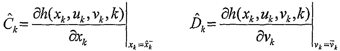
- At
step 80, thecomputer 28 determines a time interval that abattery 12 has been electrically decoupled from aload circuit 26. The time interval starts at a first time. - At
step 82, thecomputer 28 obtains a first state vector
battery 12 from thememory 46. The first state vector
- At
step 84, thecomputer 28 calculates a second predicted state vector
battery 12 based on the first state vector

- At
step 86, thecomputer 28 calculates a first covariance value


- At
step 88, thecomputer 28 induces thevoltage sensor 20 to measure a battery voltage output from thebattery 12 to obtain a first battery voltage value after the first time interval when thebattery 12 is electrically coupled to theload circuit 26. - At
step 90, thecomputer 28 estimates a second battery voltage value associated with thebattery 12 based on the second predicted state vector

- At
step 92, thecomputer 28 calculates a voltage error value based on the first battery voltage value and the second battery voltage value. - At
step 94, thecomputer 28 calculates a third predicted state vector
battery 12 based on the second predicted state vector


- At
step 96, thecomputer 28 calculates a second covariance value


step 96, the method is exited. - It should be noted that in alternate embodiments, the estimated state vector x̂k of the
battery 12 can be calculated utilizing a linear Kalman filter, a nonlinear sigma-point Kalman filter, a square-root linear Kalman filter, a square-root extended Kalman filter, a square-root sigma-point Kalman filter, a particle filter, and the like. - The system and methods for estimating a state vector associated with a battery provide a substantial advantage over other systems and methods. In particular, the system and methods provide a technical effect of accurately estimating a state vector associated with the battery at a time when a battery is electrically coupled to a load circuit, after it has been electrically decoupled from the load circuit for the time interval.
- The above-described methods can be embodied in the form of computer program code containing instructions embodied in tangible media, such as floppy diskettes, CD ROMs, hard drives, or any other computer-readable storage medium, wherein, when the computer program code is loaded into and executed by a computer, the computer becomes an apparatus for practicing the invention. The above-described methods can also be embodied in the form of computer program code, for example, whether stored in a storage medium, loaded into and/or executed by a computer, or transmitted over some transmission medium, loaded into and/or executed by a computer, or transmitted over some transmission medium, such as over electrical wiring or cabling, through fiber optics, or via electromagnetic radiation, wherein, when the computer program code is loaded into an executed by a computer, the computer becomes an apparatus for practicing the methods. When implemented on a general-purpose microprocessor, the computer program code segments configure the microprocessor to create specific logic circuits.
- While the invention is described with reference to the exemplary embodiments, it will be understood by those skilled in the art that various changes may be made an equivalence may be substituted for elements thereof without departing from the scope of the invention. In addition, many modifications may be made to the teachings of the invention to adapt to a particular situation without departing from the scope thereof. Therefore, is intended that the invention not be limited the embodiment disclosed for carrying out this invention, but that the invention includes all embodiments falling with the scope of the intended claims. Moreover, the use of the term's first, second, etc. does not denote any order of importance, but rather the term's first, second, etc. are used to distinguish one element from another.
Claims (8)
- (Currently Amended) A method for estimating a state vector associated with a battery, the method comprising the steps of:determining (60) a time interval that the battery has been electrically decoupled from a load circuit, the time interval starting at a first time;obtaining (62) a first state vector (x k-1) associated with the battery from a memory, the first state vector (x k-1) being determined prior to the first time;calculating (64) a second predicted state vector (
 measuring (68) a battery voltage output from the battery to obtain a first battery voltage value (yk ) after the first time interval when the battery is electrically re-coupled to the load circuit;estimating (70) a second battery voltage value (ŷk ) associated with the battery based on the second predicted state vector (
 calculating (72) a voltage error value based on the first battery voltage value and the second battery voltage value; andcalculating (74) a third estimated state vector

- The method of claim 1, further comprising calculating (76) a covariance value associated with the third estimated state vector.
- The method of claim 1, wherein the step of calculating the second predicted state vector comprises calculating the second predicted state vector associated with the battery based on the first state vector and the time interval utilizing at least one of a Kalman filter, an extended Kalman filter, a sigma-point Kalman filter, a square-root sigma-point Kalman filter, and a particle filter.
- The method of claim 1, wherein the step of calculating the third estimated state vector comprises calculating the third estimate state vector associated with the battery based on the second predicted state vector and the voltage error value utilizing at least one of a Kalman filter, an extended Kalman filter, a sigma-point Kalman filter, a square-root sigma-point Kalman filter, and a particle filter.
- The method of claim 1, wherein the second predicted state vector is indicative of at least a predicted state-of-charge of the battery.
- The method of claim 1, wherein the third predicted state vector is indicative of at least a predicted state-of-charge of the battery.
- A system (10) for estimating a state vector associated with a battery, the system comprising: a voltage sensor (20) configured to measure a voltage output from the battery; and a computer (28) operably coupled to the voltage sensor, the computer configured to implement the steps according to any of claims 1 to 6.
- A computer storage medium having a computer program encoded therein for estimating a state vector associated with a battery, the computer storage medium comprising a program implementing the method as claimed in any of claims 1 to 6.
Applications Claiming Priority (2)
| Application Number | Priority Date | Filing Date | Title |
|---|---|---|---|
| US11/209,453 US7589532B2 (en) | 2005-08-23 | 2005-08-23 | System and method for estimating a state vector associated with a battery |
| PCT/KR2006/003305 WO2007024093A1 (en) | 2005-08-23 | 2006-08-23 | System and method for estimating a state vector associated with a battery |
Publications (3)
| Publication Number | Publication Date |
|---|---|
| EP1917536A1 EP1917536A1 (en) | 2008-05-07 |
| EP1917536A4 EP1917536A4 (en) | 2017-08-23 |
| EP1917536B1 true EP1917536B1 (en) | 2018-08-08 |
Family
ID=37771801
Family Applications (1)
| Application Number | Title | Priority Date | Filing Date |
|---|---|---|---|
| EP06783700.5A Active EP1917536B1 (en) | 2005-08-23 | 2006-08-23 | System and method for estimating a state vector associated with a battery |
Country Status (7)
| Country | Link |
|---|---|
| US (2) | US7589532B2 (en) |
| EP (1) | EP1917536B1 (en) |
| JP (1) | JP4772871B2 (en) |
| KR (1) | KR100952049B1 (en) |
| CN (1) | CN101248365B (en) |
| TW (1) | TWI320610B (en) |
| WO (1) | WO2007024093A1 (en) |
Families Citing this family (60)
| Publication number | Priority date | Publication date | Assignee | Title |
|---|---|---|---|---|
| US7321220B2 (en) * | 2003-11-20 | 2008-01-22 | Lg Chem, Ltd. | Method for calculating power capability of battery packs using advanced cell model predictive techniques |
| US7723957B2 (en) * | 2005-11-30 | 2010-05-25 | Lg Chem, Ltd. | System, method, and article of manufacture for determining an estimated battery parameter vector |
| US8264203B2 (en) * | 2006-03-31 | 2012-09-11 | Valence Technology, Inc. | Monitoring state of charge of a battery |
| JP4703593B2 (en) * | 2007-03-23 | 2011-06-15 | 株式会社豊田中央研究所 | Secondary battery state estimation device |
| US8628872B2 (en) * | 2008-01-18 | 2014-01-14 | Lg Chem, Ltd. | Battery cell assembly and method for assembling the battery cell assembly |
| US7994755B2 (en) | 2008-01-30 | 2011-08-09 | Lg Chem, Ltd. | System, method, and article of manufacture for determining an estimated battery cell module state |
| US8067111B2 (en) * | 2008-06-30 | 2011-11-29 | Lg Chem, Ltd. | Battery module having battery cell assembly with heat exchanger |
| US7883793B2 (en) * | 2008-06-30 | 2011-02-08 | Lg Chem, Ltd. | Battery module having battery cell assemblies with alignment-coupling features |
| US9759495B2 (en) | 2008-06-30 | 2017-09-12 | Lg Chem, Ltd. | Battery cell assembly having heat exchanger with serpentine flow path |
| US8426050B2 (en) | 2008-06-30 | 2013-04-23 | Lg Chem, Ltd. | Battery module having cooling manifold and method for cooling battery module |
| US9140501B2 (en) * | 2008-06-30 | 2015-09-22 | Lg Chem, Ltd. | Battery module having a rubber cooling manifold |
| JP5073601B2 (en) * | 2008-07-10 | 2012-11-14 | 株式会社オートネットワーク技術研究所 | Battery state estimation method and power supply device |
| US8202645B2 (en) | 2008-10-06 | 2012-06-19 | Lg Chem, Ltd. | Battery cell assembly and method for assembling the battery cell assembly |
| US9337456B2 (en) | 2009-04-20 | 2016-05-10 | Lg Chem, Ltd. | Frame member, frame assembly and battery cell assembly made therefrom and methods of making the same |
| US8663829B2 (en) | 2009-04-30 | 2014-03-04 | Lg Chem, Ltd. | Battery systems, battery modules, and method for cooling a battery module |
| US8663828B2 (en) | 2009-04-30 | 2014-03-04 | Lg Chem, Ltd. | Battery systems, battery module, and method for cooling the battery module |
| US8403030B2 (en) | 2009-04-30 | 2013-03-26 | Lg Chem, Ltd. | Cooling manifold |
| US8852778B2 (en) | 2009-04-30 | 2014-10-07 | Lg Chem, Ltd. | Battery systems, battery modules, and method for cooling a battery module |
| US8399118B2 (en) * | 2009-07-29 | 2013-03-19 | Lg Chem, Ltd. | Battery module and method for cooling the battery module |
| US8703318B2 (en) * | 2009-07-29 | 2014-04-22 | Lg Chem, Ltd. | Battery module and method for cooling the battery module |
| US8399119B2 (en) * | 2009-08-28 | 2013-03-19 | Lg Chem, Ltd. | Battery module and method for cooling the battery module |
| US8427105B2 (en) * | 2009-12-02 | 2013-04-23 | Gregory L. Plett | System and method for equalizing a battery pack during a battery pack charging process |
| US8041522B2 (en) * | 2009-12-02 | 2011-10-18 | American Electric Vehicles, Ind. | System and method for recursively estimating battery cell total capacity |
| US8918299B2 (en) * | 2009-12-02 | 2014-12-23 | American Electric Vehicles, Inc. | System and method for maximizing a battery pack total energy metric |
| US10422824B1 (en) * | 2010-02-19 | 2019-09-24 | Nikola Llc | System and method for efficient adaptive joint estimation of battery cell state-of-charge, resistance, and available energy |
| US8341449B2 (en) | 2010-04-16 | 2012-12-25 | Lg Chem, Ltd. | Battery management system and method for transferring data within the battery management system |
| US9147916B2 (en) | 2010-04-17 | 2015-09-29 | Lg Chem, Ltd. | Battery cell assemblies |
| KR101215037B1 (en) | 2010-04-20 | 2012-12-24 | 에스티엘 테크놀로지 컴퍼니 리미티드 | Battery monitoring system |
| US8469404B2 (en) | 2010-08-23 | 2013-06-25 | Lg Chem, Ltd. | Connecting assembly |
| US8758922B2 (en) | 2010-08-23 | 2014-06-24 | Lg Chem, Ltd. | Battery system and manifold assembly with two manifold members removably coupled together |
| US8353315B2 (en) | 2010-08-23 | 2013-01-15 | Lg Chem, Ltd. | End cap |
| US8920956B2 (en) | 2010-08-23 | 2014-12-30 | Lg Chem, Ltd. | Battery system and manifold assembly having a manifold member and a connecting fitting |
| US9005799B2 (en) | 2010-08-25 | 2015-04-14 | Lg Chem, Ltd. | Battery module and methods for bonding cell terminals of battery cells together |
| US8662153B2 (en) | 2010-10-04 | 2014-03-04 | Lg Chem, Ltd. | Battery cell assembly, heat exchanger, and method for manufacturing the heat exchanger |
| KR101199978B1 (en) | 2011-02-09 | 2012-11-12 | 대양전기공업 주식회사 | Batterys state monitoring and power controls equipment |
| US8288031B1 (en) | 2011-03-28 | 2012-10-16 | Lg Chem, Ltd. | Battery disconnect unit and method of assembling the battery disconnect unit |
| US8449998B2 (en) | 2011-04-25 | 2013-05-28 | Lg Chem, Ltd. | Battery system and method for increasing an operational life of a battery cell |
| US9178192B2 (en) | 2011-05-13 | 2015-11-03 | Lg Chem, Ltd. | Battery module and method for manufacturing the battery module |
| CN102169168B (en) * | 2011-05-17 | 2013-04-24 | 杭州电子科技大学 | Battery dump energy estimation method based on particle filtering |
| US8974928B2 (en) | 2011-06-30 | 2015-03-10 | Lg Chem, Ltd. | Heating system for a battery module and method of heating the battery module |
| US8859119B2 (en) | 2011-06-30 | 2014-10-14 | Lg Chem, Ltd. | Heating system for a battery module and method of heating the battery module |
| US8993136B2 (en) | 2011-06-30 | 2015-03-31 | Lg Chem, Ltd. | Heating system for a battery module and method of heating the battery module |
| US8974929B2 (en) | 2011-06-30 | 2015-03-10 | Lg Chem, Ltd. | Heating system for a battery module and method of heating the battery module |
| US9496544B2 (en) | 2011-07-28 | 2016-11-15 | Lg Chem. Ltd. | Battery modules having interconnect members with vibration dampening portions |
| ITBO20110697A1 (en) * | 2011-12-07 | 2013-06-08 | Magneti Marelli Spa | ESTIMATION METHOD OF THE CAPACITY OF A STORAGE SYSTEM INCLUDING A NUMBER OF ELECTROCHEMICAL CELLS IN A HYBRID OR ELECTRIC TRACTION VEHICLE |
| US8922217B2 (en) * | 2012-05-08 | 2014-12-30 | GM Global Technology Operations LLC | Battery state-of-charge observer |
| CN103033761B (en) * | 2012-12-17 | 2014-12-10 | 哈尔滨工业大学 | Lithium ion battery residual life forecasting method of dynamic gray related vector machine |
| JP6168813B2 (en) * | 2013-03-29 | 2017-07-26 | 株式会社ケーヒン | Voltage detector |
| KR101650415B1 (en) | 2013-10-14 | 2016-08-23 | 주식회사 엘지화학 | Apparatus for estimating voltage of hybrid secondary battery and Method thereof |
| KR101708885B1 (en) | 2013-10-14 | 2017-02-21 | 주식회사 엘지화학 | Apparatus for estimating state of secondary battery including blended cathode material and Method thereof |
| WO2015056964A1 (en) * | 2013-10-14 | 2015-04-23 | 주식회사 엘지화학 | Apparatus for estimating state of hybrid secondary battery and method therefor |
| WO2015056963A1 (en) * | 2013-10-14 | 2015-04-23 | 주식회사 엘지화학 | Apparatus for estimating state of secondary battery including blended positive electrode material, and method therefor |
| KR101632351B1 (en) | 2013-10-14 | 2016-06-21 | 주식회사 엘지화학 | Apparatus for estimating state of hybrid secondary battery and Method thereof |
| WO2015056962A1 (en) * | 2013-10-14 | 2015-04-23 | 주식회사 엘지화학 | Apparatus for estimating voltage of hybrid secondary battery and method therefor |
| US9381823B2 (en) * | 2014-07-17 | 2016-07-05 | Ford Global Technologies, Llc | Real-time battery estimation |
| KR101798201B1 (en) | 2014-10-01 | 2017-11-15 | 주식회사 엘지화학 | Method and Apparatus for estimating discharge power of secondary battery |
| FR3029315B1 (en) * | 2014-11-28 | 2016-12-09 | Renault Sa | AUTOMATIC METHOD OF ESTIMATING THE CAPACITY OF A CELL OF A BATTERY |
| KR101846642B1 (en) | 2015-02-02 | 2018-04-06 | 주식회사 엘지화학 | Method for determining resistance factor of secondary battery, and Apparatus and Method for estimating charging power of secondary battery using determined resistance factor |
| US9846110B2 (en) * | 2015-06-02 | 2017-12-19 | GM Global Technology Operations LLC | Particulate matter sensor diagnostic system and method |
| CN112965001B (en) * | 2021-02-09 | 2024-06-21 | 重庆大学 | A power battery pack fault diagnosis method based on real vehicle data |
Family Cites Families (17)
| Publication number | Priority date | Publication date | Assignee | Title |
|---|---|---|---|---|
| JP3262253B2 (en) * | 1995-02-22 | 2002-03-04 | 株式会社日立製作所 | Drive control device and control method for electric vehicle |
| US5694335A (en) * | 1996-03-12 | 1997-12-02 | Hollenberg; Dennis D. | Secure personal applications network |
| US7688074B2 (en) * | 1997-11-03 | 2010-03-30 | Midtronics, Inc. | Energy management system for automotive vehicle |
| CN1199050C (en) * | 1998-05-28 | 2005-04-27 | 丰田自动车株式会社 | Means for estimating charged state of battery and method for estimating degraded state of battery |
| JPH11346444A (en) * | 1998-06-02 | 1999-12-14 | Toyota Motor Corp | Method of estimating battery charge state |
| DE19960761C1 (en) * | 1999-12-16 | 2001-05-23 | Daimler Chrysler Ag | Battery residual charge monitoring method uses difference between minimum current and current at intersection point between current/voltage curve and minimum voltage threshold of battery |
| JP2001272444A (en) * | 2000-03-27 | 2001-10-05 | Hitachi Maxell Ltd | Remaining battery capacity estimation device |
| EP1160953B1 (en) * | 2000-05-29 | 2009-12-02 | Panasonic Corporation | Method for charging battery |
| US6441586B1 (en) * | 2001-03-23 | 2002-08-27 | General Motors Corporation | State of charge prediction method and apparatus for a battery |
| US6876175B2 (en) * | 2001-06-29 | 2005-04-05 | Robert Bosch Gmbh | Methods for determining the charge state and/or the power capacity of charge store |
| FI114048B (en) * | 2001-12-03 | 2004-07-30 | Teknillinen Korkeakoulu | Method and apparatus for utilizing programmed meters to characterize accumulators |
| US6727708B1 (en) * | 2001-12-06 | 2004-04-27 | Johnson Controls Technology Company | Battery monitoring system |
| US6534954B1 (en) | 2002-01-10 | 2003-03-18 | Compact Power Inc. | Method and apparatus for a battery state of charge estimator |
| US6927554B2 (en) | 2003-08-28 | 2005-08-09 | General Motors Corporation | Simple optimal estimator for PbA state of charge |
| US20050100786A1 (en) | 2003-09-19 | 2005-05-12 | Ryu Duk H. | Nonaqueous lithium secondary battery with cyclability and/or high temperature safety improved |
| US20050127874A1 (en) | 2003-12-12 | 2005-06-16 | Myoungho Lim | Method and apparatus for multiple battery cell management |
| US7212006B2 (en) * | 2004-07-02 | 2007-05-01 | Bppower, Inc. | Method and apparatus for monitoring the condition of a battery by measuring its internal resistance |
-
2005
- 2005-08-23 US US11/209,453 patent/US7589532B2/en active Active
-
2006
- 2006-08-23 EP EP06783700.5A patent/EP1917536B1/en active Active
- 2006-08-23 KR KR1020087006165A patent/KR100952049B1/en active Active
- 2006-08-23 TW TW095130978A patent/TWI320610B/en active
- 2006-08-23 CN CN2006800308815A patent/CN101248365B/en active Active
- 2006-08-23 WO PCT/KR2006/003305 patent/WO2007024093A1/en not_active Ceased
- 2006-08-23 JP JP2008527845A patent/JP4772871B2/en active Active
-
2009
- 2009-06-29 US US12/493,787 patent/US7800375B2/en not_active Expired - Lifetime
Non-Patent Citations (1)
| Title |
|---|
| None * |
Also Published As
| Publication number | Publication date |
|---|---|
| KR100952049B1 (en) | 2010-04-07 |
| US20090261837A1 (en) | 2009-10-22 |
| EP1917536A4 (en) | 2017-08-23 |
| TWI320610B (en) | 2010-02-11 |
| EP1917536A1 (en) | 2008-05-07 |
| CN101248365A (en) | 2008-08-20 |
| JP4772871B2 (en) | 2011-09-14 |
| JP2009506317A (en) | 2009-02-12 |
| US7589532B2 (en) | 2009-09-15 |
| US7800375B2 (en) | 2010-09-21 |
| KR20080041702A (en) | 2008-05-13 |
| WO2007024093A1 (en) | 2007-03-01 |
| CN101248365B (en) | 2010-11-10 |
| US20070046292A1 (en) | 2007-03-01 |
| TW200711210A (en) | 2007-03-16 |
Similar Documents
| Publication | Publication Date | Title |
|---|---|---|
| EP1917536B1 (en) | System and method for estimating a state vector associated with a battery | |
| US7400115B2 (en) | System, method, and article of manufacture for determining an estimated combined battery state-parameter vector | |
| US7521895B2 (en) | System and method for determining both an estimated battery state vector and an estimated battery parameter vector | |
| EP1971872B1 (en) | System, method, and article of manufacture for determining an estimated battery parameter vector | |
| EP1949523B1 (en) | System, method, and article of manufacture for determining an estimated battery state vector | |
| US8103485B2 (en) | State and parameter estimation for an electrochemical cell | |
| US7593821B2 (en) | Method and system for joint battery state and parameter estimation | |
| US6534954B1 (en) | Method and apparatus for a battery state of charge estimator |
Legal Events
| Date | Code | Title | Description |
|---|---|---|---|
| PUAI | Public reference made under article 153(3) epc to a published international application that has entered the european phase |
Free format text: ORIGINAL CODE: 0009012 |
|
| 17P | Request for examination filed |
Effective date: 20080204 |
|
| AK | Designated contracting states |
Kind code of ref document: A1 Designated state(s): DE FR GB IT |
|
| DAX | Request for extension of the european patent (deleted) | ||
| RBV | Designated contracting states (corrected) |
Designated state(s): DE FR GB IT |
|
| RA4 | Supplementary search report drawn up and despatched (corrected) |
Effective date: 20170724 |
|
| RIC1 | Information provided on ipc code assigned before grant |
Ipc: G01R 31/36 20060101AFI20170718BHEP |
|
| GRAP | Despatch of communication of intention to grant a patent |
Free format text: ORIGINAL CODE: EPIDOSNIGR1 |
|
| STAA | Information on the status of an ep patent application or granted ep patent |
Free format text: STATUS: GRANT OF PATENT IS INTENDED |
|
| INTG | Intention to grant announced |
Effective date: 20180316 |
|
| GRAS | Grant fee paid |
Free format text: ORIGINAL CODE: EPIDOSNIGR3 |
|
| GRAA | (expected) grant |
Free format text: ORIGINAL CODE: 0009210 |
|
| STAA | Information on the status of an ep patent application or granted ep patent |
Free format text: STATUS: THE PATENT HAS BEEN GRANTED |
|
| AK | Designated contracting states |
Kind code of ref document: B1 Designated state(s): DE FR GB IT |
|
| REG | Reference to a national code |
Ref country code: GB Ref legal event code: FG4D |
|
| REG | Reference to a national code |
Ref country code: FR Ref legal event code: PLFP Year of fee payment: 13 |
|
| REG | Reference to a national code |
Ref country code: DE Ref legal event code: R096 Ref document number: 602006056048 Country of ref document: DE |
|
| RAP2 | Party data changed (patent owner data changed or rights of a patent transferred) |
Owner name: LG CHEM, LTD. |
|
| PG25 | Lapsed in a contracting state [announced via postgrant information from national office to epo] |
Ref country code: IT Free format text: LAPSE BECAUSE OF FAILURE TO SUBMIT A TRANSLATION OF THE DESCRIPTION OR TO PAY THE FEE WITHIN THE PRESCRIBED TIME-LIMIT Effective date: 20180808 |
|
| REG | Reference to a national code |
Ref country code: DE Ref legal event code: R097 Ref document number: 602006056048 Country of ref document: DE |
|
| PLBE | No opposition filed within time limit |
Free format text: ORIGINAL CODE: 0009261 |
|
| STAA | Information on the status of an ep patent application or granted ep patent |
Free format text: STATUS: NO OPPOSITION FILED WITHIN TIME LIMIT |
|
| 26N | No opposition filed |
Effective date: 20190509 |
|
| P01 | Opt-out of the competence of the unified patent court (upc) registered |
Effective date: 20230512 |
|
| REG | Reference to a national code |
Ref country code: DE Ref legal event code: R081 Ref document number: 602006056048 Country of ref document: DE Owner name: LG ENERGY SOLUTION, LTD., KR Free format text: FORMER OWNER: LG CHEM, LTD., SEOUL, KR |
|
| REG | Reference to a national code |
Ref country code: GB Ref legal event code: 732E Free format text: REGISTERED BETWEEN 20230824 AND 20230831 |
|
| PGFP | Annual fee paid to national office [announced via postgrant information from national office to epo] |
Ref country code: DE Payment date: 20250721 Year of fee payment: 20 |
|
| PGFP | Annual fee paid to national office [announced via postgrant information from national office to epo] |
Ref country code: GB Payment date: 20250722 Year of fee payment: 20 |
|
| PGFP | Annual fee paid to national office [announced via postgrant information from national office to epo] |
Ref country code: FR Payment date: 20250725 Year of fee payment: 20 |