EP2108842A1 - Scroll compressor - Google Patents
Scroll compressor Download PDFInfo
- Publication number
- EP2108842A1 EP2108842A1 EP07707679A EP07707679A EP2108842A1 EP 2108842 A1 EP2108842 A1 EP 2108842A1 EP 07707679 A EP07707679 A EP 07707679A EP 07707679 A EP07707679 A EP 07707679A EP 2108842 A1 EP2108842 A1 EP 2108842A1
- Authority
- EP
- European Patent Office
- Prior art keywords
- scroll
- lubricant
- scroll compressor
- wall
- spiral
- Prior art date
- Legal status (The legal status is an assumption and is not a legal conclusion. Google has not performed a legal analysis and makes no representation as to the accuracy of the status listed.)
- Granted
Links
Images


Classifications
-
- F—MECHANICAL ENGINEERING; LIGHTING; HEATING; WEAPONS; BLASTING
- F04—POSITIVE - DISPLACEMENT MACHINES FOR LIQUIDS; PUMPS FOR LIQUIDS OR ELASTIC FLUIDS
- F04C—ROTARY-PISTON, OR OSCILLATING-PISTON, POSITIVE-DISPLACEMENT MACHINES FOR LIQUIDS; ROTARY-PISTON, OR OSCILLATING-PISTON, POSITIVE-DISPLACEMENT PUMPS
- F04C18/00—Rotary-piston pumps specially adapted for elastic fluids
- F04C18/02—Rotary-piston pumps specially adapted for elastic fluids of arcuate-engagement type, i.e. with circular translatory movement of co-operating members, each member having the same number of teeth or tooth-equivalents
- F04C18/0207—Rotary-piston pumps specially adapted for elastic fluids of arcuate-engagement type, i.e. with circular translatory movement of co-operating members, each member having the same number of teeth or tooth-equivalents both members having co-operating elements in spiral form
- F04C18/0215—Rotary-piston pumps specially adapted for elastic fluids of arcuate-engagement type, i.e. with circular translatory movement of co-operating members, each member having the same number of teeth or tooth-equivalents both members having co-operating elements in spiral form where only one member is moving
-
- F—MECHANICAL ENGINEERING; LIGHTING; HEATING; WEAPONS; BLASTING
- F04—POSITIVE - DISPLACEMENT MACHINES FOR LIQUIDS; PUMPS FOR LIQUIDS OR ELASTIC FLUIDS
- F04C—ROTARY-PISTON, OR OSCILLATING-PISTON, POSITIVE-DISPLACEMENT MACHINES FOR LIQUIDS; ROTARY-PISTON, OR OSCILLATING-PISTON, POSITIVE-DISPLACEMENT PUMPS
- F04C18/00—Rotary-piston pumps specially adapted for elastic fluids
- F04C18/02—Rotary-piston pumps specially adapted for elastic fluids of arcuate-engagement type, i.e. with circular translatory movement of co-operating members, each member having the same number of teeth or tooth-equivalents
- F04C18/0207—Rotary-piston pumps specially adapted for elastic fluids of arcuate-engagement type, i.e. with circular translatory movement of co-operating members, each member having the same number of teeth or tooth-equivalents both members having co-operating elements in spiral form
- F04C18/0246—Details concerning the involute wraps or their base, e.g. geometry
- F04C18/0269—Details concerning the involute wraps
- F04C18/0276—Different wall heights
-
- F—MECHANICAL ENGINEERING; LIGHTING; HEATING; WEAPONS; BLASTING
- F04—POSITIVE - DISPLACEMENT MACHINES FOR LIQUIDS; PUMPS FOR LIQUIDS OR ELASTIC FLUIDS
- F04C—ROTARY-PISTON, OR OSCILLATING-PISTON, POSITIVE-DISPLACEMENT MACHINES FOR LIQUIDS; ROTARY-PISTON, OR OSCILLATING-PISTON, POSITIVE-DISPLACEMENT PUMPS
- F04C18/00—Rotary-piston pumps specially adapted for elastic fluids
- F04C18/08—Rotary-piston pumps specially adapted for elastic fluids of intermeshing-engagement type, i.e. with engagement of co-operating members similar to that of toothed gearing
- F04C18/082—Details specially related to intermeshing engagement type pumps
- F04C18/088—Elements in the toothed wheels or the carter for relieving the pressure of fluid imprisoned in the zones of engagement
-
- F—MECHANICAL ENGINEERING; LIGHTING; HEATING; WEAPONS; BLASTING
- F04—POSITIVE - DISPLACEMENT MACHINES FOR LIQUIDS; PUMPS FOR LIQUIDS OR ELASTIC FLUIDS
- F04C—ROTARY-PISTON, OR OSCILLATING-PISTON, POSITIVE-DISPLACEMENT MACHINES FOR LIQUIDS; ROTARY-PISTON, OR OSCILLATING-PISTON, POSITIVE-DISPLACEMENT PUMPS
- F04C29/00—Component parts, details or accessories of pumps or pumping installations, not provided for in groups F04C18/00 - F04C28/00
- F04C29/02—Lubrication; Lubricant separation
- F04C29/028—Means for improving or restricting lubricant flow
Definitions
- the present invention relates to scroll compressors used for air conditioners, refrigerators, and the like.
- a fixed scroll and an orbiting scroll are arranged with their spiral walls being assembled, and the orbiting scroll is made to orbitally revolve around the fixed scroll to gradually reduce the volume of compression spaces formed between the walls, thereby compressing fluid in the compression spaces.
- those that employ scroll members having stepped shapes have been put to practical use because the compression ratio can be increased without increasing the size of the compressors themselves, so as to improve the compression performance.
- a tip seal is provided along a connection edge that connects, at a step portion, the upper edges having different heights, in order to improve the airtightness between the scrolls to improve the compression performance, and which has a mechanism that prevents the tip seal from being removed from the connection edge.
- Patent Document 1 Japanese Unexamined Patent Application, Publication No. 2002-303281
- a minute gap is formed between the fixed scroll and the orbiting scroll to allow the orbiting operation of the orbiting scroll. Therefore, when the volume of the compression spaces is gradually reduced as the compression process proceeds, compressed gas leaks from the high-pressure side to the low-pressure side through the minute gap. Accordingly, the minute gap formed at the step portion causes a reduction in the compression efficiency of the scroll compressor.
- recent high-pressure refrigerant for example, R410A, CO 2 , or the like
- the difference in pressure between the high-pressure side and the low-pressure side is increased, so that the leakage of compressed gas causes a more significant reduction in efficiency.
- the present invention has been made in view of the circumstances described above, and an object thereof is to provide a scroll compressor in which the cylinder oil lubrication rate of lubricant during the operation is optimized to improve the compression efficiency.
- a scroll compressor including: a fixed scroll which has a spiral wall formed upright on one side face of an end plate; and an orbiting scroll which has a spiral wall formed upright on one side face of an end plate and which is supported, when the walls are engaged, so as to allow orbital revolving motion thereof while preventing rotation thereof, the one side face of the end plate of at least one of the fixed scroll and the orbiting scroll being provided with a step part formed to be higher at a center portion and lower at an outer end along a spiral of the wall, an upper edge of the wall of the other one of the fixed scroll and the orbiting scroll being divided into a plurality of portions whose height is low at a center portion of a spiral and is high at an outer end of the spiral, to form a stepped shape corresponding to the step part provided on the end plate, in which a cylinder oil circulation rate of lubricant taken into the scroll compressor and circulated together with refrigerant
- the cylinder oil circulation rate of lubricant taken into the compressor and circulated together with refrigerant is set to fall within the range from 1% or more to 10% or less. Therefore, a sufficient amount of lubricant to form an oil film to seal a minute gap at the step part can be provided.
- the lubricant be supplied to the vicinity of the step part.
- this structure it is possible to provide a sufficient amount of lubricant for the vicinity of the step part and to form an oil film effective to seal the minute gap.
- the lubricant be supplied to the vicinity of the step part located higher in the direction of gravitational force when the fixed scroll and the orbiting scroll are of a horizontal type. With this structure, the lubricant can fall under the influence of the gravitational force to be supplied.
- the cylinder oil circulation rate of lubricant is set to fall within the range from 1% or more to 10% or less, it is possible to provide a sufficient amount of lubricant to form an oil film to seal the minute gap at the step part and to improve the sealing properties of the minute gap at the step part.
- a significant advantageous effect can be obtained in that the amount of compressed gas leaking from the minute gap at the step part is reduced, thereby improving the compression efficiency of the scroll compressor having the stepped shape.
- FIG. 3 is a cross-sectional view showing an example configuration of a scroll compressor CP.
- reference numeral 1 is a hermetically-sealed housing
- 2 is a discharge cover which divides the housing 1 into a high-pressure chamber HR and a low-pressure chamber LR
- 5 is a frame
- 6 is an inlet pipe
- 7 is an outlet pipe
- 8 is a motor
- 9 is a rotary shaft
- 10 is a rotation preventing mechanism.
- Reference numeral 12 is a fixed scroll
- 13 is an orbiting scroll engaged with the fixed scroll 12.
- the fixed scroll 12 is provided with a spiral wall 12b formed upright on one side face of an end plate 12a, as shown in FIG. 4A .
- the orbiting scroll 13 is provided with a spiral wall 13b formed upright on one side face of an end plate 13a, as shown in FIG. 4B .
- the wall 13b has substantially the same shape as the wall 12b of the fixed scroll 12. The walls 12b and 13b are engaged and assembled such that the orbiting scroll 13 is eccentric relative to the fixed scroll 12 by the radius of orbital revolution and their phases are shifted from each other by 180 degrees.
- the orbiting scroll 13 performs orbital revolving motion with respect to the fixed scroll 12, due to the actions of the rotation preventing mechanism 10 and an eccentric pin 9a that is provided on the top of the rotary shaft 9 driven by the motor 8 and that performs orbiting motion.
- the fixed scroll 12 is fixed to the housing 1, and an outlet port 11 for compressed fluid is provided at the center of the rear face of the end plate 12a.
- a step part 42 is formed to be higher at a center portion and lower at an outer end along the spiral wall 12b.
- a step part 43 is formed to be higher at a center portion and lower at an outer end along the spiral wall 13b.
- the step parts 42 and 43 are provided starting at locations that are n (rad) away from the outer ends (inlet sides) of the walls 12b and 13b toward the inner ends (outlet sides) thereof, respectively, with the centers of the spiral walls 12b and 13b serving as reference points.
- a bottom face of the end plate 12a is divided into two portions, that is, a shallow bottom face 12f provided nearer the center portion and a deep bottom face 12g provided nearer the outer end. Between the adjacent bottom faces 12f and 12g, there is a connecting wall face 12h which constitutes the step part 42 and vertically rises to connect the bottom faces 12f and 12g.
- a bottom face of the end plate 13a is divided into two portions, that is, a shallow bottom face 13f provided nearer the center portion and a deep bottom face 13g provided nearer the outer end. Between the adjacent bottom faces 13f and 13g, there is a connecting wall face 13h which constitutes the step part 43 and vertically rises to connect the bottom faces 13f and 13g.
- the spiral upper edge of the wall 12b of the fixed scroll 12 is divided into two portions which are low at the center portion of the spiral and high at the outer end of the spiral, thereby forming a stepped shape corresponding to the step part 43 of the orbiting scroll 13.
- the spiral upper edge of the wall 13b of the orbiting scroll 13 is divided into two portions which are low at the center portion of the spiral and high at the outer end of the spiral, thereby forming a stepped shape corresponding to the step part 42 of the fixed scroll 12.
- the upper edge of the wall 12b is divided into two portions, that is, a low-level upper edge 12c provided nearer the center portion and a high-level upper edge 12d provided nearer the outer end.
- the upper edge of the wall 13b is divided into two portions, that is, a low-level upper edge 13c provided nearer the center portion and a high-level upper edge 13d provided nearer the outer end. Between the adjacent upper edges 13c and 13d, there is a connecting edge 13e which connects them and is perpendicular to the orbit plane.
- the connecting edge 12e When the wall 12b is viewed from the orbiting scroll 13, the connecting edge 12e has a semicircular shape which is smoothly connected to both inner and outer side faces of the wall 12b and whose diameter is the same as the thickness of the wall 12b. Similarly to the connecting edge 12e, the connecting edge 13e has a semicircular shape which is smoothly connected to both inner and outer side faces of the wall 13b and whose diameter is the same as the thickness of the wall 13b.
- the connecting wall face 12h When the end plate 12a is viewed from the direction of an orbit axis, the connecting wall face 12h has an arc that matches an envelope curve traced by the connecting edge 13e during the orbit of the orbiting scroll. Similarly to the connecting wall face 12h, the connecting wall face 13h has an arc that matches an envelope curve traced by the connecting edge 12e.
- Tip seals 14a and 14b which are separated from each other in the vicinity of the connecting edge 12e are respectively provided on the upper edges 12c and 12d of the wall 12b of the fixed scroll 12.
- tip seals 15a and 15b which are separated from each other in the vicinity of the connecting edge 13e are respectively provided on the upper edges 13c and 13d of the wall 13b of the orbiting scroll 13.
- Those tip seals are used to seal tip seal gaps formed between the upper edges (tips) and the bottom faces (bottoms), between the orbiting scroll 12 and the fixed scroll 13, thereby minimizing the leakage of compressed gas fluid.
- FIG. 4A shows the fixed scroll 12 placed upside down in order to show the stepped shape of the fixed scroll 12.
- FIG. 5 shows a state where the fixed scroll 12 and the orbiting scroll 13 are assembled to form the compression spaces C and are about to start compression.
- this compression start state the outer end of the wall 12b is brought into contact with the outer side face of the wall 13b, the outer end of the wall 13b is brought into contact with the outer side face of the wall 12b, fluid to be compressed is sealed between the end plates 12a and 13a and between the walls 12b and 13b, and the two compression spaces C, each having the maximum volume, are formed at locations that face each other across the center of the scroll compression mechanism.
- connecting edge 12e and the connecting wall face 13h, and the connecting edge 13e and the connecting wall face 12h are brought into contact with each other in a slidable manner at this time, they are immediately separated from each other by the orbiting operation of the orbiting scroll 12.
- the cylinder oil circulation rate (hereinafter also referred to as "OC%") of lubricant taken into the scroll compressor CP and circulated together with refrigerant is set to fall within the range from 1% or more to 10% or less.
- the lubricant is supplied to each sliding part in the scroll compressor CP for lubrication, and at least part of the lubricant is converted into mist lubricant and compressed together with gas refrigerant. Therefore, the mist lubricant flows out from the scroll compression mechanism together with the gas refrigerant.
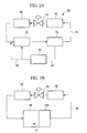
- an oil separator 51 is provided in a refrigerant circuit 50 shown in FIG. 2 , for example.
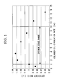
- FIG. 1 is a graph of experimental results, showing how the efficiency of the scroll compressor CP changes when the cylinder oil circulation rate (%) is changed.
- the horizontal axis indicates the cylinder oil circulation rate and the vertical axis indicates the efficiency ratio.
- the efficiency is improved when the efficiency ratio is increased to 1 or more.
- the efficiency ratio used in this case is calculated by using, as a reference (denominator), the efficiency of a conventional scroll compressor that has an identical volume but does not employ the stepped shape, and using the efficiency obtained as a result of each experiment as a numerator. From the experimental results, it is found that the efficiency ratio is 1 or more when the cylinder oil circulation rate falls within the range from 1% to 10%.
- the efficiency ratio is increased as the cylinder oil lubrication rate is increased.
- the efficiency ratio tends to be reduced.
- the efficiency ratio returns to 1. Therefore, it is preferable that the cylinder oil circulation rate fall within an optimum usage range of 1% or more to 10% or less. It is more preferable that the cylinder oil circulation rate fall within a range of 1% or more to 3.5% or less, where the efficiency can be improved with the minimum circulation amount.
- reference numeral 51 in the figure is the oil separator
- 52 is a condenser
- 53 is a throttling mechanism
- 54 is an evaporator.
- High-temperature and high-pressure gas refrigerant discharged from the scroll compressor CP circulates through a refrigerant pipe 55 to be condensed and evaporated, thereby undergoing repeated changes in state.
- reference numeral 60 is a flow-rate adjustment device provided on a lubricant supply pipe 56 to adjust the amount of lubricant to be returned from the oil separator 51 to the scroll compressor CP.
- gas refrigerant supplied to the condenser 52 exchanges heat with surrounding air or the like to radiate heat
- liquid refrigerant supplied to the evaporator 54 exchanges heat with surrounding air or the like to absorb heat.
- the oil separator 51 is externally attached at a location near the outlet side of the scroll compressor CP and upstream of the condenser 52.
- the oil separator 51 which is externally attached, it is possible to use a built-in oil separator 51A that is built into the scroll compressor CP in the flow path at the outlet side of the scroll compressor CP, as in a refrigerant circuit 50A shown in FIG. 2B , for example.
- Each of the above-described oil separators 51 and 51A separates mist lubricant from gas refrigerant discharged from the scroll compressor CP, stores the lubricant, and supplies the lubricant in a necessary amount controlled, for example, by the flow-rate adjustment device 60 to an appropriate portion of the scroll compressor CP by using a lubricant pump mechanism or the like (not shown).
- a lubricant pump mechanism or the like not shown.
- the oil separator 51 and the housing 51 of the scroll compressor CP are coupled by the lubricant supply pipe 56, and the oil separator 51 and the intake pipe are coupled by a lubricant supply pipe 56'.
- the lubricant is supplied particularly to the vicinity of the step parts 42 and 43, an abundant amount of lubricant can be provided near the minute gaps, thereby reliably forming good oil films having excellent sealing properties.
- the lubricant supply passages 57 are formed inside the wall 12b of the fixed scroll 12 to supply lubricant to the vicinity of the step part.
- the lubricant supply passages 57 are communicated with outlet holes 58 which are opened to the connecting edge 12e and to the low-level upper edge 12c connected to the connecting edge 12e, to let lubricant flow out from both of the outlet holes 58.
- reference numeral 59 is a minute groove which holds the lubricant.
- the scroll compressor CP When the scroll compressor CP is of a horizontal type, if lubricant is supplied to the vicinity of one step part, located higher in the direction of gravitational force, of the step parts 42 and 43, a sufficient amount of lubricant can be provided for the other step part, located lower in the direction of gravitational force, because the lubricant falls due to the gravitational force. Therefore, oil films that are effective in sealing the minute gaps can be efficiently formed in both step parts, located higher and lower in the direction of gravitational force, and the oil films can prevent leakage, thus improving the efficiency of the scroll compressor CP.
- the above-described cylinder oil circulation rate may be set through lubricant flow-rate control performed by using, for example, the flow-rate adjustment device 60, to be described below.
- the flow-rate adjustment device 60 is located between the scroll compressor CP, which compresses and discharges refrigerant, and the oil separator 51, which separates mist lubricant included in the refrigerant discharged from the scroll compressor CP.
- the flow-rate adjustment device 60 has a function of increasing a flow rate of lubricant to be returned from the oil separator 51 to the scroll compressor CP as a refrigerant-circulation-amount parameter is increased.
- the refrigerant-circulation-amount parameter is a control value expressed by the product of the rotational speed of the scroll compressor CP and the pressure of refrigerant measured at the inlet of the scroll compressor CP.
- the flow rate of lubricant means the amount of lubricant to be returned to the scroll compressor CP per unit time or the amount of lubricant to be returned to the scroll compressor CP within a predetermined period of time.
- lubricant flows in a continuous manner, either the amount of lubricant to be returned to the scroll compressor CP per unit time or the amount of lubricant to be returned to the scroll compressor CP within a predetermined period of time may be used for comparison of the amount of lubricant to be returned to the scroll compressor CP.
- the cylinder oil circulation rate (OC%) of lubricant is set to fall within the range from 1% or more to 10% or less, it is possible to provide a sufficient amount of lubricant to form oil films to seal the minute gaps at the step parts 42 and 43, and to improve the sealing properties of the minute gaps at the step parts 42 and 43. As a result, the amount of compressed gas leaking from the minute gaps at the step parts 42 and 43 can be reduced, thereby improving the compression efficiency of the scroll compressor CP having the stepped shape.
- the present invention is not limited to the embodiment described above.
- the present invention can be applied to any types of compressors, such as horizontal compressors, vertical compressors, hermetic type compressors, and open type compressors, as long as the compressors have a scroll compression mechanism having a stepped shape. Modifications can be appropriately made without departing from the scope of the present invention.
Landscapes
- Engineering & Computer Science (AREA)
- Mechanical Engineering (AREA)
- General Engineering & Computer Science (AREA)
- Rotary Pumps (AREA)
Abstract
Description
- The present invention relates to scroll compressors used for air conditioners, refrigerators, and the like.
- In scroll compressors, a fixed scroll and an orbiting scroll are arranged with their spiral walls being assembled, and the orbiting scroll is made to orbitally revolve around the fixed scroll to gradually reduce the volume of compression spaces formed between the walls, thereby compressing fluid in the compression spaces. Among such scroll compressors, those that employ scroll members having stepped shapes have been put to practical use because the compression ratio can be increased without increasing the size of the compressors themselves, so as to improve the compression performance. In one such scroll compressor that has been proposed a tip seal is provided along a connection edge that connects, at a step portion, the upper edges having different heights, in order to improve the airtightness between the scrolls to improve the compression performance, and which has a mechanism that prevents the tip seal from being removed from the connection edge. (For example, see
Patent Document 1.) - Patent Document 1: Japanese Unexamined Patent Application, Publication No.
2002-303281 - At the step portion of each of the scroll members described above, a minute gap is formed between the fixed scroll and the orbiting scroll to allow the orbiting operation of the orbiting scroll. Therefore, when the volume of the compression spaces is gradually reduced as the compression process proceeds, compressed gas leaks from the high-pressure side to the low-pressure side through the minute gap. Accordingly, the minute gap formed at the step portion causes a reduction in the compression efficiency of the scroll compressor. In particular, when recent high-pressure refrigerant (for example, R410A, CO2, or the like) is used, the difference in pressure between the high-pressure side and the low-pressure side is increased, so that the leakage of compressed gas causes a more significant reduction in efficiency.
- From such circumstances, it is demanded that the minute gap at the step portion be sealed with an oil film of lubricant which is taken into and circulated in the scroll compressor when the scroll compressor is operated, to reduce the leakage of compressed gas and improve the compression efficiency.
The present invention has been made in view of the circumstances described above, and an object thereof is to provide a scroll compressor in which the cylinder oil lubrication rate of lubricant during the operation is optimized to improve the compression efficiency. - In order to solve the problems described above, the present invention employs the following solutions.
According to the present invention, there is provided a scroll compressor including: a fixed scroll which has a spiral wall formed upright on one side face of an end plate; and an orbiting scroll which has a spiral wall formed upright on one side face of an end plate and which is supported, when the walls are engaged, so as to allow orbital revolving motion thereof while preventing rotation thereof, the one side face of the end plate of at least one of the fixed scroll and the orbiting scroll being provided with a step part formed to be higher at a center portion and lower at an outer end along a spiral of the wall, an upper edge of the wall of the other one of the fixed scroll and the orbiting scroll being divided into a plurality of portions whose height is low at a center portion of a spiral and is high at an outer end of the spiral, to form a stepped shape corresponding to the step part provided on the end plate, in which a cylinder oil circulation rate of lubricant taken into the scroll compressor and circulated together with refrigerant is set to fall within the range from 1% or more to 10% or less. - According to this scroll compressor, the cylinder oil circulation rate of lubricant taken into the compressor and circulated together with refrigerant is set to fall within the range from 1% or more to 10% or less. Therefore, a sufficient amount of lubricant to form an oil film to seal a minute gap at the step part can be provided.
- In the above-described scroll compressor, it is preferable that the lubricant be supplied to the vicinity of the step part. With this structure, it is possible to provide a sufficient amount of lubricant for the vicinity of the step part and to form an oil film effective to seal the minute gap.
- In the above-described scroll compressor, it is preferable that the lubricant be supplied to the vicinity of the step part located higher in the direction of gravitational force when the fixed scroll and the orbiting scroll are of a horizontal type. With this structure, the lubricant can fall under the influence of the gravitational force to be supplied.
- According to the aspect described above, since the cylinder oil circulation rate of lubricant is set to fall within the range from 1% or more to 10% or less, it is possible to provide a sufficient amount of lubricant to form an oil film to seal the minute gap at the step part and to improve the sealing properties of the minute gap at the step part. As a result, a significant advantageous effect can be obtained in that the amount of compressed gas leaking from the minute gap at the step part is reduced, thereby improving the compression efficiency of the scroll compressor having the stepped shape.
-
- [
FIG. 1] FIG. 1 is a graph of experimental results, showing how the efficiency of a scroll compressor according to an embodiment of the present invention changes when a cylinder oil circulation rate (%) is changed. - [
FIG. 2A] FIG. 2A is a circuit diagram of a refrigeration cycle including the scroll compressor of the present invention, showing an example configuration that includes an external oil separator. - [
FIG. 2B] FIG. 2B is a circuit diagram of a refrigeration cycle including the scroll compressor of the present invention, showing an example configuration that includes a built-in oil separator. - [
FIG. 3] FIG. 3 is a partial cross-sectional view showing an example configuration of the scroll compressor of the present invention. - [
FIG. 4A] FIG. 4A is a perspective view showing an example configuration of a fixed scroll, placed upside down, of the scroll compressor of the present invention. - [
FIG. 4B] FIG. 4B is a perspective view showing an example configuration of an orbiting scroll of the scroll compressor of the present invention. - [
FIG. 5] FIG. 5 is a cross-sectional view showing a state where the fixed scroll and the orbiting scroll are assembled to form compression spaces and are about to start compression. - [
FIG. 6] FIG. 6 is a main-portion perspective view showing an example configuration where lubricant is supplied to the vicinity of a step part of the present invention. -
- 1: housing
- 11: outlet port
- 12: fixed scroll
- 12a, 13a: end plate
- 12b, 13b: wall
- 12c, 12d, 13c, 13d: upper edge (tip)
- 12e, 13e: connecting edge (tip)
- 12f, 12g, 13f, 13g: bottom face (bottom)
- 12h, 13h: connecting wall face (bottom)
- 13: orbiting scroll
- 42, 43: step part
- 51, 51A: oil separator
- CP: scroll compressor
- C: compression space
- A scroll compressor according to an embodiment of the present invention will be described below with reference to the drawings.
FIG. 3 is a cross-sectional view showing an example configuration of a scroll compressor CP. InFIG. 3 ,reference numeral 1 is a hermetically-sealed housing, 2 is a discharge cover which divides thehousing 1 into a high-pressure chamber HR and a low-pressure chamber LR, 5 is a frame, 6 is an inlet pipe, 7 is an outlet pipe, 8 is a motor, 9 is a rotary shaft, and 10 is a rotation preventing mechanism.Reference numeral 12 is a fixed scroll, and 13 is an orbiting scroll engaged with thefixed scroll 12. - The
fixed scroll 12 is provided with aspiral wall 12b formed upright on one side face of anend plate 12a, as shown inFIG. 4A . Similarly to thefixed scroll 12, theorbiting scroll 13 is provided with aspiral wall 13b formed upright on one side face of anend plate 13a, as shown inFIG. 4B . In particular, thewall 13b has substantially the same shape as thewall 12b of the fixedscroll 12. Thewalls scroll 13 is eccentric relative to the fixedscroll 12 by the radius of orbital revolution and their phases are shifted from each other by 180 degrees.
In this case, the orbitingscroll 13 performs orbital revolving motion with respect to the fixedscroll 12, due to the actions of therotation preventing mechanism 10 and aneccentric pin 9a that is provided on the top of therotary shaft 9 driven by themotor 8 and that performs orbiting motion. On the other hand, the fixedscroll 12 is fixed to thehousing 1, and anoutlet port 11 for compressed fluid is provided at the center of the rear face of theend plate 12a. - On the one side face of the
end plate 12a of the fixedscroll 12, where thewall 12b is formed upright, astep part 42 is formed to be higher at a center portion and lower at an outer end along thespiral wall 12b. Similarly to theend plate 12a of the fixedscroll 12, on the one side face of theend plate 13a of the orbitingscroll 13, where thewall 13b is formed upright, astep part 43 is formed to be higher at a center portion and lower at an outer end along thespiral wall 13b. Thestep parts walls spiral walls - With the
step part 42 being formed, a bottom face of theend plate 12a is divided into two portions, that is, a shallowbottom face 12f provided nearer the center portion and adeep bottom face 12g provided nearer the outer end. Between the adjacent bottom faces 12f and 12g, there is a connectingwall face 12h which constitutes thestep part 42 and vertically rises to connect the bottom faces 12f and 12g.
Similarly to theend plate 12a described above, with thestep part 43 being formed, a bottom face of theend plate 13a is divided into two portions, that is, a shallowbottom face 13f provided nearer the center portion and adeep bottom face 13g provided nearer the outer end. Between the adjacent bottom faces 13f and 13g, there is a connectingwall face 13h which constitutes thestep part 43 and vertically rises to connect the bottom faces 13f and 13g. - The spiral upper edge of the
wall 12b of the fixedscroll 12 is divided into two portions which are low at the center portion of the spiral and high at the outer end of the spiral, thereby forming a stepped shape corresponding to thestep part 43 of the orbitingscroll 13. Similarly to thewall 12b, the spiral upper edge of thewall 13b of the orbitingscroll 13 is divided into two portions which are low at the center portion of the spiral and high at the outer end of the spiral, thereby forming a stepped shape corresponding to thestep part 42 of the fixedscroll 12.
Specifically, the upper edge of thewall 12b is divided into two portions, that is, a low-levelupper edge 12c provided nearer the center portion and a high-levelupper edge 12d provided nearer the outer end. Between the adjacentupper edges edge 12e which connects them and is perpendicular to the orbit plane. Similarly to thewall 12b described above, the upper edge of thewall 13b is divided into two portions, that is, a low-levelupper edge 13c provided nearer the center portion and a high-levelupper edge 13d provided nearer the outer end. Between the adjacentupper edges edge 13e which connects them and is perpendicular to the orbit plane. - When the
wall 12b is viewed from the orbitingscroll 13, the connectingedge 12e has a semicircular shape which is smoothly connected to both inner and outer side faces of thewall 12b and whose diameter is the same as the thickness of thewall 12b. Similarly to the connectingedge 12e, the connectingedge 13e has a semicircular shape which is smoothly connected to both inner and outer side faces of thewall 13b and whose diameter is the same as the thickness of thewall 13b.
When theend plate 12a is viewed from the direction of an orbit axis, the connectingwall face 12h has an arc that matches an envelope curve traced by the connectingedge 13e during the orbit of the orbiting scroll. Similarly to the connectingwall face 12h, the connectingwall face 13h has an arc that matches an envelope curve traced by the connectingedge 12e. - Tip seals 14a and 14b which are separated from each other in the vicinity of the connecting
edge 12e are respectively provided on theupper edges wall 12b of the fixedscroll 12. Similarly, tip seals 15a and 15b which are separated from each other in the vicinity of the connectingedge 13e are respectively provided on theupper edges wall 13b of the orbitingscroll 13. Those tip seals are used to seal tip seal gaps formed between the upper edges (tips) and the bottom faces (bottoms), between the orbitingscroll 12 and the fixedscroll 13, thereby minimizing the leakage of compressed gas fluid.
In other words, when the fixedscroll 12 and the orbitingscroll 13 are assembled, thetip seal 15b provided on the low-levelupper edge 13c is brought into contact with the shallowbottom face 12f, and thetip seal 15a provided on the high-levelupper edge 13d is brought into contact with thedeep bottom face 12g. At the same time, thetip seal 14a provided on the low-levelupper edge 12c is brought into contact with the shallowbottom face 13f and thetip seal 14b provided on the high-levelupper edge 12d is brought into contact with thedeep bottom face 13g. As a result, between thescrolls end plates walls FIG. 4A shows the fixedscroll 12 placed upside down in order to show the stepped shape of the fixedscroll 12. -
FIG. 5 shows a state where the fixedscroll 12 and the orbitingscroll 13 are assembled to form the compression spaces C and are about to start compression. In this compression start state, the outer end of thewall 12b is brought into contact with the outer side face of thewall 13b, the outer end of thewall 13b is brought into contact with the outer side face of thewall 12b, fluid to be compressed is sealed between theend plates walls edge 12e and the connectingwall face 13h, and the connectingedge 13e and the connectingwall face 12h are brought into contact with each other in a slidable manner at this time, they are immediately separated from each other by the orbiting operation of the orbitingscroll 12. - In the scroll compressor CP having the above-described stepped shape, the cylinder oil circulation rate (hereinafter also referred to as "OC%") of lubricant taken into the scroll compressor CP and circulated together with refrigerant is set to fall within the range from 1% or more to 10% or less. The lubricant is supplied to each sliding part in the scroll compressor CP for lubrication, and at least part of the lubricant is converted into mist lubricant and compressed together with gas refrigerant. Therefore, the mist lubricant flows out from the scroll compression mechanism together with the gas refrigerant. In order to collect the lubricant, an
oil separator 51 is provided in arefrigerant circuit 50 shown inFIG. 2 , for example.
When the lubricant is supplied at the above-mentioned cylinder oil lubrication rate, an oil rich state is produced where a larger amount of lubricant than that in a conventional technology is contained, thereby forming good oil films that are excellent in sealing minute gaps at thestep parts step parts -
FIG. 1 is a graph of experimental results, showing how the efficiency of the scroll compressor CP changes when the cylinder oil circulation rate (%) is changed. In the graph, the horizontal axis indicates the cylinder oil circulation rate and the vertical axis indicates the efficiency ratio.
The efficiency is improved when the efficiency ratio is increased to 1 or more. The efficiency ratio used in this case is calculated by using, as a reference (denominator), the efficiency of a conventional scroll compressor that has an identical volume but does not employ the stepped shape, and using the efficiency obtained as a result of each experiment as a numerator.
From the experimental results, it is found that the efficiency ratio is 1 or more when the cylinder oil circulation rate falls within the range from 1% to 10%. Specifically, when the cylinder oil circulation rate falls within the range from 1% to about 3.5%, the efficiency ratio is increased as the cylinder oil lubrication rate is increased. When the cylinder oil lubrication rate is increased to as high as about 3.5% or more, the efficiency ratio tends to be reduced. When the cylinder oil circulation rate is 10%, the efficiency ratio returns to 1. Therefore, it is preferable that the cylinder oil circulation rate fall within an optimum usage range of 1% or more to 10% or less.
It is more preferable that the cylinder oil circulation rate fall within a range of 1% or more to 3.5% or less, where the efficiency can be improved with the minimum circulation amount. - In a refrigerant circuit diagram of a refrigeration cycle shown in
FIG. 2A ,reference numeral 51 in the figure is the oil separator, 52 is a condenser, 53 is a throttling mechanism, and 54 is an evaporator. High-temperature and high-pressure gas refrigerant discharged from the scroll compressor CP circulates through arefrigerant pipe 55 to be condensed and evaporated, thereby undergoing repeated changes in state. InFIG. 2A ,reference numeral 60 is a flow-rate adjustment device provided on alubricant supply pipe 56 to adjust the amount of lubricant to be returned from theoil separator 51 to the scroll compressor CP.
In therefrigerant circuit 50, gas refrigerant supplied to thecondenser 52 exchanges heat with surrounding air or the like to radiate heat, and liquid refrigerant supplied to theevaporator 54 exchanges heat with surrounding air or the like to absorb heat.
In therefrigerant circuit 50, theoil separator 51 is externally attached at a location near the outlet side of the scroll compressor CP and upstream of thecondenser 52.
Instead of theoil separator 51, which is externally attached, it is possible to use a built-inoil separator 51A that is built into the scroll compressor CP in the flow path at the outlet side of the scroll compressor CP, as in a refrigerant circuit 50A shown inFIG. 2B , for example. - Each of the above-described
oil separators rate adjustment device 60 to an appropriate portion of the scroll compressor CP by using a lubricant pump mechanism or the like (not shown).
In the case of using theexternal oil separator 51 shown inFIG. 2A , it is preferable to supply the lubricant to the inside of thehousing 1 of the scroll compressor CP or to an intake pipe of the refrigerant pipe 55 (low-pressure pipe upstream of the compressor). In this case, theoil separator 51 and thehousing 51 of the scroll compressor CP are coupled by thelubricant supply pipe 56, and theoil separator 51 and the intake pipe are coupled by a lubricant supply pipe 56'.
In contrast, in the case of using the built-inoil separator 51A shown inFIG. 2B , it is preferable to directly supply the lubricant not only to an appropriate portion inside thehousing 1 but also to the scroll compression mechanism, when closed, vialubricant supply passages 57 or the like. When the lubricant is supplied particularly to the vicinity of thestep parts - A specific example where lubricant is supplied to the vicinities of the
step parts FIG. 6 . In the example shown inFIG. 6 , thelubricant supply passages 57 are formed inside thewall 12b of the fixedscroll 12 to supply lubricant to the vicinity of the step part. In this case, thelubricant supply passages 57 are communicated with outlet holes 58 which are opened to the connectingedge 12e and to the low-levelupper edge 12c connected to the connectingedge 12e, to let lubricant flow out from both of the outlet holes 58. InFIG. 6 ,reference numeral 59 is a minute groove which holds the lubricant.
With this structure, it is possible to form the step part and to supply lubricant to a portion where the tip seals 14a and 14b are not provided, to form an oil film on the minute gap. Therefore, the leakage of compressed gas can be prevented to improve the efficiency. - When the scroll compressor CP is of a horizontal type, if lubricant is supplied to the vicinity of one step part, located higher in the direction of gravitational force, of the
step parts - The above-described cylinder oil circulation rate may be set through lubricant flow-rate control performed by using, for example, the flow-
rate adjustment device 60, to be described below.
As shown inFIG. 2A , the flow-rate adjustment device 60 is located between the scroll compressor CP, which compresses and discharges refrigerant, and theoil separator 51, which separates mist lubricant included in the refrigerant discharged from the scroll compressor CP. The flow-rate adjustment device 60 has a function of increasing a flow rate of lubricant to be returned from theoil separator 51 to the scroll compressor CP as a refrigerant-circulation-amount parameter is increased. The refrigerant-circulation-amount parameter is a control value expressed by the product of the rotational speed of the scroll compressor CP and the pressure of refrigerant measured at the inlet of the scroll compressor CP. - The flow rate of lubricant means the amount of lubricant to be returned to the scroll compressor CP per unit time or the amount of lubricant to be returned to the scroll compressor CP within a predetermined period of time. When lubricant flows in a continuous manner, either the amount of lubricant to be returned to the scroll compressor CP per unit time or the amount of lubricant to be returned to the scroll compressor CP within a predetermined period of time may be used for comparison of the amount of lubricant to be returned to the scroll compressor CP.
On the other hand, when an on-off valve (not shown) provided in a lubricant flow path is used, for example, and the average amount of lubricant to be returned to the scroll compressor CP within a predetermined period of time is changed by changing a valve open time within the predetermined period of time, lubricant flows intermittently. In this case, for comparison of the amount of lubricant to be returned to the scroll compressor CP, it is more appropriate to use the amount of lubricant to be returned to the scroll compressor CP within a predetermined period of time, than the amount of lubricant to be returned to the scroll compressor CP per unit time. - According to the above-described scroll compressor CP of the present invention, since the cylinder oil circulation rate (OC%) of lubricant is set to fall within the range from 1% or more to 10% or less, it is possible to provide a sufficient amount of lubricant to form oil films to seal the minute gaps at the
step parts step parts step parts
The present invention is not limited to the embodiment described above. The present invention can be applied to any types of compressors, such as horizontal compressors, vertical compressors, hermetic type compressors, and open type compressors, as long as the compressors have a scroll compression mechanism having a stepped shape. Modifications can be appropriately made without departing from the scope of the present invention.
Claims (3)
- A scroll compressor comprising: a fixed scroll which has a spiral wall formed upright on one side face of an end plate; and an orbiting scroll which has a spiral wall formed upright on one side face of an end plate and which is supported, when the walls are engaged, so as to allow orbital revolving motion thereof while preventing rotation thereof, the one side face of the end plate of at least one of the fixed scroll and the orbiting scroll being provided with a step part formed to be higher at a center portion and lower at an outer end along a spiral of the wall, an upper edge of the wall of the other one of the fixed scroll and the orbiting scroll being divided into a plurality of portions whose height is low at a center portion of a spiral and is high at an outer end of the spiral, to form a stepped shape corresponding to the step part provided on the end plate,
wherein a cylinder oil circulation rate of lubricant taken into the scroll compressor and circulated together with refrigerant is set to fall within the range from 1% or more to 10% or less. - A scroll compressor according to claim 1, wherein the lubricant is supplied to a vicinity of the step part.
- A scroll compressor according to claim 2, wherein the lubricant is supplied to the vicinity of the step part located higher in the direction of gravitational force when the orbiting scroll and the fixed scroll are of a horizontal type.
Applications Claiming Priority (1)
| Application Number | Priority Date | Filing Date | Title |
|---|---|---|---|
| PCT/JP2007/051448 WO2008093397A1 (en) | 2007-01-30 | 2007-01-30 | Scroll compressor |
Publications (3)
| Publication Number | Publication Date |
|---|---|
| EP2108842A1 true EP2108842A1 (en) | 2009-10-14 |
| EP2108842A4 EP2108842A4 (en) | 2014-12-31 |
| EP2108842B1 EP2108842B1 (en) | 2017-05-03 |
Family
ID=39673717
Family Applications (1)
| Application Number | Title | Priority Date | Filing Date |
|---|---|---|---|
| EP07707679.2A Active EP2108842B1 (en) | 2007-01-30 | 2007-01-30 | Scroll compressor |
Country Status (4)
| Country | Link |
|---|---|
| US (1) | US8118577B2 (en) |
| EP (1) | EP2108842B1 (en) |
| CN (1) | CN101484704B (en) |
| WO (1) | WO2008093397A1 (en) |
Cited By (1)
| Publication number | Priority date | Publication date | Assignee | Title |
|---|---|---|---|---|
| EP2626561A3 (en) * | 2012-02-10 | 2016-11-30 | Mitsubishi Heavy Industries, Ltd. | Scroll compressor and scroll processing method |
Families Citing this family (2)
| Publication number | Priority date | Publication date | Assignee | Title |
|---|---|---|---|---|
| JP6758969B2 (en) * | 2016-07-15 | 2020-09-23 | 三菱重工サーマルシステムズ株式会社 | Stepped scroll compressor and its design method |
| WO2018220747A1 (en) * | 2017-05-31 | 2018-12-06 | 三菱電機株式会社 | Scroll compressor and refrigeration cycle apparatus |
Family Cites Families (14)
| Publication number | Priority date | Publication date | Assignee | Title |
|---|---|---|---|---|
| JPH0610857A (en) | 1992-06-29 | 1994-01-21 | Toshiba Corp | Scroll compressor |
| US5370513A (en) * | 1993-11-03 | 1994-12-06 | Copeland Corporation | Scroll compressor oil circulation system |
| JPH08284832A (en) | 1995-04-10 | 1996-10-29 | Matsushita Refrig Co Ltd | Oscillating type compressor |
| TW362142B (en) * | 1996-05-23 | 1999-06-21 | Sanyo Electric Co | Horizontal compressor |
| TW568254U (en) * | 1997-01-06 | 2003-12-21 | Mitsubishi Electric Corp | Refrigerant circulating apparatus |
| JP3448469B2 (en) * | 1997-09-26 | 2003-09-22 | 三洋電機株式会社 | Scroll compressor |
| JP3876335B2 (en) * | 2000-09-20 | 2007-01-31 | 株式会社日立製作所 | Scroll compressor for helium |
| JP3881861B2 (en) | 2001-02-02 | 2007-02-14 | 三菱重工業株式会社 | Scroll compressor |
| JP2003161283A (en) | 2001-11-27 | 2003-06-06 | Mitsubishi Electric Corp | Oil amount controller of high pressure shell type compressor, refrigeration cycle, and oil amount control method of high pressure shell type compressor |
| JP2004084633A (en) | 2002-08-29 | 2004-03-18 | Calsonic Compressor Seizo Kk | Oil return control device for gas compressor |
| JP2005054745A (en) | 2003-08-07 | 2005-03-03 | Matsushita Electric Ind Co Ltd | Compressor |
| JP4396181B2 (en) * | 2003-08-18 | 2010-01-13 | パナソニック株式会社 | Scroll compressor |
| JP4468157B2 (en) | 2004-12-22 | 2010-05-26 | 三菱重工業株式会社 | Scroll compressor and air conditioner |
| JP4690743B2 (en) * | 2005-02-28 | 2011-06-01 | 三菱重工業株式会社 | Scroll compressor and air conditioner |
-
2007
- 2007-01-30 CN CN2007800256995A patent/CN101484704B/en active Active
- 2007-01-30 WO PCT/JP2007/051448 patent/WO2008093397A1/en not_active Ceased
- 2007-01-30 US US12/442,890 patent/US8118577B2/en active Active
- 2007-01-30 EP EP07707679.2A patent/EP2108842B1/en active Active
Cited By (1)
| Publication number | Priority date | Publication date | Assignee | Title |
|---|---|---|---|---|
| EP2626561A3 (en) * | 2012-02-10 | 2016-11-30 | Mitsubishi Heavy Industries, Ltd. | Scroll compressor and scroll processing method |
Also Published As
| Publication number | Publication date |
|---|---|
| US8118577B2 (en) | 2012-02-21 |
| EP2108842B1 (en) | 2017-05-03 |
| EP2108842A4 (en) | 2014-12-31 |
| WO2008093397A1 (en) | 2008-08-07 |
| CN101484704A (en) | 2009-07-15 |
| US20100074784A1 (en) | 2010-03-25 |
| CN101484704B (en) | 2013-05-22 |
Similar Documents
| Publication | Publication Date | Title |
|---|---|---|
| US8992191B2 (en) | Scroll compressor with differential pressure hole | |
| EP3194783B1 (en) | Scroll compressor and air conditioner having the same | |
| US6773242B1 (en) | Scroll compressor with vapor injection | |
| EP2392827B1 (en) | Scroll compressor | |
| KR102408562B1 (en) | Scroll compressor | |
| US20080175738A1 (en) | Compressor and oil blocking device therefor | |
| CN101165350A (en) | Scroll compressor and refrigeration cycle using same | |
| US20170058900A1 (en) | Lubrication system of electric compressor | |
| CN102472274A (en) | Scroll compressor | |
| EP2108842B1 (en) | Scroll compressor | |
| JP2010265756A (en) | Scroll compressor | |
| EP2116726B1 (en) | Scroll compressor and air conditioner | |
| JP3925229B2 (en) | Hermetic scroll compressor, refrigeration cycle and refrigeration apparatus using the same | |
| KR101442547B1 (en) | Scroll compressor | |
| WO2008038366A1 (en) | Scroll expander | |
| JPH0378586A (en) | Scroll type fluid device | |
| JPH06294388A (en) | Scroll compressing device | |
| JP5055110B2 (en) | Helium hermetic scroll compressor | |
| JP2002098073A (en) | Scroll compressor | |
| JP5071355B2 (en) | Scroll compressor | |
| JP7702647B2 (en) | Scroll Compressor | |
| JP2012002226A (en) | Scroll compressor | |
| JP2007023981A (en) | Scroll compressor | |
| JP3635826B2 (en) | Scroll compressor | |
| KR100367993B1 (en) | device for sealing back pressure chamber in scroll-type fluid machine |
Legal Events
| Date | Code | Title | Description |
|---|---|---|---|
| PUAI | Public reference made under article 153(3) epc to a published international application that has entered the european phase |
Free format text: ORIGINAL CODE: 0009012 |
|
| 17P | Request for examination filed |
Effective date: 20090330 |
|
| AK | Designated contracting states |
Kind code of ref document: A1 Designated state(s): AT BE BG CH CY CZ DE DK EE ES FI FR GB GR HU IE IS IT LI LT LU LV MC NL PL PT RO SE SI SK TR |
|
| DAX | Request for extension of the european patent (deleted) | ||
| A4 | Supplementary search report drawn up and despatched |
Effective date: 20141203 |
|
| RIC1 | Information provided on ipc code assigned before grant |
Ipc: F04C 29/02 20060101ALI20141127BHEP Ipc: F04C 18/02 20060101AFI20141127BHEP |
|
| GRAP | Despatch of communication of intention to grant a patent |
Free format text: ORIGINAL CODE: EPIDOSNIGR1 |
|
| RIC1 | Information provided on ipc code assigned before grant |
Ipc: F04C 29/02 20060101ALI20161206BHEP Ipc: F04C 18/02 20060101AFI20161206BHEP Ipc: F04C 18/08 20060101ALI20161206BHEP |
|
| INTG | Intention to grant announced |
Effective date: 20170104 |
|
| GRAS | Grant fee paid |
Free format text: ORIGINAL CODE: EPIDOSNIGR3 |
|
| GRAA | (expected) grant |
Free format text: ORIGINAL CODE: 0009210 |
|
| AK | Designated contracting states |
Kind code of ref document: B1 Designated state(s): AT BE BG CH CY CZ DE DK EE ES FI FR GB GR HU IE IS IT LI LT LU LV MC NL PL PT RO SE SI SK TR |
|
| REG | Reference to a national code |
Ref country code: GB Ref legal event code: FG4D |
|
| REG | Reference to a national code |
Ref country code: AT Ref legal event code: REF Ref document number: 890312 Country of ref document: AT Kind code of ref document: T Effective date: 20170515 Ref country code: CH Ref legal event code: EP |
|
| REG | Reference to a national code |
Ref country code: IE Ref legal event code: FG4D |
|
| REG | Reference to a national code |
Ref country code: DE Ref legal event code: R096 Ref document number: 602007050828 Country of ref document: DE |
|
| REG | Reference to a national code |
Ref country code: NL Ref legal event code: MP Effective date: 20170503 |
|
| REG | Reference to a national code |
Ref country code: AT Ref legal event code: MK05 Ref document number: 890312 Country of ref document: AT Kind code of ref document: T Effective date: 20170503 |
|
| REG | Reference to a national code |
Ref country code: LT Ref legal event code: MG4D |
|
| PG25 | Lapsed in a contracting state [announced via postgrant information from national office to epo] |
Ref country code: LT Free format text: LAPSE BECAUSE OF FAILURE TO SUBMIT A TRANSLATION OF THE DESCRIPTION OR TO PAY THE FEE WITHIN THE PRESCRIBED TIME-LIMIT Effective date: 20170503 Ref country code: GR Free format text: LAPSE BECAUSE OF FAILURE TO SUBMIT A TRANSLATION OF THE DESCRIPTION OR TO PAY THE FEE WITHIN THE PRESCRIBED TIME-LIMIT Effective date: 20170804 Ref country code: ES Free format text: LAPSE BECAUSE OF FAILURE TO SUBMIT A TRANSLATION OF THE DESCRIPTION OR TO PAY THE FEE WITHIN THE PRESCRIBED TIME-LIMIT Effective date: 20170503 Ref country code: AT Free format text: LAPSE BECAUSE OF FAILURE TO SUBMIT A TRANSLATION OF THE DESCRIPTION OR TO PAY THE FEE WITHIN THE PRESCRIBED TIME-LIMIT Effective date: 20170503 Ref country code: FI Free format text: LAPSE BECAUSE OF FAILURE TO SUBMIT A TRANSLATION OF THE DESCRIPTION OR TO PAY THE FEE WITHIN THE PRESCRIBED TIME-LIMIT Effective date: 20170503 |
|
| PG25 | Lapsed in a contracting state [announced via postgrant information from national office to epo] |
Ref country code: BG Free format text: LAPSE BECAUSE OF FAILURE TO SUBMIT A TRANSLATION OF THE DESCRIPTION OR TO PAY THE FEE WITHIN THE PRESCRIBED TIME-LIMIT Effective date: 20170803 Ref country code: NL Free format text: LAPSE BECAUSE OF FAILURE TO SUBMIT A TRANSLATION OF THE DESCRIPTION OR TO PAY THE FEE WITHIN THE PRESCRIBED TIME-LIMIT Effective date: 20170503 Ref country code: PL Free format text: LAPSE BECAUSE OF FAILURE TO SUBMIT A TRANSLATION OF THE DESCRIPTION OR TO PAY THE FEE WITHIN THE PRESCRIBED TIME-LIMIT Effective date: 20170503 Ref country code: LV Free format text: LAPSE BECAUSE OF FAILURE TO SUBMIT A TRANSLATION OF THE DESCRIPTION OR TO PAY THE FEE WITHIN THE PRESCRIBED TIME-LIMIT Effective date: 20170503 Ref country code: SE Free format text: LAPSE BECAUSE OF FAILURE TO SUBMIT A TRANSLATION OF THE DESCRIPTION OR TO PAY THE FEE WITHIN THE PRESCRIBED TIME-LIMIT Effective date: 20170503 Ref country code: IS Free format text: LAPSE BECAUSE OF FAILURE TO SUBMIT A TRANSLATION OF THE DESCRIPTION OR TO PAY THE FEE WITHIN THE PRESCRIBED TIME-LIMIT Effective date: 20170903 |
|
| REG | Reference to a national code |
Ref country code: FR Ref legal event code: PLFP Year of fee payment: 12 |
|
| PG25 | Lapsed in a contracting state [announced via postgrant information from national office to epo] |
Ref country code: CZ Free format text: LAPSE BECAUSE OF FAILURE TO SUBMIT A TRANSLATION OF THE DESCRIPTION OR TO PAY THE FEE WITHIN THE PRESCRIBED TIME-LIMIT Effective date: 20170503 Ref country code: SK Free format text: LAPSE BECAUSE OF FAILURE TO SUBMIT A TRANSLATION OF THE DESCRIPTION OR TO PAY THE FEE WITHIN THE PRESCRIBED TIME-LIMIT Effective date: 20170503 Ref country code: DK Free format text: LAPSE BECAUSE OF FAILURE TO SUBMIT A TRANSLATION OF THE DESCRIPTION OR TO PAY THE FEE WITHIN THE PRESCRIBED TIME-LIMIT Effective date: 20170503 Ref country code: EE Free format text: LAPSE BECAUSE OF FAILURE TO SUBMIT A TRANSLATION OF THE DESCRIPTION OR TO PAY THE FEE WITHIN THE PRESCRIBED TIME-LIMIT Effective date: 20170503 Ref country code: RO Free format text: LAPSE BECAUSE OF FAILURE TO SUBMIT A TRANSLATION OF THE DESCRIPTION OR TO PAY THE FEE WITHIN THE PRESCRIBED TIME-LIMIT Effective date: 20170503 |
|
| REG | Reference to a national code |
Ref country code: DE Ref legal event code: R097 Ref document number: 602007050828 Country of ref document: DE |
|
| PG25 | Lapsed in a contracting state [announced via postgrant information from national office to epo] |
Ref country code: IT Free format text: LAPSE BECAUSE OF FAILURE TO SUBMIT A TRANSLATION OF THE DESCRIPTION OR TO PAY THE FEE WITHIN THE PRESCRIBED TIME-LIMIT Effective date: 20170503 |
|
| PLBE | No opposition filed within time limit |
Free format text: ORIGINAL CODE: 0009261 |
|
| STAA | Information on the status of an ep patent application or granted ep patent |
Free format text: STATUS: NO OPPOSITION FILED WITHIN TIME LIMIT |
|
| 26N | No opposition filed |
Effective date: 20180206 |
|
| PG25 | Lapsed in a contracting state [announced via postgrant information from national office to epo] |
Ref country code: SI Free format text: LAPSE BECAUSE OF FAILURE TO SUBMIT A TRANSLATION OF THE DESCRIPTION OR TO PAY THE FEE WITHIN THE PRESCRIBED TIME-LIMIT Effective date: 20170503 |
|
| REG | Reference to a national code |
Ref country code: CH Ref legal event code: PL |
|
| PG25 | Lapsed in a contracting state [announced via postgrant information from national office to epo] |
Ref country code: LU Free format text: LAPSE BECAUSE OF NON-PAYMENT OF DUE FEES Effective date: 20180130 |
|
| REG | Reference to a national code |
Ref country code: IE Ref legal event code: MM4A |
|
| REG | Reference to a national code |
Ref country code: BE Ref legal event code: MM Effective date: 20180131 |
|
| PG25 | Lapsed in a contracting state [announced via postgrant information from national office to epo] |
Ref country code: BE Free format text: LAPSE BECAUSE OF NON-PAYMENT OF DUE FEES Effective date: 20180131 Ref country code: CH Free format text: LAPSE BECAUSE OF NON-PAYMENT OF DUE FEES Effective date: 20180131 Ref country code: LI Free format text: LAPSE BECAUSE OF NON-PAYMENT OF DUE FEES Effective date: 20180131 |
|
| PG25 | Lapsed in a contracting state [announced via postgrant information from national office to epo] |
Ref country code: IE Free format text: LAPSE BECAUSE OF NON-PAYMENT OF DUE FEES Effective date: 20180130 |
|
| PG25 | Lapsed in a contracting state [announced via postgrant information from national office to epo] |
Ref country code: MC Free format text: LAPSE BECAUSE OF FAILURE TO SUBMIT A TRANSLATION OF THE DESCRIPTION OR TO PAY THE FEE WITHIN THE PRESCRIBED TIME-LIMIT Effective date: 20170503 |
|
| PG25 | Lapsed in a contracting state [announced via postgrant information from national office to epo] |
Ref country code: TR Free format text: LAPSE BECAUSE OF FAILURE TO SUBMIT A TRANSLATION OF THE DESCRIPTION OR TO PAY THE FEE WITHIN THE PRESCRIBED TIME-LIMIT Effective date: 20170503 |
|
| PG25 | Lapsed in a contracting state [announced via postgrant information from national office to epo] |
Ref country code: PT Free format text: LAPSE BECAUSE OF FAILURE TO SUBMIT A TRANSLATION OF THE DESCRIPTION OR TO PAY THE FEE WITHIN THE PRESCRIBED TIME-LIMIT Effective date: 20170503 Ref country code: HU Free format text: LAPSE BECAUSE OF FAILURE TO SUBMIT A TRANSLATION OF THE DESCRIPTION OR TO PAY THE FEE WITHIN THE PRESCRIBED TIME-LIMIT; INVALID AB INITIO Effective date: 20070130 |
|
| PG25 | Lapsed in a contracting state [announced via postgrant information from national office to epo] |
Ref country code: CY Free format text: LAPSE BECAUSE OF FAILURE TO SUBMIT A TRANSLATION OF THE DESCRIPTION OR TO PAY THE FEE WITHIN THE PRESCRIBED TIME-LIMIT Effective date: 20170503 |
|
| PGFP | Annual fee paid to national office [announced via postgrant information from national office to epo] |
Ref country code: GB Payment date: 20251211 Year of fee payment: 20 |
|
| PGFP | Annual fee paid to national office [announced via postgrant information from national office to epo] |
Ref country code: FR Payment date: 20251128 Year of fee payment: 20 |
|
| PGFP | Annual fee paid to national office [announced via postgrant information from national office to epo] |
Ref country code: DE Payment date: 20251203 Year of fee payment: 20 |