EP2108785A2 - Turbine blade and vane assembly with a ceramic platform - Google Patents
Turbine blade and vane assembly with a ceramic platform Download PDFInfo
- Publication number
- EP2108785A2 EP2108785A2 EP09250851A EP09250851A EP2108785A2 EP 2108785 A2 EP2108785 A2 EP 2108785A2 EP 09250851 A EP09250851 A EP 09250851A EP 09250851 A EP09250851 A EP 09250851A EP 2108785 A2 EP2108785 A2 EP 2108785A2
- Authority
- EP
- European Patent Office
- Prior art keywords
- rotor
- assembly according
- airfoil
- platform
- root
- Prior art date
- Legal status (The legal status is an assumption and is not a legal conclusion. Google has not performed a legal analysis and makes no representation as to the accuracy of the status listed.)
- Granted
Links
Images

Classifications
-
- F—MECHANICAL ENGINEERING; LIGHTING; HEATING; WEAPONS; BLASTING
- F01—MACHINES OR ENGINES IN GENERAL; ENGINE PLANTS IN GENERAL; STEAM ENGINES
- F01D—NON-POSITIVE DISPLACEMENT MACHINES OR ENGINES, e.g. STEAM TURBINES
- F01D5/00—Blades; Blade-carrying members; Heating, heat-insulating, cooling or antivibration means on the blades or the members
- F01D5/30—Fixing blades to rotors; Blade roots ; Blade spacers
- F01D5/3007—Fixing blades to rotors; Blade roots ; Blade spacers of axial insertion type
- F01D5/3015—Fixing blades to rotors; Blade roots ; Blade spacers of axial insertion type with side plates
-
- F—MECHANICAL ENGINEERING; LIGHTING; HEATING; WEAPONS; BLASTING
- F01—MACHINES OR ENGINES IN GENERAL; ENGINE PLANTS IN GENERAL; STEAM ENGINES
- F01D—NON-POSITIVE DISPLACEMENT MACHINES OR ENGINES, e.g. STEAM TURBINES
- F01D11/00—Preventing or minimising internal leakage of working-fluid, e.g. between stages
- F01D11/005—Sealing means between non relatively rotating elements
- F01D11/006—Sealing the gap between rotor blades or blades and rotor
- F01D11/008—Sealing the gap between rotor blades or blades and rotor by spacer elements between the blades, e.g. independent interblade platforms
-
- F—MECHANICAL ENGINEERING; LIGHTING; HEATING; WEAPONS; BLASTING
- F05—INDEXING SCHEMES RELATING TO ENGINES OR PUMPS IN VARIOUS SUBCLASSES OF CLASSES F01-F04
- F05D—INDEXING SCHEME FOR ASPECTS RELATING TO NON-POSITIVE-DISPLACEMENT MACHINES OR ENGINES, GAS-TURBINES OR JET-PROPULSION PLANTS
- F05D2240/00—Components
- F05D2240/80—Platforms for stationary or moving blades
Definitions
- This disclosure relates to a turbine blade rotor assembly.
- the disclosure relates to an assembly for which a platform adjacent to the turbine blade is provided by a separate structure.
- Typical turbine blades for a gas turbine engine are constructed from a nickel alloy. Multiple turbine blades are arranged circumferentially about a rotor and secured thereto by their roots. Typically, turbine blades include integral platforms extending circumferentially from both the high and low pressure sides of the airfoil near the root. The platforms act as flow guides that divert airflow along a desired flow path.
- the turbine rotor speed is limited by the loads on the turbine blades.
- the turbine blades which are typically constructed from nickel alloy, speed can be limited by the attached platforms, which curl and crack under loads.
- turbine blades could be constructed from a ceramic matrix composite (CMC).
- CMC ceramic matrix composite
- This design approach endeavored to eliminate the use of nickel in the turbine blade and substitute a high temperature CMC.
- the layered construction of the CMC blade favors a direct connection between the attachment feature and the airfoil itself.
- the platforms are provided by separate structure that is secured to the rotor because providing an integral platform to a CMC blade is very difficult.
- a turbine blade rotor assembly for a gas turbine engine.
- the assembly includes a rotor having nickel alloy turbine blades secured thereto.
- Each of the blades includes a root and an airfoil.
- the roots are supported by the rotor.
- a ceramic, e.g. a ceramic matrix composite, platform separate from the turbine blades is supported between each pair of the turbine blades adjacent to the airfoils.
- the blades may include cooling passages within the airfoil.
- an airfoil in a further aspect of the invention, includes a perimeter.
- a shroud having an aperture receives the airfoil with a single shroud substantially surrounding the airfoil at the perimeter.
- the perimeter may include pressure and suction sides and leading and trailing edges, with the single shroud extending from the leading and trailing edges along and adjacent to both the high and low pressure sides.
- a turbine blade in a further aspect of the invention, includes high and low pressure sides opposite one another that extend from a tip to a root.
- the airfoil is free from any protrusions extending from the high and low pressure sides on a portion of the blade axially outward from the root.
- the blade may have a fir-tree shape.
- the airfoil may be a nickel alloy.
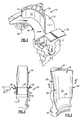
- FIG. 1 An example turbine blade rotor assembly 10 is shown in Figure 1 .
- the assembly 10 includes a rotor 12 that supports a blade 14 by its root 18.
- the blade 14 extends from the root 18 to a tip 21 ( Figure 2 ) to provide an airfoil 20.
- the blade 14 may also include cooling passages 16.
- the blade 14 is constructed from a nickel alloy.
- the airfoil 20 includes pressure and suction sides 22, 24 that extend between leading and trailing edges 26, 28.
- the airfoil 20 includes a perimeter 30 about which one or more platforms 34 are arranged to direct airflow in a desired path.
- the platforms 34 are constructed from a ceramic material, such as a ceramic matrix composite (CMC) or a monolithic ceramic.
- the platforms 34 include a base 36 that is secured to the rotor 12.
- the rotor 12 includes an aperture 38 having a complementary shape to that of the base 36.
- the platforms 34 shown in Figure 1 are arranged adjacent to the pressure and suction sides 22, 24, extending approximately to the leading and trailing edges 26, 28.
- Flow guides 40 are arranged on either side of the airfoil 20 at the leading and trailing edges 26, 28.
- the flow guides 40 can also be constructed from a CMC.
- the blade 14 includes a root 18 having a fir-tree shape that is received in a complementary slot 32 ( Figure 1 ).
- the flow guides 40 include structure that is also received in the slot 32. Referring to Figures 2 and 3 , the flow guides 40 are secured about the platforms 34 and blades 14 to the rotor 12 by a retainer 42. The flow guides 40 are arranged axially adjacent to structure 44.
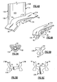
- a platform 134 includes a base 136 having apertures 50 that align with a hole 48 in the rotor structure 46, which is illustrated in a highly schematic fashion.
- a pin 52 is received by the hole 48 and the apertures 50 to secure the platform 134 to the rotor structure 46.
- a platform 234 includes flow guides 56 integrated to the platform 234.
- the platform 234 includes opposing sides 54 that are adjacent to the airfoil 120 about perimeter 130.
- the integrated flow guides 56 extend beyond the leading and trailing edges 126, 128.
- One of the sides 54 is arranged adjacent to the high pressure side 122, and the other side 54 is arranged adjacent to the low pressure side of another blade 114 (not shown).
- FIG. 5A-5D A cross-section of various platforms are shown in Figures 5A-5D .
- the base 136 includes fibers 58 that are oriented to wrap about the aperture 50 to increase the strength of the base 136.
- a platform 236 includes a cavity 60 filled with a material 62 that is different than the ceramic matrix composite material of the platform 236. The material 62 further lightens the platform 236 to reduce the stress on the platform 236.
- a platform 336 includes fillets 66 extending from an outer surface 64. The fillets 66 are provided on the opposing sides 154 adjacent to the surface of the blade 14.
- the blades 210 include protrusions 70 extending from the airfoil to support a platform 436.
- the protrusions 70 supported the platform 436 in a radial direction.
- the platform may, in a further embodiment, have recesses on opposing sides for receiving the protrusions 70.
- FIG. 6 and 7 Another example arrangement between the protrusions 70 and platform 536 is shown in Figures 6 and 7 .
- the platforms 536 are secured not by the rotor, but instead by the base of adjacent turbine vanes 214.
- the platform 536 includes opposing sides 254 having longitudinal recesses 80 that receive the protrusions 70.
- the vane 214 includes a root 118 having a footed configuration. The root is supported by a case (not shown).
- a vane 214 includes an airfoil 220 that extends to a tip 121 adjacent to a vane outer air shroud 74.
- a perimeter 230 of the airfoil 220 is received by an opening 78 of an inner flowpath surface 72.
- the inner flowpath surface 72 is constructed from a ceramic matrix composite material.
- the inner flowpath surface 72 extends substantially around the perimeter 230. That is, the inner flowpath surface 72 substantially surrounds the pressure and suction sides 222, 224 and the leading and trailing edges 226, 228.
- the inner flowpath surface serves as a platform 76 that supports an inner seal assembly 112.
- the vane 314 extends through the opening 178.
Landscapes
- Engineering & Computer Science (AREA)
- Mechanical Engineering (AREA)
- General Engineering & Computer Science (AREA)
- Turbine Rotor Nozzle Sealing (AREA)
Abstract
Description
- This disclosure relates to a turbine blade rotor assembly. In particular, the disclosure relates to an assembly for which a platform adjacent to the turbine blade is provided by a separate structure.
- Typical turbine blades for a gas turbine engine are constructed from a nickel alloy. Multiple turbine blades are arranged circumferentially about a rotor and secured thereto by their roots. Typically, turbine blades include integral platforms extending circumferentially from both the high and low pressure sides of the airfoil near the root. The platforms act as flow guides that divert airflow along a desired flow path.
- It is desirable to increase turbine rotor speed to improve the performance and efficiency of gas turbine engines. The turbine rotor speed is limited by the loads on the turbine blades. In particular, the turbine blades, which are typically constructed from nickel alloy, speed can be limited by the attached platforms, which curl and crack under loads.
- In an effort to reduce turbine blade cooling flows, it has been suggested that turbine blades could be constructed from a ceramic matrix composite (CMC). This design approach endeavored to eliminate the use of nickel in the turbine blade and substitute a high temperature CMC. The layered construction of the CMC blade favors a direct connection between the attachment feature and the airfoil itself. To simplify the construction, the platforms are provided by separate structure that is secured to the rotor because providing an integral platform to a CMC blade is very difficult.
- The current state of the art cooling schemes for nickel alloy blade have improved the thermal capability such that alternative material such as CMC may not offer significant benefits. However, the problem of blade platform capability remains. Thus, it is desirable to utilize a nickel alloy blade that does not have platforms that crack at increased turbine rotor speeds.
- In a first aspect of the invention, a turbine blade rotor assembly is disclosed for a gas turbine engine. The assembly includes a rotor having nickel alloy turbine blades secured thereto. Each of the blades includes a root and an airfoil. The roots are supported by the rotor. A ceramic, e.g. a ceramic matrix composite, platform separate from the turbine blades is supported between each pair of the turbine blades adjacent to the airfoils. The blades may include cooling passages within the airfoil.
- In a further aspect of the invention, an airfoil includes a perimeter. A shroud having an aperture receives the airfoil with a single shroud substantially surrounding the airfoil at the perimeter. The perimeter may include pressure and suction sides and leading and trailing edges, with the single shroud extending from the leading and trailing edges along and adjacent to both the high and low pressure sides.
- In a further aspect of the invention, a turbine blade includes high and low pressure sides opposite one another that extend from a tip to a root. The airfoil is free from any protrusions extending from the high and low pressure sides on a portion of the blade axially outward from the root. The blade may have a fir-tree shape. The airfoil may be a nickel alloy.
- These and other features of the disclosure can be best understood from the following specification and drawings, the following of which is a brief description.
-
-
Figure 1 is a perspective view of an example turbine blade rotor assembly. -
Figure 2 is a perspective view of a turbine blade shown inFigure 1 . -
Figure 3 is a side elevational view of the assembly shown inFigure 1 . -
Figure 4A is a perspective view of one example platform. -
Figure 4B is a perspective view of another example platform. -
Figures 5A-5D are cross-sectional views of example platform and base configurations. -
Figure 6 is a cross-sectional view of a pair of turbine vanes and platforms arranged between the turbine blades. -
Figure 7 is a perspective view of an example turbine vane with a ceramic matrix composite shroud. -
Figure 8 is a perspective view of a shroud supported by a platform through which the turbine vanes extend. - An example turbine
blade rotor assembly 10 is shown inFigure 1 . Theassembly 10 includes arotor 12 that supports ablade 14 by itsroot 18. Theblade 14 extends from theroot 18 to a tip 21 (Figure 2 ) to provide anairfoil 20. Theblade 14 may also includecooling passages 16. In one example, theblade 14 is constructed from a nickel alloy. - The
airfoil 20 includes pressure andsuction sides trailing edges airfoil 20 includes aperimeter 30 about which one ormore platforms 34 are arranged to direct airflow in a desired path. Theplatforms 34 are constructed from a ceramic material, such as a ceramic matrix composite (CMC) or a monolithic ceramic. Theplatforms 34 include abase 36 that is secured to therotor 12. In the example shown inFigure 1 , therotor 12 includes anaperture 38 having a complementary shape to that of thebase 36. Theplatforms 34 shown inFigure 1 are arranged adjacent to the pressure andsuction sides trailing edges Flow guides 40 are arranged on either side of theairfoil 20 at the leading andtrailing edges flow guides 40 can also be constructed from a CMC. - In the example shown in
Figure 2 , theblade 14 includes aroot 18 having a fir-tree shape that is received in a complementary slot 32 (Figure 1 ). Theflow guides 40 include structure that is also received in theslot 32. Referring toFigures 2 and 3 , theflow guides 40 are secured about theplatforms 34 andblades 14 to therotor 12 by aretainer 42. Theflow guides 40 are arranged axially adjacent tostructure 44. - Referring to
Figure 4A , aplatform 134 includes abase 136 havingapertures 50 that align with ahole 48 in therotor structure 46, which is illustrated in a highly schematic fashion. A pin 52 is received by thehole 48 and theapertures 50 to secure theplatform 134 to therotor structure 46. In another example shown inFigure 4B , aplatform 234 includesflow guides 56 integrated to theplatform 234. Theplatform 234 includesopposing sides 54 that are adjacent to theairfoil 120 aboutperimeter 130. The integratedflow guides 56 extend beyond the leading andtrailing edges sides 54 is arranged adjacent to thehigh pressure side 122, and theother side 54 is arranged adjacent to the low pressure side of another blade 114 (not shown). - A cross-section of various platforms are shown in
Figures 5A-5D . In the example shown inFigure 5A , thebase 136 includesfibers 58 that are oriented to wrap about theaperture 50 to increase the strength of thebase 136. In another example shown inFigure 5B , aplatform 236 includes acavity 60 filled with a material 62 that is different than the ceramic matrix composite material of theplatform 236. The material 62 further lightens theplatform 236 to reduce the stress on theplatform 236. Referring toFigure 5C , aplatform 336 includesfillets 66 extending from anouter surface 64. Thefillets 66 are provided on the opposing sides 154 adjacent to the surface of theblade 14. Referring toFigure 5D , theblades 210 includeprotrusions 70 extending from the airfoil to support aplatform 436. Theprotrusions 70 supported theplatform 436 in a radial direction. The platform may, in a further embodiment, have recesses on opposing sides for receiving theprotrusions 70. - Another example arrangement between the
protrusions 70 andplatform 536 is shown inFigures 6 and 7 . In the example, theplatforms 536 are secured not by the rotor, but instead by the base ofadjacent turbine vanes 214. Theplatform 536 includes opposingsides 254 havinglongitudinal recesses 80 that receive theprotrusions 70. Thevane 214 includes aroot 118 having a footed configuration. The root is supported by a case (not shown). - Referring to
Figure 7 , avane 214 includes anairfoil 220 that extends to atip 121 adjacent to a vaneouter air shroud 74. A perimeter 230 of theairfoil 220 is received by an opening 78 of aninner flowpath surface 72. Theinner flowpath surface 72 is constructed from a ceramic matrix composite material. Theinner flowpath surface 72 extends substantially around the perimeter 230. That is, theinner flowpath surface 72 substantially surrounds the pressure andsuction sides edges Figure 8 , the inner flowpath surface serves as aplatform 76 that supports aninner seal assembly 112. Thevane 314 extends through the opening 178. - Although example embodiments have been disclosed, a worker of ordinary skill in this art would recognize that certain modifications would come within the scope of the claims. For that reason, the following claims should be studied to determine their true scope and content.
Claims (15)
- A turbine blade rotor assembly for a gas turbine engine comprising:a rotor (12);nickel alloy turbine blades (14) each having a root (18) and an airfoil (20), the roots (18) supported by the rotor (12); anda ceramic platform (34) supported between each pair of the turbine blades (14) adjacent to the airfoils (20).
- The assembly according to claim 1, wherein the turbine blades (14) include pressure and suction sides (22, 24) opposite from one another and including lateral protrusions extending from the pressure and suction sides (22, 24), the platform (34) including opposing sides supported by the protrusions.
- The assembly according to claim 2, wherein each of the opposing sides includes a longitudinal recess (80) that receives the protrusion (70) of an adjacent turbine blade.
- The assembly according to any of claims 1 to 3, wherein the platforms (134) include a base (136) having an aperture (50), and the rotor (12) includes a hole (48), a pin (52) received in the hole (48) and the aperture (50) securing each platform (134) to the rotor (12).
- The assembly according to claim 4, wherein the ceramic is a ceramic matrix composite including fibers (58), the fibers (58) in the base wrapped around the aperture (50) in a desired orientation.
- The assembly according to any preceding claim, wherein the turbine blades (14) include leading and trailing edges (26, 28) opposite one another, and comprising leading and trailing flow guides (40) supported by the rotor (12) and arranged axially from the leading and trailing edges (26, 28) respectively, the flow guides (40) are discrete from the platforms (34).
- The assembly according to claim 6, comprising at least one retainer (42) secured relative to the rotor (12) adjacent to the flow guides (40) for maintaining a desired position of the flow guides (40).
- The assembly according to claim 6 or 7, wherein the flow guides (40) include a ceramic material.
- The assembly according to any preceding claim, wherein the platforms (236) include a base secured to the rotor, the base including a cavity (60) filled with a material that is different than the ceramic of the platforms (236).
- The assembly according to any preceding claim, wherein the platforms (336) include an outer surface (64) opposite the rotor (12), the outer surface (64) include including opposing fillets (66) extending longitudinally next to an adjacent turbine blade (14).
- A turbine vane assembly for a gas turbine engine comprising:a turbine vane (214) include an airfoil (220) extending from a root (118), the airfoil (220) having a perimeter (230); anda shroud (72) having an aperture (78; 178) receiving the airfoil, with a single shroud substantially surrounding the airfoil (220) at the perimeter (230).
- The assembly according to claim 11, wherein the shroud is an inner flowpath surface near a vane inner air seal.
- The assembly according to claim 11 or 12, comprising a case supporting the root, wherein the shroud is a platform near the root, the platform secured to the vane.
- The assembly according to claim 13, wherein the root includes legs axially spaced from one another, each leg including spaced apart feet supported on the case.
- A turbine blade (14) for a gas turbine engine comprising:an airfoil (20) including pressure and suction sides (22, 24) opposite one another that extend from a tip to a root (18) without any protrusions extending from the pressure and suction sides (22, 24) on a portion of the blade (14) axially outwardly from the root (18).
Priority Applications (1)
| Application Number | Priority Date | Filing Date | Title |
|---|---|---|---|
| EP14161778.7A EP2752557B1 (en) | 2008-04-11 | 2009-03-25 | Platformless turbine blade |
Applications Claiming Priority (1)
| Application Number | Priority Date | Filing Date | Title |
|---|---|---|---|
| US12/101,326 US8408874B2 (en) | 2008-04-11 | 2008-04-11 | Platformless turbine blade |
Related Child Applications (2)
| Application Number | Title | Priority Date | Filing Date |
|---|---|---|---|
| EP14161778.7A Division EP2752557B1 (en) | 2008-04-11 | 2009-03-25 | Platformless turbine blade |
| EP14161778.7A Division-Into EP2752557B1 (en) | 2008-04-11 | 2009-03-25 | Platformless turbine blade |
Publications (3)
| Publication Number | Publication Date |
|---|---|
| EP2108785A2 true EP2108785A2 (en) | 2009-10-14 |
| EP2108785A3 EP2108785A3 (en) | 2013-01-09 |
| EP2108785B1 EP2108785B1 (en) | 2017-10-04 |
Family
ID=40846162
Family Applications (2)
| Application Number | Title | Priority Date | Filing Date |
|---|---|---|---|
| EP09250851.4A Active EP2108785B1 (en) | 2008-04-11 | 2009-03-25 | Turbine blade and vane assembly with a ceramic platform |
| EP14161778.7A Active EP2752557B1 (en) | 2008-04-11 | 2009-03-25 | Platformless turbine blade |
Family Applications After (1)
| Application Number | Title | Priority Date | Filing Date |
|---|---|---|---|
| EP14161778.7A Active EP2752557B1 (en) | 2008-04-11 | 2009-03-25 | Platformless turbine blade |
Country Status (2)
| Country | Link |
|---|---|
| US (1) | US8408874B2 (en) |
| EP (2) | EP2108785B1 (en) |
Cited By (14)
| Publication number | Priority date | Publication date | Assignee | Title |
|---|---|---|---|---|
| FR2962156A1 (en) * | 2010-07-02 | 2012-01-06 | Snecma | Mobile wheel for low pressure turbine of gas turbine engine in aeronautical field, has screw for fixing foot of each of blades on one of teeth of metal disk, and locking plate interposed between head of screw and foot of each blade |
| FR2963383A1 (en) * | 2010-07-27 | 2012-02-03 | Snecma | DUST OF TURBOMACHINE, ROTOR, LOW PRESSURE TURBINE AND TURBOMACHINE EQUIPPED WITH SUCH A DAWN |
| WO2013144035A1 (en) | 2012-03-28 | 2013-10-03 | Alstom Technology Ltd | Method for processing a modular hybrid component |
| WO2013144024A1 (en) | 2012-03-28 | 2013-10-03 | Alstom Technology Ltd | Method for separating a metal part from a ceramic part |
| WO2014039974A1 (en) * | 2012-09-10 | 2014-03-13 | General Electric Company | Low radius ratio fan for a gas turbine engine |
| FR3032753A1 (en) * | 2015-02-16 | 2016-08-19 | Snecma | RECTIFIER FOR A TURBOMACHINE |
| EP3170983A1 (en) * | 2015-11-23 | 2017-05-24 | United Technologies Corporation | Platform and corresponding method of manufacturing |
| EP2570600A3 (en) * | 2011-09-08 | 2017-11-15 | General Electric Company | Turbine rotor blade assembly and method of assembling same |
| US10227880B2 (en) | 2015-11-10 | 2019-03-12 | General Electric Company | Turbine blade attachment mechanism |
| US10677075B2 (en) | 2018-05-04 | 2020-06-09 | General Electric Company | Composite airfoil assembly for an interdigitated rotor |
| EP3751103A1 (en) * | 2019-06-14 | 2020-12-16 | Raytheon Technologies Corporation | Ceramic matrix composite rotor blade attachment |
| US10941665B2 (en) | 2018-05-04 | 2021-03-09 | General Electric Company | Composite airfoil assembly for an interdigitated rotor |
| US11156110B1 (en) | 2020-08-04 | 2021-10-26 | General Electric Company | Rotor assembly for a turbine section of a gas turbine engine |
| US11655719B2 (en) | 2021-04-16 | 2023-05-23 | General Electric Company | Airfoil assembly |
Families Citing this family (26)
| Publication number | Priority date | Publication date | Assignee | Title |
|---|---|---|---|---|
| US8262345B2 (en) * | 2009-02-06 | 2012-09-11 | General Electric Company | Ceramic matrix composite turbine engine |
| KR101785997B1 (en) * | 2009-10-30 | 2017-10-17 | 주식회사 골드피크이노베이션즈 | Transmitting method for information of component carrir grouping and base station thereof, receiving method of terminal in wireless communication system |
| US20120156045A1 (en) * | 2010-12-17 | 2012-06-21 | General Electric Company | Methods, systems and apparatus relating to root and platform configurations for turbine rotor blades |
| EP2644828A1 (en) * | 2012-03-29 | 2013-10-02 | Siemens Aktiengesellschaft | Modular turbine blade having a platform |
| EP2882941B1 (en) | 2012-06-30 | 2021-09-29 | General Electric Company | A turbine blade sealing structure with a specific arrangement of plies |
| US9527262B2 (en) | 2012-09-28 | 2016-12-27 | General Electric Company | Layered arrangement, hot-gas path component, and process of producing a layered arrangement |
| US20140161616A1 (en) * | 2012-12-12 | 2014-06-12 | United Technologies Corporation | Multi-piece blade for gas turbine engine |
| US9453422B2 (en) | 2013-03-08 | 2016-09-27 | General Electric Company | Device, system and method for preventing leakage in a turbine |
| US9759082B2 (en) | 2013-03-12 | 2017-09-12 | Rolls-Royce Corporation | Turbine blade track assembly |
| US9458726B2 (en) | 2013-03-13 | 2016-10-04 | Rolls-Royce Corporation | Dovetail retention system for blade tracks |
| US10202853B2 (en) | 2013-09-11 | 2019-02-12 | General Electric Company | Ply architecture for integral platform and damper retaining features in CMC turbine blades |
| EP3055509B1 (en) | 2013-10-11 | 2024-03-06 | RTX Corporation | Ceramic matrix composite gas turbine blade with monolithic ceramic platform and dovetail |
| JP6479328B2 (en) * | 2014-04-02 | 2019-03-06 | 三菱日立パワーシステムズ株式会社 | Rotor and rotary machine |
| JP2017530290A (en) * | 2014-08-22 | 2017-10-12 | シーメンス エナジー インコーポレイテッド | Modular turbine blade with separate platform support system |
| US10280768B2 (en) | 2014-11-12 | 2019-05-07 | Rolls-Royce North American Technologies Inc. | Turbine blisk including ceramic matrix composite blades and methods of manufacture |
| US9909430B2 (en) | 2014-11-13 | 2018-03-06 | Rolls-Royce North American Technologies Inc. | Turbine disk assembly including seperable platforms for blade attachment |
| US20160186593A1 (en) * | 2014-12-31 | 2016-06-30 | General Electric Company | Flowpath boundary and rotor assemblies in gas turbines |
| US20160305260A1 (en) * | 2015-03-04 | 2016-10-20 | Rolls-Royce North American Technologies, Inc. | Bladed wheel with separable platform |
| US10294954B2 (en) | 2016-11-09 | 2019-05-21 | Rolls-Royce North American Technologies Inc. | Composite blisk |
| US10358922B2 (en) | 2016-11-10 | 2019-07-23 | Rolls-Royce Corporation | Turbine wheel with circumferentially-installed inter-blade heat shields |
| US10563665B2 (en) | 2017-01-30 | 2020-02-18 | Rolls-Royce North American Technologies, Inc. | Turbomachine stage and method of making same |
| US10731487B2 (en) | 2017-02-20 | 2020-08-04 | General Electric Company | Turbine components and methods of manufacturing |
| US10767498B2 (en) | 2018-04-03 | 2020-09-08 | Rolls-Royce High Temperature Composites Inc. | Turbine disk with pinned platforms |
| US10577961B2 (en) | 2018-04-23 | 2020-03-03 | Rolls-Royce High Temperature Composites Inc. | Turbine disk with blade supported platforms |
| US10890081B2 (en) | 2018-04-23 | 2021-01-12 | Rolls-Royce Corporation | Turbine disk with platforms coupled to disk |
| US11131203B2 (en) | 2018-09-26 | 2021-09-28 | Rolls-Royce Corporation | Turbine wheel assembly with offloaded platforms and ceramic matrix composite blades |
Citations (2)
| Publication number | Priority date | Publication date | Assignee | Title |
|---|---|---|---|---|
| WO2000057032A1 (en) | 1999-03-24 | 2000-09-28 | Siemens Aktiengesellschaft | Guide blade and guide blade rim for a fluid-flow machine and component for delimiting a flow channel |
| EP1219787A1 (en) | 2000-12-27 | 2002-07-03 | Siemens Aktiengesellschaft | Gas turbine blade and gas turbine |
Family Cites Families (20)
| Publication number | Priority date | Publication date | Assignee | Title |
|---|---|---|---|---|
| US3694104A (en) * | 1970-10-07 | 1972-09-26 | Garrett Corp | Turbomachinery blade |
| US4501053A (en) * | 1982-06-14 | 1985-02-26 | United Technologies Corporation | Method of making rotor blade for a rotary machine |
| US5030063A (en) * | 1990-02-08 | 1991-07-09 | General Motors Corporation | Turbomachine rotor |
| US5222865A (en) * | 1991-03-04 | 1993-06-29 | General Electric Company | Platform assembly for attaching rotor blades to a rotor disk |
| US5240377A (en) * | 1992-02-25 | 1993-08-31 | Williams International Corporation | Composite fan blade |
| US5310317A (en) * | 1992-08-11 | 1994-05-10 | General Electric Company | Quadra-tang dovetail blade |
| DE19941134C1 (en) * | 1999-08-30 | 2000-12-28 | Mtu Muenchen Gmbh | Blade crown ring for gas turbine aircraft engine has each blade provided with transition region between blade surface and blade platform having successively decreasing curvature radii |
| US6190131B1 (en) * | 1999-08-31 | 2001-02-20 | General Electric Co. | Non-integral balanced coverplate and coverplate centering slot for a turbine |
| US7284958B2 (en) * | 2003-03-22 | 2007-10-23 | Allison Advanced Development Company | Separable blade platform |
| US7007382B2 (en) | 2003-07-24 | 2006-03-07 | United Technologies Corporation | Slot machining |
| US6951447B2 (en) | 2003-12-17 | 2005-10-04 | United Technologies Corporation | Turbine blade with trailing edge platform undercut |
| US7094021B2 (en) | 2004-02-02 | 2006-08-22 | General Electric Company | Gas turbine flowpath structure |
| US7261518B2 (en) | 2005-03-24 | 2007-08-28 | Siemens Demag Delaval Turbomachinery, Inc. | Locking arrangement for radial entry turbine blades |
| US7255536B2 (en) | 2005-05-23 | 2007-08-14 | United Technologies Corporation | Turbine airfoil platform cooling circuit |
| US7300253B2 (en) | 2005-07-25 | 2007-11-27 | Siemens Aktiengesellschaft | Gas turbine blade or vane and platform element for a gas turbine blade or vane ring of a gas turbine, supporting structure for securing gas turbine blades or vanes arranged in a ring, gas turbine blade or vane ring and the use of a gas turbine blade or vane ring |
| US7467924B2 (en) | 2005-08-16 | 2008-12-23 | United Technologies Corporation | Turbine blade including revised platform |
| US7334995B2 (en) * | 2005-11-22 | 2008-02-26 | Siemens Power Generation, Inc. | Turbine blade assembly and method of manufacture |
| US7510379B2 (en) | 2005-12-22 | 2009-03-31 | General Electric Company | Composite blading member and method for making |
| US7507466B2 (en) | 2006-02-22 | 2009-03-24 | General Electric Company | Manufacture of CMC articles having small complex features |
| US7874804B1 (en) * | 2007-05-10 | 2011-01-25 | Florida Turbine Technologies, Inc. | Turbine blade with detached platform |
-
2008
- 2008-04-11 US US12/101,326 patent/US8408874B2/en active Active
-
2009
- 2009-03-25 EP EP09250851.4A patent/EP2108785B1/en active Active
- 2009-03-25 EP EP14161778.7A patent/EP2752557B1/en active Active
Patent Citations (2)
| Publication number | Priority date | Publication date | Assignee | Title |
|---|---|---|---|---|
| WO2000057032A1 (en) | 1999-03-24 | 2000-09-28 | Siemens Aktiengesellschaft | Guide blade and guide blade rim for a fluid-flow machine and component for delimiting a flow channel |
| EP1219787A1 (en) | 2000-12-27 | 2002-07-03 | Siemens Aktiengesellschaft | Gas turbine blade and gas turbine |
Cited By (22)
| Publication number | Priority date | Publication date | Assignee | Title |
|---|---|---|---|---|
| FR2962156A1 (en) * | 2010-07-02 | 2012-01-06 | Snecma | Mobile wheel for low pressure turbine of gas turbine engine in aeronautical field, has screw for fixing foot of each of blades on one of teeth of metal disk, and locking plate interposed between head of screw and foot of each blade |
| FR2963383A1 (en) * | 2010-07-27 | 2012-02-03 | Snecma | DUST OF TURBOMACHINE, ROTOR, LOW PRESSURE TURBINE AND TURBOMACHINE EQUIPPED WITH SUCH A DAWN |
| US8951017B2 (en) | 2010-07-27 | 2015-02-10 | Snecma | Turbomachine blade, a rotor, a low pressure turbine, and a turbomachine fitted with such a blade |
| US10287897B2 (en) | 2011-09-08 | 2019-05-14 | General Electric Company | Turbine rotor blade assembly and method of assembling same |
| EP2570600A3 (en) * | 2011-09-08 | 2017-11-15 | General Electric Company | Turbine rotor blade assembly and method of assembling same |
| WO2013144035A1 (en) | 2012-03-28 | 2013-10-03 | Alstom Technology Ltd | Method for processing a modular hybrid component |
| WO2013144024A1 (en) | 2012-03-28 | 2013-10-03 | Alstom Technology Ltd | Method for separating a metal part from a ceramic part |
| CN104619955B (en) * | 2012-09-10 | 2016-10-19 | 通用电气公司 | Low radius ratio fan for gas-turbine unit |
| WO2014039974A1 (en) * | 2012-09-10 | 2014-03-13 | General Electric Company | Low radius ratio fan for a gas turbine engine |
| JP2015528540A (en) * | 2012-09-10 | 2015-09-28 | ゼネラル・エレクトリック・カンパニイ | Low radius ratio fan for gas turbine engines |
| US9239062B2 (en) | 2012-09-10 | 2016-01-19 | General Electric Company | Low radius ratio fan for a gas turbine engine |
| CN104619955A (en) * | 2012-09-10 | 2015-05-13 | 通用电气公司 | Low radius ratio fan for a gas turbine engine |
| FR3032753A1 (en) * | 2015-02-16 | 2016-08-19 | Snecma | RECTIFIER FOR A TURBOMACHINE |
| US10227880B2 (en) | 2015-11-10 | 2019-03-12 | General Electric Company | Turbine blade attachment mechanism |
| EP3170983A1 (en) * | 2015-11-23 | 2017-05-24 | United Technologies Corporation | Platform and corresponding method of manufacturing |
| US10584592B2 (en) | 2015-11-23 | 2020-03-10 | United Technologies Corporation | Platform for an airfoil having bowed sidewalls |
| US10677075B2 (en) | 2018-05-04 | 2020-06-09 | General Electric Company | Composite airfoil assembly for an interdigitated rotor |
| US10941665B2 (en) | 2018-05-04 | 2021-03-09 | General Electric Company | Composite airfoil assembly for an interdigitated rotor |
| EP3751103A1 (en) * | 2019-06-14 | 2020-12-16 | Raytheon Technologies Corporation | Ceramic matrix composite rotor blade attachment |
| US11261744B2 (en) | 2019-06-14 | 2022-03-01 | Raytheon Technologies Corporation | Ceramic matrix composite rotor blade attachment |
| US11156110B1 (en) | 2020-08-04 | 2021-10-26 | General Electric Company | Rotor assembly for a turbine section of a gas turbine engine |
| US11655719B2 (en) | 2021-04-16 | 2023-05-23 | General Electric Company | Airfoil assembly |
Also Published As
| Publication number | Publication date |
|---|---|
| US20090257875A1 (en) | 2009-10-15 |
| EP2108785A3 (en) | 2013-01-09 |
| EP2752557A3 (en) | 2014-09-10 |
| EP2752557B1 (en) | 2019-02-06 |
| US8408874B2 (en) | 2013-04-02 |
| EP2108785B1 (en) | 2017-10-04 |
| EP2752557A2 (en) | 2014-07-09 |
Similar Documents
| Publication | Publication Date | Title |
|---|---|---|
| US8408874B2 (en) | Platformless turbine blade | |
| EP2077376B1 (en) | Rotor blade attachment in a gas turbine | |
| US9279331B2 (en) | Gas turbine engine airfoil with dirt purge feature and core for making same | |
| US7410342B2 (en) | Airfoil support | |
| EP2374997B1 (en) | Component for a gas turbine engine | |
| US8444389B1 (en) | Multiple piece turbine rotor blade | |
| EP2703601B1 (en) | Modular Blade or Vane for a Gas Turbine and Gas Turbine with Such a Blade or Vane | |
| US20070041835A1 (en) | Turbine blade including revised trailing edge cooling | |
| US7845907B2 (en) | Blade cooling passage for a turbine engine | |
| GB2353826A (en) | Aerofoil to platform transition in gas turbine blade/vane | |
| CA2313929A1 (en) | Reduced-stress compressor blisk flowpath | |
| JP4245873B2 (en) | Turbine airfoils for gas turbine engines | |
| US10294805B2 (en) | Gas turbine engine integrally bladed rotor with asymmetrical trench fillets | |
| US8221083B2 (en) | Asymmetrical rotor blade fir-tree attachment | |
| EP2625389B1 (en) | Impingement cooling of gas turbine blades or vanes | |
| US8556581B2 (en) | Stator vane assembly | |
| WO2017209752A1 (en) | Asymmetric attachment system for a turbine blade | |
| US8956116B2 (en) | Cooling of a gas turbine component designed as a rotor disk or turbine blade | |
| US9394795B1 (en) | Multiple piece turbine rotor blade | |
| US7413409B2 (en) | Turbine airfoil with weight reduction plenum | |
| KR20060048993A (en) | Turbine blade flared buttress | |
| US10577946B2 (en) | Blade | |
| EP2685047A1 (en) | Modular vane/blade for a gas turbine and gas turbine with such a vane/blade | |
| EP3159482B1 (en) | Blade assembly , corresponding rotor assembly and gas turbine engine | |
| JP2004116364A (en) | Rotor blade in axial-flow turbine |
Legal Events
| Date | Code | Title | Description |
|---|---|---|---|
| PUAI | Public reference made under article 153(3) epc to a published international application that has entered the european phase |
Free format text: ORIGINAL CODE: 0009012 |
|
| AK | Designated contracting states |
Kind code of ref document: A2 Designated state(s): AT BE BG CH CY CZ DE DK EE ES FI FR GB GR HR HU IE IS IT LI LT LU LV MC MK MT NL NO PL PT RO SE SI SK TR |
|
| AX | Request for extension of the european patent |
Extension state: AL BA RS |
|
| PUAL | Search report despatched |
Free format text: ORIGINAL CODE: 0009013 |
|
| AK | Designated contracting states |
Kind code of ref document: A3 Designated state(s): AT BE BG CH CY CZ DE DK EE ES FI FR GB GR HR HU IE IS IT LI LT LU LV MC MK MT NL NO PL PT RO SE SI SK TR |
|
| AX | Request for extension of the european patent |
Extension state: AL BA RS |
|
| RIC1 | Information provided on ipc code assigned before grant |
Ipc: F01D 5/30 20060101ALI20121130BHEP Ipc: F01D 11/00 20060101ALI20121130BHEP Ipc: F01D 9/04 20060101ALI20121130BHEP Ipc: F01D 5/28 20060101AFI20121130BHEP |
|
| 17P | Request for examination filed |
Effective date: 20130708 |
|
| RBV | Designated contracting states (corrected) |
Designated state(s): AT BE BG CH CY CZ DE DK EE ES FI FR GB GR HR HU IE IS IT LI LT LU LV MC MK MT NL NO PL PT RO SE SI SK TR |
|
| AKX | Designation fees paid |
Designated state(s): DE GB |
|
| RAP1 | Party data changed (applicant data changed or rights of an application transferred) |
Owner name: UNITED TECHNOLOGIES CORPORATION |
|
| GRAP | Despatch of communication of intention to grant a patent |
Free format text: ORIGINAL CODE: EPIDOSNIGR1 |
|
| INTG | Intention to grant announced |
Effective date: 20170425 |
|
| GRAA | (expected) grant |
Free format text: ORIGINAL CODE: 0009210 |
|
| GRAS | Grant fee paid |
Free format text: ORIGINAL CODE: EPIDOSNIGR3 |
|
| AK | Designated contracting states |
Kind code of ref document: B1 Designated state(s): DE GB |
|
| REG | Reference to a national code |
Ref country code: GB Ref legal event code: FG4D |
|
| REG | Reference to a national code |
Ref country code: DE Ref legal event code: R096 Ref document number: 602009048660 Country of ref document: DE |
|
| REG | Reference to a national code |
Ref country code: DE Ref legal event code: R097 Ref document number: 602009048660 Country of ref document: DE |
|
| PLBE | No opposition filed within time limit |
Free format text: ORIGINAL CODE: 0009261 |
|
| STAA | Information on the status of an ep patent application or granted ep patent |
Free format text: STATUS: NO OPPOSITION FILED WITHIN TIME LIMIT |
|
| 26N | No opposition filed |
Effective date: 20180705 |
|
| REG | Reference to a national code |
Ref country code: DE Ref legal event code: R081 Ref document number: 602009048660 Country of ref document: DE Owner name: RAYTHEON TECHNOLOGIES CORPORATION (N.D.GES.D.S, US Free format text: FORMER OWNER: UNITED TECHNOLOGIES CORPORATION, FARMINGTON, CONN., US |
|
| PGFP | Annual fee paid to national office [announced via postgrant information from national office to epo] |
Ref country code: GB Payment date: 20230222 Year of fee payment: 15 Ref country code: DE Payment date: 20230221 Year of fee payment: 15 |
|
| P01 | Opt-out of the competence of the unified patent court (upc) registered |
Effective date: 20230519 |