EP2108754A1 - Fastening clamps for fastening frames to brick walls, specific frame and form of assembly - Google Patents
Fastening clamps for fastening frames to brick walls, specific frame and form of assembly Download PDFInfo
- Publication number
- EP2108754A1 EP2108754A1 EP08380106A EP08380106A EP2108754A1 EP 2108754 A1 EP2108754 A1 EP 2108754A1 EP 08380106 A EP08380106 A EP 08380106A EP 08380106 A EP08380106 A EP 08380106A EP 2108754 A1 EP2108754 A1 EP 2108754A1
- Authority
- EP
- European Patent Office
- Prior art keywords
- clamp
- fastening
- specific frame
- clamps
- frame
- Prior art date
- Legal status (The legal status is an assumption and is not a legal conclusion. Google has not performed a legal analysis and makes no representation as to the accuracy of the status listed.)
- Withdrawn
Links
- 239000011449 brick Substances 0.000 title claims abstract description 49
- 238000009877 rendering Methods 0.000 claims abstract description 5
- 239000000853 adhesive Substances 0.000 claims abstract description 4
- 230000001070 adhesive effect Effects 0.000 claims abstract description 4
- 239000004570 mortar (masonry) Substances 0.000 claims description 9
- 239000002023 wood Substances 0.000 claims description 6
- 239000000463 material Substances 0.000 claims description 4
- 238000009434 installation Methods 0.000 claims description 3
- 241000935974 Paralichthys dentatus Species 0.000 claims description 2
- 230000035515 penetration Effects 0.000 claims 2
- 239000011800 void material Substances 0.000 claims 2
- 238000005192 partition Methods 0.000 description 9
- 238000004873 anchoring Methods 0.000 description 3
- 239000002184 metal Substances 0.000 description 2
- 239000007779 soft material Substances 0.000 description 2
- 230000006978 adaptation Effects 0.000 description 1
- 238000010276 construction Methods 0.000 description 1
- 230000008878 coupling Effects 0.000 description 1
- 238000010168 coupling process Methods 0.000 description 1
- 238000005859 coupling reaction Methods 0.000 description 1
- 238000007373 indentation Methods 0.000 description 1
- 235000000396 iron Nutrition 0.000 description 1
- 230000004048 modification Effects 0.000 description 1
- 238000012986 modification Methods 0.000 description 1
- 239000011505 plaster Substances 0.000 description 1
- 239000004033 plastic Substances 0.000 description 1
- 229920003023 plastic Polymers 0.000 description 1
- 238000000638 solvent extraction Methods 0.000 description 1
Images


Classifications
-
- E—FIXED CONSTRUCTIONS
- E04—BUILDING
- E04B—GENERAL BUILDING CONSTRUCTIONS; WALLS, e.g. PARTITIONS; ROOFS; FLOORS; CEILINGS; INSULATION OR OTHER PROTECTION OF BUILDINGS
- E04B1/00—Constructions in general; Structures which are not restricted either to walls, e.g. partitions, or floors or ceilings or roofs
- E04B1/38—Connections for building structures in general
- E04B1/41—Connecting devices specially adapted for embedding in concrete or masonry
- E04B1/4178—Masonry wall ties
- E04B1/4185—Masonry wall ties for cavity walls with both wall leaves made of masonry
Definitions
- the invention relates to a fastening clamp for fastening frames or casings to brick walls to obtain the perfect attachment of the frame to the bricks without damaging the frame or breaking the brick, directly installing same as the partition is being raised.
- the specific frame object of the invention has dovetail-shaped grooving and does not need to be made of a soft material such as wood, since the grooving allows the assembly of the fastening clamp of the invention either by clipping or embedding, being able to freely regulate the height at the time of installation so as to be located between two courses of bricks.
- Conventional wooden frames are used in a second version and the assembly element of the clamp of the invention is nailed by pressure without any impact, without needing added fixing elements such as screws, brads or adhesives. They are installed in the moment of construction, when the partition is raised, in each course of bricks of such that the clamp of the invention is located in or between the joint or heading joint between two rows of bricks.
- the clamp is installed on the installed and plumbed frame, without needing to exert any forces thereon that may shift it, damage the setting of the bricks of the lower courses or weaken the already formed unions.
- partitions and frames are currently done by means of nails, anchor bars, fastening irons or anchors for partitioning.
- the members are previously installed in the frame so that they do not coincide with the joints or heading joints, therefore having to break the bricks. Breaking bricks creates rubble, causes such bricks to lose both acoustic and mechanical strength, as well as making it difficult to perform plasterwork since the parts received with plaster or mortar create an area with high moisture content.
- the advantageous purpose of the invention as can be summarized from the explanation relating to the object thereof in the first paragraphs of this specification is that which provides an essential element of fastening frames to brick walls, with considerable advantages for the builder, the installer and applicr of wall covering because it is a member with important mechanical and functional features, it is self-sufficient and does not require other fixing devices such as brads or screws, which is installed as the partition is being raised, being perfectly placed in the joint without needing to break the brick and having additional anchoring means to improve the attachment to the partition.
- the invention is essentially based on a set of clamps, preferably metal clamps, designed both for being assembled in a specific frame and for being fixed in a common frame, the latter being able to be made of a soft material and the former of any type of material, including hard material
- the clamp is simply and easily assembled without the need of mechanical aid either by guiding it in the specific frame, having a suitable section, or by adapting it laterally by means of a slight coupling movement
- the second case requires a tightening tool for its assembly provided by the invention, or by means of another common tool, such as a grip or vise.
- the clamps according to the invention have the mentioned adaptation configurations and means as well as the features for being placed and located correctly on the plane or edges of the bricks as the wall, partition or the like is raised, such that the part joined to the bricks is firmly held by the mortar joint or heading joint serving as a union to the brick bond. Therefore when the operator finishes the course in which the clamp is to be installed, he or she locates it, applies the mortar mass and places the brick of the following course such that in the first case, the brick is housed in the specific frame in the space set aside for such purpose, and in the second case the brick is housed against the common frame.
- the clamp (1) ( Figure 1 ) is clipped or embedded in the frame (16) by means of side flanges (9) rendering its vertical plane (4) parallel to the vertical wall of the frame.
- Two legs (7) of said clamp (1) and the notch (8) between both legs (7) leave a space for the tongue and groove rib of the brick, the planes (5) of the legs (7) of the clamp (1) being coplanar with the upper edge of the brick.
- the legs (7) have attachment flanges (3) alternately raised in both directions, a hole (6) in font of or behind each flange (3) and also a notch (10) at the outer part.
- the vertical support plane (4) has in its upper central part tangential indentations or corrugations (11) and in its center perpendicular ribs (12) to make the clamp (1) stronger.
- the corners formed by the side flanges (9) and the support plane (11) have perforations (13).
- the clamp (2) is nailed into the frame by means of prongs (14a) and (14b), rendering its plane (4) parallel to the vertical wall of the common frame.
- the two outer prongs (14a) have a retaining point or fluke (15).
- the two legs (7) and the notch (8) leave a space for the tongue and groove rib of the brick, the planes (5) of the clamp (2) being coplanar with the upper edge of the brick.
- the legs (7) have attachment flanges (3) alternately raised in both directions and a hole (6) in front of or behind each flange (3).
- the preferred assembly of the fastening clamp (1) ( Figure 3 ) is carried out with the specific frame (16) provided with a dovetail-shaped inner groove (17).
- the clamp (1) is clipped or embedded by inserting the flanges (9) in the groove (17), which flanges place the plane (4) of the clamp (1) against the plane (20) of the groove, being located above the brick (18), which is also inserted in the groove (17).
- the tongue and groove rib (19) of the brick (18) is housed between the two legs (7) and the notch (8) of the clamp (1).
- the section of Figure 4 is located in the central axis of the leg (7) of the view shown in Figure 3 with the application of the joint (21).
- the legs (7) of the clamp (1) are completely covered by the mortar joint or heading joint (21) for joining the bricks, the holes (6) being filled.
- FIG. 5A The mode of installing the fastening clamp (2) by nailing, Figures 5A , 5B and 5C , for a traditional wood frame (22) is with the aid of tool (23).
- the tool (23) is formed by an actuation lever (24), an eccentric wheel (27) supported on the frame (22) by the part opposite that for the assembly of the clamp (2) and the gripping device (25) with its end (26) equipped with magnets to seek the automatic prc-placement of the clamp (2) therewith.
- the clamp (2) is arranged on the magnets (26) of the gripping device (25), and the assembly is placed embracing the frame (22), the legs (7) of the clamp (2) being supported on the brick (18) with the teeth (14a) and (14b) aimed towards the frame (22).
- the lever (24) is actuated to nail the teeth (14a) and (14b) into the frame (22) until reaching the position described in Figure 5B .
- Figure 5C shows the final placement of the clamp (2) nailed into the frame (22).
Abstract
Description
- As indicated by the title, the invention relates to a fastening clamp for fastening frames or casings to brick walls to obtain the perfect attachment of the frame to the bricks without damaging the frame or breaking the brick, directly installing same as the partition is being raised.
- In a first version, the specific frame object of the invention has dovetail-shaped grooving and does not need to be made of a soft material such as wood, since the grooving allows the assembly of the fastening clamp of the invention either by clipping or embedding, being able to freely regulate the height at the time of installation so as to be located between two courses of bricks.
- Conventional wooden frames are used in a second version and the assembly element of the clamp of the invention is nailed by pressure without any impact, without needing added fixing elements such as screws, brads or adhesives. They are installed in the moment of construction, when the partition is raised, in each course of bricks of such that the clamp of the invention is located in or between the joint or heading joint between two rows of bricks.
- In both cases, the clamp is installed on the installed and plumbed frame, without needing to exert any forces thereon that may shift it, damage the setting of the bricks of the lower courses or weaken the already formed unions.
- The union between partitions and frames is currently done by means of nails, anchor bars, fastening irons or anchors for partitioning. In the case of nailing with brads and of the anchor bars fixed to the frame also with brads, the members are previously installed in the frame so that they do not coincide with the joints or heading joints, therefore having to break the bricks. Breaking bricks creates rubble, causes such bricks to lose both acoustic and mechanical strength, as well as making it difficult to perform plasterwork since the parts received with plaster or mortar create an area with high moisture content. The latest anchoring device for partitions described in Utility Model
ES 1 063 237 U - The advantageous purpose of the invention as can be summarized from the explanation relating to the object thereof in the first paragraphs of this specification is that which provides an essential element of fastening frames to brick walls, with considerable advantages for the builder, the installer and applicr of wall covering because it is a member with important mechanical and functional features, it is self-sufficient and does not require other fixing devices such as brads or screws, which is installed as the partition is being raised, being perfectly placed in the joint without needing to break the brick and having additional anchoring means to improve the attachment to the partition.
- Accordingly, the invention is essentially based on a set of clamps, preferably metal clamps, designed both for being assembled in a specific frame and for being fixed in a common frame, the latter being able to be made of a soft material and the former of any type of material, including hard material In the first case, the clamp is simply and easily assembled without the need of mechanical aid either by guiding it in the specific frame, having a suitable section, or by adapting it laterally by means of a slight coupling movement, whereas the second case requires a tightening tool for its assembly provided by the invention, or by means of another common tool, such as a grip or vise.
- The clamps according to the invention have the mentioned adaptation configurations and means as well as the features for being placed and located correctly on the plane or edges of the bricks as the wall, partition or the like is raised, such that the part joined to the bricks is firmly held by the mortar joint or heading joint serving as a union to the brick bond. Therefore when the operator finishes the course in which the clamp is to be installed, he or she locates it, applies the mortar mass and places the brick of the following course such that in the first case, the brick is housed in the specific frame in the space set aside for such purpose, and in the second case the brick is housed against the common frame.
We will now carry out a broader idea of the features of the invention by referring to the sheets of the drawings accompanying this specification where the preferred details of the invention are shown in a schematic manner and only as an example. -
-
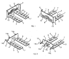
Figure 1 is a front and another rear perspective view of a model of the fastening clamp of the invention (1) for a frame with dovetail-type grooving or the like. -
Figure 2 is a front and another rear perspective view of a model of the fastening clamp (2) for a traditional wood frame. -
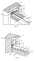
Figure 3 is a perspective view of a preferred assembly of the fastening clamp (1) with the specific frame (16). -
Figure 4 is a section on the central axis of the leg (7) of the view inFigure 3 with the application of the joint (21). -
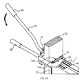
Figures 5A ,5B and5C depict the mode of installing the fastening clamp (2) for a traditional wood frame (22). - The description of the preferred embodiment is centered on the corresponding illustration of the figures of the invention, as follows:
- The clamp (1) (
Figure 1 ) is clipped or embedded in the frame (16) by means of side flanges (9) rendering its vertical plane (4) parallel to the vertical wall of the frame. Two legs (7) of said clamp (1) and the notch (8) between both legs (7) leave a space for the tongue and groove rib of the brick, the planes (5) of the legs (7) of the clamp (1) being coplanar with the upper edge of the brick. The legs (7) have attachment flanges (3) alternately raised in both directions, a hole (6) in font of or behind each flange (3) and also a notch (10) at the outer part. The vertical support plane (4) has in its upper central part tangential indentations or corrugations (11) and in its center perpendicular ribs (12) to make the clamp (1) stronger. The corners formed by the side flanges (9) and the support plane (11) have perforations (13). - In the model of the fastening clamp (2) (
Figure 2 ) for a traditional wood frame, the clamp (2) is nailed into the frame by means of prongs (14a) and (14b), rendering its plane (4) parallel to the vertical wall of the common frame. The two outer prongs (14a) have a retaining point or fluke (15). The two legs (7) and the notch (8) leave a space for the tongue and groove rib of the brick, the planes (5) of the clamp (2) being coplanar with the upper edge of the brick. The legs (7) have attachment flanges (3) alternately raised in both directions and a hole (6) in front of or behind each flange (3). - The preferred assembly of the fastening clamp (1) (
Figure 3 ) is carried out with the specific frame (16) provided with a dovetail-shaped inner groove (17). The clamp (1) is clipped or embedded by inserting the flanges (9) in the groove (17), which flanges place the plane (4) of the clamp (1) against the plane (20) of the groove, being located above the brick (18), which is also inserted in the groove (17). The tongue and groove rib (19) of the brick (18) is housed between the two legs (7) and the notch (8) of the clamp (1). - The section of
Figure 4 is located in the central axis of the leg (7) of the view shown inFigure 3 with the application of the joint (21). The legs (7) of the clamp (1) are completely covered by the mortar joint or heading joint (21) for joining the bricks, the holes (6) being filled. - The mode of installing the fastening clamp (2) by nailing,
Figures 5A ,5B and5C , for a traditional wood frame (22) is with the aid of tool (23). The tool (23) is formed by an actuation lever (24), an eccentric wheel (27) supported on the frame (22) by the part opposite that for the assembly of the clamp (2) and the gripping device (25) with its end (26) equipped with magnets to seek the automatic prc-placement of the clamp (2) therewith. First, as can be seen inFigure 5A , the clamp (2) is arranged on the magnets (26) of the gripping device (25), and the assembly is placed embracing the frame (22), the legs (7) of the clamp (2) being supported on the brick (18) with the teeth (14a) and (14b) aimed towards the frame (22). The lever (24) is actuated to nail the teeth (14a) and (14b) into the frame (22) until reaching the position described inFigure 5B .Figure 5C shows the final placement of the clamp (2) nailed into the frame (22). - Having suitably described the nature of the invention, it is stated for the suitable purposes that the invention is not limited to the express details of this description, but rather that those modifications which do not alter the essential features of the invention could be introduced thereto, in which, all its parts and pieces, except for the fixing elements and pin for releasing the previous anchoring, are manufactured of resistant and aseptic plastics materials, and in which the metering receptacles can be replaced, restored or refilled with absolute ease.
Claims (11)
- Fastening clamps for fastening frames to brick walls, specific frame and form of assembly consisting of a set of clamps that are characterized in that the clamp (1) is installed by clipping or embedding and another clamp (2) is assembled by nailing; the first case is carried out by means of side flanges (9) in a specific frame (16) provided with a dovetail-shaped groove (17) without the need for screws, brads or adhesives, rendering the vertical plane (4) of the clamp (1) parallel to the vertical wall (20) of the specific frame (16), which grooving allowing movements in its groove (17) in the longitudinal direction and being firmly fixed in the transverse direction, and the second case is carried out in a common frame (22) by means of prongs (14a) and (14b) with the aid of an assembly tool (23).
- Fastening clamps for fastening frames to brick walls, specific frame and form of assembly according to claim 1, wherein the clamp (1) applied in a specific frame (16) is characterized by having a central void between the legs (7) and a notch (8) in the vertical plane (4) to allow the tongue and groove connection of the bricks (18) and to render the planes (5) of the clamp (1) coplanar with the upper edge of the brick (18).
- Fastening clamps for fastening frames to brick walls, specific frame and form of assembly according to claims 1 and 2, wherein the legs (7) of the clamp (1) are characterized by having attachment flanges (3) alternately raised in both directions and holes (6) in front of or behind each of them for the penetration of the joint mortar and assuring the correct fastening of the clamp (1) in the union of the bricks, as well as a notch (10) in both outer sides to leave the legs in the width of the brick (18).
- Fastening clamps for fastening frames to brick walls, specific frame and form of assembly according to claims 1 to 3, wherein the vertical support plane (4) of the clamp (1) for the specific frame (16) is characterized in that it has in its upper central part several tangential corrugations (11) and in its center perpendicular ribs (12) to make the clamp (1) stronger and the corners formed by the flanges (9) and the vertical support plane (4) have perforations (13) in their vertexes to favor the clipping action as well as to allow the material or mortar of the joint (21) to penetrate therein.
- Fastening clamps for fastening frames to brick walls, specific frame and form of assembly according to claim 1, wherein the clamp (2) for conventional wood frames (22) is characterized in that it is installed by nailing it into the frame (22) by means of inner prongs (14b) and outer prongs (14a) provided with a retaining point or fluke (15), rendering its vertical plane (4) parallel with the vertical wall of the frame (22) without the need for screws, brads or adhesives.
- Fastening clamps for fastening frames to brick walls, specific frames and form of assembly according to claims 1 and 5, wherein the clamps (1) and (2) are characterized by having a central void between the legs (7) and a notch (8) in the vertical plane (4) to allow the tongue and groove connection of the bricks (18) and to render the planes (5) of the clamp (2) coplanar with the upper edge of the brick (18).
- Fastening clamps for fastening frames to brick walls, specific frame and form of assembly according to claims 1 to 6, wherein the legs (7) and the clamps (1) and (2) are characterized by having attachment flanges (3) alternately raised in both directions and holes (6) in front of or behind each of them for the penetration of the joint mortar or mass therein and assuring the correct fastening of the clamp (2) in the union of the bricks (18).
- Fastening clamps for fastening frames to brick walls, specific frame and form of assembly according to claims 1 and 2, wherein the specific frame (16) is characterized by having a dovetail-shaped inner groove (17) wherein the flanges (9) of the clamp (1) are clipped or embedded, the vertical plane (4) of the clamp (1) being placed against the vertical wall (20) of the groove (17).
- Fastening clamps for fastening frames to brick walls, specific frame and form of assembly according to claims 1, 2 and 8, characterized in that the brick (18) is inserted in the groove (17) of the specific frame (16).
- Fastening clamps for fastening frames to brick walls, specific frame and form of assembly according to claim 1, wherein the installation of the clamp (1) and (2) is characterized by being clipping or nailing as the courses of bricks (18) are added, always coinciding with the mortar joint (21).
- Fastening clamps for fastening frames to brick walls, specific frame and form of assembly according to claim 1, wherein the installation of the clamp (2) is characterized by being nailing of the prongs (14a) and (14b) by pressure without striking which may damage or move the plumbed frame (22), by means of tool (23) which is formed by a lever (24), an eccentric wheel (27) supported on the frame (22) by the part opposite that of the assembly of the clamp (2), a grip (28) and the gripping device (25) with its end (26) equipped with magnets to facilitate the positioning of the clamp (2).
Priority Applications (1)
| Application Number | Priority Date | Filing Date | Title |
|---|---|---|---|
| EP08380106A EP2108754A1 (en) | 2008-04-02 | 2008-04-02 | Fastening clamps for fastening frames to brick walls, specific frame and form of assembly |
Applications Claiming Priority (1)
| Application Number | Priority Date | Filing Date | Title |
|---|---|---|---|
| EP08380106A EP2108754A1 (en) | 2008-04-02 | 2008-04-02 | Fastening clamps for fastening frames to brick walls, specific frame and form of assembly |
Publications (1)
| Publication Number | Publication Date |
|---|---|
| EP2108754A1 true EP2108754A1 (en) | 2009-10-14 |
Family
ID=39720348
Family Applications (1)
| Application Number | Title | Priority Date | Filing Date |
|---|---|---|---|
| EP08380106A Withdrawn EP2108754A1 (en) | 2008-04-02 | 2008-04-02 | Fastening clamps for fastening frames to brick walls, specific frame and form of assembly |
Country Status (1)
| Country | Link |
|---|---|
| EP (1) | EP2108754A1 (en) |
Cited By (4)
| Publication number | Priority date | Publication date | Assignee | Title |
|---|---|---|---|---|
| ITMI20101109A1 (en) * | 2010-06-18 | 2011-12-19 | Vibrapac Spa | ANCHORAGE SYSTEM OF A WALL OF CONCRETE BLOCKS TO A PILLAR ACTING TO SUPPORT TRANSVERSAL MOVEMENTS |
| US9988809B2 (en) | 2016-10-06 | 2018-06-05 | Technologie 2000 Inc. | Construction block anchoring system |
| US10202755B2 (en) | 2016-10-06 | 2019-02-12 | Technologie 2000 Inc. | Construction block anchoring system |
| US10221559B2 (en) * | 2006-10-30 | 2019-03-05 | Michael Hatzinikolas | Wall tie apparatus and method |
Citations (5)
| Publication number | Priority date | Publication date | Assignee | Title |
|---|---|---|---|---|
| GB1575501A (en) * | 1976-11-05 | 1980-09-24 | Ellidge A | Tie means for brick walls |
| CA1137777A (en) * | 1979-11-02 | 1982-12-21 | Catnic Components Limited | Wall-ties |
| DE19829127A1 (en) * | 1998-06-30 | 2000-01-13 | Profil Vertrieb Gmbh | Fastening element for attaching U-shaped support sections to wooden roof beams |
| US20040216408A1 (en) * | 2003-04-30 | 2004-11-04 | Hohmann & Barnard, Inc. | High-strength surface-mounted anchors and wall anchor systems using the same |
| US20060080934A1 (en) * | 2004-10-01 | 2006-04-20 | Robbins Engineering, Inc. | Hanger bracket |
-
2008
- 2008-04-02 EP EP08380106A patent/EP2108754A1/en not_active Withdrawn
Patent Citations (5)
| Publication number | Priority date | Publication date | Assignee | Title |
|---|---|---|---|---|
| GB1575501A (en) * | 1976-11-05 | 1980-09-24 | Ellidge A | Tie means for brick walls |
| CA1137777A (en) * | 1979-11-02 | 1982-12-21 | Catnic Components Limited | Wall-ties |
| DE19829127A1 (en) * | 1998-06-30 | 2000-01-13 | Profil Vertrieb Gmbh | Fastening element for attaching U-shaped support sections to wooden roof beams |
| US20040216408A1 (en) * | 2003-04-30 | 2004-11-04 | Hohmann & Barnard, Inc. | High-strength surface-mounted anchors and wall anchor systems using the same |
| US20060080934A1 (en) * | 2004-10-01 | 2006-04-20 | Robbins Engineering, Inc. | Hanger bracket |
Cited By (4)
| Publication number | Priority date | Publication date | Assignee | Title |
|---|---|---|---|---|
| US10221559B2 (en) * | 2006-10-30 | 2019-03-05 | Michael Hatzinikolas | Wall tie apparatus and method |
| ITMI20101109A1 (en) * | 2010-06-18 | 2011-12-19 | Vibrapac Spa | ANCHORAGE SYSTEM OF A WALL OF CONCRETE BLOCKS TO A PILLAR ACTING TO SUPPORT TRANSVERSAL MOVEMENTS |
| US9988809B2 (en) | 2016-10-06 | 2018-06-05 | Technologie 2000 Inc. | Construction block anchoring system |
| US10202755B2 (en) | 2016-10-06 | 2019-02-12 | Technologie 2000 Inc. | Construction block anchoring system |
Similar Documents
| Publication | Publication Date | Title |
|---|---|---|
| US8051621B2 (en) | Tie system and method for connecting a cementitious backup wall made in a penetrable form and a veneer wall | |
| US10233630B1 (en) | Bracket assembly having a rotating locking plate | |
| EP2108754A1 (en) | Fastening clamps for fastening frames to brick walls, specific frame and form of assembly | |
| KR101664354B1 (en) | Marble panel fixing device for wall exterior | |
| KR200485666Y1 (en) | Insulation fixture for bricks | |
| KR100883627B1 (en) | A hammer | |
| US1774867A (en) | Wall-board tack or staple | |
| JPH083259B2 (en) | Connecting device for structures such as stone materials | |
| US7762031B2 (en) | Strap hold down with restraint opening | |
| JP4136362B2 (en) | Faint | |
| KR100591248B1 (en) | The wall board fixation implement | |
| KR200321381Y1 (en) | Settlement device for setting up adiabatic member and plaster wall on the wall | |
| EP4151811A1 (en) | Retrofit brick tie | |
| US1951711A (en) | Reenforcing and fastening means for tile | |
| JPH0449311Y2 (en) | ||
| KR200321754Y1 (en) | Settlement device for setting up adiabatic member and plaster wall on the wall | |
| JPH0650592Y2 (en) | Corner material | |
| AU759828B2 (en) | Wall tie | |
| JP2006144453A (en) | Double sliding plate and joint device using the same | |
| JPH1181493A (en) | Connecting method and connecting tool for building square timber | |
| JPH0747529Y2 (en) | Metal fittings for building columns | |
| JPH0130647Y2 (en) | ||
| JP2004068597A (en) | Foundation structure of building | |
| JP4125188B2 (en) | Mounting bracket for ALC thin panel | |
| KR20120067074A (en) | Clip for use of coupled on precast unit plate |
Legal Events
| Date | Code | Title | Description |
|---|---|---|---|
| PUAI | Public reference made under article 153(3) epc to a published international application that has entered the european phase |
Free format text: ORIGINAL CODE: 0009012 |
|
| 17P | Request for examination filed |
Effective date: 20080609 |
|
| AK | Designated contracting states |
Kind code of ref document: A1 Designated state(s): AT BE BG CH CY CZ DE DK EE ES FI FR GB GR HR HU IE IS IT LI LT LU LV MC MT NL NO PL PT RO SE SI SK TR |
|
| AX | Request for extension of the european patent |
Extension state: AL BA MK RS |
|
| AKX | Designation fees paid |
Designated state(s): AT BE BG CH CY CZ DE DK EE ES FI FR GB GR HR HU IE IS IT LI LT LU LV MC MT NL NO PL PT RO SE SI SK TR |
|
| STAA | Information on the status of an ep patent application or granted ep patent |
Free format text: STATUS: THE APPLICATION IS DEEMED TO BE WITHDRAWN |
|
| 18D | Application deemed to be withdrawn |
Effective date: 20100915 |