EP2108618A2 - Wasserstoffgenerator - Google Patents
Wasserstoffgenerator Download PDFInfo
- Publication number
- EP2108618A2 EP2108618A2 EP09156184A EP09156184A EP2108618A2 EP 2108618 A2 EP2108618 A2 EP 2108618A2 EP 09156184 A EP09156184 A EP 09156184A EP 09156184 A EP09156184 A EP 09156184A EP 2108618 A2 EP2108618 A2 EP 2108618A2
- Authority
- EP
- European Patent Office
- Prior art keywords
- hydrogen
- chemical hydride
- water
- hollow cylinders
- container
- Prior art date
- Legal status (The legal status is an assumption and is not a legal conclusion. Google has not performed a legal analysis and makes no representation as to the accuracy of the status listed.)
- Granted
Links
- 239000001257 hydrogen Substances 0.000 title claims abstract description 84
- 229910052739 hydrogen Inorganic materials 0.000 title claims abstract description 84
- UFHFLCQGNIYNRP-UHFFFAOYSA-N Hydrogen Chemical compound [H][H] UFHFLCQGNIYNRP-UHFFFAOYSA-N 0.000 title claims abstract description 81
- XLYOFNOQVPJJNP-UHFFFAOYSA-N water Chemical compound O XLYOFNOQVPJJNP-UHFFFAOYSA-N 0.000 claims abstract description 56
- 239000000446 fuel Substances 0.000 claims abstract description 38
- 150000004678 hydrides Chemical class 0.000 claims abstract description 29
- 239000000126 substance Substances 0.000 claims abstract description 28
- 239000000463 material Substances 0.000 claims description 19
- 239000012528 membrane Substances 0.000 claims description 14
- 229910052751 metal Inorganic materials 0.000 claims description 11
- 239000002184 metal Substances 0.000 claims description 11
- 238000006243 chemical reaction Methods 0.000 claims description 10
- 238000000034 method Methods 0.000 claims description 4
- 238000009792 diffusion process Methods 0.000 claims description 2
- 239000012530 fluid Substances 0.000 claims 1
- 238000013022 venting Methods 0.000 claims 1
- 239000007789 gas Substances 0.000 description 5
- 150000002431 hydrogen Chemical class 0.000 description 4
- 238000002485 combustion reaction Methods 0.000 description 3
- RYGMFSIKBFXOCR-UHFFFAOYSA-N Copper Chemical compound [Cu] RYGMFSIKBFXOCR-UHFFFAOYSA-N 0.000 description 2
- 239000012159 carrier gas Substances 0.000 description 2
- 229910052802 copper Inorganic materials 0.000 description 2
- 239000010949 copper Substances 0.000 description 2
- 238000005520 cutting process Methods 0.000 description 2
- 238000007710 freezing Methods 0.000 description 2
- 230000008014 freezing Effects 0.000 description 2
- 239000007788 liquid Substances 0.000 description 2
- 238000004519 manufacturing process Methods 0.000 description 2
- 229910010084 LiAlH4 Inorganic materials 0.000 description 1
- 229910000831 Steel Inorganic materials 0.000 description 1
- 239000000853 adhesive Substances 0.000 description 1
- 230000001070 adhesive effect Effects 0.000 description 1
- 239000003638 chemical reducing agent Substances 0.000 description 1
- 238000001816 cooling Methods 0.000 description 1
- 230000007423 decrease Effects 0.000 description 1
- 238000010304 firing Methods 0.000 description 1
- 238000004817 gas chromatography Methods 0.000 description 1
- 239000008187 granular material Substances 0.000 description 1
- 229910001385 heavy metal Inorganic materials 0.000 description 1
- 230000009191 jumping Effects 0.000 description 1
- 239000012280 lithium aluminium hydride Substances 0.000 description 1
- 229910052987 metal hydride Inorganic materials 0.000 description 1
- 150000004681 metal hydrides Chemical class 0.000 description 1
- 229920000642 polymer Polymers 0.000 description 1
- 239000011148 porous material Substances 0.000 description 1
- 230000005855 radiation Effects 0.000 description 1
- 230000001105 regulatory effect Effects 0.000 description 1
- 239000012266 salt solution Substances 0.000 description 1
- 150000003839 salts Chemical class 0.000 description 1
- 239000007787 solid Substances 0.000 description 1
- 229910001220 stainless steel Inorganic materials 0.000 description 1
- 239000010935 stainless steel Substances 0.000 description 1
- 239000010959 steel Substances 0.000 description 1
- 238000003466 welding Methods 0.000 description 1
Images


Classifications
-
- C—CHEMISTRY; METALLURGY
- C01—INORGANIC CHEMISTRY
- C01B—NON-METALLIC ELEMENTS; COMPOUNDS THEREOF; METALLOIDS OR COMPOUNDS THEREOF NOT COVERED BY SUBCLASS C01C
- C01B3/00—Hydrogen; Gaseous mixtures containing hydrogen; Separation of hydrogen from mixtures containing it; Purification of hydrogen
- C01B3/02—Production of hydrogen or of gaseous mixtures containing a substantial proportion of hydrogen
- C01B3/06—Production of hydrogen or of gaseous mixtures containing a substantial proportion of hydrogen by reaction of inorganic compounds containing electro-positively bound hydrogen, e.g. water, acids, bases, ammonia, with inorganic reducing agents
- C01B3/065—Production of hydrogen or of gaseous mixtures containing a substantial proportion of hydrogen by reaction of inorganic compounds containing electro-positively bound hydrogen, e.g. water, acids, bases, ammonia, with inorganic reducing agents from a hydride
-
- Y—GENERAL TAGGING OF NEW TECHNOLOGICAL DEVELOPMENTS; GENERAL TAGGING OF CROSS-SECTIONAL TECHNOLOGIES SPANNING OVER SEVERAL SECTIONS OF THE IPC; TECHNICAL SUBJECTS COVERED BY FORMER USPC CROSS-REFERENCE ART COLLECTIONS [XRACs] AND DIGESTS
- Y02—TECHNOLOGIES OR APPLICATIONS FOR MITIGATION OR ADAPTATION AGAINST CLIMATE CHANGE
- Y02E—REDUCTION OF GREENHOUSE GAS [GHG] EMISSIONS, RELATED TO ENERGY GENERATION, TRANSMISSION OR DISTRIBUTION
- Y02E60/00—Enabling technologies; Technologies with a potential or indirect contribution to GHG emissions mitigation
- Y02E60/30—Hydrogen technology
- Y02E60/36—Hydrogen production from non-carbon containing sources, e.g. by water electrolysis
Definitions
- Hydrogen is an important gas for many different applications. Many current sources of hydrogen involve heavy metal canisters, which may not be practical for selected applications.
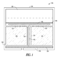
- FIG. 1 is a cross section representation of a hydrogen generator according to an example embodiment.
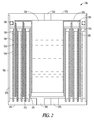
- FIG. 2 is a cross section of a multiple fuel cylinder hydrogen generator according to an example embodiment.
- FIG. 3 is a cross section of a top portion of the hydrogen generator of FIG. 2 .
- FIG. 4 is a cross section of a bottom portion of the hydrogen generator of FIG. 2 .
- a first set of embodiments describes a pressure regulated hydrogen generator using a chemical hydride fuel
- a second set of embodiments describes a hydrogen generator utilizing multiple hollow cylinders of chemical hydride fuel to provide high volume hydrogen production under pressure.
- a hydrogen generator is shown generally in cross section at 100 in FIG. 1 .
- a pressure vessel 110 may be cylindrical in shape, and designed to hold the generator 100 components and generated hydrogen under pressure.
- Vessel 110 may be constructed of steel in one embodiment. Other materials suitable for handling desired pressures and materials may be used in different embodiments.
- a chemical hydride fuel 115 is shown disposed within a portion of the vessel 110.
- the hydride may be disposed within a fuel chamber 120, which may be formed of the same material as the vessel 110.
- the vessel 110 may form portions of the fuel chamber 120 in one embodiment, such as a shared outer wall.
- the fuel chamber 120 in one embodiment has openings 125 that allow water vapor to enter the fuel chamber 120 and interact with the hydride fuel 115 to produce hydrogen.
- An output port 130 is formed through the vessel 110 and chamber 120 to provide hydrogen to an application, such as fuel cell, chemical reactor, balloon, or any other application in need of hydrogen, including hydrogen under pressure.
- the fuel chamber 120 may be formed with a valve seat 135 that provides a seal for a valve disk 140 disposed to regulate access to the openings 125 in chamber 120.
- a valve pin is coupled to valve disk 140 and extends through a shaft 145 extending through the fuel chamber 120 to a flexible diaphragm 150.
- Flexible diaphragm 150 is coupled to the vessel 110 in one embodiment, or otherwise secured, and provided access to ambient, such as via air vents 155.
- the flexible diaphragm/valve pin/valve disk assembly operates as a regulator for the hydrogen generator 100. As pressure builds inside the hydrogen chamber 120, the diaphragm moves down in this example, causing the valve disk 140 to move toward valve seat 135.
- valve disk 140 moves toward valve seat 135, a source of water vapor is cut off from the hydride fuel 115, and production of hydrogen decreases. If more hydrogen is released via output port 130, the valve disk 140 moves away from the valve seat, allowing more water vapor to be provided to the hydride fuel 115, and more hydrogen to be produced.
- water vapor is provided from a water source 155, such as a water and salt solution. Salt may be used to lower the freezing point of the water source 155. Other chemicals and methods of lowering the freezing point of the water source may be used in further embodiments.
- the water source 155 is separated within the vessel 110 from the hydride fuel 115 via a selectively permeable membrane 160, which is water impermeable and water vapor permeable.
- Some potential uses for the hydrogen generator 100 may include: High purity carrier gas for a portable gas chromatograph. Hydrogen source for a proton exchange membrane or solid oxide fuel cell. Portable heat source for cutting, welding, chemical reactions, high temperature sensors. Hydrogen source for a miniature chemical reactor. Hydrogen source as a reducing agent. Constant pressure source for dispensing liquids, microfluidic applications. Pressure source for pneumatic power; pneumatic actuators, valves, pumps. A hydrogen source for rehydriding a metal hydride, applications include fuel cells, sensors, etc. Hydrogen source for generating a hydrogen plasma in a portable device, cutting tool, radiation source (ex. UV). Hydrogen source to generate clean water and power using a fuel cell.
- Pressurized hydrogen source for cooling portable devices As a hydrogen source for a H2/O2 combustion device for firing a projectile. Hydrogen source for a miniature dirigible as a sensing platform for building surveillance. Hydrogen source for a combustion based miniature hot air balloon. Hydrogen source for a toy hydrogen. Generate a calibration gas for a sensor (H2, electrochemical CO, combustible gases, etc). Emergency jumping aide for soldiers using combustion (in a piston, for example) energy from a H2/O2 chemical reaction calculation, a 100 kg soldier can jump 1 meter ⁇ 15 times with 38 grams of LiAlH4, assuming 30% chemical to mechanical conversion efficiency).
- Still further embodiments may provide pressurized hydrogen gas for a wide range of commercial and industrial applications. Some embodiments may be used to replace heavy, metal, gas cylinders of hydrogen. Embodiments may provide a lightweight, more compact hydrogen sources are desired for many portable applications.
- the hydrogen generator 100 may take the form of several different shapes and sizes, in some embodiments, the volume of the generator 100 may be less than 2cc and may be cylindrical in shape. Hydrogen mass flow from such a size may be about 8.2 -6 g/sec with a delivery pressure of about 100 psi.
- the valve assembly may be spring loaded open to obtain desired maximum pressures. This may be accomplished by disposing a spring about the valve pin 145 and supported by the fuel chamber 120 at one end, with the other end biased against the underside of the valve disk 140 to bias the valve disk open.
- the hydrogen generator may operate over various temperatures, such as a range of -40°C to 80°C.
- FIG. 2 is a cross section of an alternative hydrogen producing system 200.
- FIG. 3 illustrates a cross section of a top portion of system 200
- FIG. 4 illustrates a cross section of a bottom portion of system 200.
- the reference numbers are consistent across FIGs. 2 , 3 and 4 .
- System 200 includes multiple hollow cylinders of a hydrogen producing fuel indicated at 205, 210 and 215. Three such cylinders are provided in one embodiment, though further embodiments may contain fewer or more such cylinders arranged in a concentric manner. In various embodiments, the cylinders may be round, or other geometric shapes, such as oval, triangular, rectangular, etc. The term “cylinder” is meant to cover all such geometric shapes, and the term “concentric” is intended to refer to the ability to place different size cylinders within each other.
- the cylinders are formed of a porous chemical hydride formed of granules of chemical hydride sized to provide a large surface area for reaction of the chemical hydride with water vapor.
- the thickness of the cylinders may be selected to result in a bulk reaction of the chemical hydride with the water vapor.
- the water vapor in one embodiment, penetrates through the thickness of the cylinders such that substantially all of the chemical hydride may react with the water vapor.
- a water reservoir 220 is formed inside of the concentric cylinders, and includes a resealable water port 225 to add water to the water reservoir 220 to begin a reaction to produce hydrogen.
- a water wicking material 230 is formed in contact with water in the water reservoir 220. In one embodiment, the wicking material extends down into the water reservoir 220 to transport water form the bottom of the water reservoir 220 as water is consumed to produce hydrogen.
- a second water wicking material 235 which may be formed separately, or as a continuation of the wicking material 230 extends toward the cylinders of fuel, and extends down selected sides of such cylinders, separated by an air gap 240 and a selectively permeable membrane 245.
- the selectively permeable membrane 245 in one embodiment is supported by a metal support 250.
- Metal support 250 in one embodiment is formed of perforated copper to provide for heat transfer and to hold the membrane 245 and fuel in place.
- Cylinder 210 has the wicking material 235 and selectively permeable membrane 245 disposed on both the inside and outside of the cylinder 210 walls. Water vapor from the wicking material 230 and 235 passes through the selectively permeable membrane 245, reacts with the fuel in the cylinders to generate hydrogen, and the hydrogen passes back through the selectively permeable membrane 245. The hydrogen passes through air gaps 240 to an output port 255 formed in a container 260, which provides support for the cylinders and other elements of system 200, as well as suitable containment for generated hydrogen under pressure.
- Container 260 also has concentric slots 265 formed in a base of container 260.
- the slots are formed to provide alignment and support for the metal supports 250 and corresponding membranes 245 to support the cylinders.
- Annular plugs 270 are formed at a top of the fuel cylinders to provide support for the metal supports 250 and form a water tight seal to prevent liquid water from reaching the fuel cylinders.
- the plug 270 for cylinders 210 and 215 have two annular grooves to mate with the metal supports on both sides of the cylinders.
- the plug 270 for cylinder 205 has a single annular groove, with an outside of the plug being smooth for directly contacting container 260.
- an additional metal support 250 may be used on the outside of cylinder 205, in which case the plug 270 for cylinder 205 may have two annular grooves.
- the container 260 contains a base, and walls that may be formed in the same shape as the concentric fuel cylinders disposed within it, and welded or otherwise affixed to the base of container 260.
- a top portion of the walls of container 260 may have threads formed to mate with corresponding threads on a cap 275 that is assembled with the container 260 to form system 200.
- An O-ring 280 may be used to provide a seal between container 260 and cap 275.
- the cap may be welded or otherwise sealed with container 260 to provide sufficient retentive force in the face of hydrogen under pressure.
- Cap 275 in one embodiment includes supports 285 extending toward the base, and forming walls of the water reservoir 220.
- the wicking material 230 and 235 may be supported by the supports 285.
- the supports 285 may be coupled to a top portion of the cap by annular rings 290 formed to space the supports apart to leave room for the fuel cylinders 205, 210 and 215.
- the supports 285 are welded to the rings 290, but may be attached in other manners, such as adhesive or mechanical couplers.
- container 260, cap 275, supports 285 and rings 290 may be formed of 216 stainless steel or other suitable material that provides structural strength to withstand the pressure of generated hydrogen, and also to withstand the chemical reactions occurring in system 200.
- a release valve 295 such as a pressure release valve distributed by Lee Company of Westbrook, CT, may be formed in the container 260 and used to vent excess generated hydrogen when the pressure of hydrogen in container 260 exceeds a predetermined pressure, such as approximately 100 PSI in one embodiment.
- the wicking material 230, 235 may be formed from a wide range of materials that operate to transport water. Pressed fibrous metal, polymers with pores, porous paper and any other water transport film may be used in various embodiments.
- the air gap 240 may be used to diffuse water vapor from the wick, and to provide a path for generated hydrogen to reach the hydrogen output port 255.
- Metal supports 250 may be formed of perforated copper in one embodiment, and may be used to help transfer heat away from the fuel cylinders, as heat is generated in the reaction with water vapor to produce hydrogen. The metal supports 250 also may operate to hold the porous permeable membrane in place, as well as holding the fuel in place within the container 260.
- the concentric cylinders of fuel provide the ability to react the fuel quickly with water vapor and create a high hydrogen generation and flow rate.
- the chemical hydride is porous, with a grain size of from approximately 1 to 100 ⁇ m. In one embodiment, the average grain size is approximately 10 ⁇ m. The size of the grain provides a low diffusion resistance and results in uniform hydrogen generation. A flat discharge rate may be provided with proper grain size and thickness of the cylinders.
- the hydrogen generating system 200 is scalable from a few cc's volume to much larger sizes. In smaller embodiments, the hydrogen generating system 200 may serve to provide a hydrogen carrier gas for portable instruments, such as a gas chromatography instrument. Adding water via water filling port 225, and then resealing the water filling port 225 using a threaded plug, initiates a reaction that starts to produce hydrogen within a short period of time, such as a few minutes or less.
Landscapes
- Chemical & Material Sciences (AREA)
- Organic Chemistry (AREA)
- Health & Medical Sciences (AREA)
- Chemical Kinetics & Catalysis (AREA)
- General Health & Medical Sciences (AREA)
- Engineering & Computer Science (AREA)
- Combustion & Propulsion (AREA)
- Inorganic Chemistry (AREA)
- Fuel Cell (AREA)
- Filling Or Discharging Of Gas Storage Vessels (AREA)
Applications Claiming Priority (2)
| Application Number | Priority Date | Filing Date | Title |
|---|---|---|---|
| US4308108P | 2008-04-07 | 2008-04-07 | |
| US12/400,599 US8187348B2 (en) | 2008-04-07 | 2009-03-09 | Hydrogen generator |
Publications (3)
| Publication Number | Publication Date |
|---|---|
| EP2108618A2 true EP2108618A2 (de) | 2009-10-14 |
| EP2108618A3 EP2108618A3 (de) | 2010-08-04 |
| EP2108618B1 EP2108618B1 (de) | 2017-01-11 |
Family
ID=41016941
Family Applications (1)
| Application Number | Title | Priority Date | Filing Date |
|---|---|---|---|
| EP09156184.5A Ceased EP2108618B1 (de) | 2008-04-07 | 2009-03-25 | Wasserstoffgenerator |
Country Status (2)
| Country | Link |
|---|---|
| US (1) | US8187348B2 (de) |
| EP (1) | EP2108618B1 (de) |
Cited By (4)
| Publication number | Priority date | Publication date | Assignee | Title |
|---|---|---|---|---|
| EP2442393A1 (de) * | 2010-10-13 | 2012-04-18 | Honeywell International, Inc. | Wasserstoffgenerator |
| US9005572B2 (en) | 2009-12-10 | 2015-04-14 | Honeywell International Inc. | Hydrogen generator |
| EP2874222A1 (de) * | 2013-11-14 | 2015-05-20 | Honeywell International Inc. | Stromgenerator mit integriertem Membranventil |
| EP2874223A1 (de) * | 2013-11-14 | 2015-05-20 | Honeywell International Inc. | Membranventilmodulierter Gasgenerator |
Families Citing this family (5)
| Publication number | Priority date | Publication date | Assignee | Title |
|---|---|---|---|---|
| US9029028B2 (en) | 2003-12-29 | 2015-05-12 | Honeywell International Inc. | Hydrogen and electrical power generator |
| US8272397B2 (en) * | 2008-08-19 | 2012-09-25 | Honeywell International Inc. | Valve for fuel cell based power generator |
| US8172928B2 (en) * | 2009-01-15 | 2012-05-08 | Honeywell International Inc. | Fuel source for electrochemical cell |
| US9640810B2 (en) * | 2011-06-23 | 2017-05-02 | Honeywell International Inc. | Power generator having fuel cell and membrane conduits |
| US11072525B2 (en) * | 2016-06-23 | 2021-07-27 | United States Of America As Represented By The Secretary Of The Navy | System and method for supplying a lighter-than-air vehicle with hydrogen gas |
Citations (2)
| Publication number | Priority date | Publication date | Assignee | Title |
|---|---|---|---|---|
| US20050036941A1 (en) | 2003-08-14 | 2005-02-17 | Bae In Tae | Hydrogen generator |
| US20070020172A1 (en) | 2005-02-08 | 2007-01-25 | Hyenergy Systems, Inc. | Solid chemical hydride dispenser for generating hydrogen gas |
Family Cites Families (53)
| Publication number | Priority date | Publication date | Assignee | Title |
|---|---|---|---|---|
| US2007A (en) * | 1841-03-16 | Improvement in the mode of harvesting grain | ||
| US2721789A (en) * | 1952-09-27 | 1955-10-25 | Gerald C Gill | Hydrogen generator |
| US4155712A (en) * | 1976-04-12 | 1979-05-22 | Taschek Walter G | Miniature hydrogen generator |
| US4261955A (en) * | 1978-09-01 | 1981-04-14 | The United States Of America As Represented By The Secretary Of The Army | Vertical type porous membrane hydrogen generator |
| GB2165532B (en) | 1984-10-10 | 1988-08-10 | Gen Electric | Lightweight thermochemical hydrogen generator |
| DE3741625A1 (de) * | 1987-12-04 | 1989-06-15 | Hydrid Wasserstofftech | Druckbehaelter fuer die speicherung von wasserstoff |
| DE3929306C2 (de) * | 1989-09-04 | 1997-04-17 | Varta Batterie | Gasdicht verschlossener Metalloxid/Wasserstoff-Akkumulator |
| US5527632A (en) * | 1992-07-01 | 1996-06-18 | Rolls-Royce And Associates Limited | Hydrocarbon fuelled fuel cell power system |
| US6528441B1 (en) * | 1992-10-28 | 2003-03-04 | Westinghouse Savannah River Company, L.L.C. | Hydrogen storage composition and method |
| US5372617A (en) * | 1993-05-28 | 1994-12-13 | The Charles Stark Draper Laboratory, Inc. | Hydrogen generation by hydrolysis of hydrides for undersea vehicle fuel cell energy systems |
| US5443616A (en) * | 1993-07-14 | 1995-08-22 | The United States Of America As Represented By The United States Department Of Energy | Metal hydride composition and method of making |
| US5634341A (en) * | 1994-01-31 | 1997-06-03 | The Penn State Research Foundation | System for generating hydrogen |
| US5532074A (en) * | 1994-06-27 | 1996-07-02 | Ergenics, Inc. | Segmented hydride battery |
| JPH0867939A (ja) | 1994-07-25 | 1996-03-12 | Altec Ltd | アルミニウム合金およびマグネシウム合金 |
| US5593640A (en) * | 1995-06-07 | 1997-01-14 | Ball Corporation | Portable hydrogen generator |
| US6093501A (en) * | 1995-06-07 | 2000-07-25 | H Power Corporation | Fuel cell using an aqueous hydrogen-generating process |
| US5932369A (en) * | 1996-04-25 | 1999-08-03 | Mitsubishi Materials Corporation | Hydrogen occluding alloy and electrode made of the alloy |
| US5958098A (en) * | 1997-10-07 | 1999-09-28 | Westinghouse Savannah River Company | Method and composition in which metal hydride particles are embedded in a silica network |
| US6461752B1 (en) * | 1999-04-19 | 2002-10-08 | The United States Of America As Represented By The Secretary Of The Army | Portable electric generator with thermal electric co-generator |
| DE19941085A1 (de) | 1999-08-30 | 2001-03-29 | Rainer Haas | Verfahren zur Speicherung und Freisetzung von Wasserstoff als Hydrid |
| US6589312B1 (en) * | 1999-09-01 | 2003-07-08 | David G. Snow | Nanoparticles for hydrogen storage, transportation, and distribution |
| US6280865B1 (en) * | 1999-09-24 | 2001-08-28 | Plug Power Inc. | Fuel cell system with hydrogen purification subsystem |
| US6432566B1 (en) * | 1999-10-25 | 2002-08-13 | Utc Fuel Cells, Llc | Direct antifreeze cooled fuel cell power plant |
| US6305442B1 (en) * | 1999-11-06 | 2001-10-23 | Energy Conversion Devices, Inc. | Hydrogen-based ecosystem |
| US20030207175A1 (en) | 2000-03-13 | 2003-11-06 | Ovshinsky Stanford R. | Active material for electrochemical cell anodes incorporating an additive for precharging/activation thereof |
| US6586124B2 (en) * | 2001-03-26 | 2003-07-01 | Motorola Inc | Method and apparatus for cold temperature operation of fuel cells utilizing hydrides having different heat capacities |
| US6645651B2 (en) * | 2001-06-01 | 2003-11-11 | Robert G. Hockaday | Fuel generator with diffusion ampoules for fuel cells |
| US7001681B2 (en) * | 2001-08-28 | 2006-02-21 | Honeywell International Inc. | Water vapor transport power generator |
| US20050112018A1 (en) * | 2002-02-27 | 2005-05-26 | Hera, Hydrogen Storage Systems, Inc. | Ca-Mg-Ni containing alloys, method for preparing the same and use thereof for gas phase hydrogen storage |
| US7393369B2 (en) * | 2002-06-11 | 2008-07-01 | Trulite, Inc. | Apparatus, system, and method for generating hydrogen |
| US7556660B2 (en) * | 2003-06-11 | 2009-07-07 | James Kevin Shurtleff | Apparatus and system for promoting a substantially complete reaction of an anhydrous hydride reactant |
| US20040265657A1 (en) | 2003-06-27 | 2004-12-30 | Gerhard Beckmann | Cathode fluid controlling assembly for use in a direct oxidation fuel cell system |
| US20050037245A1 (en) * | 2003-08-11 | 2005-02-17 | Evogy, Inc. | Method for hydrogen and electricity production using steam-iron process and solid oxide fuel cells |
| US20050079129A1 (en) * | 2003-10-14 | 2005-04-14 | Srinivasan Venkatesan | Rapid chemical charging of metal hydrides |
| US7780747B2 (en) | 2003-10-14 | 2010-08-24 | Advanced Technology Materials, Inc. | Apparatus and method for hydrogen generation from gaseous hydride |
| US20050106097A1 (en) * | 2003-11-13 | 2005-05-19 | Graham David R. | System and method for generating and storing pressurized hydrogen |
| WO2005064227A1 (en) | 2003-12-30 | 2005-07-14 | Hera, Hydrogen Storage Systems Inc. | Method for storing hydrogen in hybrid form |
| US7306871B2 (en) * | 2004-03-04 | 2007-12-11 | Delphi Technologies, Inc. | Hybrid power generating system combining a fuel cell and a gas turbine |
| US20050238810A1 (en) * | 2004-04-26 | 2005-10-27 | Mainstream Engineering Corp. | Nanotube/metal substrate composites and methods for producing such composites |
| GB0415561D0 (en) | 2004-07-12 | 2004-08-11 | Birmingham Res & Dev Ltd | Hydrogen storage system |
| US7901815B2 (en) | 2004-07-14 | 2011-03-08 | Honeywell International Inc. | Fuel cell power generator utilizing substantially or completely closed water supply |
| AU2005294472A1 (en) | 2004-10-05 | 2006-04-20 | Ctp Hydrogen Corporation | Conducting ceramics for electrochemical systems |
| DE102004061286B4 (de) | 2004-12-14 | 2021-09-16 | Helmholtz-Zentrum Geesthacht Zentrum für Material- und Küstenforschung GmbH | Wasserstoff speicherndes Kompositmaterial sowie eine Vorrichtung zur reversiblen Speicherung von Wasserstoff |
| US7569294B2 (en) | 2004-12-23 | 2009-08-04 | Air Products And Chemicals, Inc. | Modular portable battery charging system using hydrogen fuel cells |
| US20060207175A1 (en) * | 2005-03-18 | 2006-09-21 | Wu Shi F | Flowerpot |
| US7678362B2 (en) * | 2005-06-20 | 2010-03-16 | Uop Llc | High density hydrogen storage material |
| US8048576B2 (en) | 2005-07-12 | 2011-11-01 | Honeywell International Inc. | Power generator shut-off valve |
| US7901816B2 (en) | 2005-11-09 | 2011-03-08 | Honeywell International Inc. | Water reclamation in a micropower generator |
| US8057939B2 (en) * | 2005-12-06 | 2011-11-15 | Honeywell International Inc. | Electrical power generator |
| US7670698B2 (en) * | 2006-04-10 | 2010-03-02 | Honeywell International Inc | Silicide fueled power generators and methods related thereto |
| US8268028B2 (en) * | 2007-03-26 | 2012-09-18 | Protonex Technology Corporation | Compositions, devices and methods for hydrogen generation |
| US8614022B2 (en) * | 2007-10-12 | 2013-12-24 | Honeywell International Inc. | Solid oxide fuel cell |
| US7807131B2 (en) | 2007-11-01 | 2010-10-05 | Honeywell International Inc. | Hydrogen producing fuel for power generator |
-
2009
- 2009-03-09 US US12/400,599 patent/US8187348B2/en active Active
- 2009-03-25 EP EP09156184.5A patent/EP2108618B1/de not_active Ceased
Patent Citations (2)
| Publication number | Priority date | Publication date | Assignee | Title |
|---|---|---|---|---|
| US20050036941A1 (en) | 2003-08-14 | 2005-02-17 | Bae In Tae | Hydrogen generator |
| US20070020172A1 (en) | 2005-02-08 | 2007-01-25 | Hyenergy Systems, Inc. | Solid chemical hydride dispenser for generating hydrogen gas |
Cited By (7)
| Publication number | Priority date | Publication date | Assignee | Title |
|---|---|---|---|---|
| US9005572B2 (en) | 2009-12-10 | 2015-04-14 | Honeywell International Inc. | Hydrogen generator |
| EP2442393A1 (de) * | 2010-10-13 | 2012-04-18 | Honeywell International, Inc. | Wasserstoffgenerator |
| EP2874222A1 (de) * | 2013-11-14 | 2015-05-20 | Honeywell International Inc. | Stromgenerator mit integriertem Membranventil |
| EP2874223A1 (de) * | 2013-11-14 | 2015-05-20 | Honeywell International Inc. | Membranventilmodulierter Gasgenerator |
| US9533271B2 (en) | 2013-11-14 | 2017-01-03 | Honeywell International Inc. | Membrane valve modulated gas generator |
| US9901891B2 (en) | 2013-11-14 | 2018-02-27 | Honeywell International Inc. | Membrane valve modulated gas generator |
| US10367210B2 (en) | 2013-11-14 | 2019-07-30 | Honeywell International Inc. | Power generator having integrated membrane valve |
Also Published As
| Publication number | Publication date |
|---|---|
| US20090252670A1 (en) | 2009-10-08 |
| EP2108618A3 (de) | 2010-08-04 |
| EP2108618B1 (de) | 2017-01-11 |
| US8187348B2 (en) | 2012-05-29 |
Similar Documents
| Publication | Publication Date | Title |
|---|---|---|
| EP2108618B1 (de) | Wasserstoffgenerator | |
| KR101513121B1 (ko) | 가압형 연료전지 카트리지 | |
| CN105098213B (zh) | 制氢燃料电池盒 | |
| US8404395B2 (en) | Ring of fuel cells with a hydrogen generator | |
| EP1845572B1 (de) | Silicidgetriebene Energiegeneratoren und Verfahren in Zusammenhang damit | |
| KR101173704B1 (ko) | 자율 제어형 가스 발생기 및 방법 | |
| AU2011213134B2 (en) | Fuel cell cartridge | |
| CN101243162B (zh) | 生成氢的燃料电池盒 | |
| US8172928B2 (en) | Fuel source for electrochemical cell | |
| US20110003237A1 (en) | Slideable cylindrical valve for fuel cell | |
| CN101395752A (zh) | 微电力发生器中的水回收 | |
| WO2013093646A1 (en) | Hydrogen-generating fuel cell cartridges | |
| WO2005090229A1 (en) | Hydrogen-generating device containing aqueous solution of chemical hydride as raw material | |
| US20080274384A1 (en) | Self-regulating hydrogen generator for use with a fuel cell | |
| US20140178780A1 (en) | Water activated instant hydrogen generator with passive control on hydrogen demand | |
| CN101263080A (zh) | 发电机截流阀 | |
| JP2006104015A (ja) | 水蒸気発生装置 | |
| MX2007010172A (en) | Hydrogen generating fuel cell cartridges |
Legal Events
| Date | Code | Title | Description |
|---|---|---|---|
| PUAI | Public reference made under article 153(3) epc to a published international application that has entered the european phase |
Free format text: ORIGINAL CODE: 0009012 |
|
| 17P | Request for examination filed |
Effective date: 20090325 |
|
| AK | Designated contracting states |
Kind code of ref document: A2 Designated state(s): AT BE BG CH CY CZ DE DK EE ES FI FR GB GR HR HU IE IS IT LI LT LU LV MC MK MT NL NO PL PT RO SE SI SK TR |
|
| AX | Request for extension of the european patent |
Extension state: AL BA RS |
|
| PUAL | Search report despatched |
Free format text: ORIGINAL CODE: 0009013 |
|
| AK | Designated contracting states |
Kind code of ref document: A3 Designated state(s): AT BE BG CH CY CZ DE DK EE ES FI FR GB GR HR HU IE IS IT LI LT LU LV MC MK MT NL NO PL PT RO SE SI SK TR |
|
| AX | Request for extension of the european patent |
Extension state: AL BA RS |
|
| AKX | Designation fees paid |
Designated state(s): FR GB |
|
| REG | Reference to a national code |
Ref country code: DE Ref legal event code: 8566 Ref country code: DE Ref legal event code: R108 Effective date: 20110315 |
|
| 17Q | First examination report despatched |
Effective date: 20110512 |
|
| RAP1 | Party data changed (applicant data changed or rights of an application transferred) |
Owner name: HONEYWELL INTERNATIONAL INC. |
|
| GRAP | Despatch of communication of intention to grant a patent |
Free format text: ORIGINAL CODE: EPIDOSNIGR1 |
|
| INTG | Intention to grant announced |
Effective date: 20160831 |
|
| RIN1 | Information on inventor provided before grant (corrected) |
Inventor name: ZHANG, CHUNBO Inventor name: EICKHOFF, STEVEN J. |
|
| GRAS | Grant fee paid |
Free format text: ORIGINAL CODE: EPIDOSNIGR3 |
|
| GRAA | (expected) grant |
Free format text: ORIGINAL CODE: 0009210 |
|
| AK | Designated contracting states |
Kind code of ref document: B1 Designated state(s): FR GB |
|
| REG | Reference to a national code |
Ref country code: GB Ref legal event code: FG4D |
|
| REG | Reference to a national code |
Ref country code: FR Ref legal event code: PLFP Year of fee payment: 9 |
|
| PLBE | No opposition filed within time limit |
Free format text: ORIGINAL CODE: 0009261 |
|
| STAA | Information on the status of an ep patent application or granted ep patent |
Free format text: STATUS: NO OPPOSITION FILED WITHIN TIME LIMIT |
|
| 26N | No opposition filed |
Effective date: 20171012 |
|
| REG | Reference to a national code |
Ref country code: FR Ref legal event code: PLFP Year of fee payment: 10 |
|
| PGFP | Annual fee paid to national office [announced via postgrant information from national office to epo] |
Ref country code: GB Payment date: 20200327 Year of fee payment: 12 |
|
| PGFP | Annual fee paid to national office [announced via postgrant information from national office to epo] |
Ref country code: FR Payment date: 20200326 Year of fee payment: 12 |
|
| GBPC | Gb: european patent ceased through non-payment of renewal fee |
Effective date: 20210325 |
|
| PG25 | Lapsed in a contracting state [announced via postgrant information from national office to epo] |
Ref country code: GB Free format text: LAPSE BECAUSE OF NON-PAYMENT OF DUE FEES Effective date: 20210325 Ref country code: FR Free format text: LAPSE BECAUSE OF NON-PAYMENT OF DUE FEES Effective date: 20210331 |