EP2108083B1 - Reinforced blade for wind turbine - Google Patents
Reinforced blade for wind turbine Download PDFInfo
- Publication number
- EP2108083B1 EP2108083B1 EP08700903A EP08700903A EP2108083B1 EP 2108083 B1 EP2108083 B1 EP 2108083B1 EP 08700903 A EP08700903 A EP 08700903A EP 08700903 A EP08700903 A EP 08700903A EP 2108083 B1 EP2108083 B1 EP 2108083B1
- Authority
- EP
- European Patent Office
- Prior art keywords
- shell
- blade
- wind turbine
- reinforcing member
- girder
- Prior art date
- Legal status (The legal status is an assumption and is not a legal conclusion. Google has not performed a legal analysis and makes no representation as to the accuracy of the status listed.)
- Active
Links
- 230000003014 reinforcing effect Effects 0.000 claims description 140
- 238000010276 construction Methods 0.000 claims description 7
- 230000002401 inhibitory effect Effects 0.000 claims description 4
- 238000000034 method Methods 0.000 claims description 3
- 239000004744 fabric Substances 0.000 claims description 2
- 239000004753 textile Substances 0.000 claims description 2
- 239000000463 material Substances 0.000 description 23
- 229920002430 Fibre-reinforced plastic Polymers 0.000 description 9
- 239000011151 fibre-reinforced plastic Substances 0.000 description 9
- 238000005452 bending Methods 0.000 description 8
- 239000002131 composite material Substances 0.000 description 7
- 230000000694 effects Effects 0.000 description 6
- 230000002829 reductive effect Effects 0.000 description 6
- 230000006835 compression Effects 0.000 description 4
- 238000007906 compression Methods 0.000 description 4
- 238000004519 manufacturing process Methods 0.000 description 4
- 230000007423 decrease Effects 0.000 description 3
- 238000004088 simulation Methods 0.000 description 3
- 238000012029 structural testing Methods 0.000 description 3
- 230000002411 adverse Effects 0.000 description 2
- 238000009826 distribution Methods 0.000 description 2
- 239000011152 fibreglass Substances 0.000 description 2
- 230000033001 locomotion Effects 0.000 description 2
- 230000009467 reduction Effects 0.000 description 2
- 238000005728 strengthening Methods 0.000 description 2
- OKTJSMMVPCPJKN-UHFFFAOYSA-N Carbon Chemical compound [C] OKTJSMMVPCPJKN-UHFFFAOYSA-N 0.000 description 1
- 229910045601 alloy Inorganic materials 0.000 description 1
- 239000000956 alloy Substances 0.000 description 1
- 229910052799 carbon Inorganic materials 0.000 description 1
- 230000008859 change Effects 0.000 description 1
- 230000008878 coupling Effects 0.000 description 1
- 238000010168 coupling process Methods 0.000 description 1
- 238000005859 coupling reaction Methods 0.000 description 1
- 230000005684 electric field Effects 0.000 description 1
- 239000006261 foam material Substances 0.000 description 1
- 239000002648 laminated material Substances 0.000 description 1
- 238000003475 lamination Methods 0.000 description 1
- 229910052751 metal Inorganic materials 0.000 description 1
- 239000002184 metal Substances 0.000 description 1
- 150000002739 metals Chemical class 0.000 description 1
- 230000010355 oscillation Effects 0.000 description 1
- 238000003908 quality control method Methods 0.000 description 1
- 230000002787 reinforcement Effects 0.000 description 1
- 230000004044 response Effects 0.000 description 1
- 230000002441 reversible effect Effects 0.000 description 1
- 238000012360 testing method Methods 0.000 description 1
Images


Classifications
-
- F—MECHANICAL ENGINEERING; LIGHTING; HEATING; WEAPONS; BLASTING
- F03—MACHINES OR ENGINES FOR LIQUIDS; WIND, SPRING, OR WEIGHT MOTORS; PRODUCING MECHANICAL POWER OR A REACTIVE PROPULSIVE THRUST, NOT OTHERWISE PROVIDED FOR
- F03D—WIND MOTORS
- F03D1/00—Wind motors with rotation axis substantially parallel to the air flow entering the rotor
- F03D1/06—Rotors
- F03D1/065—Rotors characterised by their construction elements
- F03D1/0675—Rotors characterised by their construction elements of the blades
-
- F—MECHANICAL ENGINEERING; LIGHTING; HEATING; WEAPONS; BLASTING
- F05—INDEXING SCHEMES RELATING TO ENGINES OR PUMPS IN VARIOUS SUBCLASSES OF CLASSES F01-F04
- F05B—INDEXING SCHEME RELATING TO WIND, SPRING, WEIGHT, INERTIA OR LIKE MOTORS, TO MACHINES OR ENGINES FOR LIQUIDS COVERED BY SUBCLASSES F03B, F03D AND F03G
- F05B2240/00—Components
- F05B2240/20—Rotors
- F05B2240/30—Characteristics of rotor blades, i.e. of any element transforming dynamic fluid energy to or from rotational energy and being attached to a rotor
- F05B2240/301—Cross-section characteristics
-
- Y—GENERAL TAGGING OF NEW TECHNOLOGICAL DEVELOPMENTS; GENERAL TAGGING OF CROSS-SECTIONAL TECHNOLOGIES SPANNING OVER SEVERAL SECTIONS OF THE IPC; TECHNICAL SUBJECTS COVERED BY FORMER USPC CROSS-REFERENCE ART COLLECTIONS [XRACs] AND DIGESTS
- Y02—TECHNOLOGIES OR APPLICATIONS FOR MITIGATION OR ADAPTATION AGAINST CLIMATE CHANGE
- Y02E—REDUCTION OF GREENHOUSE GAS [GHG] EMISSIONS, RELATED TO ENERGY GENERATION, TRANSMISSION OR DISTRIBUTION
- Y02E10/00—Energy generation through renewable energy sources
- Y02E10/70—Wind energy
- Y02E10/72—Wind turbines with rotation axis in wind direction
-
- Y—GENERAL TAGGING OF NEW TECHNOLOGICAL DEVELOPMENTS; GENERAL TAGGING OF CROSS-SECTIONAL TECHNOLOGIES SPANNING OVER SEVERAL SECTIONS OF THE IPC; TECHNICAL SUBJECTS COVERED BY FORMER USPC CROSS-REFERENCE ART COLLECTIONS [XRACs] AND DIGESTS
- Y10—TECHNICAL SUBJECTS COVERED BY FORMER USPC
- Y10T—TECHNICAL SUBJECTS COVERED BY FORMER US CLASSIFICATION
- Y10T29/00—Metal working
- Y10T29/49—Method of mechanical manufacture
- Y10T29/49316—Impeller making
- Y10T29/49336—Blade making
- Y10T29/49337—Composite blade
-
- Y—GENERAL TAGGING OF NEW TECHNOLOGICAL DEVELOPMENTS; GENERAL TAGGING OF CROSS-SECTIONAL TECHNOLOGIES SPANNING OVER SEVERAL SECTIONS OF THE IPC; TECHNICAL SUBJECTS COVERED BY FORMER USPC CROSS-REFERENCE ART COLLECTIONS [XRACs] AND DIGESTS
- Y10—TECHNICAL SUBJECTS COVERED BY FORMER USPC
- Y10T—TECHNICAL SUBJECTS COVERED BY FORMER US CLASSIFICATION
- Y10T29/00—Metal working
- Y10T29/49—Method of mechanical manufacture
- Y10T29/49316—Impeller making
- Y10T29/49336—Blade making
- Y10T29/49339—Hollow blade
- Y10T29/49341—Hollow blade with cooling passage
Definitions
- a wind turbine blade has an aerodynamic shell and a girder, such as a beam or a spar.
- the girder can be a single beam, but often two girders are used.
- the two girders together with the parts of the shell extending between the two girders form a so-called box profile.
- the top and bottom of the box profile are often referred to as the caps.
- Some types of blades are designed with a spar in the form of a box profile which is manufactured separately and bonded in between prefabricated surface shells.
- the aerodynamic shell is typically made of a laminate of fibre reinforced plastics, fibreglass and/or other materials.
- the aerodynamic shell is made from two shell parts that are assembled to form the shell.
- Two or more straight reinforcing members may be positioned end to end or in spaced relationship along a longitudinal axis of the blade in such a way that neighbouring reinforcing members alternates between diagonally opposite corners, or corner regions, in the box profile along at least a part of the longitudinal extension of the blade.
- a first reinforcing member extends between two diagonally opposed corners of the box profile and a second neighbouring reinforcing member extends between the opposite two diagonally opposed corners of the box profile.
- a third reinforcing member adjacent the second reinforcing member extends between two opposed corners along substantially the same direction as the extension of the first reinforcing member.
- the reinforcing member may comprise a plate possibly with one or more cut-outs, e.g. a laminated plate, such as a sandwich construction, preferably, but not exclusively, comprising a layer of a lightweight foamed material provided between two layers of a fibre reinforced plastic material.
- a laminated plate such as a sandwich construction, preferably, but not exclusively, comprising a layer of a lightweight foamed material provided between two layers of a fibre reinforced plastic material.
- a cavity may be provided between a member and a respective girder or the inner surface of a shell part.
- the cavity may be filled with a lightweight foamed material to facilitate positioning of the X-shaped member.
- Fig. 2a is a schematic cross-section S1 of a wind turbine blade and arrows indicating directions C of transverse shear forces in the blade,
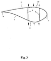
- Fig. 3 is a schematic cross-section of a wind turbine blade 1 having a shell 2 with leading edge 3 and trailing edge 4.
- the wind turbine blade 1 has a box profile with two girders 5 and caps 10 and 11 of the shell 2 located between the girders.
- the aerodynamic and inertia forces working on a blade in operation induce a bending moment on the blade and create a crushing pressure indicated by arrows B.
- the crushing pressure is also referred to as the Brazier effect (reference is made to the article " Structural testing and numerical simulation of a 34 m composite wind turbine blade" by F. M. Jensen et.al. published by Elsevier in Composite Structures 76 (2006) 52-61 ).
- Plate 24b connects to upper right corner 35 with a first surface of plate 24a and is connected to the surface of plate 24a at connection 38.
- Plate 24c connects the lower left corner 34 of the box profile with a second side of plate 24a and is connected to the other surface of plate 24a at connection 39.
- the plates 24b and 24c are substantially aligned and co-operate to connect the opposite set of corners 34, 35 of the box profile.
- the X-shaped reinforcing member further comprises anchors 41 for connection with the respective corners 32-35. In the illustrated embodiment, the anchors 41 are bonded to the inner surface of the box profile.
- the plates 24a - c are received between two receiving surfaces 42 of the anchors and the plates 24a - c are bonded or adhered to the anchors 41. Similar anchors are provided at connections 38 and 39.
- Fig. 8 is a schematic cross-section of a wind turbine blade 20 with a straight reinforcing member 47.
- the two girders 21 and thickened cap parts 22 and 23 of the blade constitute a box profile.
- the box profile is reinforced with a single straight reinforcing member 47 in the form of plate 47.
- Plate 47 is a sandwich construction with outer layers 48 of fibre reinforced plastic on both sides of a foamed material 49.
- the straight reinforcing member 47 has feet 50 providing connection surfaces for bonding the member 47 to the respective girder 21 and part 25, 26 of the shell.
- the feet 50 are bonded to respective flanges of the girders 21 as well as to inner surfaces of the respective shell parts 25 and 26 so that the straight reinforcing member 47 connects corners 34 and 35 of the box profile.
- the plate 47 may provide reinforcement against tension forces and compression forces.
- An embodiment of the invention was analysed with respect to increased strength as compared to a conventional wind turbine blade using numerical modelling of a 34 m wind turbine blade designed for use on a 1.5 MW wind turbine.
- the numerical analysis included Finite Element analysis of a model containing more than 150 000 shell and 3D elements. Advanced software and algorithms were used In the analysis to account for the effect of nonlinear geometrical deformations.
- the model of the blade has been verified with full-scale test of the blade (" Structural testing and numerical simulation of a 34 m composite wind turbine blade" by F. M. Jensen et. al. published by Elsevier In Composite Structures 76 (2006) 52-61 ).
- the blade was loaded with a combination of loads in both flapwise and edgewise direction that should simulate the operational loads of the blade.
- Figs. 11 and 12 show the results of the analysis of a sector near the root of the blade.
Description
- The present invention relates to a reinforced blade for a horizontal-axis wind turbine, particularly to a blade having reinforcing members for reinforcing one or more structural members In the blade in order to prevent transverse shear distortion of the blade when it is loaded In operation.
- Typically, a wind turbine blade has an aerodynamic shell and a girder, such as a beam or a spar. The girder can be a single beam, but often two girders are used. The two girders together with the parts of the shell extending between the two girders form a so-called box profile. The top and bottom of the box profile are often referred to as the caps. Some types of blades are designed with a spar in the form of a box profile which is manufactured separately and bonded in between prefabricated surface shells. The aerodynamic shell is typically made of a laminate of fibre reinforced plastics, fibreglass and/or other materials. Typically, the aerodynamic shell is made from two shell parts that are assembled to form the shell.
- Under normal operation conditions, the wind turbine blade is subjected to loads at an angle to the flapwise direction. It is common to resolve this load on the blade into its components in the flapwise and edgewise direction. The flapwise direction is a direction substantially perpendicular to a transverse axis through a cross-section of the blade. The flapwise direction may thus be construed as the direction, or the opposite/reverse direction, in which the aerodynamic lift acts on the blade. The edgewise loads occur In a direction perpendicular to the flapwise direction. The blade is further subject to torsional loads which are mainly aerodynamic and inertia loads. These loads can subject the blade to harmonic motions or oscillations at the blade's torsional eigenfrequency; cf.
Fig. 1 for an indication of the loads and the directions. - During operation of the blade, transverse shear forces are generated In the blade by the flapwise and edgewise loads. The transverse shear forces are indicated on a typical cross-section of the blade shown in
Fig 2a . The transverse shear forces are induced by the flapwise and edgewise loads because of the typical asymmetric geometry and material distribution of the blade. Further, the fact that the flapwise and edgewise loads do not act through the shear centre of the blade contributes to the generation of transverse shear forces. - In a box profile, the transverse shear forces result in high in-plane bending moments in the corners of the box profile. The bending moments may be counteracted by increasing the thickness of the box profile material in the corners, but increased thickness adversely affects the weight of the blade without a justifying contribution to the strength.
- In wind turbine blades where the girders are manufactured separately and bonded to the shell parts, restraints in the manufacturing process result in small material thicknesses in the section of the girder that is connected to the shell part and therefore this part of the blade has a low bending stiffness.
- The low bending stiffness of the corners of the box profile combined with the high bending moments in the same area, means that the box profile is easily distorted by transverse shear forces, despite the fact that the side, top and bottom of the box profile may be relatively thick.
- An example of the result of the transverse shear distortion caused by the transverse shear forces is shown in
Fig. 2b . The distortion consequently changes the shape of the blade and this has an adverse effect on the blade's ultimate strength. If the transverse shear distortion exceeds a certain limit which depends on the geometry and the material distribution of the blade, the blade's resistance to crushing pressure is reduced and a sudden collapse of the blade can occur. The crushing pressure is caused by the flapwise loads and occurs in the box profile of the blade due to its longitudinal curvature. This effect is also often referred to as ovalization, c.f.Fig. 3 . For a further explanation of the effects of crushing pressure, reference is made to the article "Structural testing and numerical simulation of a 34 m composite wind turbine blade" by F. M. Jensen et.al. published by Elsevier in Composite Structures 76 (2006) 52-61. - Furthermore, a deformation of the girder at the connection between the girder and the shell can lead to fatigue failure of the girder or fatigue failure in the connection between the girder and the shell or both.
-
US 4,976,587 discloses a wind turbine blade comprising a shell, a first girder and a second girder, and two reinforcing members spanning the length of the blade for inhibiting transverse shear distortion of the blade, wherein each of the reinforcing members is connected to a respective one of the first and second girder at a connection between the respective girder and the shell at both the upper part and lower part of the shell and wherein the each of the reinforcing members forms a C-shaped angle bar abutting the respective girder and with legs abutting the upper part and lower part, respectively, of the shell. - Another horizontal-axis wind turbine blade is disclosed in
US 4 339 230 . - Thus, there is a need for a wind turbine blade in which the structural layout of the blade profile is designed against transverse shear distortion and wherein the blade structure is generally strengthened without increasing the overall weight. It is further desirable to provide a wind turbine blade with an increased torsional stiffness.
- It is therefore an object of the invention to provide a wind turbine blade that is designed against transverse shear distortion by transverse shear forces caused by flapwise and edgewise loads on the blade.
- It is also an object of the present invention to provide a reinforced blade profile for a wind turbine blade.
- It is a further object to provide a wind turbine blade with an increased torsional stiffness which will decrease the dynamic inertia loads of the blade on the other structural parts of the wind turbine, such as the gearbox and the tower.
- It is therefore an object of the present Invention to provide a wind turbine blade with improved resistance against deformations of the blade profile.
- It is yet another object of the present invention to provide a wind turbine blade with increased overall strength and stiffness.
- It is yet another object of the present invention to provide a wind turbine blade with increased resistance to fatigue failure.
- It is yet another object of the present invention to provide a wind turbine blade, which can be produced at a reduced manufacturing cost compared to the existing solutions.
- It is still another object of the invention to provide wind turbine blade capable of working under severe aerodynamic loads and to optimize the aerodynamic stability, e.g. aeroelastic stability of the blade.
- It is further an object of the present invention to provide alternatives to the prior art.
- According to a first aspect of the invention, the above-mentioned and other objects are fulfilled by a horizontal-axis wind turbine blade according to
claim 1. - According to a second aspect of the invention, the above-mentioned and other objects are fulfilled by a method according to claim 12.
- A horizontal-axis wind turbine blade having a reinforcing member according to the present invention reduces the transverse shear distortion of the profile and thus increases the blade's resistance to the crushing pressure and thereby increases the ultimate strength of the wind turbine blade. Furthermore, the aerodynamic efficiency of the blade Is also improved since the designed shape of the blade profile is maintained to a higher degree than for a conventional blade.
- A straight reinforcing member keeps its end connections in substantially mutually fixed positions and thus prevents the distance between the connections from increasing thereby inhibiting transverse shear distortion and thus, strengthening the shell against transverse shear forces.
- Each of the one or more reinforcing members increases the torsional stiffness of the blade. An increase of the torsional stiffness of the blade will also increase the torsional eigenfrequency of the blade and in return decrease the dynamic inertia loads of the blade on other parts of the wind turbine. Furthermore, the Increase In the torsional stiffness improves the aeroelastic stability of the blade significantly.
- The shell of the blade may preferably, but not exclusively, comprise a composite or laminated material. The material may comprise, alone or In any combination, fibreglass, carbon fibres, or other durable and flexible materials typically with a high strength/weight ratio, such as other fibre reinforced plastic materials that may further comprise, at least in part, light-weight metals or alloys. The shell may typically be a laminate or sandwich-construction. The thickness of the shell may vary along its length and width.
- The upper part of the shell has a flat surface and during normal operation of the blade, the upper part of the shell is the suction side of the blade. The lower part of the shell has a more curved surface and during normal operation of the blade, the lower part of the shell is the pressure side of the blade. Thus, the upper part of the shell is also denoted the suction side of the shell, and the lower part of the shell is also denoted the pressure side of the shell.
- At least one girder is provided to primarily strengthen the blade along the longitudinal extension of the blade. A girder may also be referred to as a web. Throughout the present disclosure, the girder or web should be construed as any kind of elongate constructional member capable of taking up loads, such as a beam or a spar, e.g. shaped as an I-profile, preferably made from fibre reinforced plastics or other suitable material. The girder may extend along substantially the entire length of the blade.
- The blade may have two or more separated girders positioned end to end along the longitudinal extension of the blade, especially for facilitating handling or transporting purposes. In principle, any number of girders may be used, however for the sake of simplicity and for keeping the overall weight of the blade as low as possible, one or two girders are preferred.
- The reinforcing member may be subjected to tensile and compressive forces when the blade is loaded. To prevent the reinforcing member from buckling when subjected to compression forces, the member can be stiffened with flanges on top of the member or stringers on the side. Further, the member may constitute a sandwich construction with a foam material with laminates on each side.
- In a wind turbine blade with one or more straight reinforcing members according to the invention, a first end of the reinforcing member is connected to the girder in a position identical with, or near or adjacent to where the girder itself is connected to one of the two shell parts. Thus, the reinforcing member is connected to the first girder at a connection between the first girder and the shell at one of the upper part and lower part of the shell. Further, a second, opposite end of each of the straight reinforcing members may be connected to an inner surface of the other shell part. The connection on the inner surface of the shell may in principle be positioned anywhere provided that the reinforcing member exerts a reasonable and useful reinforcing effect in the blade at the selected position.
- Preferably, but not exclusively, the straight reinforcing member may be connected at an angle of 15° - 75° in relation to the girder.
- In a wind turbine blade with two or more girders, each of the one or more straight reinforcing members may be positioned in such a way that it connects not only an inner surface on one of the upper and lower shell parts with one girder, but also Interconnects two girders. Preferably, each of the one or more reinforcing members is positioned so that it interconnects two girders and respective inner surfaces of both of the shell parts.
- When two or more girders are provided, each of the one or more reinforcing members may connect two girders, but may not be connected to respective inner surfaces of the upper and lower shell parts. Thereby, the assembly of the reinforced wind turbine blade may be made particularly simple or may comprise separate manufacturing or assembling steps.
- The connections between reinforcing members and respective girders may comprise any suitable kind of joint such as welded, adhered, melted, bonded, fused or simple mechanical connections.
- When the one or more reinforcing members are connected to an inner surface of the shell parts, such connections are preferably bonded connections.
- The straight reinforcing member has a substantially straight shape, such as the shape of a rod or a stretched wire or a planar member. If the shape of the reinforcing member is not straight, the shape of the reinforcing member could be straightened when subjected to tension leading to movement of its end connections and obviously, this is not desired.
- The connections on the inner surface of the profile may in principle be positioned anywhere on the inner surface but it should be observed that the chosen positioning causes the reinforcing member to be able to provide a reasonable and useful reinforcing effect in the profile. The connection of a reinforcing member to connecting points on the inner surface of the profile prevents the negative effects of buckling and ovalization as described above. The connections may comprise any suitable kind of joint such as welded, glued, melted, fused or other simple mechanical connections. The reinforcing member itself may comprise the connections or it may comprise additional connections or connection parts adapted to engage or cooperate with the connections on the inner surface of the profile. The additional connections or connection parts must be sufficiently rigid to maintain their shape when subjected to tension in order to properly cooperate with the reinforcing member to prevent the connections on the shells from being displaced away from each other. The reinforcing member may be connected to an inner surface of the shell of the profile. Preferably, the inner surface of the shell is shaped in a manner corresponding to the outer surface thereof, i.e. having a substantially transverse curvature. The reinforcing member may therefore preferably be so positioned on the inner surface of the shell that there will be a certain space (or distance) between the reinforcing member and the inner surface of the profile.
- The reinforcing member secures and keeps the transverse curvature of the profile substantially unchanged when the aerodynamic profile is loaded by forces in the flapwise direction. With the reinforcing member according to the invention, the dimensions of the shell may be reduced compared to the prior art leading to reduced loading of other parts of the wind turbine, improved handling and transportation characteristics of the blade and reduced cost.
- In an embodiment of the invention with a box profile, each of the one or more straight reinforcing members connects two diagonally opposite corners or corner regions of the box profile. A corner region is a region proximate and including the connection of the respective girder to the respective shell surface. In other words, the unwanted distortion of the blade caused by transverse shear forces may be reduced or prevented by maintaining corners, or regions near the corners, of the box profile in fixed positions with relation to each other. This improves the overall strength of the blade and may also facilitate the design of a blade with lower overall weight.
- Two or more straight reinforcing members may be positioned end to end or in spaced relationship along a longitudinal axis of the blade in such a way that neighbouring reinforcing members alternates between diagonally opposite corners, or corner regions, in the box profile along at least a part of the longitudinal extension of the blade. Thus, a first reinforcing member extends between two diagonally opposed corners of the box profile and a second neighbouring reinforcing member extends between the opposite two diagonally opposed corners of the box profile. A third reinforcing member adjacent the second reinforcing member extends between two opposed corners along substantially the same direction as the extension of the first reinforcing member.
- Throughout the present disclosure, two diagonally opposite corners connected by a reinforcing member is referred to as a set of corners.
- A reinforcing member may comprise one or more elements selected from the group consisting of rods, plates, wires, ropes, tubes, textiles and fabrics. The reinforcing members may be made of any suitable material. Fibre reinforced plastic is presently preferred for rods, plates and tubes. If a rod, plate or tube type element is provided, such element may be subdivided into two or more smaller reinforcing elements over the span between the set of corners. Such smaller elements may be connected to each other or they may be connected to one or more other reinforcing members spanning the other two opposed corners of the box profile. The reinforcing members may be connected to the girders, to the inner surfaces of the shell parts, and to each other by bonding means or mechanical means.
- The reinforcing member may comprise a plate possibly with one or more cut-outs, e.g. a laminated plate, such as a sandwich construction, preferably, but not exclusively, comprising a layer of a lightweight foamed material provided between two layers of a fibre reinforced plastic material.
- In an embodiment of the invention, two or more straight reinforcing members are provided and arranged at a distance from the outer extremities of each other not exceeding 2xD, wherein D is the spanning distance of one of the reinforcing members, i.e. the distance between two opposing connections of the straight reinforcing member, e.g. between a set of corners in a box profile. The value of parameter D may be identical for two or more neighbouring straight reinforcing members. However, since the width of the cross-section of the wind turbine blade typically decreases towards the tip of the blade, the distance D2 of a reinforcing member located doser to the tip will be smaller than the distance D1 of a reinforcing member located closer to the hub of the wind turbine. The resulting maximum distance between two neighbouring reinforcing members may preferably be calculated based on the minimum of the two distances, i.e. distance D2, or based on the mean value of D1 and D2. It has been found that values of the resulting distance D fulfilling this relationship, there is a good balance between the reinforcing members' ability to take up the shear forces, the total weight of the wind turbine blade and the blade's stiffness. However, the maximum distance between two reinforcing members may in stead be based on other requirements, such as, but not limited to, a need for a particularly strong wind turbine blade design, e.g. when the wind turbine is intended to be subjected to repeatedly severe weather conditions, such as when erected at open sea.
- Two or more reinforcing members may be positioned in certain sections of the blade only, possibly without any predetermined or calculated maximum distance.
- In a blade with two or more reinforcing members, the members may be of the same type or may have different geometries, and possibly may be made from different materials. The members may be positioned so that they span the same two opposed corners, e.g. along the longitudinal extension of the blade, or they may alternate between the sets of opposed corners.
- The reinforcing members may be located in positions wherein a substantial transverse distortion of the blade is expected or established.
- In an embodiment of the invention, two reinforcing members may constitute the legs of an X-shaped reinforcing member, e.g. produced as an integral member, and Interconnecting the upper part of the shell with the lower part of the shell at the respective connection points of the girders to the upper and lower parts of the shell.
- The X-shaped reinforcing member may be made from two straight reinforcing members that are assembled to form the X-shaped reinforcing member. The X-shaped reinforcing member may preferably be assembled from plates of a fibre reinforced plastic material laminated to each other. Feet may be provided at the ends of the individual straight reinforcing members forming the legs of the X-shaped member, the feet facilitating connection, particularly by bonding means, to the respective surfaces of the shell or girder or both of the blade. However, the connections may be obtained in other ways, such as by secondary lamination, mechanical connection means, etc, or any combination of such connection measures.
- Further, the X-shaped member may be made in one piece. The ends of the legs of the single pieced X-shaped member may preferably be connected with the girders by bonding. Bonding may be performed prior to connection of the girders to the inner surfaces of the blade shell. However, the reinforcing member and the girders may also be provided as a single integrated member, preferably of a fibre reinforced plastic, that is connected to the shell parts.
- When two or more X-shaped reinforcing members are provided, the members may be positioned in certain sections of the blade only and not at any predetermined or calculated distance. Particularly, but not exclusively, the X-shaped members may be located at positions wherein a substantial transverse distortion of the blade is expected or established.
- During operation of the blade, only one of the legs of the X-shaped member may be subjected to a load, and this leg will be subjected to tension only whereby the material of the reinforcing member is utilized to a high degree, thus reducing the required material thickness of the member and consequently keeping the total weight of the blade at a minimum.
- Assembly of a wind turbine blade with X-shaped members may be facilitated by assembly of the X-shaped members and the girders before assembly with the shell parts, or by manufacturing the X-shaped members and the girders in one piece, thus facilitating at least a better quality control of the parts during assembly.
- A wind turbine blade with X-shaped members, a cavity may be provided between a member and a respective girder or the inner surface of a shell part. In order to facilitate the assembly of the reinforcing member with the girders or with the shell parts or with both, the cavity may be filled with a lightweight foamed material to facilitate positioning of the X-shaped member.
- The wind turbine blade t may be designed so that shear distortion occurs in one direction only so that a straight reinforcing member can be positioned so that it will be subjected to tension only.
- The direction of shear distortion may be controlled by proper orientation of the layers of fibre reinforced plastic of the shell substantially in a single specific direction, or by proper positioning of the one or more girders in the blade, or by positioning the one or more girders at a specific angle in relation to the flapwise direction, or any combination of such measures.
- A straight reinforcing member that is positioned so that it will be subjected to tension only keeps its end connections in substantially mutually fixed positions and thus prevents the distance between the connections from increasing thereby strengthening the shell against forces in the flapwise direction. Since the reinforcing member is required to have a high tensional strength only, i.e. the reinforcing member need not carry other loads; the reinforcing member is preferably thin so that its weight and cost are kept at a minimum.
- Even though a straight reinforcing member may be subjected to tension only, the member may as well be capable of withstanding compression forces, e.g. the member may comprise a tube or a plate of a laminated or sandwiched construction that is capable of withstanding compression forces.
- The one or more reinforcing members may be individually designed so that the bending and torsion of the blade is coupled to withstand the high loads of strong wind gusts. This leads to lower fatigue loads on the blade and also facilitate a higher energy output of the wind turbine. The individual design may include pre-tensioning of some of the reinforcing members.
- Each of the reinforcing members may comprise one or more electro-mechanical transducers, such as piezoelectric transducers, that may change the extension of respective reinforcing members in certain directions in response to an individual control signal, such as a voltage, a current, an electric field, or a magnetic field, e.g. for imposing stresses on the members coupling the bending and torsion of the blade.
- Below the invention will be described in more detail with reference to the exemplary embodiments illustrated in the drawings, wherein
- Fig. 1
- schematically illustrates in perspective a wind turbine blade and arrows indicating the directions of flapwise, edgewise, and torsional loads, respectively,
- Fig. 2a
- is a schematic cross-section of a wind turbine blade with arrows indicating directions of transverse shear forces in the blade,
- Fig. 2b
- schematically illustrates deformation of a cross-section of a wind turbine blade caused by transverse shear forces,
- Fig. 3
- is a schematic cross-section of a wind turbine blade with arrows indicating crushing pressure on the blade,
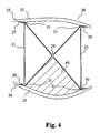
- Fig. 4
- is a schematic cross-section of a wind turbine blade with an X-shaped reinforcing member interconnecting two girders and the upper and lower part of the shell,
- Fig. 5
- is a schematic cross-section of a wind turbine blade with another X-shaped reinforcing member interconnecting two girders,
- Fig. 6
- is a schematic cross-section of a wind turbine blade with yet another X-shaped reinforcing member interconnecting two girders and the upper and lower part of the shell,
- Fig. 7
- is a schematic cross-section of a wind turbine blade with still another X-shaped reinforcing member interconnecting two girders and the upper and lower part of the shell,
- Fig. 8
- is a schematic cross-section of a wind turbine blade with a straight reinforcing member,
- Fig. 9
- schematically illustrates in perspective a wind turbine blade with part of the shell surface removed for making visible an internally positioned plurality of straight reinforcing members extending along crossing directions,
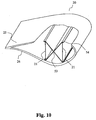
- Fig. 10
- schematically illustrates In perspective a wind turbine blade with part of the shell surface removed for making visible internally positioned two girders connected by an X-shaped reinforcing member extending along the longitudinal extension of the blade,
- Fig. 11
- shows the deformation of a conventional wind turbine blade at a sector near the root of the blade, and
- Fig. 12
- shows the deformation of a wind turbine blade according to the invention at a sector near the root of the blade.
- The figures are schematic and simplified for clarity, and they merely show details which are essential to the understanding of the invention, while other details have been left out. Throughout, the same reference numerals are used for identical or corresponding parts.
- The present invention will now be described more fully hereinafter with reference to the accompanying drawings, in which exemplary embodiments of the invention are shown.
-
Fig. 1 schematically illustrates In perspective awind turbine blade 1 and arrows indicating the directions of flapwise F, edgewise E, and torsional T loads, respectively. The cross-section S1 is shown inFigs. 2a +2b. -
Fig. 2a is a schematic cross-section S1 of a wind turbine blade and arrows indicating directions C of transverse shear forces in the blade, -
Fig. 2b schematically illustrates deformation of a cross-section S1 of awind turbine blade 1 caused by transverse shear forces. The illustratedblade 1 is twisted clockwise by the transverse shear forces. -
Fig. 3 is a schematic cross-section of awind turbine blade 1 having ashell 2 with leadingedge 3 and trailingedge 4. Thewind turbine blade 1 has a box profile with twogirders 5 and caps 10 and 11 of theshell 2 located between the girders. The aerodynamic and inertia forces working on a blade in operation induce a bending moment on the blade and create a crushing pressure indicated by arrows B. The crushing pressure is also referred to as the Brazier effect (reference is made to the article "Structural testing and numerical simulation of a 34 m composite wind turbine blade" by F. M. Jensen et.al. published by Elsevier in Composite Structures 76 (2006) 52-61). -
Fig. 4 is a schematic cross-section of awind turbine blade 20 with an X-shaped reinforcingmember 24 interconnecting twogirders 21 and the upper thickenedcap part 22 and the lower thickenedcap part 23 of the shell. The twogirders 21 and thickenedcap parts member 24. In the illustrated embodiment, the reinforcingmember 24 is connected to both of thegirders 21 and to the inner surfaces of both the upper andlower parts parts member 24 comprisesfeet 31 each of which provides a large surface for bonding with therespective girder 21 andpart member 24 is made in one piece. Each leg of the X-shaped reinforcing member constitutes a straight reinforcing member. A foamedmaterial 40 is located in the cavity between themember 24 and the inner surface of thecap 23. In the illustrated embodiment, the shape of the foamedmaterial 40 matches the shape of the cavity whereby thematerial 40 may guide the positioning of themember 24 during assembly of the blade. -
Fig. 5 is a front view of a box profile of awind turbine blade 20 according to an embodiment of the invention. The box profile comprises twogirders 21 and thickenedcaps rods Fig. 5 , therod 24a is positioned in front of therod 24b. In the illustrated embodiment, the positions of the individual straight reinforcingmembers Fig. 5 , therod 24a connects the upperleft corner 32 of the box profile with the lowerright corner 33 of the box profile. Therod 24b connects the upperright corner 35 with the lowerleft corner 34 of the box profile. It should be noted that therods rods respective girders 21 proximate the inner surfaces of therespective shell parts members girders 21. In the illustrated embodiment, the reinforcingmembers 24 are mechanically connected to thegirders 21 by leadingrods girders 21 and fastening them by means of amechanical connection 36, such as a nut engaging with a threaded section of the end part of therods girders 21 further have retainingmembers 37 for guiding and supporting theconnection 36. -
Fig. 6 is a schematic cross-section of awind turbine blade 20 with yet another X-shaped reinforcingmember 24 interconnecting twogirders 21 and the upper andlower caps girders 21 and thickenedcap parts member 24 comprising two straight reinforcing members constituting the legs of the X-shaped member.Plate 24a constitutes one of the straight reinforcing members, andplates Plate 24a connects the upperleft corner 32 with the lowerright corner 33 of the box profile.Plate 24b connects to upperright corner 35 with a first surface ofplate 24a and is connected to the surface ofplate 24a atconnection 38.Plate 24c connects the lowerleft corner 34 of the box profile with a second side ofplate 24a and is connected to the other surface ofplate 24a atconnection 39. Theplates corners anchors 41 for connection with the respective corners 32-35. In the illustrated embodiment, theanchors 41 are bonded to the inner surface of the box profile. Theplates 24a - c are received between two receivingsurfaces 42 of the anchors and theplates 24a - c are bonded or adhered to theanchors 41. Similar anchors are provided atconnections -
Fig. 7 is a schematic cross-section of awind turbine blade 20 with still another X-shaped reinforcingmember 24 interconnecting twogirders 21 and theupper part 25 and thelower part 26 of the shell. The twogirders 21 and thickenedcaps member 24 is made of twoangle plates Angle plates angle plates feet 44 and aprojection 45 facilitating connection of theangle plates feet 44 ofangular plates girders 21 and to inner surfaces of theshell parts projections 45 of the angular plates are bonded to each other at theconnection 46. Further a foamedmaterial 40 is provided, e.g., in a cavity defined betweenangular plate 43a and thegirder 21. The foamedmaterial 40 has a shape that matches the shape of the cavity and is used for guiding positioning of theplate member 43a during assembly. -
Fig. 8 is a schematic cross-section of awind turbine blade 20 with a straight reinforcingmember 47. The twogirders 21 and thickenedcap parts straight reinforcing member 47 in the form ofplate 47.Plate 47 is a sandwich construction withouter layers 48 of fibre reinforced plastic on both sides of a foamedmaterial 49. The straight reinforcingmember 47 hasfeet 50 providing connection surfaces for bonding themember 47 to therespective girder 21 andpart feet 50 are bonded to respective flanges of thegirders 21 as well as to inner surfaces of therespective shell parts member 47 connectscorners plate 47 may provide reinforcement against tension forces and compression forces. -
Fig. 9 schematically illustrates in perspective awind turbine blade 20 with part of the shell surface removed for making visible an internally positioned plurality of straight reinforcingmembers blade 20 is reinforced with two straight reinforcingmembers member 47 shown inFig. 8 , i.e. each of the reinforcingmembers members blade 20. It is seen that the first reinforcingmember 51 extends between two diagonally opposed corners of the box profile and the secondneighbouring reinforcing member 52 extends between the other two diagonally opposed corners of the box profile. -
Fig. 10 schematically illustrates In perspective awind turbine blade 20 with part of the shell surface removed for making visible internally positioned twogirders 21 connected by an X-shaped reinforcingmember 53 extending along the longitudinal extension of theblade 20. Theblade 20 is reinforced with an X-shaped reinforcingmember 53 connecting the corners of the box profile. The straight reinforcingmember 53 is made In one piece and hasfeet 54 connected to flanges of thegirders 21. The straight reinforcingmember 53 andgirders 21 are assembled before connection with theshell parts - An embodiment of the invention was analysed with respect to increased strength as compared to a conventional wind turbine blade using numerical modelling of a 34 m wind turbine blade designed for use on a 1.5 MW wind turbine.
- The numerical analysis included Finite Element analysis of a model containing more than 150 000 shell and 3D elements. Advanced software and algorithms were used In the analysis to account for the effect of nonlinear geometrical deformations.
- The model of the blade has been verified with full-scale test of the blade ("Structural testing and numerical simulation of a 34 m composite wind turbine blade" by F. M. Jensen et. al. published by Elsevier In Composite Structures 76 (2006) 52-61). The blade was loaded with a combination of loads in both flapwise and edgewise direction that should simulate the operational loads of the blade.
- The analysis showed a significant reduction of transverse shear distortion when the blade Is equipped with the invention.
Figs. 11 and 12 show the results of the analysis of a sector near the root of the blade. - The analysis shows a reduction of the transverse shear distortion of the profile and this increase the blade's resistance to the crushing pressure and thereby increases the ultimate strength of the wind turbine blade.
- Furthermore, the aerodynamic efficiency of the blade is also improved since the designed shape of the blade profile is maintained to a higher degree than for a conventional blade.
Claims (12)
- A horizontal-axis wind turbine blade (20) comprising
a shell,
a first girder (21) connected to an upper part (25) and a lower part (26) of the shell, and characterized in that
a straight reinforcing member (24) for inhibiting transverse shear distortion of the blade (20) is located in a transverse cross-section of the blade and is connected tothe first girder (21) at a connection between the first girder (21) and the shell at one of the upper part (25) and lower part (26) of the shell, and connected tothe other one of the upper part (25) and lower part (26) of the shell at a distance from the girder (21). - A horizontal-axis wind turbine blade (20) according to claim 1, further comprising a second girder (21) and wherein the reinforcing member (24) is a first straight reinforcing member (24) interconnecting the first and second girders (21) between a connection between the first girder (21) and the shell at one of the upper part (25) and lower part (26) of the shell and a connection between the second girder (21) and the shell at the other one of the upper part (25) and lower part (26) of the shell.
- A horizontal-axis wind turbine blade (20) according to claim 2, further comprising a second straight reinforcing member (24) interconnecting the first and second girders (21) between a connection between the first girder (21) and the shell at the one of the upper part (25) and lower part (26) of the shell that is opposite the connection of the first straight reinforcing member (24) to the first girder (21) and a connection between the second girder (21) and the shell at the other one of the upper part (25) and lower part (26) of the shell whereby the first and second straight reinforcing members (24) form a cross in a transverse cross-section of the blade.
- A horizontal-axis wind turbine blade (20) according to claim 3, wherein the first and second straight reinforcing members form an X-shaped reinforcing member (24) interconnecting the upper part (25) of the shell with the lower part (26) of the shell at the respective connection points of the girders (21) to the upper and lower parts (25, 26) of the shell.
- A horizontal-axis wind turbine blade according to claim 4, wherein the X-shaped reinforcing member (24) is made in one piece.
- A horizontal-axis wind turbine blade (20) according to claim 5, wherein the X-shaped reinforcing member (24) and the girders (21)are provided as a single integrated member.
- A horizontal-axis wind turbine blade (20) according to any of claims 3-6, wherein the girders (21) form a box profile and the straight reinforcing member (24) connects two diagonally opposite corner regions (32, 33; 34, 35) of the box profile.
- A horizontal-axis wind turbine blade (20) according to any of the preceding claims, wherein the straight reinforcing member (24) comprises at least one element selected from the group consisting of a plate, a rod (24a, 24b) a wire, a rope, a tube, a textile and a fabric.
- A horizontal-axis wind turbine blade (20) according to any of the preceding claims, comprising a plurality of straight reinforcing members (24) positioned in spaced relationship along the longitudinal extension of the blade (20) with a mutual distance that is less than 2xD, wherein D is the distance of opposing connections of one of the plurality of straight reinforcing members (24) to the upper part (25) and lower part (26) of the shell, respectively.
- A horizontal-axis wind turbine blade (20) according to any of the preceding claims, wherein at least one reinforcing member comprises a laminated plate (47).
- A horizontal-axis wind turbine blade (20) according to claim 10, wherein the laminated plate (47) is a sandwich construction.
- A method of inhibiting transverse shear distortion in a horizontal-axis wind turbine blade (20) according to claim 1 comprising a shell, and a first girder (21) wherein the first girder (21) is connected to an upper part (25) of the shell and a lower part (26) of the shell,
characterized in that the method comprises the steps of
providing a straight reinforcing member (24) with a first end and a second opposite end, and
connecting in a transverse cross-section of the blade the first end to the first girder (21) at the connection between the first girder (21) and the shell at the upper part (25) or the lower part (26) of the shell,
and connecting the second end to the opposite part of the shell at a distance from the girder (21).
Applications Claiming Priority (2)
| Application Number | Priority Date | Filing Date | Title |
|---|---|---|---|
| DKPA200700118 | 2007-01-25 | ||
| PCT/DK2008/000032 WO2008089765A2 (en) | 2007-01-25 | 2008-01-25 | Reinforced blade for wind turbine |
Related Child Applications (1)
| Application Number | Title | Priority Date | Filing Date |
|---|---|---|---|
| EP11190778.8 Division-Into | 2011-11-25 |
Publications (2)
| Publication Number | Publication Date |
|---|---|
| EP2108083A2 EP2108083A2 (en) | 2009-10-14 |
| EP2108083B1 true EP2108083B1 (en) | 2012-11-07 |
Family
ID=39580166
Family Applications (1)
| Application Number | Title | Priority Date | Filing Date |
|---|---|---|---|
| EP08700903A Active EP2108083B1 (en) | 2007-01-25 | 2008-01-25 | Reinforced blade for wind turbine |
Country Status (6)
| Country | Link |
|---|---|
| US (1) | US8632312B2 (en) |
| EP (1) | EP2108083B1 (en) |
| CN (1) | CN101589227B (en) |
| DK (1) | DK2108083T3 (en) |
| ES (1) | ES2399158T3 (en) |
| WO (1) | WO2008089765A2 (en) |
Cited By (1)
| Publication number | Priority date | Publication date | Assignee | Title |
|---|---|---|---|---|
| WO2015024573A1 (en) * | 2013-08-20 | 2015-02-26 | Bladena Aps | A wind turbine, a wind turbine blade, and a method of reinforcing a wind turbine blade |
Families Citing this family (47)
| Publication number | Priority date | Publication date | Assignee | Title |
|---|---|---|---|---|
| EP2094967B1 (en) * | 2006-12-15 | 2012-10-24 | Bladena ApS | Reinforced aerodynamic profile |
| ES2496167T3 (en) * | 2007-01-16 | 2014-09-18 | Bladena Aps | Reinforced wind turbine blade |
| DK2108083T3 (en) | 2007-01-25 | 2013-02-04 | Bladena Aps | Reinforced wind turbine blade |
| WO2008092451A2 (en) * | 2007-01-29 | 2008-08-07 | Danmarks Tekniske Universitet | Wind turbine blade |
| WO2009155921A1 (en) * | 2008-06-23 | 2009-12-30 | Danmarks Tekniske Universitet | A wind turbine blade with angled girders |
| WO2009155920A1 (en) | 2008-06-24 | 2009-12-30 | Danmarks Tekniske Universitet | A reinforced wind turbine blade |
| GB2467745A (en) * | 2009-02-11 | 2010-08-18 | Vestas Wind Sys As | Wind turbine blade with tension element(s) to increase edgewise stiffness |
| LU91530B1 (en) * | 2009-02-20 | 2010-08-23 | Constant Seiwerath | Rotor blade production |
| US8079819B2 (en) * | 2009-05-21 | 2011-12-20 | Zuteck Michael D | Optimization of premium fiber material usage in wind turbine spars |
| US8075278B2 (en) * | 2009-05-21 | 2011-12-13 | Zuteck Michael D | Shell structure of wind turbine blade having regions of low shear modulus |
| DK2317124T3 (en) | 2009-10-01 | 2018-10-08 | Vestas Wind Sys As | Wind turbine blade |
| EP2357357B1 (en) | 2009-10-01 | 2016-11-09 | Vestas Wind Systems A/S | Wind turbine blade |
| EP2330294B1 (en) * | 2009-12-02 | 2013-01-16 | Bladena ApS | Reinforced airfoil shaped body |
| US8142164B2 (en) * | 2009-12-31 | 2012-03-27 | General Electric Company | Rotor blade for use with a wind turbine and method for assembling rotor blade |
| WO2012010304A1 (en) | 2010-07-20 | 2012-01-26 | Airbus Operations Gmbh | Lining shell carrying a main load and structural component having at least one lining shell carrying a main load |
| US20110182730A1 (en) * | 2010-07-27 | 2011-07-28 | Vestas Wind Systems A/S | Wind turbine blade with damping element for edgewise vibrations |
| DE102010039705B4 (en) * | 2010-08-24 | 2020-02-27 | Airbus Operations Gmbh | Structural element for an aircraft and spacecraft and method for producing such a structural element |
| DK2441950T3 (en) | 2010-10-15 | 2014-06-10 | Alstom Renovables Espana Sl | Wing for a wind turbine |
| DE102011080869A1 (en) * | 2011-08-12 | 2013-02-14 | Repower Systems Se | Method for producing a rotor blade of a wind energy plant, web package, rotor blade and wind energy plant |
| US20130064677A1 (en) * | 2011-09-13 | 2013-03-14 | General Electric Company | Rotor blade assembly for wind turbine |
| DE102011082664C5 (en) * | 2011-09-14 | 2017-08-10 | Senvion Gmbh | Mold for producing a web and web for a rotor blade of a wind energy plant |
| FR2980514B1 (en) * | 2011-09-23 | 2018-01-05 | Flakt Solyvent-Ventec | ROTATING MACHINE BLADE WITH REINFORCED MODULAR STRUCTURE |
| CN104271941A (en) * | 2011-12-22 | 2015-01-07 | Lmwp专利控股有限公司 | Wind turbine blade assembled from inboard part and outboard part having different types of load carrying structures |
| US9168999B2 (en) * | 2012-04-18 | 2015-10-27 | Hamilton Sundstrand Corporation | Propeller blade with internal stiffener |
| ITCO20120022A1 (en) * | 2012-05-02 | 2013-11-03 | Nuovo Pignone Srl | ROTARY VALVES FOR ALTERNATIVE COMPRESSORS AND RELATED METHODS |
| FR2991206B1 (en) * | 2012-06-01 | 2014-06-20 | Snecma | PROCESS FOR MAKING A METAL REINFORCEMENT OF A TURBOMACHINE BLADE |
| US20140322025A1 (en) * | 2013-04-25 | 2014-10-30 | Wetzel Engineering, Inc. | Structural Member with X-Web |
| WO2015003717A1 (en) * | 2013-07-11 | 2015-01-15 | Vestas Wind Systems A/S | Wind turbine blades |
| US9506452B2 (en) * | 2013-08-28 | 2016-11-29 | General Electric Company | Method for installing a shear web insert within a segmented rotor blade assembly |
| US20150252780A1 (en) * | 2014-03-07 | 2015-09-10 | Siemens Aktiengesellschaft | Wind turbine blade spar web having enhanced buckling strength |
| CN104033339B (en) * | 2014-05-27 | 2017-01-18 | 上海通用风机股份有限公司 | Wind turbine blade |
| GB2527587A (en) * | 2014-06-27 | 2015-12-30 | Vestas Wind Sys As | Improvements relating to wind turbine blade manufacture |
| CA2957087A1 (en) * | 2014-08-26 | 2016-03-03 | Bladena Solutions Aps | A wind turbine blade, and a method of reinforcing a wind turbine blade |
| GB201419681D0 (en) | 2014-11-05 | 2014-12-17 | Rolls Royce Plc | Manufacturing method |
| ES2779753T3 (en) * | 2015-05-20 | 2020-08-19 | Bladena Aps | A wind turbine blade with a stiffening member and a method of installing a stiffening member |
| DK3380721T3 (en) | 2015-11-26 | 2020-02-17 | Vestas Wind Sys As | IMPROVEMENTS RELATED TO THE MANUFACTURE OF WINDMILL EXPERIENCES |
| US10207471B2 (en) * | 2016-05-04 | 2019-02-19 | General Electric Company | Perforated ceramic matrix composite ply, ceramic matrix composite article, and method for forming ceramic matrix composite article |
| CN106050552A (en) * | 2016-07-18 | 2016-10-26 | 国电联合动力技术有限公司 | Fan blade capable of resisting to bending and wind driven generator containing fan blade |
| US10828843B2 (en) * | 2017-03-16 | 2020-11-10 | General Electric Company | Shear webs for wind turbine rotor blades and methods for manufacturing same |
| DK3606731T3 (en) * | 2017-04-05 | 2022-03-07 | Vestas Wind Sys As | IMPROVEMENTS WITH WIND TURBINE WING MANUFACTURE |
| US10544776B2 (en) | 2017-07-27 | 2020-01-28 | General Electric Company | Injection method and device for connecting and repairing a shear web |
| EP3706987B1 (en) | 2017-11-07 | 2023-06-07 | Vestas Wind Systems A/S | Improvements relating to wind turbine blade manufacture |
| WO2019212551A1 (en) * | 2018-05-03 | 2019-11-07 | General Electric Company | Shear webs for wind turbine rotor blades and methods for manufacturing same |
| MX2021002822A (en) | 2018-09-11 | 2022-12-13 | Tpi Composites Inc | Temporary web support for wind turbine blade rotating device. |
| US11046420B2 (en) * | 2019-10-23 | 2021-06-29 | The Boeing Company | Trailing edge flap having a waffle grid interior structure |
| CN110905719A (en) * | 2019-12-02 | 2020-03-24 | 三一重能有限公司 | Wind power blade and wind power generation equipment |
| WO2023126042A1 (en) | 2021-12-29 | 2023-07-06 | Vestas Wind Systems A/S | A wind turbine blade and a method for manufacturing a wind turbine blade |
Family Cites Families (55)
| Publication number | Priority date | Publication date | Assignee | Title |
|---|---|---|---|---|
| FR568874A (en) | 1922-08-21 | 1924-04-03 | Improvements in the construction of lifting surfaces for airplanes | |
| GB319299A (en) | 1928-06-19 | 1929-09-19 | Blasius Bart | Improvements in or relating to hollow internally reinforced structures or structural units |
| FR701140A (en) | 1929-09-26 | 1931-03-12 | Improvements to frames particularly suitable for aircraft construction | |
| FR703261A (en) | 1929-10-26 | 1931-04-28 | Improvements to the wing structure for aircraft | |
| GB909004A (en) | 1957-11-18 | 1962-10-24 | Kurt Axmann | Improvements in or relating to propeller blades |
| FR2286953A1 (en) | 1974-10-03 | 1976-04-30 | Bel Hamri Bernard | Aerostatic rotor for gas engine - produces energy from wind and cold gas and actuates electric generator or water pump |
| IT7967327A0 (en) | 1979-02-15 | 1979-02-15 | Fiat Ricerche | BLADE FOR WIND MOTORS |
| DE2923463A1 (en) | 1979-06-09 | 1980-12-18 | Erich Herter | Blade for wind driven turbine - has outer skin in tension to be load carrying without stiffening framework on inside of blade |
| US4295790A (en) * | 1979-06-21 | 1981-10-20 | The Budd Company | Blade structure for use in a windmill |
| HU178353B (en) | 1979-10-25 | 1982-04-28 | Szelloezoe Muevek | Wing or blade composed from parts for fans or fanlike machines |
| US4339230A (en) * | 1980-04-22 | 1982-07-13 | Hercules Incorporated | Bifoil blade |
| DE3037677A1 (en) | 1980-10-04 | 1982-05-19 | M.A.N. Maschinenfabrik Augsburg-Nürnberg AG, 8000 München | Wind-driven machine rotor wing - has spar formed by axial mast, to which are secured profiled strips via triangular gusset plates |
| DE3113079C2 (en) | 1981-04-01 | 1985-11-21 | Messerschmitt-Bölkow-Blohm GmbH, 8000 München | Large aerodynamic wing and process for its manufacture |
| DE3114567A1 (en) | 1981-04-10 | 1982-10-28 | Messerschmitt-Bölkow-Blohm GmbH, 8000 München | "LARGE ROTOR BLADE" |
| CA1151072A (en) | 1981-07-15 | 1983-08-02 | Lawrence Rowley | Vertical axis wind turbine and curved slender airfoil therefor |
| DK387882A (en) | 1982-02-01 | 1983-08-02 | Stanford Res Inst Int | WIND TURBIN ROTOR SHEET AND PROCEDURE FOR PREPARING THE SAME |
| JPS61192866A (en) | 1985-02-21 | 1986-08-27 | Yamaha Motor Co Ltd | Rotor blade structure of wind mill |
| JPS62282176A (en) | 1986-05-31 | 1987-12-08 | Yamaha Motor Co Ltd | Rotor blade for windmill |
| NL8602097A (en) | 1986-08-18 | 1988-03-16 | Strijense Kunststof Technieken | WIND TURBINE ROTOR WITH TWO ROTOR BLADES. |
| US4976587A (en) * | 1988-07-20 | 1990-12-11 | Dwr Wind Technologies Inc. | Composite wind turbine rotor blade and method for making same |
| GB8907544D0 (en) | 1989-04-04 | 1989-05-17 | Kidd Archibald W | The design of a windmill blade |
| IT219392Z2 (en) | 1990-03-12 | 1993-02-26 | FIXING SYSTEM BETWEEN EXTRUDED BUCKET WITH HOLLOW STRUCTURE FOR AXIAL FAN AND BUCKET LEG INSERTED | |
| NL9100816A (en) | 1991-05-10 | 1992-12-01 | Aerpac Holding B V | Hollow plastic structure-reinforcement method - by joining sections by inflating and hardening adhesive auxiliary plastic structure |
| US5330092A (en) | 1991-12-17 | 1994-07-19 | The Boeing Company | Multiple density sandwich structures and method of fabrication |
| DE4225599A1 (en) | 1992-08-03 | 1994-02-17 | Harald Dr Kayser | Air-foil wing for wind power installation - consists of extruded profile and one or two metal plates of light construction for exploiting average or low wind speeds |
| US5375324A (en) | 1993-07-12 | 1994-12-27 | Flowind Corporation | Vertical axis wind turbine with pultruded blades |
| DE4428730A1 (en) | 1994-08-15 | 1996-02-22 | Biotech Gmbh Zwickau Planungs | Metallic rotor blade for wind powered systems |
| DK173460B2 (en) | 1998-09-09 | 2004-08-30 | Lm Glasfiber As | Windmill wing with lightning conductor |
| ES2178903B1 (en) | 1999-05-31 | 2004-03-16 | Torres Martinez M | SHOVEL FOR AEROGENERATOR. |
| DE19962454A1 (en) | 1999-12-22 | 2001-07-05 | Aerodyn Eng Gmbh | Rotor blade for wind turbines |
| DK174319B1 (en) | 2000-06-20 | 2002-12-02 | Lm Glasfiber As | Wind turbine blade with noise canceling means |
| EP3219981B1 (en) | 2001-07-19 | 2021-09-01 | Vestas Wind Systems A/S | Wind turbine blade |
| DK176335B1 (en) | 2001-11-13 | 2007-08-20 | Siemens Wind Power As | Process for manufacturing wind turbine blades |
| JP2003214322A (en) * | 2002-02-18 | 2003-07-30 | Makku:Kk | Divided construction method of surface finished blade for wind power generation |
| JP2003293937A (en) | 2002-04-03 | 2003-10-15 | Ebara Corp | Blade structure for vertical axis windmill |
| DK175718B1 (en) | 2002-04-15 | 2005-02-07 | Ssp Technology As | Möllevinge |
| DE20206942U1 (en) | 2002-05-02 | 2002-08-08 | Repower Systems Ag | Rotor blade for wind turbines |
| AU2003303991B2 (en) | 2003-03-06 | 2006-12-14 | Vestas Wind Systems A/S | Connection between members |
| AU2003218697A1 (en) | 2003-03-06 | 2004-09-28 | Vestas Wind Systems A/S | Pre-consolidated pre-form and method of pre-consolidating pre-forms |
| DE10336461A1 (en) | 2003-08-05 | 2005-03-03 | Aloys Wobben | Method for producing a rotor blade of a wind energy plant |
| NL1024463C2 (en) | 2003-10-06 | 2005-04-07 | Polymarin Holding B V | Rotor for use in a wind turbine and method for making the rotor. |
| EP1584817A1 (en) | 2004-04-07 | 2005-10-12 | Gamesa Eolica, S.A. (Sociedad Unipersonal) | Wind turbine blade |
| CN1977108B (en) | 2004-06-30 | 2011-09-14 | 维斯塔斯风力系统有限公司 | Wind turbine blades made of two separate sections, and method of assembly |
| ES2249182B1 (en) | 2004-09-14 | 2007-05-01 | Gamesa Eolica S.A. | STRUCTURAL BEAM OF THE WIND OF A WIND AEROGENERATOR AND MANUFACTURING PROCESS OF THE SAME. |
| DK176418B1 (en) | 2004-12-22 | 2008-01-21 | Lm Glasfiber As | Process for producing a fiber-reinforced part for a wind power plant |
| ES2265760B1 (en) | 2005-03-31 | 2008-01-16 | GAMESA INNOVATION & TECHNOLOGY, S.L. | SHOVEL FOR WIND GENERATORS. |
| EP1754589B1 (en) | 2005-08-17 | 2015-10-14 | General Electric Company | Use of continuous laminates, in particular suitable as a spar cap or another part of a wind energy turbine rotor blade |
| DE102005054594A1 (en) | 2005-11-14 | 2007-05-16 | Daubner & Stommel Gbr | Rotor blade for a wind energy plant |
| US7604461B2 (en) | 2005-11-17 | 2009-10-20 | General Electric Company | Rotor blade for a wind turbine having aerodynamic feature elements |
| US7427189B2 (en) | 2006-02-13 | 2008-09-23 | General Electric Company | Wind turbine rotor blade |
| US7517198B2 (en) | 2006-03-20 | 2009-04-14 | Modular Wind Energy, Inc. | Lightweight composite truss wind turbine blade |
| FR2898865B1 (en) | 2006-03-27 | 2008-05-30 | Cetim Cermat Ass Loi De 1901 | AERODYNAMIC OR HYDRODYNAMIC PROFILE THAT CAN BE DEFORMED IN CONTINUOUS AND CONTROLLED MANNER |
| EP1880833A1 (en) | 2006-07-19 | 2008-01-23 | National University of Ireland, Galway | Composite articles comprising in-situ-polymerisable thermoplastic material and processes for their construction |
| ES2496167T3 (en) | 2007-01-16 | 2014-09-18 | Bladena Aps | Reinforced wind turbine blade |
| DK2108083T3 (en) | 2007-01-25 | 2013-02-04 | Bladena Aps | Reinforced wind turbine blade |
-
2008
- 2008-01-25 DK DK08700903.1T patent/DK2108083T3/en active
- 2008-01-25 WO PCT/DK2008/000032 patent/WO2008089765A2/en active Application Filing
- 2008-01-25 EP EP08700903A patent/EP2108083B1/en active Active
- 2008-01-25 US US12/449,064 patent/US8632312B2/en active Active
- 2008-01-25 CN CN200880003279.1A patent/CN101589227B/en active Active
- 2008-01-25 ES ES08700903T patent/ES2399158T3/en active Active
Cited By (2)
| Publication number | Priority date | Publication date | Assignee | Title |
|---|---|---|---|---|
| WO2015024573A1 (en) * | 2013-08-20 | 2015-02-26 | Bladena Aps | A wind turbine, a wind turbine blade, and a method of reinforcing a wind turbine blade |
| US10273934B2 (en) | 2013-08-20 | 2019-04-30 | Bladena Aps | Wind turbine, a wind turbine blade, and a method of reinforcing a wind turbine blade |
Also Published As
| Publication number | Publication date |
|---|---|
| EP2108083A2 (en) | 2009-10-14 |
| US8632312B2 (en) | 2014-01-21 |
| CN101589227A (en) | 2009-11-25 |
| ES2399158T3 (en) | 2013-03-26 |
| DK2108083T3 (en) | 2013-02-04 |
| WO2008089765A3 (en) | 2008-09-18 |
| US20100092300A1 (en) | 2010-04-15 |
| WO2008089765A2 (en) | 2008-07-31 |
| CN101589227B (en) | 2014-11-26 |
Similar Documents
| Publication | Publication Date | Title |
|---|---|---|
| EP2108083B1 (en) | Reinforced blade for wind turbine | |
| US8485786B2 (en) | Reinforced blade for wind turbine | |
| US20110176928A1 (en) | Wind turbine blade with angled girders | |
| US9784240B2 (en) | Reinforced wind turbine blade | |
| US8454318B2 (en) | Reinforced aerodynamic profile | |
| US9416768B2 (en) | Reinforced airfoil shaped body | |
| WO2010000263A2 (en) | A reinforced blade for a wind turbine | |
| KR20110100192A (en) | Wind turbine blade and wind turbine generator using the same | |
| EP3387251B1 (en) | Rotor blade for a wind turbine | |
| CN210622996U (en) | Main beam and blade of wind generating set and wind generating set | |
| GB2484108A (en) | Blade attachment arrangement for a vertical axis wind turbine |
Legal Events
| Date | Code | Title | Description |
|---|---|---|---|
| PUAI | Public reference made under article 153(3) epc to a published international application that has entered the european phase |
Free format text: ORIGINAL CODE: 0009012 |
|
| 17P | Request for examination filed |
Effective date: 20090825 |
|
| AK | Designated contracting states |
Kind code of ref document: A2 Designated state(s): AT BE BG CH CY CZ DE DK EE ES FI FR GB GR HR HU IE IS IT LI LT LU LV MC MT NL NO PL PT RO SE SI SK TR |
|
| 17Q | First examination report despatched |
Effective date: 20091116 |
|
| DAX | Request for extension of the european patent (deleted) | ||
| RIN1 | Information on inventor provided before grant (corrected) |
Inventor name: JENSEN, FIND, MOLHOLT |
|
| GRAP | Despatch of communication of intention to grant a patent |
Free format text: ORIGINAL CODE: EPIDOSNIGR1 |
|
| RAP1 | Party data changed (applicant data changed or rights of an application transferred) |
Owner name: BLADENA APS |
|
| GRAS | Grant fee paid |
Free format text: ORIGINAL CODE: EPIDOSNIGR3 |
|
| GRAA | (expected) grant |
Free format text: ORIGINAL CODE: 0009210 |
|
| AK | Designated contracting states |
Kind code of ref document: B1 Designated state(s): AT BE BG CH CY CZ DE DK EE ES FI FR GB GR HR HU IE IS IT LI LT LU LV MC MT NL NO PL PT RO SE SI SK TR |
|
| REG | Reference to a national code |
Ref country code: GB Ref legal event code: FG4D |
|
| REG | Reference to a national code |
Ref country code: CH Ref legal event code: EP Ref country code: AT Ref legal event code: REF Ref document number: 583124 Country of ref document: AT Kind code of ref document: T Effective date: 20121115 |
|
| REG | Reference to a national code |
Ref country code: IE Ref legal event code: FG4D |
|
| REG | Reference to a national code |
Ref country code: DE Ref legal event code: R096 Ref document number: 602008019935 Country of ref document: DE Effective date: 20130103 |
|
| REG | Reference to a national code |
Ref country code: DK Ref legal event code: T3 |
|
| REG | Reference to a national code |
Ref country code: AT Ref legal event code: MK05 Ref document number: 583124 Country of ref document: AT Kind code of ref document: T Effective date: 20121107 |
|
| REG | Reference to a national code |
Ref country code: ES Ref legal event code: FG2A Ref document number: 2399158 Country of ref document: ES Kind code of ref document: T3 Effective date: 20130326 |
|
| REG | Reference to a national code |
Ref country code: NL Ref legal event code: VDEP Effective date: 20121107 |
|
| REG | Reference to a national code |
Ref country code: LT Ref legal event code: MG4D |
|
| PG25 | Lapsed in a contracting state [announced via postgrant information from national office to epo] |
Ref country code: IS Free format text: LAPSE BECAUSE OF FAILURE TO SUBMIT A TRANSLATION OF THE DESCRIPTION OR TO PAY THE FEE WITHIN THE PRESCRIBED TIME-LIMIT Effective date: 20130307 Ref country code: SE Free format text: LAPSE BECAUSE OF FAILURE TO SUBMIT A TRANSLATION OF THE DESCRIPTION OR TO PAY THE FEE WITHIN THE PRESCRIBED TIME-LIMIT Effective date: 20121107 Ref country code: FI Free format text: LAPSE BECAUSE OF FAILURE TO SUBMIT A TRANSLATION OF THE DESCRIPTION OR TO PAY THE FEE WITHIN THE PRESCRIBED TIME-LIMIT Effective date: 20121107 Ref country code: NO Free format text: LAPSE BECAUSE OF FAILURE TO SUBMIT A TRANSLATION OF THE DESCRIPTION OR TO PAY THE FEE WITHIN THE PRESCRIBED TIME-LIMIT Effective date: 20130207 Ref country code: HR Free format text: LAPSE BECAUSE OF FAILURE TO SUBMIT A TRANSLATION OF THE DESCRIPTION OR TO PAY THE FEE WITHIN THE PRESCRIBED TIME-LIMIT Effective date: 20121107 Ref country code: NL Free format text: LAPSE BECAUSE OF FAILURE TO SUBMIT A TRANSLATION OF THE DESCRIPTION OR TO PAY THE FEE WITHIN THE PRESCRIBED TIME-LIMIT Effective date: 20121107 Ref country code: LT Free format text: LAPSE BECAUSE OF FAILURE TO SUBMIT A TRANSLATION OF THE DESCRIPTION OR TO PAY THE FEE WITHIN THE PRESCRIBED TIME-LIMIT Effective date: 20121107 |
|
| PG25 | Lapsed in a contracting state [announced via postgrant information from national office to epo] |
Ref country code: PL Free format text: LAPSE BECAUSE OF FAILURE TO SUBMIT A TRANSLATION OF THE DESCRIPTION OR TO PAY THE FEE WITHIN THE PRESCRIBED TIME-LIMIT Effective date: 20121107 Ref country code: PT Free format text: LAPSE BECAUSE OF FAILURE TO SUBMIT A TRANSLATION OF THE DESCRIPTION OR TO PAY THE FEE WITHIN THE PRESCRIBED TIME-LIMIT Effective date: 20130307 Ref country code: BE Free format text: LAPSE BECAUSE OF FAILURE TO SUBMIT A TRANSLATION OF THE DESCRIPTION OR TO PAY THE FEE WITHIN THE PRESCRIBED TIME-LIMIT Effective date: 20121107 Ref country code: CY Free format text: LAPSE BECAUSE OF FAILURE TO SUBMIT A TRANSLATION OF THE DESCRIPTION OR TO PAY THE FEE WITHIN THE PRESCRIBED TIME-LIMIT Effective date: 20121107 Ref country code: LV Free format text: LAPSE BECAUSE OF FAILURE TO SUBMIT A TRANSLATION OF THE DESCRIPTION OR TO PAY THE FEE WITHIN THE PRESCRIBED TIME-LIMIT Effective date: 20121107 Ref country code: GR Free format text: LAPSE BECAUSE OF FAILURE TO SUBMIT A TRANSLATION OF THE DESCRIPTION OR TO PAY THE FEE WITHIN THE PRESCRIBED TIME-LIMIT Effective date: 20130208 Ref country code: SI Free format text: LAPSE BECAUSE OF FAILURE TO SUBMIT A TRANSLATION OF THE DESCRIPTION OR TO PAY THE FEE WITHIN THE PRESCRIBED TIME-LIMIT Effective date: 20121107 |
|
| PG25 | Lapsed in a contracting state [announced via postgrant information from national office to epo] |
Ref country code: AT Free format text: LAPSE BECAUSE OF FAILURE TO SUBMIT A TRANSLATION OF THE DESCRIPTION OR TO PAY THE FEE WITHIN THE PRESCRIBED TIME-LIMIT Effective date: 20121107 |
|
| PG25 | Lapsed in a contracting state [announced via postgrant information from national office to epo] |
Ref country code: SK Free format text: LAPSE BECAUSE OF FAILURE TO SUBMIT A TRANSLATION OF THE DESCRIPTION OR TO PAY THE FEE WITHIN THE PRESCRIBED TIME-LIMIT Effective date: 20121107 Ref country code: BG Free format text: LAPSE BECAUSE OF FAILURE TO SUBMIT A TRANSLATION OF THE DESCRIPTION OR TO PAY THE FEE WITHIN THE PRESCRIBED TIME-LIMIT Effective date: 20130207 Ref country code: CZ Free format text: LAPSE BECAUSE OF FAILURE TO SUBMIT A TRANSLATION OF THE DESCRIPTION OR TO PAY THE FEE WITHIN THE PRESCRIBED TIME-LIMIT Effective date: 20121107 Ref country code: EE Free format text: LAPSE BECAUSE OF FAILURE TO SUBMIT A TRANSLATION OF THE DESCRIPTION OR TO PAY THE FEE WITHIN THE PRESCRIBED TIME-LIMIT Effective date: 20121107 |
|
| PG25 | Lapsed in a contracting state [announced via postgrant information from national office to epo] |
Ref country code: RO Free format text: LAPSE BECAUSE OF FAILURE TO SUBMIT A TRANSLATION OF THE DESCRIPTION OR TO PAY THE FEE WITHIN THE PRESCRIBED TIME-LIMIT Effective date: 20121107 Ref country code: IT Free format text: LAPSE BECAUSE OF FAILURE TO SUBMIT A TRANSLATION OF THE DESCRIPTION OR TO PAY THE FEE WITHIN THE PRESCRIBED TIME-LIMIT Effective date: 20121107 Ref country code: MC Free format text: LAPSE BECAUSE OF NON-PAYMENT OF DUE FEES Effective date: 20130131 |
|
| REG | Reference to a national code |
Ref country code: CH Ref legal event code: PL |
|
| PLBE | No opposition filed within time limit |
Free format text: ORIGINAL CODE: 0009261 |
|
| STAA | Information on the status of an ep patent application or granted ep patent |
Free format text: STATUS: NO OPPOSITION FILED WITHIN TIME LIMIT |
|
| 26N | No opposition filed |
Effective date: 20130808 |
|
| REG | Reference to a national code |
Ref country code: IE Ref legal event code: MM4A |
|
| PG25 | Lapsed in a contracting state [announced via postgrant information from national office to epo] |
Ref country code: CH Free format text: LAPSE BECAUSE OF NON-PAYMENT OF DUE FEES Effective date: 20130131 Ref country code: LI Free format text: LAPSE BECAUSE OF NON-PAYMENT OF DUE FEES Effective date: 20130131 |
|
| REG | Reference to a national code |
Ref country code: DE Ref legal event code: R097 Ref document number: 602008019935 Country of ref document: DE Effective date: 20130808 |
|
| PG25 | Lapsed in a contracting state [announced via postgrant information from national office to epo] |
Ref country code: IE Free format text: LAPSE BECAUSE OF NON-PAYMENT OF DUE FEES Effective date: 20130125 |
|
| PG25 | Lapsed in a contracting state [announced via postgrant information from national office to epo] |
Ref country code: MT Free format text: LAPSE BECAUSE OF FAILURE TO SUBMIT A TRANSLATION OF THE DESCRIPTION OR TO PAY THE FEE WITHIN THE PRESCRIBED TIME-LIMIT Effective date: 20121107 |
|
| PG25 | Lapsed in a contracting state [announced via postgrant information from national office to epo] |
Ref country code: TR Free format text: LAPSE BECAUSE OF FAILURE TO SUBMIT A TRANSLATION OF THE DESCRIPTION OR TO PAY THE FEE WITHIN THE PRESCRIBED TIME-LIMIT Effective date: 20121107 |
|
| PG25 | Lapsed in a contracting state [announced via postgrant information from national office to epo] |
Ref country code: LU Free format text: LAPSE BECAUSE OF NON-PAYMENT OF DUE FEES Effective date: 20130125 Ref country code: HU Free format text: LAPSE BECAUSE OF FAILURE TO SUBMIT A TRANSLATION OF THE DESCRIPTION OR TO PAY THE FEE WITHIN THE PRESCRIBED TIME-LIMIT; INVALID AB INITIO Effective date: 20080125 |
|
| REG | Reference to a national code |
Ref country code: FR Ref legal event code: PLFP Year of fee payment: 9 |
|
| REG | Reference to a national code |
Ref country code: FR Ref legal event code: PLFP Year of fee payment: 10 |
|
| REG | Reference to a national code |
Ref country code: FR Ref legal event code: PLFP Year of fee payment: 11 |
|
| PGFP | Annual fee paid to national office [announced via postgrant information from national office to epo] |
Ref country code: DE Payment date: 20220119 Year of fee payment: 15 |
|
| REG | Reference to a national code |
Ref country code: DE Ref legal event code: R082 Ref document number: 602008019935 Country of ref document: DE Representative=s name: ZACCO LEGAL RECHTSANWALTSGESELLSCHAFT MBH, DE |
|
| REG | Reference to a national code |
Ref country code: DE Ref legal event code: R119 Ref document number: 602008019935 Country of ref document: DE |
|
| PG25 | Lapsed in a contracting state [announced via postgrant information from national office to epo] |
Ref country code: DE Free format text: LAPSE BECAUSE OF NON-PAYMENT OF DUE FEES Effective date: 20230801 |
|
| PGFP | Annual fee paid to national office [announced via postgrant information from national office to epo] |
Ref country code: GB Payment date: 20230727 Year of fee payment: 16 Ref country code: ES Payment date: 20230726 Year of fee payment: 16 |
|
| PGFP | Annual fee paid to national office [announced via postgrant information from national office to epo] |
Ref country code: FR Payment date: 20230727 Year of fee payment: 16 Ref country code: DK Payment date: 20230731 Year of fee payment: 16 |
|
| PGFP | Annual fee paid to national office [announced via postgrant information from national office to epo] |
Ref country code: ES Payment date: 20240223 Year of fee payment: 17 |