EP2108059B1 - Vorrichtung und verfahren zur entfernung von gasen - Google Patents
Vorrichtung und verfahren zur entfernung von gasen Download PDFInfo
- Publication number
- EP2108059B1 EP2108059B1 EP07846831.1A EP07846831A EP2108059B1 EP 2108059 B1 EP2108059 B1 EP 2108059B1 EP 07846831 A EP07846831 A EP 07846831A EP 2108059 B1 EP2108059 B1 EP 2108059B1
- Authority
- EP
- European Patent Office
- Prior art keywords
- suction
- booster
- ducts
- duct
- electrolysis
- Prior art date
- Legal status (The legal status is an assumption and is not a legal conclusion. Google has not performed a legal analysis and makes no representation as to the accuracy of the status listed.)
- Not-in-force
Links
- 238000000034 method Methods 0.000 title claims description 23
- 238000005868 electrolysis reaction Methods 0.000 claims description 90
- 239000004411 aluminium Substances 0.000 claims description 12
- XAGFODPZIPBFFR-UHFFFAOYSA-N aluminium Chemical compound [Al] XAGFODPZIPBFFR-UHFFFAOYSA-N 0.000 claims description 12
- 229910052782 aluminium Inorganic materials 0.000 claims description 12
- 150000002222 fluorine compounds Chemical class 0.000 claims description 10
- 238000009626 Hall-Héroult process Methods 0.000 claims 1
- KRHYYFGTRYWZRS-UHFFFAOYSA-M Fluoride anion Chemical compound [F-] KRHYYFGTRYWZRS-UHFFFAOYSA-M 0.000 description 5
- 238000000605 extraction Methods 0.000 description 4
- 238000012423 maintenance Methods 0.000 description 3
- 239000002245 particle Substances 0.000 description 3
- 238000010079 rubber tapping Methods 0.000 description 3
- 239000000428 dust Substances 0.000 description 2
- 238000003723 Smelting Methods 0.000 description 1
- 238000006073 displacement reaction Methods 0.000 description 1
- 239000000284 extract Substances 0.000 description 1
- 125000005575 polycyclic aromatic hydrocarbon group Chemical group 0.000 description 1
- 238000001179 sorption measurement Methods 0.000 description 1
Images


Classifications
-
- C—CHEMISTRY; METALLURGY
- C25—ELECTROLYTIC OR ELECTROPHORETIC PROCESSES; APPARATUS THEREFOR
- C25C—PROCESSES FOR THE ELECTROLYTIC PRODUCTION, RECOVERY OR REFINING OF METALS; APPARATUS THEREFOR
- C25C3/00—Electrolytic production, recovery or refining of metals by electrolysis of melts
- C25C3/06—Electrolytic production, recovery or refining of metals by electrolysis of melts of aluminium
- C25C3/22—Collecting emitted gases
-
- B—PERFORMING OPERATIONS; TRANSPORTING
- B08—CLEANING
- B08B—CLEANING IN GENERAL; PREVENTION OF FOULING IN GENERAL
- B08B15/00—Preventing escape of dirt or fumes from the area where they are produced; Collecting or removing dirt or fumes from that area
- B08B15/002—Preventing escape of dirt or fumes from the area where they are produced; Collecting or removing dirt or fumes from that area using a central suction system, e.g. for collecting exhaust gases in workshops
Definitions
- the invention relates to an apparatus for the removal of gasses from a number of electrolysis cells, the apparatus comprising a suction duct for each cell, each suction duct being connected to a central manifold with a gas treatment centre and a central suction fan.
- the invention also relates to a method for the removal of such gasses.
- gasses are produced that can be harmful for the environment and the working conditions in the pot room. Especially in the aluminium electrolysis process harmful gasses containing fluorides and fluoride particles are emitted.
- the last decades major improvements have been implemented to reduce the emission of both fluoride particles and gasses containing fluorides.
- the emission of the fluoride particles now is at an acceptable level due to an efficient adsorption system.
- the emission of gasses containing fluorides still is a problem for the environment, especially during anode change, tapping and maintenance of the electrolysis cells.
- the aluminium electrolysis cells are shielded very effectively during the normal operation of the cells.
- the openings in the cells at both sides are hooded such that approximately 99.5 % of the openings are covered.
- a suction duct is provided above the hoods, on each side of the cell to extract the gasses containing fluorides that are still emitted.
- These gasses are led through a manifold to a gas treatment centre, such as a scrubber, using a central suction fan.
- This normal suction is efficient enough to reduce the emission of the gasses containing fluorides that enter the pot room and are emitted to the environment to an acceptable level.
- an apparatus for the removal of gasses from a number of electrolysis cells comprising a suction duct for each cell, each suction duct being connected to a central manifold with a gas treatment centre and a central suction fan, wherein a flow restriction device is provided in each suction duct, and wherein one or more additional ductworks are provided, each additional ductwork for one or more suction ducts, wherein each additional ductwork has a branch for each suction duct, the branch being connected to the suction duct between the electrolysis cell and the flow restriction device, which one or more branches are connected to a booster duct in which an on/off valve is present, one or more booster ducts being connected to a booster manifold which is connected to the central manifold, a booster fan being provided in the booster manifold.
- the branches of the additional ductworks are connected to the suction ducts between the electrolysis cell and the flow restriction device, the boosted suction will not be hampered by the flow restriction devices.
- a flow restriction device has to be present, to be able to perform a normal suction that is approximately equal for each cell. Without flow restriction devices, the gasses from the cells nearest to the central suction fan would be extracted at a much higher volume than the gasses from the cells connected to the central manifold far from the central suction fan, due to the resistance of the central manifold. Since a flow restriction device will cause a resistance to the flow of the gasses, it is advantageous to connect the branches of the additional ductworks to the suction ducts such that the boosted suction is not hampered by the flow restriction devices.
- each additional ductwork has been provided with two or more suction ducts, preferably each additional ductwork has been provided with two suction ducts.
- each additional ductwork has been provided with two suction ducts.
- One additional ductwork for two suction ducts is preferred so as to keep the branches of the ductwork of equal length.
- At least one of the suction ducts that is provided with an additional ductwork is free of valves such as on/off valves, preferably at least half of the suction ducts is free of valves, and more preferably all suction ducts are free of valves. Since the branches of the additional ductworks are connected to the suction ducts between the cells and the flow restriction device in the suction duct, during the boosted suction the gasses that are emitted by the cells are extracted, and no gasses or only a limited amount of gasses are extracted from the central manifold (which still extracts gasses from electrolysis cells where normal suction is used).
- the on/off valves in the booster ducts are automatic valves, controlled by a central control unit.
- Using automatic on/off valves means that the valves need not be operated by hand, which makes the switching of the valves at the right time easier.
- booster ducts for eight to twenty electrolysis cells are connected to one booster manifold. This means that the boosted suction for eight to twenty electrolysis cells can be performed with one booster fan. This booster fan is dimensioned such that only one additional ductwork can be used at a time.
- each booster duct is connected to two suction ducts, and seven booster ducts are connected to one booster manifold. This means that for an electrolysis plant having 700 electrolysis cells only 350 on/off valves and 50 booster fans are needed, whereas for the known additional ductwork to extract gasses 1400 valves are needed.
- the central suction fan provides a suction volume of 2000 to 10000 N m 3 /h for each electrolysis cell during use, preferably a suction volume of 4000 to 6000 N m 3 /h for each electrolysis cell during use.
- This suction volume is suitable for a normal extraction of gasses by the suction ducts, such that the extraction of gasses from the hooded electrolysis cells is efficient enough to reduce the emission of harmful gasses to the environment to an acceptable level.
- a central suction fan set configuration is provided for approximately hundred twenty electrolysis cells.
- the booster fan provides a suction volume for two suction ducts that is two to four times as high as the suction volume provided by the central suction fan for each electrolysis cell during use. With this suction volume, the emission of gasses is reduced to an acceptable level.
- the electrolysis cells are aluminium electrolysis cells.
- the present invention is especially suitable for the aluminium electrolysis process, but can also be used for other electrolysis processes by which harmful gasses are emitted.
- an apparatus for the removal of gasses from a number of electrolysis cells comprising a suction duct for each cell, each suction duct being connected to a central manifold with a gas treatment centre and a central suction fan, wherein a flow restriction device is provided in each suction duct, wherein an additional ductwork is provided which is releasably connected to the apparatus, the additional ductwork comprising an additional booster duct and one or more branches that are releasably connected to the respective suction ducts of the apparatus between the electrolysis cell and the flow restriction device, wherein the additional booster duct is releasably connected to the central manifold, and wherein the additional ductwork has a booster fan for removing gasses from the electrolysis cells through the suction ducts and the branches into the central manifold.
- the additional ductwork is provided with a booster fan that is directly connected to the central manifold, without the need for a booster manifold.
- the additional ductwork can be released from the suction duct or ducts and the central manifold, and used for other electrolysis cells, since the connection with the suction ducts and the central manifold can be released. In this way, no booster duct is needed, and only one booster fan is needed for all electrolysis cells that are connected to one central manifold.
- the booster fan can be smaller than the booster fan as has to be used in the booster manifold.
- the additional ductwork has two or more branches, preferably two branches, that are releasably connected to the respective suction ducts, or wherein the additional ductwork has one branch that is releasably connected to a connecting duct between two or more suction ducts.
- the booster fan can be used for two or more electrolysis cells at the same time, or in sequence without needing time for a change of position.
- the additional ductwork is movable along the electrolysis cells and connectable to all the suction ducts of the electrolysis cells.
- the additional ductwork with the booster fan can for instance be displaced along a rail track so as to make displacement easy and fast.
- the suction ducts and the central manifold are provided with on/off valves for connection with the additional ductwork.
- the on/off valves can be opened after the additional ductwork has been connected, en closed before the additional ductwork is released.
- the invention also relates to a method for performing an electrolysis process, wherein gasses formed during the electrolysis process are removed using an apparatus as described above.
- the gasses formed are gasses containing fluorides formed during an aluminium electrolysis process using the Hall-Heroult method. These gasses containing fluorides are harmful for the environment and the emission thereof has to be reduced to a very considerable extent, in accordance with government regulations.
- the additional ductworks are used for extraction of gasses when one or more of the electrolysis cells are open.
- Fig. 1 shows six aluminium electrolysis cells 1 that are connected by a suction duct 2 for each cell to a central manifold 3.
- the central manifold 3 ends in a gas treatment centre 4 and a central suction fan 5.
- the central suction fan 5 usually consists of a number of fans, and normally hundred twenty electrolysis cells 1 are connected to one central manifold 3.
- the suction ducts split above the electrolysis cells such that two ducts are present above the cells, one at each side. These ducts above the cells have openings through which the gasses emitted by the cells are extracted.
- each suction duct 2 a flow restriction device 6 is present, such that the volume of the gasses that is extracted from each electrolysis cell is approximately equal for each cell. Without the flow restriction devices, the volume that is extracted from the cell nearest to the central suction fan 5 is much higher than the volume extracted from the cell that is furthest away from the central suction fan 5, due to the resistance of the central manifold 3.
- the flow restriction of each flow restriction device is adapted to the place of each cell relative to the central suction fan 5.
- the above suction system is used during normal operation of the electrolysis process, when the electrolysis cells are hooded or shielded and 99,5 % of the openings in the cells are covered.
- Additional ductworks are present, to be used when panels in the hoods of the electrolysis cells are (partly) removed for changing of the anodes in the cells, for tapping and for maintenance of the cells.
- each additional ductwork 10 consists of a booster duct 11 with two branches 12 that are connected to two suction ducts 2.
- an on/off valve 13 is present in the booster duct 11 .
- a number of additional ductworks 10 is connected to a booster manifold 14, in which a booster fan 15 is present.
- the booster manifold 14 ends in the central manifold 3.
- fourteen cells are connected to a booster manifold 14 through seven ductworks 10, and five or six of such booster manifolds 14 end in one central manifold 3.
- the on/off valve 13 for these electrolysis cells 1 is opened and the booster fan 15 is started.
- the gasses emitted by the electrolysis cells 1 from which panels are removed are extracted by the booster fan 15 through the respective branches 12, booster duct 11 and booster manifold 14.
- the branches 12 of the additional ductworks 10 are connected to the suction ducts 2 between the electrolysis cells and the flow restriction devices 6, no on/off valves need to be present in the suction ducts 2 to close off the suction ducts to prevent inflow from the central manifold 3 when the additional ductworks are used.
- the flow restriction devices 6 prevent backflow of gasses from the central manifold 3 to such an extent that no on/off valves in the suctions ducts 2 are needed, which provides a huge cost reduction in building the suction system.
- the central manifold 3 can even add to the extraction of gasses when the volume of the boosted suction is not too high.
- the central suction fan 5 should provide a suction flow of approximately 5000 N m 3 /h in each suction duct 2.
- the boosted suction should be two to four times as high, so approximately 15000 N m 3 /h.
- other suction flows can be used.
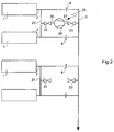
- Fig. 2 shows electrolysis cells 1 that are connected by a suction duct 2 for each cell to a central manifold 3 with a gas treatment centre (not shown) and a central fan (not shown), and in each suction duct 2 a flow restriction device is present. This is the same as in Fig. 1 .
- two suction ducts are connected by a connecting duct 21 having an on/off valve 22.
- the central manifold 3 has also been provided with an on/off valve 23 between the suction ducts.
- the additional ductwork now has a branch 26 for connection to the on/off valve 22, and a duct 27 for connection to the on/off valve 23.
- a booster fan 28 is present for removing gasses from the suction ducts 1 into the central manifold 3.
- the branch 26 and duct 27 can be disconnected from the on/off valves 22 and 23, and thus the additional ductwork 25 can be used for other electrolysis cells.
- the additional ductwork is preferably movable along the central manifold 3, for instance along a rail track (not shown). In this way, using a lighter booster fan and a minimum of additional ducts, all electrolysis cells can be treated and additional gasses released can be removed.
- Fig. 3 again shows electrolysis cells 1 that are connected by a suction duct 2 for each cell to a central manifold 3 with a gas treatment centre (not shown) and a central fan (not shown), and in each suction duct 2 a flow restriction device is present. This is the same as in Fig.1 .
- an additional ductwork 30 which has a branch 31 for removing gasses from above an electrolysis cell, using a booster fan 32 and a duct 33 that is connected to an on/off valve 34 provided at the central manifold 3.
- the additional ductwork is movable along the electrolysis cells and can be used for all electrolysis cells connected to the central manifold, since duct 33 can be disconnected from the on/off valve 34 and connected to another on/off valve provided to the central manifold 3.
- the harmful gasses contain fluorides, but also other polluting elements such as PAH's, SO2, SO3 and dust. PAH's and dust are also removed in the gas treatment centres (PAH is abbreviation of Polycyclic Aromatic Hydrocarbon).
- each electrolysis cell a ductwork is provided, and an embodiment in which each ductwork has three or more branches for three or more electrolysis cells. It will also be understood that the number of ductworks connected to the booster duct can be varied.
- apparatus and method according to the invention can also be used for other electrolysis process besides aluminium electrolysis.
Landscapes
- Chemical & Material Sciences (AREA)
- Engineering & Computer Science (AREA)
- Chemical Kinetics & Catalysis (AREA)
- Electrochemistry (AREA)
- Materials Engineering (AREA)
- Metallurgy (AREA)
- Organic Chemistry (AREA)
- Electrolytic Production Of Metals (AREA)
- Electrolytic Production Of Non-Metals, Compounds, Apparatuses Therefor (AREA)
- Treating Waste Gases (AREA)
Claims (16)
- Vorrichtung zur Entfernung von Gasen von einer Anzahl von Elektrolysezellen (1), aufweisend:eine Absaugleitung (2) für jede Zelle, wobei jede Absaugleitung mit einer zentralen Sammelleitung (3) mit einem Gasbehandlungszentrum (4) und einem zentralen Sauglüfter (5) verbunden ist, dadurch gekennzeichnet dass eine Flussbeschränkungsvorrichtung (6) in jeder Absaugleitung bereitgestellt wird, und wobeieine oder mehrere zusätzliche Leitungen (10) bereitgestellt werden, jede zusätzliche Leitung für eine oder mehrere Absaugleitungen, wobei jede zusätzliche Leitung eine Verzweigung (12) für jede Absaugleitung aufweist, wobei die Verzweigung, zwischen der Elektrolysezelle und der Flussbeschränkungsvorrichtung, mit der Absaugleitung verbunden ist, wobei eine oder mehrere Verzweigungen mit einer Verstärkerleitung (11), in welcher sich ein an/aus Ventil (13) befindet, verbunden sind, wobei eine oder mehrere Verstärkerleitungen mit einer Verstärkersammelleitung verbunden sind, welche mit der zentralen Sammelleitung verbunden ist, wobei ein Verstärkerlüfter in der Verstärkersammelleitung breitgestellt ist.
- Vorrichtung gemäß Anspruch 1, wobei
jede zusätzliche Leitung (10) mit zwei oder mehr Absaugleitungen (2) bereitgestellt ist, vorzugsweise ist jede zusätzliche Leitung mit zwei Absaugleitungen bereitgestellt. - Vorrichtung gemäß einem der Ansprüche 1 oder 2, wobei
mindestens eine der Absaugleitungen (2), welche mit zusätzlichen Leitungen breitgestellt werden, frei von Ventilen, wie beispielsweise an/aus Ventilen (13) ist, vorzugsweise ist mindestens die Hälfte der Absaugleitungen frei von Ventilen, und noch bevorzugter sind alle Absaugleitungen frei von Ventilen. - Vorrichtung gemäß einem der Ansprüche 1 - 3, wobei
die an/aus Ventile (13) in den Verstärkerleitungen (11) automatische Ventile sind, welche durch eine zentrale Steuereinheit gesteuert werden. - Vorrichtung gemäß einem der Ansprüche 1 - 4, wobei
die Verstärkerleitungen (11) für acht bis zwanzig Elektrolysezellen (1) mit einer Verstärkersammelleitung verbunden sind. - Vorrichtung gemäß Anspruch 5, wobei
jede Verstärkerleitung (11) mit zwei Absaugleitungen (2) verbunden ist, und sieben Verstärkerleitungen mit einer Verstärkersammelleitung (14) verbunden sind. - Vorrichtung gemäß einem der vorhergehenden Ansprüche, wobei
der zentrale Absauglüfter (5) ein Saugvolumen von 2000 bis 10000 N m3/h für jede Elektrolysezelle (1) im Betrieb bereitstellt, vorzugsweise ein Saugvolumen von 4000 bis 6000 N m3/h für jede Elektrolysezelle im Betrieb. - Vorrichtung gemäß Anspruch 7, wobei
der Verstärkerlüfter (15) ein Saugvolumen für zwei Absaugleitungen (2) bereitstellt, das zwei bis viermal so viel ist wie das Saugvolumen, welches durch den zentralen Absauglüfter (5) für jede Elektrolysezelle (1) im Betrieb bereitgestellt wird. - Vorrichtung gemäß einem der vorhergehenden Ansprüche, wobei
die Elektrolysezellen (1) Aluminium-Elektrolysezellen sind. - Vorrichtung zur Entfernung von Gasen von einer Anzahl von Elektrolysezellen (1), aufweisend:eine Absaugleitung (2) für jede Zelle, wobei jede Absaugleitung mit einer zentralen Sammelleitung (3) mit einem Gasbehandlungszentrum (4) und einem zentralen Sauglüfter (5) verbunden ist, dadurch gekennzeichnet dass eine Flussbeschränkungsvorrichtung (6) in jeder Absaugleitung bereitgestellt ist, wobeieine zusätzliche Leitung (10) bereitgestellt ist, welche lösbar mit der Vorrichtung verbunden ist, wobeidie zusätzliche Leitung eine zusätzliche Verstärkerleitung aufweist und eine oder mehrere Verzweigungen (26), welche lösbar mit den entsprechenden Absaugleitungen der Vorrichtung, zwischen der Elektrolysezelle und der Flussbeschränkungsvorrichtung, verbunden sind, wobei die zusätzliche Verstärkerleitung lösbar mit der zentralen Sammelleitung verbunden ist, und wobeidie zusätzlichen Leitungen einen Verstärkerlüfter (28) aufweisen, für die Entfernung von Gasen von den Elektrolysezellen durch die Absaugleitungen und die Verzweigungen in die zentrale Sammelleitung.
- Vorrichtung gemäß Anspruch 10, wobei
die zusätzlichen Leitungen zwei oder mehr Verzweigungen aufweisen, vorzugsweise zwei Verzweigungen, welche lösbar mit den entsprechenden Absaugleitungen verbunden sind, oder wobei
die zusätzlichen Leitungen eine Verzweigung aufweisen, welche lösbar mit einer Verbindungsleitung (21) zwischen zwei oder mehreren Absaugleitungen (2) verbunden ist. - Vorrichtung gemäß Anspruch 10 oder 11, wobei
die zusätzliche Leitung bewegbar entlang der Elektrolysezellen und verbindbar zu allen Absaugleitungen (2) der Elektrolysezellen (1) ist. - Vorrichtung gemäß einem der Ansprüche 10 - 12, wobei
die Absaugleitungen (2) und die zentrale Sammelleitung (3) mit an/aus Ventilen (23) zur Verbindung mit der zusätzlichen Leitung bereitgestellt sind. - Verfahren zum Durchführen eines Elektrolyseprozesses, dadurch
gekennzeichnet dass
Gase, welche während des Elektrolyseprozesses gebildet werden, durch Verwenden einer Vorrichtung gemäß einem der vorhergehenden Ansprüche entfernt werden. - Verfahren gemäß Anspruch 14, wobei
die Gase, die gebildet wurden, Gase sind, welche Fluoride enthalten, die während eines Aluminiumelektrolyse Prozesses unter Verwendung des Hall-Heroult Prozess gebildet wurden. - Verfahren gemäß Anspruch 14 oder 15, wobei
die zusätzlichen Leitungen zum Absaugen verwendet werden, wenn eine oder mehrere der Elektrolysezellen geöffnet sind.
Priority Applications (1)
| Application Number | Priority Date | Filing Date | Title |
|---|---|---|---|
| EP07846831.1A EP2108059B8 (de) | 2006-12-21 | 2007-11-27 | Vorrichtung und verfahren zur entfernung von gasen |
Applications Claiming Priority (4)
| Application Number | Priority Date | Filing Date | Title |
|---|---|---|---|
| EP06026549A EP1936011A1 (de) | 2006-12-21 | 2006-12-21 | Vorrichtung und Verfahren zur Gasentfernung |
| EP07005634 | 2007-03-20 | ||
| EP07846831.1A EP2108059B8 (de) | 2006-12-21 | 2007-11-27 | Vorrichtung und verfahren zur entfernung von gasen |
| PCT/EP2007/010266 WO2008074386A2 (en) | 2006-12-21 | 2007-11-27 | Apparatus and method for th removal of gasses |
Publications (3)
| Publication Number | Publication Date |
|---|---|
| EP2108059A2 EP2108059A2 (de) | 2009-10-14 |
| EP2108059B1 true EP2108059B1 (de) | 2016-01-27 |
| EP2108059B8 EP2108059B8 (de) | 2016-03-16 |
Family
ID=39466096
Family Applications (1)
| Application Number | Title | Priority Date | Filing Date |
|---|---|---|---|
| EP07846831.1A Not-in-force EP2108059B8 (de) | 2006-12-21 | 2007-11-27 | Vorrichtung und verfahren zur entfernung von gasen |
Country Status (10)
| Country | Link |
|---|---|
| US (1) | US8449738B2 (de) |
| EP (1) | EP2108059B8 (de) |
| CN (1) | CN101589180B (de) |
| AU (1) | AU2007334985B2 (de) |
| BR (1) | BRPI0720698A2 (de) |
| CA (1) | CA2673431C (de) |
| ES (1) | ES2564171T3 (de) |
| NO (1) | NO20092728L (de) |
| RU (1) | RU2450090C2 (de) |
| WO (1) | WO2008074386A2 (de) |
Families Citing this family (7)
| Publication number | Priority date | Publication date | Assignee | Title |
|---|---|---|---|---|
| EP2248605A1 (de) * | 2009-05-06 | 2010-11-10 | Danieli Corus BV | Verfahren und Vorrichtung zur Ausgleichsentfernung von Gasen aus Elektrolysezellen durch Absaugung |
| FR2948128B1 (fr) * | 2009-07-20 | 2011-12-23 | Solios Environnement | Dispositif de collecte des gaz emis par des cuves d'electrolyse d'aluminium, et systeme de production d'aluminium associe |
| FR2963625B1 (fr) | 2010-08-06 | 2013-02-22 | Solios Environnement | Installation pour la collecte des gaz d'une pluralite de cuves d'electrolyse et dispositif d'ajustement pour une telle installation |
| FR2963793B1 (fr) | 2010-08-10 | 2012-09-07 | Solios Environnement | Procede et dispositif de confinement des gaz de cuve dans une cuve d'electrolyse de l'aluminium |
| US9234286B2 (en) | 2012-05-04 | 2016-01-12 | Alstom Technology Ltd | Recycled pot gas pot distribution |
| FR3016901B1 (fr) * | 2014-01-27 | 2016-01-15 | Rio Tinto Alcan Int Ltd | Cuve d'electrolyse pour la production d'aluminium comprenant un dispositif de collecte de gaz. |
| NO20181482A1 (en) * | 2018-11-20 | 2020-05-21 | Norsk Hydro As | Method and system for controlling suction of off-gases from electrolysis cells |
Family Cites Families (6)
| Publication number | Priority date | Publication date | Assignee | Title |
|---|---|---|---|---|
| CA1197074A (en) * | 1981-12-04 | 1985-11-26 | Isaias Loukos | Method and apparatus for cleaning waste gases from aluminum production facilities |
| FR2563845B1 (fr) * | 1984-05-03 | 1986-10-03 | Pechiney Aluminium | Procede et dispositif de suraspiration automatique sur les cuves d'electrolyse pour la production d'aluminium |
| CN1223696A (zh) * | 1997-04-30 | 1999-07-21 | 株式会社住友斯蒂克斯尼崎 | 金属镁电解装置 |
| DE19845258C1 (de) * | 1998-10-01 | 2000-03-16 | Hamburger Aluminium Werk Gmbh | Anlage zum Absaugen der Abgase und zur Nutzung ihrer Abwärme für eine Anlage zur Aluminiumschmelzflußelektrolyse mit mehreren Elektrolysezellen |
| NO315278B1 (no) * | 2001-11-14 | 2003-08-11 | Norsk Hydro As | Fremgangsmåte for drift av et pre-bake elektrolysecelleanlegg, samt arrangement for benyttelse i samme |
| RU2218453C1 (ru) * | 2002-05-06 | 2003-12-10 | Открытое акционерное общество "Всероссийский алюминиево-магниевый институт" | Устройство для сбора и удаления газов алюминиевого электролизера |
-
2007
- 2007-11-27 US US12/519,411 patent/US8449738B2/en not_active Expired - Fee Related
- 2007-11-27 BR BRPI0720698-4A2A patent/BRPI0720698A2/pt not_active IP Right Cessation
- 2007-11-27 AU AU2007334985A patent/AU2007334985B2/en not_active Ceased
- 2007-11-27 CN CN200780049896.0A patent/CN101589180B/zh not_active Expired - Fee Related
- 2007-11-27 ES ES07846831.1T patent/ES2564171T3/es active Active
- 2007-11-27 EP EP07846831.1A patent/EP2108059B8/de not_active Not-in-force
- 2007-11-27 WO PCT/EP2007/010266 patent/WO2008074386A2/en not_active Ceased
- 2007-11-27 RU RU2009128041/02A patent/RU2450090C2/ru not_active IP Right Cessation
- 2007-11-27 CA CA2673431A patent/CA2673431C/en not_active Expired - Fee Related
-
2009
- 2009-07-20 NO NO20092728A patent/NO20092728L/no not_active Application Discontinuation
Also Published As
| Publication number | Publication date |
|---|---|
| BRPI0720698A2 (pt) | 2014-02-18 |
| WO2008074386A3 (en) | 2009-01-15 |
| AU2007334985A1 (en) | 2008-06-26 |
| EP2108059A2 (de) | 2009-10-14 |
| ES2564171T3 (es) | 2016-03-18 |
| AU2007334985B2 (en) | 2012-05-17 |
| US20100044217A1 (en) | 2010-02-25 |
| CN101589180A (zh) | 2009-11-25 |
| WO2008074386A2 (en) | 2008-06-26 |
| US8449738B2 (en) | 2013-05-28 |
| CA2673431C (en) | 2012-07-03 |
| EP2108059B8 (de) | 2016-03-16 |
| CN101589180B (zh) | 2011-04-06 |
| RU2009128041A (ru) | 2011-01-27 |
| RU2450090C2 (ru) | 2012-05-10 |
| CA2673431A1 (en) | 2008-06-26 |
| NO20092728L (no) | 2009-07-20 |
Similar Documents
| Publication | Publication Date | Title |
|---|---|---|
| EP2108059B1 (de) | Vorrichtung und verfahren zur entfernung von gasen | |
| RU2436872C2 (ru) | Система и способ улавливания выбросов из электролизера | |
| SA07280647B1 (ar) | عملية ونظام لتنقية الدخان الصادر من فرن تحميص أنودي في التحليل الكهربائي للألومنيوم | |
| EP2067941A2 (de) | Kombikraftwerk mit Abgasrückführung und CO2-Abscheidung sowie Verfahren zum Betrieb eines solchen Kombikraftwerks | |
| CA2451861C (en) | A process and a device for transport of gas | |
| CN115288769A (zh) | 一种人防工程进风系统的控制方法 | |
| EP1936011A1 (de) | Vorrichtung und Verfahren zur Gasentfernung | |
| CN101816867B (zh) | 袋式除尘器中脉冲喷吹控制方法 | |
| CN102872691A (zh) | 油漆废气处理工艺 | |
| CN102181309A (zh) | 焦炉煤气脱硫塔多级运行方法 | |
| EP2248605A1 (de) | Verfahren und Vorrichtung zur Ausgleichsentfernung von Gasen aus Elektrolysezellen durch Absaugung | |
| CA2585225A1 (en) | Apparatus for collection and removal of gases from an aluminum reduction cell | |
| CN111575436B (zh) | 除尘方法 | |
| WO2021173026A1 (ru) | Система для удаления газов из алюминиевого электролизера | |
| CN203810948U (zh) | 烧结废气减排处理系统 | |
| CN110388651A (zh) | 锅炉排烟过桥式旁路精滤装置 | |
| CN104906881A (zh) | 一种防止废气溢出和检修安全的废气除尘装置 | |
| GB2068517A (en) | Preventing smoke generation in coke ovens | |
| EP3730894A3 (de) | Wählspur mit unterschiedlichen höhen und entfernbarem wählhebelanschlag | |
| CN218403960U (zh) | 一种玻璃熔窑气流处理系统 | |
| CN2757946Y (zh) | 具有在线大修改造功能的除尘装置 | |
| CN216378044U (zh) | 一种焦炉烟气循环支管砣阀 | |
| CN211799392U (zh) | 防止主烟管端头槽抽风不足的电解槽烟气净化设备 | |
| Sørhuus et al. | Update on the Abart Gas Treatment Center Technology | |
| CN115250806A (zh) | 一种焦炉焦侧无骨架大棚新风置换装置 |
Legal Events
| Date | Code | Title | Description |
|---|---|---|---|
| PUAI | Public reference made under article 153(3) epc to a published international application that has entered the european phase |
Free format text: ORIGINAL CODE: 0009012 |
|
| 17P | Request for examination filed |
Effective date: 20090721 |
|
| AK | Designated contracting states |
Kind code of ref document: A2 Designated state(s): AT BE BG CH CY CZ DE DK EE ES FI FR GB GR HU IE IS IT LI LT LU LV MC MT NL PL PT RO SE SI SK TR |
|
| DAX | Request for extension of the european patent (deleted) | ||
| 17Q | First examination report despatched |
Effective date: 20120731 |
|
| GRAP | Despatch of communication of intention to grant a patent |
Free format text: ORIGINAL CODE: EPIDOSNIGR1 |
|
| INTG | Intention to grant announced |
Effective date: 20150730 |
|
| GRAS | Grant fee paid |
Free format text: ORIGINAL CODE: EPIDOSNIGR3 |
|
| GRAA | (expected) grant |
Free format text: ORIGINAL CODE: 0009210 |
|
| AK | Designated contracting states |
Kind code of ref document: B1 Designated state(s): AT BE BG CH CY CZ DE DK EE ES FI FR GB GR HU IE IS IT LI LT LU LV MC MT NL PL PT RO SE SI SK TR |
|
| REG | Reference to a national code |
Ref country code: GB Ref legal event code: FG4D |
|
| REG | Reference to a national code |
Ref country code: CH Ref legal event code: EP |
|
| GRAT | Correction requested after decision to grant or after decision to maintain patent in amended form |
Free format text: ORIGINAL CODE: EPIDOSNCDEC |
|
| REG | Reference to a national code |
Ref country code: AT Ref legal event code: REF Ref document number: 772769 Country of ref document: AT Kind code of ref document: T Effective date: 20160215 |
|
| REG | Reference to a national code |
Ref country code: SE Ref legal event code: TRGR |
|
| REG | Reference to a national code |
Ref country code: IE Ref legal event code: FG4D |
|
| REG | Reference to a national code |
Ref country code: DE Ref legal event code: R096 Ref document number: 602007044721 Country of ref document: DE |
|
| REG | Reference to a national code |
Ref country code: ES Ref legal event code: FG2A Ref document number: 2564171 Country of ref document: ES Kind code of ref document: T3 Effective date: 20160318 |
|
| REG | Reference to a national code |
Ref country code: RO Ref legal event code: EPE |
|
| REG | Reference to a national code |
Ref country code: NL Ref legal event code: FP |
|
| REG | Reference to a national code |
Ref country code: LT Ref legal event code: MG4D |
|
| REG | Reference to a national code |
Ref country code: AT Ref legal event code: MK05 Ref document number: 772769 Country of ref document: AT Kind code of ref document: T Effective date: 20160127 |
|
| REG | Reference to a national code |
Ref country code: GR Ref legal event code: EP Ref document number: 20160400583 Country of ref document: GR Effective date: 20160505 |
|
| PG25 | Lapsed in a contracting state [announced via postgrant information from national office to epo] |
Ref country code: FI Free format text: LAPSE BECAUSE OF FAILURE TO SUBMIT A TRANSLATION OF THE DESCRIPTION OR TO PAY THE FEE WITHIN THE PRESCRIBED TIME-LIMIT Effective date: 20160127 Ref country code: IT Free format text: LAPSE BECAUSE OF FAILURE TO SUBMIT A TRANSLATION OF THE DESCRIPTION OR TO PAY THE FEE WITHIN THE PRESCRIBED TIME-LIMIT Effective date: 20160127 |
|
| PG25 | Lapsed in a contracting state [announced via postgrant information from national office to epo] |
Ref country code: PL Free format text: LAPSE BECAUSE OF FAILURE TO SUBMIT A TRANSLATION OF THE DESCRIPTION OR TO PAY THE FEE WITHIN THE PRESCRIBED TIME-LIMIT Effective date: 20160127 Ref country code: PT Free format text: LAPSE BECAUSE OF FAILURE TO SUBMIT A TRANSLATION OF THE DESCRIPTION OR TO PAY THE FEE WITHIN THE PRESCRIBED TIME-LIMIT Effective date: 20160527 Ref country code: LT Free format text: LAPSE BECAUSE OF FAILURE TO SUBMIT A TRANSLATION OF THE DESCRIPTION OR TO PAY THE FEE WITHIN THE PRESCRIBED TIME-LIMIT Effective date: 20160127 Ref country code: AT Free format text: LAPSE BECAUSE OF FAILURE TO SUBMIT A TRANSLATION OF THE DESCRIPTION OR TO PAY THE FEE WITHIN THE PRESCRIBED TIME-LIMIT Effective date: 20160127 Ref country code: LV Free format text: LAPSE BECAUSE OF FAILURE TO SUBMIT A TRANSLATION OF THE DESCRIPTION OR TO PAY THE FEE WITHIN THE PRESCRIBED TIME-LIMIT Effective date: 20160127 |
|
| REG | Reference to a national code |
Ref country code: DE Ref legal event code: R097 Ref document number: 602007044721 Country of ref document: DE |
|
| PG25 | Lapsed in a contracting state [announced via postgrant information from national office to epo] |
Ref country code: DK Free format text: LAPSE BECAUSE OF FAILURE TO SUBMIT A TRANSLATION OF THE DESCRIPTION OR TO PAY THE FEE WITHIN THE PRESCRIBED TIME-LIMIT Effective date: 20160127 Ref country code: EE Free format text: LAPSE BECAUSE OF FAILURE TO SUBMIT A TRANSLATION OF THE DESCRIPTION OR TO PAY THE FEE WITHIN THE PRESCRIBED TIME-LIMIT Effective date: 20160127 |
|
| REG | Reference to a national code |
Ref country code: FR Ref legal event code: PLFP Year of fee payment: 10 |
|
| PG25 | Lapsed in a contracting state [announced via postgrant information from national office to epo] |
Ref country code: CZ Free format text: LAPSE BECAUSE OF FAILURE TO SUBMIT A TRANSLATION OF THE DESCRIPTION OR TO PAY THE FEE WITHIN THE PRESCRIBED TIME-LIMIT Effective date: 20160127 Ref country code: SK Free format text: LAPSE BECAUSE OF FAILURE TO SUBMIT A TRANSLATION OF THE DESCRIPTION OR TO PAY THE FEE WITHIN THE PRESCRIBED TIME-LIMIT Effective date: 20160127 |
|
| PLBE | No opposition filed within time limit |
Free format text: ORIGINAL CODE: 0009261 |
|
| STAA | Information on the status of an ep patent application or granted ep patent |
Free format text: STATUS: NO OPPOSITION FILED WITHIN TIME LIMIT |
|
| PG25 | Lapsed in a contracting state [announced via postgrant information from national office to epo] |
Ref country code: BE Free format text: LAPSE BECAUSE OF FAILURE TO SUBMIT A TRANSLATION OF THE DESCRIPTION OR TO PAY THE FEE WITHIN THE PRESCRIBED TIME-LIMIT Effective date: 20160127 |
|
| 26N | No opposition filed |
Effective date: 20161028 |
|
| PGFP | Annual fee paid to national office [announced via postgrant information from national office to epo] |
Ref country code: NL Payment date: 20161130 Year of fee payment: 10 Ref country code: FR Payment date: 20161123 Year of fee payment: 10 Ref country code: IS Payment date: 20161101 Year of fee payment: 10 |
|
| PG25 | Lapsed in a contracting state [announced via postgrant information from national office to epo] |
Ref country code: BG Free format text: LAPSE BECAUSE OF FAILURE TO SUBMIT A TRANSLATION OF THE DESCRIPTION OR TO PAY THE FEE WITHIN THE PRESCRIBED TIME-LIMIT Effective date: 20160427 Ref country code: SI Free format text: LAPSE BECAUSE OF FAILURE TO SUBMIT A TRANSLATION OF THE DESCRIPTION OR TO PAY THE FEE WITHIN THE PRESCRIBED TIME-LIMIT Effective date: 20160127 |
|
| PGFP | Annual fee paid to national office [announced via postgrant information from national office to epo] |
Ref country code: RO Payment date: 20161107 Year of fee payment: 10 Ref country code: SE Payment date: 20161125 Year of fee payment: 10 Ref country code: GR Payment date: 20161128 Year of fee payment: 10 Ref country code: ES Payment date: 20161128 Year of fee payment: 10 |
|
| PGFP | Annual fee paid to national office [announced via postgrant information from national office to epo] |
Ref country code: TR Payment date: 20161108 Year of fee payment: 10 Ref country code: DE Payment date: 20170125 Year of fee payment: 10 |
|
| REG | Reference to a national code |
Ref country code: CH Ref legal event code: PL |
|
| GBPC | Gb: european patent ceased through non-payment of renewal fee |
Effective date: 20161127 |
|
| PG25 | Lapsed in a contracting state [announced via postgrant information from national office to epo] |
Ref country code: LI Free format text: LAPSE BECAUSE OF NON-PAYMENT OF DUE FEES Effective date: 20161130 Ref country code: CH Free format text: LAPSE BECAUSE OF NON-PAYMENT OF DUE FEES Effective date: 20161130 |
|
| REG | Reference to a national code |
Ref country code: IE Ref legal event code: MM4A |
|
| PG25 | Lapsed in a contracting state [announced via postgrant information from national office to epo] |
Ref country code: LU Free format text: LAPSE BECAUSE OF NON-PAYMENT OF DUE FEES Effective date: 20161130 |
|
| PG25 | Lapsed in a contracting state [announced via postgrant information from national office to epo] |
Ref country code: IE Free format text: LAPSE BECAUSE OF NON-PAYMENT OF DUE FEES Effective date: 20161127 Ref country code: GB Free format text: LAPSE BECAUSE OF NON-PAYMENT OF DUE FEES Effective date: 20161127 |
|
| PG25 | Lapsed in a contracting state [announced via postgrant information from national office to epo] |
Ref country code: HU Free format text: LAPSE BECAUSE OF FAILURE TO SUBMIT A TRANSLATION OF THE DESCRIPTION OR TO PAY THE FEE WITHIN THE PRESCRIBED TIME-LIMIT; INVALID AB INITIO Effective date: 20071127 Ref country code: CY Free format text: LAPSE BECAUSE OF FAILURE TO SUBMIT A TRANSLATION OF THE DESCRIPTION OR TO PAY THE FEE WITHIN THE PRESCRIBED TIME-LIMIT Effective date: 20160127 |
|
| REG | Reference to a national code |
Ref country code: DE Ref legal event code: R119 Ref document number: 602007044721 Country of ref document: DE |
|
| PG25 | Lapsed in a contracting state [announced via postgrant information from national office to epo] |
Ref country code: MC Free format text: LAPSE BECAUSE OF FAILURE TO SUBMIT A TRANSLATION OF THE DESCRIPTION OR TO PAY THE FEE WITHIN THE PRESCRIBED TIME-LIMIT Effective date: 20160127 |
|
| REG | Reference to a national code |
Ref country code: SE Ref legal event code: EUG |
|
| REG | Reference to a national code |
Ref country code: NL Ref legal event code: MM Effective date: 20171201 |
|
| PG25 | Lapsed in a contracting state [announced via postgrant information from national office to epo] |
Ref country code: GR Free format text: LAPSE BECAUSE OF NON-PAYMENT OF DUE FEES Effective date: 20180604 Ref country code: IS Free format text: LAPSE BECAUSE OF FAILURE TO SUBMIT A TRANSLATION OF THE DESCRIPTION OR TO PAY THE FEE WITHIN THE PRESCRIBED TIME-LIMIT Effective date: 20180531 Ref country code: SE Free format text: LAPSE BECAUSE OF NON-PAYMENT OF DUE FEES Effective date: 20171128 Ref country code: RO Free format text: LAPSE BECAUSE OF NON-PAYMENT OF DUE FEES Effective date: 20171127 |
|
| REG | Reference to a national code |
Ref country code: FR Ref legal event code: ST Effective date: 20180731 |
|
| PG25 | Lapsed in a contracting state [announced via postgrant information from national office to epo] |
Ref country code: MT Free format text: LAPSE BECAUSE OF NON-PAYMENT OF DUE FEES Effective date: 20161127 |
|
| PG25 | Lapsed in a contracting state [announced via postgrant information from national office to epo] |
Ref country code: NL Free format text: LAPSE BECAUSE OF NON-PAYMENT OF DUE FEES Effective date: 20171201 Ref country code: FR Free format text: LAPSE BECAUSE OF NON-PAYMENT OF DUE FEES Effective date: 20171130 Ref country code: DE Free format text: LAPSE BECAUSE OF NON-PAYMENT OF DUE FEES Effective date: 20180602 |
|
| PG25 | Lapsed in a contracting state [announced via postgrant information from national office to epo] |
Ref country code: ES Free format text: LAPSE BECAUSE OF NON-PAYMENT OF DUE FEES Effective date: 20171128 |
|
| PG25 | Lapsed in a contracting state [announced via postgrant information from national office to epo] |
Ref country code: TR Free format text: LAPSE BECAUSE OF NON-PAYMENT OF DUE FEES Effective date: 20171127 |