EP2107765A1 - Appareil de station pour une installation de communication domestique - Google Patents
Appareil de station pour une installation de communication domestique Download PDFInfo
- Publication number
- EP2107765A1 EP2107765A1 EP08153898A EP08153898A EP2107765A1 EP 2107765 A1 EP2107765 A1 EP 2107765A1 EP 08153898 A EP08153898 A EP 08153898A EP 08153898 A EP08153898 A EP 08153898A EP 2107765 A1 EP2107765 A1 EP 2107765A1
- Authority
- EP
- European Patent Office
- Prior art keywords
- station device
- housing
- sound
- microphone
- circuit board
- Prior art date
- Legal status (The legal status is an assumption and is not a legal conclusion. Google has not performed a legal analysis and makes no representation as to the accuracy of the status listed.)
- Withdrawn
Links
Images


Classifications
-
- H—ELECTRICITY
- H04—ELECTRIC COMMUNICATION TECHNIQUE
- H04M—TELEPHONIC COMMUNICATION
- H04M11/00—Telephonic communication systems specially adapted for combination with other electrical systems
- H04M11/02—Telephonic communication systems specially adapted for combination with other electrical systems with bell or annunciator systems
- H04M11/025—Door telephones
-
- H—ELECTRICITY
- H04—ELECTRIC COMMUNICATION TECHNIQUE
- H04M—TELEPHONIC COMMUNICATION
- H04M1/00—Substation equipment, e.g. for use by subscribers
- H04M1/02—Constructional features of telephone sets
- H04M1/0291—Door telephones
-
- H—ELECTRICITY
- H04—ELECTRIC COMMUNICATION TECHNIQUE
- H04M—TELEPHONIC COMMUNICATION
- H04M1/00—Substation equipment, e.g. for use by subscribers
- H04M1/02—Constructional features of telephone sets
- H04M1/03—Constructional features of telephone transmitters or receivers, e.g. telephone hand-sets
- H04M1/035—Improving the acoustic characteristics by means of constructional features of the housing, e.g. ribs, walls, resonating chambers or cavities
-
- H—ELECTRICITY
- H01—ELECTRIC ELEMENTS
- H01R—ELECTRICALLY-CONDUCTIVE CONNECTIONS; STRUCTURAL ASSOCIATIONS OF A PLURALITY OF MUTUALLY-INSULATED ELECTRICAL CONNECTING ELEMENTS; COUPLING DEVICES; CURRENT COLLECTORS
- H01R12/00—Structural associations of a plurality of mutually-insulated electrical connecting elements, specially adapted for printed circuits, e.g. printed circuit boards [PCB], flat or ribbon cables, or like generally planar structures, e.g. terminal strips, terminal blocks; Coupling devices specially adapted for printed circuits, flat or ribbon cables, or like generally planar structures; Terminals specially adapted for contact with, or insertion into, printed circuits, flat or ribbon cables, or like generally planar structures
- H01R12/70—Coupling devices
- H01R12/71—Coupling devices for rigid printing circuits or like structures
- H01R12/712—Coupling devices for rigid printing circuits or like structures co-operating with the surface of the printed circuit or with a coupling device exclusively provided on the surface of the printed circuit
- H01R12/714—Coupling devices for rigid printing circuits or like structures co-operating with the surface of the printed circuit or with a coupling device exclusively provided on the surface of the printed circuit with contacts abutting directly the printed circuit; Button contacts therefore provided on the printed circuit
Definitions
- the present invention relates to a station device, in particular a home station, for a home communication system, with a device housing, with audio components with a microphone and a speaker for audio communication after establishing a communication connection with another station device of the home communication system and preferably with Video components with a display for displaying a video image.
- the EP 1 843 590 A1 describes a home communication system with at least one station device of the type described. Specifically, it is a video home station.
- a connected to the home station via a two-wire bus or connectable to a call signal, arranged outside a house front door door station has a video camera, the display of the home station for displaying a video image of the video camera of the door station based on a to be transmitted via the bus video signal is provided.
- the electrical components, such as microphone and speakers are connected via electrical connection lines to an internal circuit, wherein the cables must be soldered during the assembly of equipment or connected via connectors, resulting in a correspondingly high cost in the production of the device.
- the known video-station device compared to a pure audio station, which has no video display, but only audio components (especially for a speakerphone microphone and speakers), designed very large, because a housing front panel a first surface area for the speaker and associated sound openings and offset to a second surface area with the video display has.
- the present invention is based on the object to provide a station device of the type described above, which can be produced in a simple and economical manner and in particular also has a particularly compact design.
- the microphone is connected via electrical connections to a printed circuit board, wherein the terminals are formed by resilient abutment contact elements, which rest electrically conductive on contact surfaces of the circuit board.
- the contact surfaces of the printed circuit board from an inner, in particular circular contact surface and this preferably annular and concentrically enclosing outer contact surface.
- the terminals of the microphone are designed as contact elements such that they discretely, regardless of the Drehrecardi of the microphone, the contact surfaces, d. H. separate from each other, contact. From this advantageous embodiment, a particularly simple assembly results in the production of the station device according to the invention.
- the small, capsule-type microphone only needs to be inserted into a receptacle of a carrier part, and the carrier part is then joined to the associated circuit board in a direction perpendicular to the plane of the circuit board.
- the connection contact of the microphone is thus carried out solely by joining the components by the circuit board is mechanically connected to the microphone receiving support member. Due to the preferred embodiment of the contact surfaces and a correspondingly adapted configuration of the contact contact connections of the microphone, the connection is advantageously independent of the rotational orientation of the microphone within the receptacle of the carrier part. This leads to a very simple and quick installation, especially since also unnecessary connection cables for the microphone and line connections.
- the microphone is disposed within the device such that it is acoustically largely decoupled from the sound of the speaker. This will be explained in more detail below.
- the loudspeaker of the audio components is arranged within the housing in a region covered by the display to a front device viewing side, wherein the loudspeaker is assigned a sound chamber with at least one lateral housing sound opening.
- the speaker is housed practically behind the video display, so that in the surface area of a housing front also eliminates an area with sound openings.
- a significant reduction in size is achieved with respect to the area size of the housing front.
- About the loudspeaker within the housing upstream sonic chamber and the lateral, that is arranged in the region of a housing side wall sound opening still good sound guidance is achieved.
- two sound openings are provided in opposite side walls, each sound opening being connected to the sound chamber via an internal sound channel. This embodiment ensures effective conduction of the sound out of the housing to the outside.
- the speaker is assigned on its side remote from the sound chamber side, an acoustic return volume, this back volume to avoid an acoustic short circuit from the sound chamber acoustically isolated (acoustically sealed or isolated / decoupled) ,
- acoustic return volume assigns on its side remote from the sound chamber side, an acoustic return volume, this back volume to avoid an acoustic short circuit from the sound chamber acoustically isolated (acoustically sealed or isolated / decoupled) ,
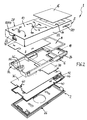
- An inventive station device 1 (see the assembly in Fig. 1 ) is part of a home communication system.
- Such systems are installed in buildings from at least one door station (outside near a front door) and any number of home stations by all stations are preferably connected to each other via a common two-wire bus.
- the bus is designed for the transmission of digital control signals and communication signals, namely audio and video signals, and preferably additionally transmits the supply voltage from a central power supply unit to the individual stations.
- the station device 1 is designed in particular as a home station, which is to be arranged in the interior of an apartment.
- the station device 1 has a device housing 2 and audio components with a microphone 4 (s. Fig. 5 ) and a loudspeaker 6 ( Fig. 2 and 3 ) on.
- the station device 1 preferably also has video components with a display 8 for displaying a video image and / or a user menu.
- 2 control and display elements 12 are provided in the region of a front wall 10 of the device housing.
- the audio components with the microphone 4 and the speaker 6 are provided for audio communication between the stations, in particular between the door station and at least one home station. Preferably, internal connections between at least two home stations are possible.
- a call signal for a certain other station is first generated at a station, in particular the door station, via a call button.
- the system was previously programmed during commissioning with regard to the assignment between call buttons and stations, so that in the stations all call signals transmitted via the bus are monitored.
- the station programmed for the respective call button detects the signal assigned to it and generates an acoustic and / or optical call signal.
- the user can then accept the call by pressing an accept key, thereby establishing an audio connection with the calling party Station is built.
- the video display 8 of the station device 1 is used to display a video image which is generated by a video camera of the door station and transmitted in the form of a preferably outside the audible frequency range modulated video signal via the bus.
- the display 8 is preferably formed by a flat TFT or LCD monitor.
- the display 8 is accommodated directly below the front wall 10 of the device housing 2 in the region of a housing opening 14.
- the housing opening 14 with the display 8 is then preferably covered by an outer transparent cover 16.
- the loudspeaker 6 is arranged within the housing 2 in a region covered by the display 8 for the front device viewing side, ie, "below" the display 8.
- the speaker 6 is a sound chamber 18 (see this particular Fig. 2 and 5 ) associated with at least one lateral housing sound opening 20.
- the housing 2 in the region of two opposite side walls 22 each have one of two sound openings 20, wherein each sound opening 20 is connected to the sound chamber 18 via a sound channel 24.
- the sound chamber 18 and / or the or each sound channel 24 may preferably contain not shown form elements for influencing / guiding the sound.
- the speaker 6 is assigned on its side facing away from the sound chamber 18 side, an acoustic return volume, said back volume to avoid an acoustic short circuit from the sound chamber 18 is acoustically separated. This will be explained in more detail below.
- the device housing 2 is designed for mounting on a wall surface (so-called AP mounting or surface mounting).
- the front housing 28 is formed flat hood-like and consists of the rectangular front wall 10 and four perpendicular side walls 22.
- the base member 26 is as a base plate via suitable fastening means on a Wall surface attachable.
- the front part 28 is then fastened (latched) via latching means 30 on the plate-like base part 26.
- the base member 26 as latching means resilient locking elements which engage in associated latching openings of the front part 28.
- the front part 28 receives a frame-like support member 32.
- the support member 32 also has the sound chamber 18 with lateral sound channels 24, wherein the sound channels 24 merge into each one of the sound openings 20 of the front part 28 of the housing 2, if the carrier part 32 is inserted into the front part 28.
- the sound chamber 18 is best in Fig. 5 to recognize.
- the support part 32 has holding elements 34 for the loudspeaker 6.
- the speaker 6 is mounted on this side of the support member 32, that it is directed with its membrane directly into the sound chamber 18. About the sound channels 24 and the sound holes 20 of the sound from the station device 1 passes to the outside.
- the support member 32 further carries a main circuit board 36 (motherboard with electronic components not shown in detail) and preferably a separate graphics card 38 for the display 8, wherein the display 8 itself is also held by the support member 32.
- the graphics card 38 When mounted, the graphics card 38 is located directly below the display 8 and can be contacted directly via contact pads.
- the graphics card 38 includes an electronic drive device for the display 8 that is not shown in greater detail.
- a plate-like cover member 40 is arranged as a "board cover".
- This cover part 40 is preferably designed in the region of the loudspeaker 6 to form the acoustic return volume.
- the cover part 40 has a receiving space 42 for the rear area of the loudspeaker 6. This is in particular on Fig. 2 to 4 directed.
- This receiving space 42 is acoustically decoupled from the sound chamber 18.
- the cover member 40 has at least one acoustically effective opening 44 in the area of the loudspeaker receiving space 42, so that the acoustic back volume is formed mainly in the area between the cover part 40 and the base part 26.
- the cover part 40 in the region of the receiving space 42 in such a way that the acoustic back volume is then mainly in the region between the cover 40, the support member 32 and the front part 28, ie, consequently formed in the circuit board receiving area.
- the particular advantage of this embodiment is that the tightness of the back volume is independent of the nature of the base member 26 (base plate) and its holder on a wall.
- the microphone 4 is arranged within the device housing 2 in a receptacle 46 so that it is acoustically largely decoupled from the sound of the speaker 6, and in particular of its rearward sound in the region of the back volume. That only in Fig. 5 shown microphone 4 is formed as a small cylindrical capsule.
- the receptacle 46 is formed, in particular, by an opening of the carrier part 32 designed for receiving and holding the microphone 4.
- the housing front part 28 has an annular collar 48 on the inside of the front wall 10. In the mounted, inserted into the front part 28 and preferably latched state of the support member 32 of the annular collar 28 circumferentially engages sealingly into the microphone 4 holding opening 46 of the support member 32 a.
- the annular collar 48 the receptacle 46 to form a sound chamber 50.
- This sound chamber 50 is in a sound channel 52, which opens via a housing sound opening 54 to the outside.
- the sound channel 52 is preferably formed by an integrally formed wall within the front part 28.
- the sound opening 54 is formed in particular in the side wall 22, which points vertically downwards when mounted as intended. How to get out Fig. 2 and 5 results, the support member 32, starting from the receptacle 46 on a groove-like recess 56 for the sound channel 52 of the front housing part 28 on.
- the microphone 4 is connected via electrical connections 58 to a printed circuit board, in particular to the main circuit board 36, wherein the terminals 58 are formed according to the invention of resilient contact elements, the electrically conductive contact surfaces 60 of the circuit board 36 come to rest.
- the contacting of the microphone 4 is thus carried out solely by joining the components by the circuit board 36 is connected to the microphone 4 receiving support member 32.
- the contact surfaces 60 are formed concentrically with each other. This means that an inner contact surface 60a is approximately circular and an outer contact surface 60b is concentric to annular. This is in particular on Fig. 5 directed.
- the contact pads 58 of the microphone 4 are in this case designed and arranged such that they contact the contact surfaces 60 discretely, ie, one contact contacts the inner contact surface 60a and the other contact the outer contact surface 60b, advantageously independent of the rotational orientation of the microphone 4 within the receptacle 36. This leads to a very simple installation, especially as you do not need connecting cables for the microphone.
- the microphone 4 has an outer encapsulation made of a rubber-elastic material.
- a good support within the receptacle 46 ensures and on the other hand, a good acoustic seal by the annular collar 48 of the housing front part 28 comes close to rest on the rubber-elastic encapsulation of the microphone 4.
- an electrical connection part 62 is supported, preferably via latching means 64.
- the connection part 62 has on the one hand electrical connection terminals 66 for electrical lines, not shown. It may preferably be screw terminals, but alternatively also be plug-in terminals.
- the base part 28 has at least one passage opening 68 for guided from a building wall lines.
- the connector 62 has at least two terminals 66 for the two-wire bus.
- two further connection terminals 66 are provided for a floor call button, not shown, arranged outside an apartment, in particular in front of an apartment entrance door.
- connection terminals 66 are present.
- the connection terminals 66 of the connection part 62 are preferably electrically connected via resilient abutment contact elements 70 to a printed circuit board 72 arranged in the front part 28 of the device housing 2.
- This printed circuit board 72 is preferably a so-called "keyboard";
- This printed circuit board 72 also carries switching elements, in particular capacitive switching elements and lighting elements in the area of the operating and display elements 12.
- the printed circuit board 72 is preferably glued into the front housing part 28. As an alternative to gluing, the printed circuit board 72 can also be pressed mechanically against the front part 28.
- the contact contact elements 70 are designed as telescopically variable-length spring pins, which are aligned substantially perpendicular to the circuit board 72.
- the Contact contact elements 70 components of the connection part 62 are connected to the electronics of the station device 1 in a very simple manner via the connection part 62 in that the components need only be joined together, the connections being made via the contact elements 70 resting on the contact surfaces 74 by spring force ,
- it is advantageous to conduction-free internal connections ie it can be omitted internal connection lines and electrical (plug or solder) connections advantageously.
- the preferred type of connection is also advantageous for one additional reason.
- a release of the front part 28 by the provided on a (lower) side locking means 30 can be solved by a housing opening 76 and unlocked.
- the front part 28 can then be pivoted forwards with this (lower) side until the front part 28 is also released from the locking means 30 in its opposite (upper) region.
- the contact contact elements 70 according to the invention allow this relative pivoting movement during opening and also when closing the housing without problems.
- the housing front wall 10 has translucent luminous symbols 78 in each of its areas covering one of the switching elements.
- the printed circuit board 72 has, in addition to the switching elements, associated illuminants.
- each luminous symbol 78 is assigned to each luminous symbol 78 two adjacent light-emitting diodes (not shown in the drawing), as a result of which improved surface illumination of the luminous symbols 78 is achieved.
- the station device 1 user-activatable or deactivatable means for automatic acceptance of incoming from another station device within the home communication system call by automatically establishing an audio connection in response to the incoming call on.
- this function is not accessible to the user by a corresponding menu item does not appear in a user menu displayed on the display.
- An activation of the function by an installer at the commissioning of the home communication system on customer request. Only after this activation does the option "Automatic call acceptance" appear in the user menu. This feature can then be enabled or disabled by the user in the menu.
- the respective operating state can be optically signaled, for example via the light icon 78 in the form of a crossed-out bell. If this light symbol is lit, call silencing is activated (ringing off) and automatic call acceptance is deactivated. If the light symbol is switched off permanently, both functions are deactivated, ie no automatic call acceptance and normal ringing tone. A flashing of the LED signal indicates that the automatic call acceptance is active.
- the state of the Rufabscnies can be provided to switch by briefly pressing the associated switching element of the flashing state for a certain time, for example, two seconds in another display mode.
- the call cut-off is activated, and if the signal is not lit, the call cut-off is not active. If automatic call acceptance is activated, the audio connection is automatically established after the tone call has ended completely, ie preferably with a delay of about two seconds.
- the automatic call acceptance is preferably limited to internal calls, i. H. on connections between home stations.
- the automatic call acceptance allows in the context of a home communication system a structure of a voice connection without operation at the called station, z. As for offices, nursery (baby monitor function), medical practices and the like.
- an additional power supply of, in particular, 24 volts can optionally be connected to the device 1 via the connection part 62 become. In this case, there is always enough power available regardless of the supply via the two-wire bus.
- the station device 1 can have means for automatic (dynamic) recognition of the connected supplementary supply. If these detection means detect the presence of the additional supply voltage, certain additional functions of the station 1 can be released automatically. This relates in particular to the activation of the display 8, regardless of the operating state of the other stations within the system. If the stations were supplied solely via the bus, the power would be limited so that, for example, not all displays of all stations could be in operation at the same time.
- additional supply also any internal calls and other switching functions (such as control of stairwell light, door opener and the like) can be released and then controlled menu-controlled on the display.
- certain operating states-in addition to the display elements 12- can also be displayed on the display in particular verbally.
- the invention is not limited to the illustrated and described embodiments, but also includes all the same in the context of the invention embodiments.
- the invention is not only suitable for bus systems, but also for other wiring systems, for. B. multi-wire systems, such as so-called 1 + n systems, or Ethernet systems (TCP / IP) or radio systems.
- the invention has hitherto not been limited to the feature combination defined in claim 1, but may also be defined by any other combination of specific features of all individually disclosed individual features. This means that in principle virtually every individual feature of claim 1 can be omitted or replaced by at least one individual feature disclosed elsewhere in the application. In this respect, the claim 1 is to be understood only as a first formulation attempt for an invention.
Priority Applications (3)
| Application Number | Priority Date | Filing Date | Title |
|---|---|---|---|
| EP08153898A EP2107765A1 (fr) | 2008-04-01 | 2008-04-01 | Appareil de station pour une installation de communication domestique |
| RU2009111904/09A RU2009111904A (ru) | 2008-04-01 | 2009-03-31 | Станционное устройство для домашнего переговорного устройства |
| CN 200910130348 CN101552851A (zh) | 2008-04-01 | 2009-04-01 | 房屋通信系统的基站设备 |
Applications Claiming Priority (1)
| Application Number | Priority Date | Filing Date | Title |
|---|---|---|---|
| EP08153898A EP2107765A1 (fr) | 2008-04-01 | 2008-04-01 | Appareil de station pour une installation de communication domestique |
Publications (1)
| Publication Number | Publication Date |
|---|---|
| EP2107765A1 true EP2107765A1 (fr) | 2009-10-07 |
Family
ID=39722651
Family Applications (1)
| Application Number | Title | Priority Date | Filing Date |
|---|---|---|---|
| EP08153898A Withdrawn EP2107765A1 (fr) | 2008-04-01 | 2008-04-01 | Appareil de station pour une installation de communication domestique |
Country Status (3)
| Country | Link |
|---|---|
| EP (1) | EP2107765A1 (fr) |
| CN (1) | CN101552851A (fr) |
| RU (1) | RU2009111904A (fr) |
Cited By (1)
| Publication number | Priority date | Publication date | Assignee | Title |
|---|---|---|---|---|
| WO2019179813A1 (fr) * | 2018-03-18 | 2019-09-26 | HiAsset GmbH | Système de montage pour module domotique |
Families Citing this family (3)
| Publication number | Priority date | Publication date | Assignee | Title |
|---|---|---|---|---|
| DE102011017367A1 (de) * | 2011-04-16 | 2012-10-18 | Abb Ag | Haus-Kommunikationssystem mit mindestens einer Türstation und mindestens zwei Wohnungsstationen |
| JP7445478B2 (ja) | 2020-03-19 | 2024-03-07 | アイホン株式会社 | インターホン機器 |
| CN113835476A (zh) * | 2021-09-26 | 2021-12-24 | 维沃移动通信有限公司 | 一种电子设备 |
Citations (8)
| Publication number | Priority date | Publication date | Assignee | Title |
|---|---|---|---|---|
| US5830007A (en) * | 1997-03-04 | 1998-11-03 | Molex Incorporated | Electrical connector for a microphone |
| WO2001006598A1 (fr) * | 1999-07-15 | 2001-01-25 | Avx Corporation | Connecteurs electriques a profil bas pour microphones |
| US20030086562A1 (en) * | 2001-11-08 | 2003-05-08 | Wong John Patrick | Hands-free speaker telephone |
| DE20217877U1 (de) * | 2002-11-18 | 2004-04-01 | Gira Giersiepen Gmbh & Co. Kg | Hauskommunikationssystem mit Zweidraht-Teilnehmeranschluss |
| WO2005088944A1 (fr) * | 2004-03-05 | 2005-09-22 | Motorola Inc. | Port pour dispositif electronique |
| DE102004016539A1 (de) * | 2004-03-31 | 2005-10-20 | Giersiepen Gira Gmbh | Elektro-Installationsgerät zur Wandmontage |
| US20070046837A1 (en) * | 2005-08-29 | 2007-03-01 | David Elberbaum | Method and apparatus for attaching display panels onto wall surface |
| EP1843590A1 (fr) | 2006-04-05 | 2007-10-10 | GIRA Giersiepen GmbH & Co. KG | Installation de communication ménagère tout comme système de vidéo d'appartement |
-
2008
- 2008-04-01 EP EP08153898A patent/EP2107765A1/fr not_active Withdrawn
-
2009
- 2009-03-31 RU RU2009111904/09A patent/RU2009111904A/ru not_active Application Discontinuation
- 2009-04-01 CN CN 200910130348 patent/CN101552851A/zh active Pending
Patent Citations (8)
| Publication number | Priority date | Publication date | Assignee | Title |
|---|---|---|---|---|
| US5830007A (en) * | 1997-03-04 | 1998-11-03 | Molex Incorporated | Electrical connector for a microphone |
| WO2001006598A1 (fr) * | 1999-07-15 | 2001-01-25 | Avx Corporation | Connecteurs electriques a profil bas pour microphones |
| US20030086562A1 (en) * | 2001-11-08 | 2003-05-08 | Wong John Patrick | Hands-free speaker telephone |
| DE20217877U1 (de) * | 2002-11-18 | 2004-04-01 | Gira Giersiepen Gmbh & Co. Kg | Hauskommunikationssystem mit Zweidraht-Teilnehmeranschluss |
| WO2005088944A1 (fr) * | 2004-03-05 | 2005-09-22 | Motorola Inc. | Port pour dispositif electronique |
| DE102004016539A1 (de) * | 2004-03-31 | 2005-10-20 | Giersiepen Gira Gmbh | Elektro-Installationsgerät zur Wandmontage |
| US20070046837A1 (en) * | 2005-08-29 | 2007-03-01 | David Elberbaum | Method and apparatus for attaching display panels onto wall surface |
| EP1843590A1 (fr) | 2006-04-05 | 2007-10-10 | GIRA Giersiepen GmbH & Co. KG | Installation de communication ménagère tout comme système de vidéo d'appartement |
Cited By (1)
| Publication number | Priority date | Publication date | Assignee | Title |
|---|---|---|---|---|
| WO2019179813A1 (fr) * | 2018-03-18 | 2019-09-26 | HiAsset GmbH | Système de montage pour module domotique |
Also Published As
| Publication number | Publication date |
|---|---|
| CN101552851A (zh) | 2009-10-07 |
| RU2009111904A (ru) | 2010-10-10 |
Similar Documents
| Publication | Publication Date | Title |
|---|---|---|
| EP1320244B9 (fr) | Système d'interphone modulaire | |
| DE102005024164B4 (de) | Freisprecheinrichtung für ein Mobiltelefon | |
| DE102007045870B4 (de) | Elektrisches/elektronisches Installationsgerät | |
| EP2107765A1 (fr) | Appareil de station pour une installation de communication domestique | |
| EP2107767B1 (fr) | Appareil de station pour une installation de communication domestique | |
| EP2107778B1 (fr) | Appareil de station pour une installation de communication domestique | |
| EP2107766B1 (fr) | Appareil électrique, en particulier appareil de station pour une installation de communication à domicile | |
| DE202008018434U1 (de) | Stationsgerät für eine Hauskommunikationsanlage | |
| DE102010016180B4 (de) | Türsprechanlage mit Concierge-Funktion | |
| DE102004059224B4 (de) | Türsprechanlage | |
| EP0723254A1 (fr) | Installation d'appel de secours avec échange d'information | |
| DE10139480B4 (de) | Halterung für ein Mobiltelefon im Kraftfahrzeug | |
| EP0054240A2 (fr) | Appareil électrique adapté à l'utilisation en plein air, notamment poste téléphonique pour installation de conversation en alternat, en duplex ou à haut-parleur | |
| EP0191492B1 (fr) | Dispositif de discussion contrôlé par ordinateur | |
| DE102004020311B3 (de) | Wohnungssprechstelle für eine Türsprechanlage | |
| EP1343299A1 (fr) | Appareil téléphonique particulièrement destiné à un montage mural | |
| DE2126180A1 (de) | Gegensprechgerät | |
| DE20221518U1 (de) | Hauskommunikationsanlage | |
| DE19744868A1 (de) | Telefon- und Türsprechanlagen | |
| DE10128323B4 (de) | Halterung für ein Mobiltelefon im Kraftfahrzeug | |
| DE102005062487B3 (de) | Elektrisches / elektronisches Installationsgerät | |
| DE19803009A1 (de) | Fernsteuerung per Telefon | |
| DE104080C (fr) | ||
| EP1451806A2 (fr) | Commande de terminaux | |
| DE19613879A1 (de) | Verbindungskabel zum Anschluß von Komponenten an einen Rundfunkempfänger mit integrierter Fernsprecheinrichtung |
Legal Events
| Date | Code | Title | Description |
|---|---|---|---|
| PUAI | Public reference made under article 153(3) epc to a published international application that has entered the european phase |
Free format text: ORIGINAL CODE: 0009012 |
|
| AK | Designated contracting states |
Kind code of ref document: A1 Designated state(s): AT BE BG CH CY CZ DE DK EE ES FI FR GB GR HR HU IE IS IT LI LT LU LV MC MT NL NO PL PT RO SE SI SK TR |
|
| AX | Request for extension of the european patent |
Extension state: AL BA MK RS |
|
| AKX | Designation fees paid | ||
| STAA | Information on the status of an ep patent application or granted ep patent |
Free format text: STATUS: THE APPLICATION IS DEEMED TO BE WITHDRAWN |
|
| 18D | Application deemed to be withdrawn |
Effective date: 20100408 |
|
| REG | Reference to a national code |
Ref country code: DE Ref legal event code: 8566 |