EP2107327B1 - Thermal gas flow control system in the electric arc furnace - Google Patents
Thermal gas flow control system in the electric arc furnace Download PDFInfo
- Publication number
- EP2107327B1 EP2107327B1 EP20090384801 EP09384801A EP2107327B1 EP 2107327 B1 EP2107327 B1 EP 2107327B1 EP 20090384801 EP20090384801 EP 20090384801 EP 09384801 A EP09384801 A EP 09384801A EP 2107327 B1 EP2107327 B1 EP 2107327B1
- Authority
- EP
- European Patent Office
- Prior art keywords
- scrap
- furnace
- gas
- electric arc
- arc furnace
- Prior art date
- Legal status (The legal status is an assumption and is not a legal conclusion. Google has not performed a legal analysis and makes no representation as to the accuracy of the status listed.)
- Not-in-force
Links
- 238000010891 electric arc Methods 0.000 title claims description 12
- 239000007789 gas Substances 0.000 claims description 56
- 238000000034 method Methods 0.000 claims description 22
- 230000008569 process Effects 0.000 claims description 20
- 239000003517 fume Substances 0.000 claims description 16
- 238000009434 installation Methods 0.000 claims description 14
- 239000002893 slag Substances 0.000 claims description 10
- 230000033228 biological regulation Effects 0.000 claims description 8
- 238000002844 melting Methods 0.000 claims description 2
- 230000008018 melting Effects 0.000 claims description 2
- 238000010626 work up procedure Methods 0.000 claims 1
- 230000009467 reduction Effects 0.000 description 6
- 238000003723 Smelting Methods 0.000 description 5
- 229910052799 carbon Inorganic materials 0.000 description 4
- 238000002347 injection Methods 0.000 description 4
- 239000007924 injection Substances 0.000 description 4
- 239000007787 solid Substances 0.000 description 4
- 238000012546 transfer Methods 0.000 description 4
- OKTJSMMVPCPJKN-UHFFFAOYSA-N Carbon Chemical compound [C] OKTJSMMVPCPJKN-UHFFFAOYSA-N 0.000 description 3
- QVGXLLKOCUKJST-UHFFFAOYSA-N atomic oxygen Chemical compound [O] QVGXLLKOCUKJST-UHFFFAOYSA-N 0.000 description 3
- 238000002485 combustion reaction Methods 0.000 description 3
- 238000011161 development Methods 0.000 description 3
- 230000018109 developmental process Effects 0.000 description 3
- 239000001301 oxygen Substances 0.000 description 3
- 229910052760 oxygen Inorganic materials 0.000 description 3
- 238000010079 rubber tapping Methods 0.000 description 3
- 230000009471 action Effects 0.000 description 2
- 230000001276 controlling effect Effects 0.000 description 2
- 230000007423 decrease Effects 0.000 description 2
- 230000000694 effects Effects 0.000 description 2
- 238000005265 energy consumption Methods 0.000 description 2
- 239000012530 fluid Substances 0.000 description 2
- 238000012423 maintenance Methods 0.000 description 2
- 238000004519 manufacturing process Methods 0.000 description 2
- 239000000463 material Substances 0.000 description 2
- 239000000203 mixture Substances 0.000 description 2
- 238000007254 oxidation reaction Methods 0.000 description 2
- 238000011084 recovery Methods 0.000 description 2
- 238000010408 sweeping Methods 0.000 description 2
- 229910001021 Ferroalloy Inorganic materials 0.000 description 1
- 229910000831 Steel Inorganic materials 0.000 description 1
- 230000006978 adaptation Effects 0.000 description 1
- 238000007792 addition Methods 0.000 description 1
- 239000000654 additive Substances 0.000 description 1
- 230000008859 change Effects 0.000 description 1
- 238000004140 cleaning Methods 0.000 description 1
- 238000010276 construction Methods 0.000 description 1
- 230000003247 decreasing effect Effects 0.000 description 1
- 238000013461 design Methods 0.000 description 1
- 230000006866 deterioration Effects 0.000 description 1
- 238000004880 explosion Methods 0.000 description 1
- 238000000605 extraction Methods 0.000 description 1
- 238000010438 heat treatment Methods 0.000 description 1
- 239000007788 liquid Substances 0.000 description 1
- CSJDCSCTVDEHRN-UHFFFAOYSA-N methane;molecular oxygen Chemical compound C.O=O CSJDCSCTVDEHRN-UHFFFAOYSA-N 0.000 description 1
- 230000003647 oxidation Effects 0.000 description 1
- 230000035699 permeability Effects 0.000 description 1
- 230000002028 premature Effects 0.000 description 1
- 230000000750 progressive effect Effects 0.000 description 1
- 230000005855 radiation Effects 0.000 description 1
- 230000001105 regulatory effect Effects 0.000 description 1
- 239000000243 solution Substances 0.000 description 1
- 239000010959 steel Substances 0.000 description 1
- 238000009628 steelmaking Methods 0.000 description 1
- 239000002912 waste gas Substances 0.000 description 1
Images


Classifications
-
- F—MECHANICAL ENGINEERING; LIGHTING; HEATING; WEAPONS; BLASTING
- F27—FURNACES; KILNS; OVENS; RETORTS
- F27D—DETAILS OR ACCESSORIES OF FURNACES, KILNS, OVENS, OR RETORTS, IN SO FAR AS THEY ARE OF KINDS OCCURRING IN MORE THAN ONE KIND OF FURNACE
- F27D13/00—Apparatus for preheating charges; Arrangements for preheating charges
- F27D13/002—Preheating scrap
-
- C—CHEMISTRY; METALLURGY
- C21—METALLURGY OF IRON
- C21B—MANUFACTURE OF IRON OR STEEL
- C21B7/00—Blast furnaces
- C21B7/22—Dust arresters
-
- C—CHEMISTRY; METALLURGY
- C21—METALLURGY OF IRON
- C21C—PROCESSING OF PIG-IRON, e.g. REFINING, MANUFACTURE OF WROUGHT-IRON OR STEEL; TREATMENT IN MOLTEN STATE OF FERROUS ALLOYS
- C21C5/00—Manufacture of carbon-steel, e.g. plain mild steel, medium carbon steel or cast steel or stainless steel
- C21C5/52—Manufacture of steel in electric furnaces
- C21C5/527—Charging of the electric furnace
-
- F—MECHANICAL ENGINEERING; LIGHTING; HEATING; WEAPONS; BLASTING
- F27—FURNACES; KILNS; OVENS; RETORTS
- F27D—DETAILS OR ACCESSORIES OF FURNACES, KILNS, OVENS, OR RETORTS, IN SO FAR AS THEY ARE OF KINDS OCCURRING IN MORE THAN ONE KIND OF FURNACE
- F27D99/00—Subject matter not provided for in other groups of this subclass
- F27D99/0001—Heating elements or systems
- F27D99/0033—Heating elements or systems using burners
-
- G—PHYSICS
- G05—CONTROLLING; REGULATING
- G05F—SYSTEMS FOR REGULATING ELECTRIC OR MAGNETIC VARIABLES
- G05F1/00—Automatic systems in which deviations of an electric quantity from one or more predetermined values are detected at the output of the system and fed back to a device within the system to restore the detected quantity to its predetermined value or values, i.e. retroactive systems
- G05F1/02—Regulating electric characteristics of arcs
- G05F1/06—Regulating electric characteristics of arcs by means of discharge tubes
-
- C—CHEMISTRY; METALLURGY
- C21—METALLURGY OF IRON
- C21C—PROCESSING OF PIG-IRON, e.g. REFINING, MANUFACTURE OF WROUGHT-IRON OR STEEL; TREATMENT IN MOLTEN STATE OF FERROUS ALLOYS
- C21C5/00—Manufacture of carbon-steel, e.g. plain mild steel, medium carbon steel or cast steel or stainless steel
- C21C5/52—Manufacture of steel in electric furnaces
- C21C5/527—Charging of the electric furnace
- C21C2005/5282—Charging of the electric furnace with organic contaminated scrap
-
- F—MECHANICAL ENGINEERING; LIGHTING; HEATING; WEAPONS; BLASTING
- F28—HEAT EXCHANGE IN GENERAL
- F28C—HEAT-EXCHANGE APPARATUS, NOT PROVIDED FOR IN ANOTHER SUBCLASS, IN WHICH THE HEAT-EXCHANGE MEDIA COME INTO DIRECT CONTACT WITHOUT CHEMICAL INTERACTION
- F28C3/00—Other direct-contact heat-exchange apparatus
- F28C3/005—Other direct-contact heat-exchange apparatus one heat-exchange medium being a solid
-
- Y—GENERAL TAGGING OF NEW TECHNOLOGICAL DEVELOPMENTS; GENERAL TAGGING OF CROSS-SECTIONAL TECHNOLOGIES SPANNING OVER SEVERAL SECTIONS OF THE IPC; TECHNICAL SUBJECTS COVERED BY FORMER USPC CROSS-REFERENCE ART COLLECTIONS [XRACs] AND DIGESTS
- Y02—TECHNOLOGIES OR APPLICATIONS FOR MITIGATION OR ADAPTATION AGAINST CLIMATE CHANGE
- Y02P—CLIMATE CHANGE MITIGATION TECHNOLOGIES IN THE PRODUCTION OR PROCESSING OF GOODS
- Y02P10/00—Technologies related to metal processing
- Y02P10/20—Recycling
Definitions
- the invention is applied in the field of steel production and, inside the aforementioned, in the Electric Arc Furnace, which is powered by direct or alternating current, but can be applied to any type of furnace that uses the energy generated by the electric arc, as a main energetic source of the Process, just like some ferro-alloys industry.
- US Pat 6748004 teaches that it is usual to act on the control of the exhausting fumes installation, in order to maintain a correct depression and extract from the furnace the lowest energy possible, prolonging the stay of the gases inside the furnace, and preheating the scrap on this form.
- the gases in these cases, only interact with the surface of the load, which is already very hot, which represents a low gas/scrap thermal gradient, and reduces the energy exchange or transfer.
- EP Pat. 0190313 - WO Pat. 86/01230 teach a preheating system using the energy of the gases that exit the furnace, making them move counter current with the direction of the scrap charge, a process which is carried out through a long tunnel, where a feeding system is installed for that purpose.
- the invention that is laid out here solves in a simple way, the aforementioned inconveniences, adding a new system for collecting, regulating and controlling the gases, that come from the combustion of the organic products included in the scrap as well as from the gases produced due to the combustion of additions supplied in solid as well as gaseous form.
- This invention allows us to conduct the gaseous flow from the place where these gases generate, to the exhausting fume installation, always through the solid load, creating close contact of the masses and carrying out in this way the process preheating process inside the furnace vessel.
- This invention which process is exposed in claim number 1 and relates apparatus in claim number 2, is based on a full criteria change in the concept of scrap preheating, defining it as making thermal energy go through the scrap to produce the aforementioned effect.
- the State of the Art which was previously synthesized, indicates that the preheating of the scrap in current facilities is carried out, almost every time in vessels or tunnel outside the electric arc furnace or vessel attached to the roof of the furnace.
- the preheating is made inside the furnace, as, from the moment the electrodes begin to transfer thermal energy, gases generated and blow into the furnace, which carry the energy that has not been transferred to the scrap, are not evacuated through the "fourth hole” but they are conducted - forced - directed downwards through the scrap, towards the holes or exits gas that have been placed around the shell of the furnace, instead of the roof of the furnace.
- This system also impedes that the air that ingress through the slag door, takes away energy from the process, since one of the gas exits- evacuation - suction zone is placed on the external top part of the tunnel door, where the door is usually placed so, this air, will be sucked up and conducted directly to the exhausting fumes installation, without coming in contact with the scrap, at the same time the said air is able to burn the CO, preventing possible explosions in the exhausting fumes installation and it also decreases fumes temperature.
- the invention allows to place the oxy-burners in the upper part of the furnace shell where the danger of plugging is minimal and it also allows to maintain them active exclusively, when necessary, turning them Off and On at will, since there is no risk of the flame bouncing off.
- the oxy-burners must stay constantly ON to prevent blockages. Since this system prevents air from entering the furnace through the slag door, oxygen and gases can be supplied through any of the external methods (manipulators, etc.) positioned in a traditional way through said slag door, without needing to keep the fixed oxy-burner(s) operative constantly.
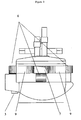
- Fig. 1 shows the panoramic picture of the furnace, including the new System, where are indicated: the roof (1), electrodes (2) EBT tapping hole or similar (3).
- Fig. 2 shows a side view of the furnace, where we can see: the tapping hole (3), the gas exits (6), the connect junction between the gas exits (9) all them converge in a main collector (7) and are connected to the exhausting fumes installation throw a duct connection (8).
- Fig. 3 shows a front view of the furnace, where are indicated: the tapping hole (3), the gas exits (6), the collectors to these gas exists (9) and the exhausting fumes installation duct connection (8)
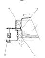
- Fig. 4 shows a sketch of the regulation and system control. It can be seen the open-close device (10) temperature- pressure sensor (12 and regulation circuit (11)
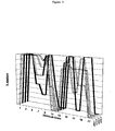
- Fig. 5 shows an example of control and conduction of the Process where, based on predetermined variables, different opening - closing devices are activated.
- the scrap or mix with HBI-DRI is loaded into the baskets as usually and unloaded inside the furnace shell previous roof opening.
- carbon or elements that carry carbon can be added to the scrap or during smelting process through carbon-oxygen injection devices.
- the regulation system activates the valves installed on the gas exits for this purpose, allowing automatically opening or closing each one of them individually, according to the signals received through the elements of control installed. By closing the hottest gas exits, is possible to lead the gases to the coldest zones, which transfer their energy to the scrap that remains solid.
- the control system enables us to identify when a zone of the furnace is melted and to proceed to the protection of the wall refractory and the panels by automatically adding carbon or other additives, which will generate the foamy slag that is needed for that purpose.
- the re-oxidation or post-combustion of its main gaseous component (CO) due the simultaneous oxygen injection from any furnace point will transform it to CO2.
- This gas is conducted - forced to the exit gas zone where there is still scrap that has not been melted, carrying out its preheating function. Data are taken from the different gas exists of the furnace, allowing know the process in real time and proceed to reload a new charge just in time.
Description
- System by which the gas flow that exists inside the electric arc furnace is directed with control across the scrap, which acts as a filter, where the gases release their energy, carrying out, in this way, the appropriate auto-pre heating of the loaded material inside the furnace vessel. The system is based on the location of at least two gas exits placed in the furnace vessel, and are connected to the exhausting fumes installation as set forth in
claim 1. - The invention is applied in the field of steel production and, inside the aforementioned, in the Electric Arc Furnace, which is powered by direct or alternating current, but can be applied to any type of furnace that uses the energy generated by the electric arc, as a main energetic source of the Process, just like some ferro-alloys industry.
- In the electric arc furnace used mainly for the steelmaking process, the transfer of the thermal energy from the arc to the scrap is realized, almost exclusively, by radiation.
- During the "bore down" process originated by the energy of the electric arc, and for the whole smelting period, a progressive hole or space is created between electrode(s) and scrap or mixture of scrap with ferric material. That hollow acts as priority route or way for hot gas evacuation. A big part of the energy contained in these gases is evacuated with them through the so called "fourth hole", a device which is placed on the top part of the furnace roof, due to the high speed at which the aforementioned gases leave the furnace, which is a consequence of their density as well as of the pressure difference that exists between the inside and outside.
- In order to optimize the energy consumption and increase productivity in electric the Electric Melt Shops, systems and/or techniques have been developed, which are based on different concepts, such as: the massive use of fossil energies; an attempt to confine gases inside to the furnace; autonomous vessel(s) station(s) scrap preheating; energy recovery from waste gas in order to preheating the scrap located it in vessels outside the furnace or feeding it continuously or on intermittent form.
-
US Pat.5375139 teaches an injection system, to modify the gas flow inside the furnace, preheating the scrap this way. This patent makes reference to another previous development with the same objective (EP Pat. 0462898 -US Pat.5166950 ). -
US Pat 6748004 teaches that it is usual to act on the control of the exhausting fumes installation, in order to maintain a correct depression and extract from the furnace the lowest energy possible, prolonging the stay of the gases inside the furnace, and preheating the scrap on this form. - The loss of energy in the processes indicated in the cases before mentioned (
US Pat. 5375139 and others) is high. The gases act "sweeping" and evacuating as much energy the bigger the injected gas volume is, due to the increase of pressure inside the vessel which increases the speed of evacuation, since the gas flow moves mainly through the spaces free of obstacles, which are "connected" to the "fourth hole" placed in the roof, an event that already happens from the beginning of the smelting period. - Furthermore, the gases, in these cases, only interact with the surface of the load, which is already very hot, which represents a low gas/scrap thermal gradient, and reduces the energy exchange or transfer.
- Other systems have been developed, which carry out the preheating outside the furnace vessel. The state of the Art (
US Pat. 6157664 ) shows a system to recovery the most of the energy that is evacuated from the furnace through the "fourth hole", and is based on scrap charged vessels connected in line between the aforementioned fourth hole and the exhausting fumes installation. - This patent exposes the operating capacity problems that a series of previous developments involve (
EP Pat. 225939 WO Pat. 95/12690 WO Pat. 96/32616 EP Pat 636698 - The state of the Art (
US Pat.6274081 ) also shows the development carried out regarding preheating the scrap, a preheating device through to a hopper placed outside the furnace shell (inserted in the roof of the aforementioned and connected with the exhaust fumes installation). In this case, the fumes discharged from the furnace, travel through the scrap, placed in the aforementioned hopper or shaft, releasing in this way a big part of their energy into it, carrying out the consequent preheating of the load. - (
EP Pat. 0190313 -WO Pat. 86/01230 - The scrap preheating systems outside the furnace, mentioned previously, present problems such as:
- Difficulty of obtaining a fluid bed through which gases can flow (
US 6157664 ) and all the operational problems indicated in this patent about the ones mentioned in it (EP 225939 - Difficulty of controlling the drop of scrap from the shaft - hopper to the shell of the furnace (
US 6274081 ) a situation that causes the breakage of electrodes. - There are also common inconveniences to the patents (
US Pat.6274081 -EP Pat. 0190313 ) in which the absence of scrap in the areas of the furnace that are farther away from the area where the load falls, causes the premature exposure of the vessel walls, which are exposed to the aggressive action of the electric arc. This circumstance prevents the usage of high electric power, decreasing productivity this way, at the same time it leads to a deterioration of the refractory. Moreover, in these Systems, it is not possible to use any kind of scrap, due to operational problems (uncontrolled load drop - not continuous feeding control) requiring to select the scrap quality, which involves the increase product's price. - The state Art (
US Pat. 5479434 A ) discloses a double furnace installation in which the scrap is pre-heated in a furnace vessel using hot gas from another operating furnace vessel in which melting takes place - Apart from the difficulties mentioned, these systems require huge facilities, which translate into high investment and maintenance costs.
- Taking into account all of these circumstances, the solution to the problems exposed, would involve the usage of an efficient system of preheating the load inside the furnace, avoiding the construction of onerous elements outside the vessel and its operational difficulty.
- The invention that is laid out here solves in a simple way, the aforementioned inconveniences, adding a new system for collecting, regulating and controlling the gases, that come from the combustion of the organic products included in the scrap as well as from the gases produced due to the combustion of additions supplied in solid as well as gaseous form. This invention allows us to conduct the gaseous flow from the place where these gases generate, to the exhausting fume installation, always through the solid load, creating close contact of the masses and carrying out in this way the process preheating process inside the furnace vessel.
- This invention, which process is exposed in
claim number 1 and relates apparatus inclaim number 2, is based on a full criteria change in the concept of scrap preheating, defining it as making thermal energy go through the scrap to produce the aforementioned effect. The State of the Art, which was previously synthesized, indicates that the preheating of the scrap in current facilities is carried out, almost every time in vessels or tunnel outside the electric arc furnace or vessel attached to the roof of the furnace. - Unlike the current options, with this invention, the preheating is made inside the furnace, as, from the moment the electrodes begin to transfer thermal energy, gases generated and blow into the furnace, which carry the energy that has not been transferred to the scrap, are not evacuated through the "fourth hole" but they are conducted - forced - directed downwards through the scrap, towards the holes or exits gas that have been placed around the shell of the furnace, instead of the roof of the furnace.
- With this invention, the opposition that the scrap puts up to the evacuation of gases, creates a noticeable decrease in the escape speed of the aforementioned, because, they cannot do it through the "fourth hole, since it has been blocked or eliminate, but by the gas exits made on the shell of the furnace, extending this way their stay in the vessel since they cannot escape naturally. This effect, added to the fact that the gases are taken and forced controllably through the scrap to the exits through the action of the fume treatment installation, allows its circulation to be carried out through the clear spaces in the scrap, achieving an efficient thermal exchange
- Due to the relatively small apparent mass of scrap placed between the electrode(s) and/or burner(s) and the gas exits, a fluid bed is achieved at all times which allows the correct control - regulation of the process, without needing to big powered exhaust system, which are typical of other furnace systems where gases must pass through a big pile of scrap, and the lack of permeability of it can sometimes prevent the correct fume evacuation, which causes them to flow to the exterior of the furnace.
- This system, also impedes that the air that ingress through the slag door, takes away energy from the process, since one of the gas exits- evacuation - suction zone is placed on the external top part of the tunnel door, where the door is usually placed so, this air, will be sucked up and conducted directly to the exhausting fumes installation, without coming in contact with the scrap, at the same time the said air is able to burn the CO, preventing possible explosions in the exhausting fumes installation and it also decreases fumes temperature.
- For means of a suitable alternating and modulating valves regulation that are placed on the system with such purpose is possible to obtain a rotary-sweeping movement of gas to increasing energetic yield and a good thermal homogeneity.
- The invention allows to place the oxy-burners in the upper part of the furnace shell where the danger of plugging is minimal and it also allows to maintain them active exclusively, when necessary, turning them Off and On at will, since there is no risk of the flame bouncing off. Currently, the oxy-burners must stay constantly ON to prevent blockages. Since this system prevents air from entering the furnace through the slag door, oxygen and gases can be supplied through any of the external methods (manipulators, etc.) positioned in a traditional way through said slag door, without needing to keep the fixed oxy-burner(s) operative constantly.
-
- Reduction of energy consumption, due to the use of the gas heat to preheat the scrap, as well as preventing air ingress through the slag door and contacting the scrap.
- Possibility of using higher electric power, as there are no hot spots, which implies a higher productivity.
- Increase in the stability of the arc, due to the thermal homogeneity, which translates into a better electric - thermal performance. Lower Power ON time.
- Oxygen and gas consumption reduction, due to the placement of the oxy-burners, which allows us to use them according to the requirements needed.
- Electrode consumption reduction - less oxidation - Less scrap drops that create breakages - Lower Power Off time for this reason.
- Refractory consumption reduction, due to: lower Power ON time, better thermal homogeneity and absence of hot spots.
- Increase in productivity (due all items before)
- Oxy-burners maintenance cost reduction due to their alternating use and upper position location.
- Due to in this system is not necessary to use the "fourth hole", the mechanical stability during the roof opening is improved, as there is a reduction of its total weight, in addition to easing the existing inertial problems on the opening/closing system.
- Because one of the gas exits is placed on the slag door of the furnace, this zone will stay free of scrap, thus avoiding the necessity to carry out cleaning operations, with the advantages this offers in safety, as well as in machinery savings on this matter.
- In this system, the general collector of the exhaust installation is placed at a height that is quite lower to that of conventional furnaces and under level of the roof. Therefore, there is no interference between the scrap basket and the shell of the furnace, allowing carrying out the load of liquid or solid scrap or slag, either from the from or from the side, as well as to the exchange of electrodes with ease and safety.
- The invention can be applied to any kind of electric conventional furnace, in new furnaces as well as revamping existing ones. The investment is considerably lower to that of the current systems with preheating outside the furnace.
- The adaptation of the system is carried out with a minimal production stop time.
- The drawings attached show an example, non -binding, of the lay out of the invention.
-
Fig. 1 shows the panoramic picture of the furnace, including the new System, where are indicated: the roof (1), electrodes (2) EBT tapping hole or similar (3). - It can be seen that in the roof there is not - though it is possible- a traditional fourth hole to conduct the fumes. The optional location of burners or double oxy -carbon injection devices are shown in the furnace shell (4) as well as the slag door (5). The extraction or conduction of gas, the main object of the invention, is carried out through the gas exits (6) placed on the furnace vessel (4)
-
Fig. 2 shows a side view of the furnace, where we can see: the tapping hole (3), the gas exits (6), the connect junction between the gas exits (9) all them converge in a main collector (7) and are connected to the exhausting fumes installation throw a duct connection (8). -
Fig. 3 shows a front view of the furnace, where are indicated: the tapping hole (3), the gas exits (6), the collectors to these gas exists (9) and the exhausting fumes installation duct connection (8) -
Fig. 4 shows a sketch of the regulation and system control. It can be seen the open-close device (10) temperature- pressure sensor (12 and regulation circuit (11) -
Fig. 5 shows an example of control and conduction of the Process where, based on predetermined variables, different opening - closing devices are activated. - The scrap or mix with HBI-DRI is loaded into the baskets as usually and unloaded inside the furnace shell previous roof opening.
- In order to accelerate the smelting process, carbon or elements that carry carbon, can be added to the scrap or during smelting process through carbon-oxygen injection devices.
- When roof furnace is turn on and closing the vessel electric energy is switch on and oxy-burners located preferably in the upper part of furnace are switch on. The preheating of the scrap is made initially from up to down, unlike in any other current furnace. Because the gases that carry energy cannot leave the furnace from its top part, they must do it through the gas exits made on the lower part of the furnace vessel, opposite to which the scrap remains until its complete melt.
- In the course of smelting period, the regulation system activates the valves installed on the gas exits for this purpose, allowing automatically opening or closing each one of them individually, according to the signals received through the elements of control installed. By closing the hottest gas exits, is possible to lead the gases to the coldest zones, which transfer their energy to the scrap that remains solid.
- The control system enables us to identify when a zone of the furnace is melted and to proceed to the protection of the wall refractory and the panels by automatically adding carbon or other additives, which will generate the foamy slag that is needed for that purpose. The re-oxidation or post-combustion of its main gaseous component (CO) due the simultaneous oxygen injection from any furnace point will transform it to CO2. This gas, as a consequence of the design of the furnace, is conducted - forced to the exit gas zone where there is still scrap that has not been melted, carrying out its preheating function. Data are taken from the different gas exists of the furnace, allowing know the process in real time and proceed to reload a new charge just in time.
- Once all the scrap or load has been melted, as is shown in
figure 5 , the Process takes place in the usual way to carry out the metallurgical and thermal work, up to the tilting time
Claims (3)
- Process to preheat scrap inside an electric arc furnace vessel whereby a gas flow is forced to go downward through the charged scrap in order to obtain an optimal scrap preheating and homogeneous thermal charge by sending more energy the coldest zone and said hot gas flow is driven towards the furnace cold spots zones in order to carry out both the gas flow control process for the scrap preheating and the scrap melting on a homogeneous and simultaneous manner wherein, at least two gas exists are positioned in the lower part of the furnace vessel including the slag door and the upper part to tap-hole zone (3) and are connected to the exhausting fumes installation and said gas exits comprise open-closing regulation system and temperature-pressure sensors, characterized in that the process comprises the following steps:- Charge scrap in the electric arc furnace vessel- Input electric energy to the electrode (s) and fossil energy- Control the temperature in each gas exit- Regulate the opening/closing level as a function of temperature-pressure values.- Once all scrap has been melted the process is similar to a conventional furnace by carry out a metallurgical and thermal work up to the tilting time
- Apparatus to carry out the process of claim 1 in order to preheat scrap inside an electric arc furnace vessel comprising at least two gas exits (6) positioned in the lower part of the furnace vessel including the slag door (5) and the upper part to tap-hole zone (3) and said gas exits are connected to the exhausting fumes installation, characterized in that said gas exists (6) comprise an open-closing valve or device (10) a regulation system (11) and temperature-pressure sensors.(12)
- Apparatus to preheat scrap inside an electric arc furnace according to claim 2 characterized in that the open-close devices, are activated through an electric, hydraulic or pneumatic regulation system.
Priority Applications (1)
| Application Number | Priority Date | Filing Date | Title |
|---|---|---|---|
| PL09384801T PL2107327T3 (en) | 2008-04-02 | 2009-03-13 | Thermal gas flow control system in the electric arc furnace |
Applications Claiming Priority (1)
| Application Number | Priority Date | Filing Date | Title |
|---|---|---|---|
| ES200801035A ES2332852B1 (en) | 2008-04-02 | 2008-04-02 | CONTROL SYSTEM OF THE THERMAL FLOW IN ARCO ELECTRIC OVEN. |
Publications (3)
| Publication Number | Publication Date |
|---|---|
| EP2107327A2 EP2107327A2 (en) | 2009-10-07 |
| EP2107327A3 EP2107327A3 (en) | 2011-04-20 |
| EP2107327B1 true EP2107327B1 (en) | 2012-05-30 |
Family
ID=40902139
Family Applications (1)
| Application Number | Title | Priority Date | Filing Date |
|---|---|---|---|
| EP20090384801 Not-in-force EP2107327B1 (en) | 2008-04-02 | 2009-03-13 | Thermal gas flow control system in the electric arc furnace |
Country Status (4)
| Country | Link |
|---|---|
| EP (1) | EP2107327B1 (en) |
| ES (2) | ES2332852B1 (en) |
| PL (1) | PL2107327T3 (en) |
| PT (1) | PT2107327E (en) |
Families Citing this family (2)
| Publication number | Priority date | Publication date | Assignee | Title |
|---|---|---|---|---|
| DE102011015211B4 (en) | 2011-03-25 | 2014-01-30 | Kautz Vorrichtungsbau Gmbh | Method of operating an electric arc furnace system and electric arc furnace system |
| CN203132356U (en) * | 2011-12-27 | 2013-08-14 | 钢铁普蓝特克股份有限公司 | Electric arc furnace |
Family Cites Families (16)
| Publication number | Priority date | Publication date | Assignee | Title |
|---|---|---|---|---|
| US4564388A (en) | 1984-08-02 | 1986-01-14 | Intersteel Technology, Inc. | Method for continuous steelmaking |
| DE3583508D1 (en) | 1985-12-20 | 1991-08-22 | Mannesmann Ag | METHOD FOR MELTING SCRAP OR THE LIKE. AND DEVICE FOR IMPLEMENTING THE METHOD. |
| SE460798B (en) * | 1986-12-12 | 1989-11-20 | Ssab Svenskt Stal Ab | SAFETY HANDLED SCRAP TO BE CHARGED TO AN OVEN |
| NO881415L (en) * | 1988-03-29 | 1989-10-02 | Elkem Technology | TREATMENT OF DUST AND ASH FROM COMBUSTION PLANT BY COPROCESSING WITH SPECIAL WASTE AND / OR METAL SCRAP. |
| WO1991010749A1 (en) * | 1990-01-10 | 1991-07-25 | Vinod Kumar | Method and apparatus for preheating scrap to high temperature |
| FR2663723B1 (en) | 1990-06-20 | 1995-07-28 | Air Liquide | PROCESS AND INSTALLATION FOR MELTING A LOAD IN THE OVEN. |
| US5375139A (en) | 1993-02-26 | 1994-12-20 | Bender; Manfred | Electric arc furnace insitu scrap preheating process |
| FR2704710B1 (en) * | 1993-04-30 | 1995-06-23 | Cegelec Metals Systems | Improved power converter device for supplying direct current to an electric arc furnace. |
| DE4325958A1 (en) | 1993-07-29 | 1995-02-02 | Mannesmann Ag | Method and device for inserting scrap |
| US5416792A (en) | 1993-11-05 | 1995-05-16 | Richard H. Logan | Preheat system |
| US5479434A (en) | 1994-03-11 | 1995-12-26 | Mannesmann Aktiengesellschaft | Double-hearth arc furnace for preheating scrap material and method of operating the same |
| JP3419950B2 (en) | 1995-04-14 | 2003-06-23 | 新日本製鐵株式会社 | Arc furnace preheating device |
| DE19634348A1 (en) | 1996-08-23 | 1998-02-26 | Arcmet Tech Gmbh | Melting unit with an electric arc furnace |
| IT1304326B1 (en) | 1997-03-26 | 2001-03-15 | Danieli Off Mecc | PRE-HEATED SCRAP LOADING SYSTEM BY MEANS OF A BASKET FOR ELECTRIC ARC OVEN |
| WO2001020046A1 (en) * | 1999-09-14 | 2001-03-22 | Danieli Technology, Inc. | High temperature premelting apparatus |
| US6748004B2 (en) | 2002-07-25 | 2004-06-08 | Air Liquide America, L.P. | Methods and apparatus for improved energy efficient control of an electric arc furnace fume extraction system |
-
2008
- 2008-04-02 ES ES200801035A patent/ES2332852B1/en active Active
-
2009
- 2009-03-13 ES ES09384801T patent/ES2387863T3/en active Active
- 2009-03-13 PT PT09384801T patent/PT2107327E/en unknown
- 2009-03-13 EP EP20090384801 patent/EP2107327B1/en not_active Not-in-force
- 2009-03-13 PL PL09384801T patent/PL2107327T3/en unknown
Also Published As
| Publication number | Publication date |
|---|---|
| ES2332852B1 (en) | 2010-07-16 |
| EP2107327A2 (en) | 2009-10-07 |
| PT2107327E (en) | 2012-08-28 |
| PL2107327T3 (en) | 2012-10-31 |
| EP2107327A3 (en) | 2011-04-20 |
| ES2332852A1 (en) | 2010-02-12 |
| ES2387863T3 (en) | 2012-10-03 |
Similar Documents
| Publication | Publication Date | Title |
|---|---|---|
| CA2603121A1 (en) | Operation of iron oxide recovery furnace for energy savings, volatile metal removal and slag control | |
| AU2014360665B2 (en) | Smelting process and apparatus | |
| CN201273767Y (en) | Multifunctional industrial furnace and continuous smelting system comprising the industrial furnace | |
| WO2010106466A1 (en) | Steel production facility | |
| CN101586908B (en) | Metallurgical oven | |
| CN108866270A (en) | A kind of steelmaking equipment | |
| KR20010074550A (en) | A method of relining a vessel | |
| CA2521689C (en) | Direct smelting plant and process | |
| BR112015000912B1 (en) | Method for initiating a melt bath-based casting process for a metalliferous material in a foundry container that defines a casting chamber and a melt metal production chamber | |
| CN108624739B (en) | Steelmaking equipment and smelting method for steelmaking by using scrap steel | |
| EP2107327B1 (en) | Thermal gas flow control system in the electric arc furnace | |
| WO2001004559A1 (en) | Equipment and method for arc melting of cold pig iron source | |
| CA2521705C (en) | Direct smelting plant | |
| EP3548640B1 (en) | Convertible metallurgical furnace and modular metallurgical plant comprising said furnace for conducting production processes for the production of metals in the molten state, in particualr steel or cast iron | |
| EP2788514B1 (en) | Starting a smelting process | |
| CN103392013B (en) | Manufacture molten iron and the method and apparatus of steel | |
| US4681537A (en) | Method and apparatus for continuously charging a steelmaking furnace | |
| JPH1137663A (en) | Method and equipment for melting cold iron source | |
| JP3650193B2 (en) | Method for melting metal raw materials | |
| WO2015122246A1 (en) | Preheating device and melting equipment used in melting furnaces and construction method for melting equipment | |
| JP3521277B2 (en) | Cold iron source melting method and melting equipment | |
| JP2000130946A (en) | Gas cupola for continuous molten delivery | |
| JP2001033171A (en) | Method and apparatus for smelting cold iron raw material | |
| AU2004228981B2 (en) | Direct smelting plant and process | |
| ITMI20071584A1 (en) | PROCESS PERFECTED FOR METALLURGICAL OVENS AND ITS APPARATUS |
Legal Events
| Date | Code | Title | Description |
|---|---|---|---|
| PUAI | Public reference made under article 153(3) epc to a published international application that has entered the european phase |
Free format text: ORIGINAL CODE: 0009012 |
|
| AK | Designated contracting states |
Kind code of ref document: A2 Designated state(s): AT BE BG CH CY CZ DE DK EE ES FI FR GB GR HR HU IE IS IT LI LT LU LV MC MK MT NL NO PL PT RO SE SI SK TR |
|
| AX | Request for extension of the european patent |
Extension state: AL BA RS |
|
| 17P | Request for examination filed |
Effective date: 20100120 |
|
| PUAL | Search report despatched |
Free format text: ORIGINAL CODE: 0009013 |
|
| AK | Designated contracting states |
Kind code of ref document: A3 Designated state(s): AT BE BG CH CY CZ DE DK EE ES FI FR GB GR HR HU IE IS IT LI LT LU LV MC MK MT NL NO PL PT RO SE SI SK TR |
|
| AX | Request for extension of the european patent |
Extension state: AL BA RS |
|
| RIC1 | Information provided on ipc code assigned before grant |
Ipc: C21C 5/52 20060101ALI20110317BHEP Ipc: F27B 3/26 20060101ALI20110317BHEP Ipc: C21C 5/46 20060101ALN20110317BHEP Ipc: F27B 3/08 20060101AFI20090803BHEP Ipc: F27D 13/00 20060101ALI20110317BHEP Ipc: F28C 1/08 20060101ALI20110317BHEP Ipc: F27D 17/00 20060101ALI20110317BHEP Ipc: C21C 5/56 20060101ALI20110317BHEP |
|
| 17Q | First examination report despatched |
Effective date: 20110607 |
|
| RIC1 | Information provided on ipc code assigned before grant |
Ipc: F27D 17/00 20060101ALI20110912BHEP Ipc: F27D 13/00 20060101ALI20110912BHEP Ipc: C21C 5/56 20060101ALI20110912BHEP Ipc: F27B 3/26 20060101ALI20110912BHEP Ipc: F28C 1/08 20060101ALI20110912BHEP Ipc: F27B 3/08 20060101AFI20110912BHEP Ipc: C21C 5/46 20060101ALN20110912BHEP Ipc: C21C 5/52 20060101ALI20110912BHEP |
|
| RIC1 | Information provided on ipc code assigned before grant |
Ipc: C21C 5/46 20060101ALN20111012BHEP Ipc: C21C 5/52 20060101ALI20111012BHEP Ipc: F28C 1/08 20060101ALI20111012BHEP Ipc: C21C 5/56 20060101ALI20111012BHEP Ipc: F27B 3/26 20060101ALI20111012BHEP Ipc: F27D 17/00 20060101ALI20111012BHEP Ipc: F27B 3/08 20060101AFI20111012BHEP Ipc: F27D 13/00 20060101ALI20111012BHEP |
|
| GRAP | Despatch of communication of intention to grant a patent |
Free format text: ORIGINAL CODE: EPIDOSNIGR1 |
|
| AKX | Designation fees paid |
Designated state(s): AT BE BG CH CY CZ DE DK EE ES FI FR GB GR HR HU IE IS IT LI LT LU LV MC MK MT NL NO PL PT RO SE SI SK TR |
|
| RIC1 | Information provided on ipc code assigned before grant |
Ipc: F27B 3/26 20060101ALI20111222BHEP Ipc: C21C 5/56 20060101ALI20111222BHEP Ipc: F27B 3/08 20060101AFI20111222BHEP Ipc: F27D 17/00 20060101ALI20111222BHEP Ipc: C21C 5/46 20060101ALN20111222BHEP Ipc: F28C 1/08 20060101ALI20111222BHEP Ipc: C21C 5/52 20060101ALI20111222BHEP Ipc: F27D 13/00 20060101ALI20111222BHEP |
|
| GRAS | Grant fee paid |
Free format text: ORIGINAL CODE: EPIDOSNIGR3 |
|
| GRAA | (expected) grant |
Free format text: ORIGINAL CODE: 0009210 |
|
| AK | Designated contracting states |
Kind code of ref document: B1 Designated state(s): AT BE BG CH CY CZ DE DK EE ES FI FR GB GR HR HU IE IS IT LI LT LU LV MC MK MT NL NO PL PT RO SE SI SK TR |
|
| REG | Reference to a national code |
Ref country code: GB Ref legal event code: FG4D |
|
| REG | Reference to a national code |
Ref country code: CH Ref legal event code: EP |
|
| REG | Reference to a national code |
Ref country code: AT Ref legal event code: REF Ref document number: 560254 Country of ref document: AT Kind code of ref document: T Effective date: 20120615 |
|
| REG | Reference to a national code |
Ref country code: IE Ref legal event code: FG4D |
|
| REG | Reference to a national code |
Ref country code: DE Ref legal event code: R096 Ref document number: 602009007327 Country of ref document: DE Effective date: 20120802 |
|
| REG | Reference to a national code |
Ref country code: RO Ref legal event code: EPE |
|
| REG | Reference to a national code |
Ref country code: PT Ref legal event code: SC4A Free format text: AVAILABILITY OF NATIONAL TRANSLATION Effective date: 20120821 |
|
| REG | Reference to a national code |
Ref country code: NL Ref legal event code: T3 |
|
| REG | Reference to a national code |
Ref country code: NO Ref legal event code: T2 Effective date: 20120530 |
|
| REG | Reference to a national code |
Ref country code: SE Ref legal event code: TRGR |
|
| REG | Reference to a national code |
Ref country code: ES Ref legal event code: FG2A Ref document number: 2387863 Country of ref document: ES Kind code of ref document: T3 Effective date: 20121003 |
|
| REG | Reference to a national code |
Ref country code: LT Ref legal event code: MG4D Effective date: 20120523 |
|
| REG | Reference to a national code |
Ref country code: GR Ref legal event code: EP Ref document number: 20120401696 Country of ref document: GR Effective date: 20120903 |
|
| PG25 | Lapsed in a contracting state [announced via postgrant information from national office to epo] |
Ref country code: CY Free format text: LAPSE BECAUSE OF FAILURE TO SUBMIT A TRANSLATION OF THE DESCRIPTION OR TO PAY THE FEE WITHIN THE PRESCRIBED TIME-LIMIT Effective date: 20120530 Ref country code: LT Free format text: LAPSE BECAUSE OF FAILURE TO SUBMIT A TRANSLATION OF THE DESCRIPTION OR TO PAY THE FEE WITHIN THE PRESCRIBED TIME-LIMIT Effective date: 20120530 Ref country code: IS Free format text: LAPSE BECAUSE OF FAILURE TO SUBMIT A TRANSLATION OF THE DESCRIPTION OR TO PAY THE FEE WITHIN THE PRESCRIBED TIME-LIMIT Effective date: 20120930 |
|
| REG | Reference to a national code |
Ref country code: PL Ref legal event code: T3 |
|
| PG25 | Lapsed in a contracting state [announced via postgrant information from national office to epo] |
Ref country code: SI Free format text: LAPSE BECAUSE OF FAILURE TO SUBMIT A TRANSLATION OF THE DESCRIPTION OR TO PAY THE FEE WITHIN THE PRESCRIBED TIME-LIMIT Effective date: 20120530 Ref country code: HR Free format text: LAPSE BECAUSE OF FAILURE TO SUBMIT A TRANSLATION OF THE DESCRIPTION OR TO PAY THE FEE WITHIN THE PRESCRIBED TIME-LIMIT Effective date: 20120530 Ref country code: LV Free format text: LAPSE BECAUSE OF FAILURE TO SUBMIT A TRANSLATION OF THE DESCRIPTION OR TO PAY THE FEE WITHIN THE PRESCRIBED TIME-LIMIT Effective date: 20120530 |
|
| PG25 | Lapsed in a contracting state [announced via postgrant information from national office to epo] |
Ref country code: SK Free format text: LAPSE BECAUSE OF FAILURE TO SUBMIT A TRANSLATION OF THE DESCRIPTION OR TO PAY THE FEE WITHIN THE PRESCRIBED TIME-LIMIT Effective date: 20120530 Ref country code: DK Free format text: LAPSE BECAUSE OF FAILURE TO SUBMIT A TRANSLATION OF THE DESCRIPTION OR TO PAY THE FEE WITHIN THE PRESCRIBED TIME-LIMIT Effective date: 20120530 Ref country code: EE Free format text: LAPSE BECAUSE OF FAILURE TO SUBMIT A TRANSLATION OF THE DESCRIPTION OR TO PAY THE FEE WITHIN THE PRESCRIBED TIME-LIMIT Effective date: 20120530 |
|
| PLBE | No opposition filed within time limit |
Free format text: ORIGINAL CODE: 0009261 |
|
| STAA | Information on the status of an ep patent application or granted ep patent |
Free format text: STATUS: NO OPPOSITION FILED WITHIN TIME LIMIT |
|
| 26N | No opposition filed |
Effective date: 20130301 |
|
| REG | Reference to a national code |
Ref country code: DE Ref legal event code: R097 Ref document number: 602009007327 Country of ref document: DE Effective date: 20130301 |
|
| REG | Reference to a national code |
Ref country code: HU Ref legal event code: AG4A Ref document number: E016022 Country of ref document: HU |
|
| PG25 | Lapsed in a contracting state [announced via postgrant information from national office to epo] |
Ref country code: MC Free format text: LAPSE BECAUSE OF NON-PAYMENT OF DUE FEES Effective date: 20130331 |
|
| REG | Reference to a national code |
Ref country code: CH Ref legal event code: PL |
|
| REG | Reference to a national code |
Ref country code: IE Ref legal event code: MM4A |
|
| PG25 | Lapsed in a contracting state [announced via postgrant information from national office to epo] |
Ref country code: LI Free format text: LAPSE BECAUSE OF NON-PAYMENT OF DUE FEES Effective date: 20130331 Ref country code: IE Free format text: LAPSE BECAUSE OF NON-PAYMENT OF DUE FEES Effective date: 20130313 Ref country code: CH Free format text: LAPSE BECAUSE OF NON-PAYMENT OF DUE FEES Effective date: 20130331 |
|
| PG25 | Lapsed in a contracting state [announced via postgrant information from national office to epo] |
Ref country code: MT Free format text: LAPSE BECAUSE OF FAILURE TO SUBMIT A TRANSLATION OF THE DESCRIPTION OR TO PAY THE FEE WITHIN THE PRESCRIBED TIME-LIMIT Effective date: 20120530 |
|
| PGFP | Annual fee paid to national office [announced via postgrant information from national office to epo] |
Ref country code: HU Payment date: 20150310 Year of fee payment: 7 Ref country code: BG Payment date: 20150325 Year of fee payment: 7 Ref country code: CZ Payment date: 20150304 Year of fee payment: 7 Ref country code: NL Payment date: 20150326 Year of fee payment: 7 Ref country code: FI Payment date: 20150327 Year of fee payment: 7 |
|
| PGFP | Annual fee paid to national office [announced via postgrant information from national office to epo] |
Ref country code: LU Payment date: 20150402 Year of fee payment: 7 Ref country code: PL Payment date: 20150305 Year of fee payment: 7 Ref country code: GR Payment date: 20150330 Year of fee payment: 7 Ref country code: SE Payment date: 20150327 Year of fee payment: 7 Ref country code: AT Payment date: 20150304 Year of fee payment: 7 |
|
| PG25 | Lapsed in a contracting state [announced via postgrant information from national office to epo] |
Ref country code: MK Free format text: LAPSE BECAUSE OF FAILURE TO SUBMIT A TRANSLATION OF THE DESCRIPTION OR TO PAY THE FEE WITHIN THE PRESCRIBED TIME-LIMIT Effective date: 20120530 |
|
| PGFP | Annual fee paid to national office [announced via postgrant information from national office to epo] |
Ref country code: NO Payment date: 20150327 Year of fee payment: 7 |
|
| PGFP | Annual fee paid to national office [announced via postgrant information from national office to epo] |
Ref country code: BE Payment date: 20150327 Year of fee payment: 7 |
|
| REG | Reference to a national code |
Ref country code: FR Ref legal event code: PLFP Year of fee payment: 8 |
|
| PG25 | Lapsed in a contracting state [announced via postgrant information from national office to epo] |
Ref country code: BE Free format text: LAPSE BECAUSE OF NON-PAYMENT OF DUE FEES Effective date: 20160331 |
|
| REG | Reference to a national code |
Ref country code: NO Ref legal event code: MMEP |
|
| PG25 | Lapsed in a contracting state [announced via postgrant information from national office to epo] |
Ref country code: LU Free format text: LAPSE BECAUSE OF NON-PAYMENT OF DUE FEES Effective date: 20160313 Ref country code: FI Free format text: LAPSE BECAUSE OF NON-PAYMENT OF DUE FEES Effective date: 20160313 |
|
| REG | Reference to a national code |
Ref country code: SE Ref legal event code: EUG |
|
| REG | Reference to a national code |
Ref country code: AT Ref legal event code: MM01 Ref document number: 560254 Country of ref document: AT Kind code of ref document: T Effective date: 20160313 |
|
| REG | Reference to a national code |
Ref country code: NL Ref legal event code: MM Effective date: 20160401 |
|
| PG25 | Lapsed in a contracting state [announced via postgrant information from national office to epo] |
Ref country code: CZ Free format text: LAPSE BECAUSE OF NON-PAYMENT OF DUE FEES Effective date: 20160313 Ref country code: SE Free format text: LAPSE BECAUSE OF NON-PAYMENT OF DUE FEES Effective date: 20160314 |
|
| PG25 | Lapsed in a contracting state [announced via postgrant information from national office to epo] |
Ref country code: NL Free format text: LAPSE BECAUSE OF NON-PAYMENT OF DUE FEES Effective date: 20160401 Ref country code: HU Free format text: LAPSE BECAUSE OF NON-PAYMENT OF DUE FEES Effective date: 20160314 Ref country code: NO Free format text: LAPSE BECAUSE OF NON-PAYMENT OF DUE FEES Effective date: 20160331 |
|
| REG | Reference to a national code |
Ref country code: GR Ref legal event code: ML Ref document number: 20120401696 Country of ref document: GR Effective date: 20161006 |
|
| PG25 | Lapsed in a contracting state [announced via postgrant information from national office to epo] |
Ref country code: AT Free format text: LAPSE BECAUSE OF NON-PAYMENT OF DUE FEES Effective date: 20160313 Ref country code: BG Free format text: LAPSE BECAUSE OF NON-PAYMENT OF DUE FEES Effective date: 20160930 Ref country code: GR Free format text: LAPSE BECAUSE OF NON-PAYMENT OF DUE FEES Effective date: 20161006 |
|
| REG | Reference to a national code |
Ref country code: FR Ref legal event code: PLFP Year of fee payment: 9 |
|
| PGFP | Annual fee paid to national office [announced via postgrant information from national office to epo] |
Ref country code: FR Payment date: 20170327 Year of fee payment: 9 Ref country code: RO Payment date: 20170308 Year of fee payment: 9 |
|
| PG25 | Lapsed in a contracting state [announced via postgrant information from national office to epo] |
Ref country code: PL Free format text: LAPSE BECAUSE OF NON-PAYMENT OF DUE FEES Effective date: 20160313 |
|
| PGFP | Annual fee paid to national office [announced via postgrant information from national office to epo] |
Ref country code: PT Payment date: 20170306 Year of fee payment: 9 Ref country code: GB Payment date: 20170327 Year of fee payment: 9 |
|
| PGFP | Annual fee paid to national office [announced via postgrant information from national office to epo] |
Ref country code: TR Payment date: 20170303 Year of fee payment: 9 Ref country code: IT Payment date: 20170324 Year of fee payment: 9 Ref country code: ES Payment date: 20170222 Year of fee payment: 9 |
|
| PGFP | Annual fee paid to national office [announced via postgrant information from national office to epo] |
Ref country code: DE Payment date: 20170329 Year of fee payment: 9 |
|
| REG | Reference to a national code |
Ref country code: DE Ref legal event code: R119 Ref document number: 602009007327 Country of ref document: DE |
|
| PG25 | Lapsed in a contracting state [announced via postgrant information from national office to epo] |
Ref country code: PT Free format text: LAPSE BECAUSE OF NON-PAYMENT OF DUE FEES Effective date: 20180913 Ref country code: RO Free format text: LAPSE BECAUSE OF NON-PAYMENT OF DUE FEES Effective date: 20180313 |
|
| GBPC | Gb: european patent ceased through non-payment of renewal fee |
Effective date: 20180313 |
|
| PG25 | Lapsed in a contracting state [announced via postgrant information from national office to epo] |
Ref country code: DE Free format text: LAPSE BECAUSE OF NON-PAYMENT OF DUE FEES Effective date: 20181002 |
|
| PG25 | Lapsed in a contracting state [announced via postgrant information from national office to epo] |
Ref country code: GB Free format text: LAPSE BECAUSE OF NON-PAYMENT OF DUE FEES Effective date: 20180313 Ref country code: IT Free format text: LAPSE BECAUSE OF NON-PAYMENT OF DUE FEES Effective date: 20180313 |
|
| PG25 | Lapsed in a contracting state [announced via postgrant information from national office to epo] |
Ref country code: FR Free format text: LAPSE BECAUSE OF NON-PAYMENT OF DUE FEES Effective date: 20180331 |
|
| REG | Reference to a national code |
Ref country code: ES Ref legal event code: FD2A Effective date: 20190911 |
|
| PG25 | Lapsed in a contracting state [announced via postgrant information from national office to epo] |
Ref country code: ES Free format text: LAPSE BECAUSE OF NON-PAYMENT OF DUE FEES Effective date: 20180314 |
|
| PG25 | Lapsed in a contracting state [announced via postgrant information from national office to epo] |
Ref country code: TR Free format text: LAPSE BECAUSE OF NON-PAYMENT OF DUE FEES Effective date: 20180313 |