EP2107242A1 - Beverage dispensing apparatus comprising a solenoid pump and method of controlling the solenoid pump - Google Patents
Beverage dispensing apparatus comprising a solenoid pump and method of controlling the solenoid pump Download PDFInfo
- Publication number
- EP2107242A1 EP2107242A1 EP08153916A EP08153916A EP2107242A1 EP 2107242 A1 EP2107242 A1 EP 2107242A1 EP 08153916 A EP08153916 A EP 08153916A EP 08153916 A EP08153916 A EP 08153916A EP 2107242 A1 EP2107242 A1 EP 2107242A1
- Authority
- EP
- European Patent Office
- Prior art keywords
- spring
- fluid
- flow rate
- solenoid pump
- signal
- Prior art date
- Legal status (The legal status is an assumption and is not a legal conclusion. Google has not performed a legal analysis and makes no representation as to the accuracy of the status listed.)
- Granted
Links
- 235000013361 beverage Nutrition 0.000 title claims abstract description 46
- 238000000034 method Methods 0.000 title claims description 11
- 239000012530 fluid Substances 0.000 claims abstract description 81
- 238000005086 pumping Methods 0.000 claims abstract description 39
- 238000010438 heat treatment Methods 0.000 claims description 6
- 230000004044 response Effects 0.000 claims description 5
- 238000006073 displacement reaction Methods 0.000 claims description 4
- 230000008901 benefit Effects 0.000 description 6
- 230000007246 mechanism Effects 0.000 description 5
- 241001122767 Theaceae Species 0.000 description 4
- 230000008859 change Effects 0.000 description 4
- 230000001276 controlling effect Effects 0.000 description 4
- 238000000819 phase cycle Methods 0.000 description 4
- 239000002775 capsule Substances 0.000 description 2
- 238000005259 measurement Methods 0.000 description 2
- 238000005057 refrigeration Methods 0.000 description 2
- 235000014214 soft drink Nutrition 0.000 description 2
- XLYOFNOQVPJJNP-UHFFFAOYSA-N water Substances O XLYOFNOQVPJJNP-UHFFFAOYSA-N 0.000 description 2
- 230000009471 action Effects 0.000 description 1
- 230000003213 activating effect Effects 0.000 description 1
- 230000004913 activation Effects 0.000 description 1
- 230000006835 compression Effects 0.000 description 1
- 238000007906 compression Methods 0.000 description 1
- 230000010485 coping Effects 0.000 description 1
- 230000002596 correlated effect Effects 0.000 description 1
- 238000013500 data storage Methods 0.000 description 1
- 230000001419 dependent effect Effects 0.000 description 1
- 238000013461 design Methods 0.000 description 1
- 230000001627 detrimental effect Effects 0.000 description 1
- 239000008187 granular material Substances 0.000 description 1
- 235000012171 hot beverage Nutrition 0.000 description 1
- 239000007788 liquid Substances 0.000 description 1
- 239000000696 magnetic material Substances 0.000 description 1
- 239000000463 material Substances 0.000 description 1
- 238000012544 monitoring process Methods 0.000 description 1
- 230000000737 periodic effect Effects 0.000 description 1
- 238000012545 processing Methods 0.000 description 1
- 230000009467 reduction Effects 0.000 description 1
- 230000035939 shock Effects 0.000 description 1
- 238000004804 winding Methods 0.000 description 1
Images

Classifications
-
- F—MECHANICAL ENGINEERING; LIGHTING; HEATING; WEAPONS; BLASTING
- F04—POSITIVE - DISPLACEMENT MACHINES FOR LIQUIDS; PUMPS FOR LIQUIDS OR ELASTIC FLUIDS
- F04B—POSITIVE-DISPLACEMENT MACHINES FOR LIQUIDS; PUMPS
- F04B17/00—Pumps characterised by combination with, or adaptation to, specific driving engines or motors
- F04B17/03—Pumps characterised by combination with, or adaptation to, specific driving engines or motors driven by electric motors
- F04B17/04—Pumps characterised by combination with, or adaptation to, specific driving engines or motors driven by electric motors using solenoids
- F04B17/042—Pumps characterised by combination with, or adaptation to, specific driving engines or motors driven by electric motors using solenoids the solenoid motor being separated from the fluid flow
- F04B17/044—Pumps characterised by combination with, or adaptation to, specific driving engines or motors driven by electric motors using solenoids the solenoid motor being separated from the fluid flow using solenoids directly actuating the piston
-
- F—MECHANICAL ENGINEERING; LIGHTING; HEATING; WEAPONS; BLASTING
- F04—POSITIVE - DISPLACEMENT MACHINES FOR LIQUIDS; PUMPS FOR LIQUIDS OR ELASTIC FLUIDS
- F04B—POSITIVE-DISPLACEMENT MACHINES FOR LIQUIDS; PUMPS
- F04B39/00—Component parts, details, or accessories, of pumps or pumping systems specially adapted for elastic fluids, not otherwise provided for in, or of interest apart from, groups F04B25/00 - F04B37/00
- F04B39/0027—Pulsation and noise damping means
-
- F—MECHANICAL ENGINEERING; LIGHTING; HEATING; WEAPONS; BLASTING
- F04—POSITIVE - DISPLACEMENT MACHINES FOR LIQUIDS; PUMPS FOR LIQUIDS OR ELASTIC FLUIDS
- F04B—POSITIVE-DISPLACEMENT MACHINES FOR LIQUIDS; PUMPS
- F04B49/00—Control, e.g. of pump delivery, or pump pressure of, or safety measures for, machines, pumps, or pumping installations, not otherwise provided for, or of interest apart from, groups F04B1/00 - F04B47/00
- F04B49/06—Control using electricity
- F04B49/065—Control using electricity and making use of computers
Landscapes
- Engineering & Computer Science (AREA)
- Mechanical Engineering (AREA)
- General Engineering & Computer Science (AREA)
- Physics & Mathematics (AREA)
- Fluid Mechanics (AREA)
- Computer Hardware Design (AREA)
- Devices For Dispensing Beverages (AREA)
- Apparatus For Making Beverages (AREA)
- Control Of Positive-Displacement Pumps (AREA)
- Electromagnetic Pumps, Or The Like (AREA)
- Beverage Vending Machines With Cups, And Gas Or Electricity Vending Machines (AREA)
Abstract
Description
- The present invention relates to a beverage dispensing apparatus comprising a solenoid pump coupled between a fluid inlet and a fluid outlet for pumping the fluid from said inlet to said outlet, said pump comprising a spring-loaded linear pumping member axially displaceable between a spring-loaded stop position and a spring-released position, and a controller for the solenoid pump.
- The present invention further relates to a method for controlling a solenoid pump in such an apparatus.
- Beverage dispensing apparatuses are commonplace in both domestic and commercial environments. Such apparatuses are popular because they can dispense beverages on-demand, such as hot drinks, e.g. coffee or tea, in case of the apparatus comprising a heating stage, or chilled drinks, e.g. soft drinks or water, in case of the apparatus comprising a refrigeration stage. Such apparatuses are well-known in the art. An example of such an apparatus can for instance be found in
US patent application No. 2007/181004 . - Solenoid pumps are commonly used in such apparatuses because of their low cost and reliability. However, the use of a solenoid pump in a beverage dispensing apparatus is not without problems. For instance, the solenoid pump can be very noisy, which may be distracting and/or displeasing to the user of the beverage dispensing apparatus. Such noise pollution is caused by the fact that the axially displaceable, spring-loaded pumping member of the solenoid pump, e.g. a piston, impacts upon its end position in the de-energized position of the member, i.e. the position into which the displaceable pumping member is forced by the released spring.
- There have been several efforts to reduce the noise produced by solenoid pumps. For instance,
US patent No. 5,073,095 and prior art citations therein disclose an electromagnetic pump, in which the end position comprises an annular washer to cushion the impact of the piston, thus reducing the noise produced by the electromagnetic pump. An alternative arrangement for reducing the noise produced by the pump is disclosed in French patent applicationFR 2,847,708 A1 - The present invention seeks to provide a relatively quiet beverage dispensing apparatus according to the opening paragraph.
- The present invention further seeks to provide a method for controlling a beverage dispensing apparatus according to the opening paragraph such that the beverage dispensing apparatus can be operated relatively quietly.
- According to an aspect of the present invention, there is provided a beverage dispensing apparatus comprising a solenoid pump coupled between a fluid inlet and a fluid outlet for pumping the fluid from said inlet to said outlet, said pump comprising a spring-loaded linear pumping member axially displaceable between a spring-loaded position and a spring-released end position and a controller for the solenoid pump, said controller being arranged to energize the pumping member into an intermediate position between the spring-released end position and the spring-loaded position.
- The present invention is based on the realization that the impact of the pumping member on the spring released end position of the pump can be reduced by reducing the axial displacement of the pumping member from the spring released end position. This limits the amount of energy stored in the spring, and thus limits the impact of the pumping member on the end position, i.e. the stop, of the solenoid pump.
- Preferably, the controller is responsive to an alternating current, and arranged to provide the solenoid pump with an energizing signal substantially in each period of the alternating current.
- In an embodiment, the energizing signal is a phase-angled sinusoidal signal, with the amount of energy being defined by the phase-angle. This has the advantage that the energizing signal can be easily derived from the alternating current by selecting the rectified part of the relevant half-period of the alternating current as defined by the phase angle.
- Energizing the solenoid pump in substantially every period of the alternating current has advantages over solenoid pumps that are controlled by means of a so-called burst fire control mechanism, in which the pump is energized in a subset of a predefined number of alternating current periods, e.g. 3 of 10 periods or 5 of 10 periods.
- It has been found that a burst fire control mechanism causes substantial fluctuations in the fluid flow through the beverage dispensing apparatus, which can have a detrimental impact on the accuracy of the measurement of the fluid flow. This is especially true when the fluid flow meter of the beverage dispensing apparatus comprises a paddle wheel, because the paddle wheel is incapable of coping with the periodic burst-type increases in the fluid flow, which cause the paddle wheel to spin, thereby reducing the accuracy of the fluid flow measurement by the fluid flow meter. Such fluctuations are avoided by energizing the solenoid pump in substantially every period of the alternating current, which causes the fluid flow rate to become substantially constant over said periods.
- It can be important to obtain an accurate reading of the fluid flow rate, for instance when the fluid flow rate is used to ensure that a high quality beverage is dispensed. For example, in case of the beverage dispensing apparatus comprising a holder for receiving a beverage brewing product such as coffee or tea e.g. in a pad, a capsule or another suitable type of beverage product package, the control of the fluid flow rate may be of significant importance to ensuring the correct strength of the beverage brewed by the apparatus. To this end, the measured flow rate may be used as a control input for the controller, wherein the controller is arranged to set the amount of energy of the energizing signal in response to a fluid flow rate indication signal, e.g. by adjusting the energizing signal based on a discrepancy between the fluid flow rate indication signal and a required fluid flow rate, which may be user-defined. For instance, a user may require a strongly brewed beverage, which may be achieved by reducing the flow rate of the fluid through a beverage brewing product.
- According to a further aspect of the present invention, there is provided a method of controlling a solenoid pump for pumping a fluid from a fluid inlet to a fluid outlet of a beverage dispensing apparatus, said pump comprising a spring-loaded linear pumping member axially displaceable between a spring-loaded stop position and a spring-released position, the method comprising energizing the pumping member into an intermediate position between the spring-released position and the spring-loaded stop position. A solenoid pump operated in accordance with the method of the present invention benefits from reduced noise levels during operation, as previously explained. In addition, if the pump is energized in substantially every control cycle, e.g. a phase half-cycle of an alternating current, an additional advantage of providing a substantially constant fluid flow rate is achieved, as previously explained.
- Embodiments of the invention are described in more detail and by way of non-limiting examples with reference to the accompanying drawings, wherein
-
FIG. 1 schematically depicts a beverage dispensing apparatus in accordance with an embodiment of the present invention; -
FIG. 2 schematically depicts an aspect of the beverage dispensing apparatus in accordance with an embodiment of the present invention in greater detail; -
FIG. 3 schematically depicts an aspect of an alternative beverage dispensing apparatus in accordance with an embodiment of the present invention; -
FIG. 4 schematically depicts a control signal for a solenoid pump in accordance with an embodiment of the present invention; and -
FIG. 5 schematically depicts a control signal for a solenoid pump in accordance with an alternative embodiment of the present invention. - It should be understood that the Figures are merely schematic and are not drawn to scale. It should also be understood that the same reference numerals are used throughout the Figures to indicate the same or similar parts.
-
FIG. 1 schematically depicts a beverage dispensingapparatus 100 in accordance with an embodiment of the present invention. Thebeverage dispensing apparatus 100 comprises afluid inlet 102, e.g. an inlet for receiving a liquid such as water or a soft drink, and afluid outlet 104 for dispensing a beverage to a user of thebeverage dispensing apparatus 100. Asolenoid pump 106 is arranged between thefluid inlet 102 and thefluid outlet 104 for pumping a fluid from the inlet to the outlet. Thesolenoid pump 106 is controlled by acontroller 108, which will be described in more detail later. - In addition, the
beverage dispensing apparatus 100 may have any suitable configuration, since the embodiment of thebeverage dispensing apparatus 100 is not critical to the present invention. For instance, the conduit between thefluid inlet 102 and thefluid outlet 104 may further comprise aflow meter 110, which may be a paddle wheel-based flow meter, atemperature adjustment stage 112, which may be a fluid heating stage and/or a fluid refrigeration stage, atemperature sensor 116 and aholder 118 for receiving a beverage brewing product, e.g. coffee or tea, which may be placed in theholder 118 in the form of loose material, e.g. coffee granules or tea leaves, or packaged in a pad, capsule or other suitable package. Other embodiments are equally suitable. - The
controller 108 is arranged to provide thesolenoid pump 106 with acontrol signal 122. Thecontrol signal 122 is defined by thecontroller 108 to ensure that the fluid presented at thefluid outlet 104 has the required properties, such as flow rate and/or temperature. For instance, control of the flow rate may be important to ensure that the fluid flow rate is relatively constant, and at a rate that is experienced as pleasant by the user of thebeverage dispensing apparatus 100. Control of the flow rate may also be important to ensure that, in case thebeverage dispensing apparatus 100 comprises a beveragebrewing product holder 116, the strength of the beverage presented at thefluid outlet 104 is in accordance with user requirements. - Control of the flow rate may also be important to ensure that a
temperature adjustment stage 112 is capable of appropriately adjusting the temperature of the fluid. In case of an excessive flow rate, thetemperature adjustment stage 112 may have insufficient capacity to sufficiently adjust this temperature, leading to a perceived loss of quality by the user of thebeverage dispensing apparatus 100. - To this end, the
controller 108 may be responsive to signals indicative of the read-out data from thefluid flow meter 110 and/or thetemperature sensor 116,i.e. signals controller 108 may be arranged to compare such a feedback signal,e.g. feedback signal 124 from thefluid flow meter 110 indicating an actual fluid flow rate, with a predefined fluid flow rate, and be arranged to adjust thecontrol signal 122 in response to a determined discrepancy between the actual fluid flow rate and the predefined fluid flow rate. The predefined fluid flow rate may correspond with a user-selected fluid output requirement, and may be stored in any suitable data storage medium, e.g. a SRAM, a ROM, a look-up table and so on. Thebeverage dispensing apparatus 100 may comprise auser interface 130, e.g. one or more buttons, for allowing a user to define such a fluid output requirement, e.g. the strength or temperature of a beverage to be dispensed. - In an embodiment, the controller may be arranged to monitor the supply current, e.g. to detect fluctuations in a power supply current or voltage, e.g. flicker or other types of variations, and adjust the
control signal 122 accordingly to maintain a required fluid flow rate. Such fluctuations in the power supply may for instance occur when the temperature adjustingstage 112, e.g. heating elements in a heating stage, switches on or off. - In a further embodiment, the
apparatus 100 comprises a temperature sensor (not shown) for sensing a temperature of the solenoid of thesolenoid pump 106, and for compensating for a change in the resistance of the windings of the solenoid caused by a change in the solenoid temperature to ensure that a required flow rate is maintained. - It should be appreciated that the above examples of possible control mechanisms of the
solenoid pump 106 are non-limiting examples only. Other suitable control principles involving thecontroller 108 will be apparent to the skilled person, and it should be understood that combinations of the suitable control mechanisms including the disclosed control mechanisms are also feasible. Thecontroller 108 may be a discrete component of thebeverage dispensing apparatus 100 realized in hardware. Alternatively, thecontroller 108 may be a part of asignal processor 120, which may be further arranged to implement other controllers, e.g. acontroller 114 for controlling thetemperature adjustment stage 112, and for processing feedback signals such as thefeedback signal 124 from thefluid flow meter 110 and thefeedback signal 126 from thetemperature sensor 116. Thecontroller 108 may be implemented in software on such asignal processor 120. - The inventive control principle of the
solenoid pump 106 in thebeverage dispensing apparatus 100 is explained in more detail inFIG. 2 . InFIG. 2 , thesolenoid pump 106 comprises afluid inlet 202 and afluid outlet 204, which may comprise valves (not shown). Thesolenoid pump 106 further comprises an axiallydisplaceable pumping member 206, e.g. a piston or a diaphragm, which is axially displaceable over anaxis 208 under control of thesolenoid 220. To this end, the pumpingmember 206 may comprise a magnetic material. Aspring 210 is mounted behind the pumpingmember 206 such that thespring 210 is compressed when the pumpingmember 206 is moved towards theinlet 202 under control of thesolenoid 220. - In
FIG. 1 and 2 , thesolenoid pump 106 is configured to have a T-junction arrangement between theinlet 202, theoutlet 204 and thechamber 212 of thesolenoid pump 106. However, it is emphasized this arrangement is shown by way of non-limiting example only, and that other embodiments of thesolenoid pump 106 are equally feasible, such as an alternative arrangement in which thesolenoid pump 106 of the beverage dispensing apparatus ofFIG.1 is replaced with a solenoid pump as shown inFIG. 3 . In thesolenoid pump 106 shown inFIG. 3 , thechamber 212 is placed between theinlet 202 and theoutlet 204. Such a solenoid pump is also well-known; see for instanceUS patent No. 6,942,470 . - The pumping
member 206 can be axially moved between anend position 230, in which thespring 210 has released its tension, and a spring-loadedposition 240 under control of thesolenoid 220, in which thespring 210 is fully compressed. Theend position 230 may comprise a stop, e.g. a shock absorbing member. The displacement of the pumpingmember 206 fromend position 230 towards the spring loadedposition 240 causes a fluid to be sucked into thechamber 212 of thesolenoid pump 106 throughinlet 202, whereas the release of the tension in thespring 210 causes the pumpingmember 206 to be displaced towards theend position 230, thereby pumping the fluid collected in thechamber 212 through theoutlet 204. - As has been explained previously, the release of the tension in the
spring 210 during the pumping action of thesolenoid pump 106 accelerates the pumpingmember 206 towards theend position 230, with the impact of the pumpingmember 210 at theend position 230 creating a substantial amount of noise. To this end, in accordance with the present invention, thecontroller 108 is arranged to control thesolenoid 220 such that the pumping member is not fully retracted into thechamber 212, but displaced from theend position 230 to anintermediate position 235 in between theend position 230 and the spring-loadedposition 240. In other words, the amount of energy stored in the form of tension (compression) of thespring 210 is less than the maximum amount of energy that can be stored in thespring 210. Consequently, when thespring 210 is released, the force on the pumpingmember 206 is reduced compared to the force generated by a fully loadedspring 210, thus reducing the impact of the pumpingmember 206 on theend position 230 and the noise generated by this impact. - A further advantage of partially retracting the pumping
member 206 into thechamber 212 is that the fluid flow rate generated by thesolenoid pump 106 may be adjusted whilst still activating thesolenoid pump 106 in each phase cycle of an alternating current powering thebeverage dispensing apparatus 100 and/or thecontroller 108. This may be achieved by dynamically adjusting theintermediate position 235, e.g. moving it towards theend position 230 or towards the spring-loadedposition 240. This is not possible in solenoid pumps in which the amount of force exerted by thespring 210 on the pumpingmember 206 cannot be adjusted. In such pumps, the flow rate must be adjusted by altering the number of phase cycles during which the pump is activated, e.g. burst fire mode controlled solenoid pumps. However, as previously explained, such pumps exhibit substantial variations in the fluid flow rate over a period of time, which can cause problems when monitoring the flow rate with a paddle wheel-based flow meter, because such flow meters cannot respond correctly to the sudden changes in the fluid flow rate that are typical for burst fire mode controlled solenoid pumps. The activation of thesolenoid pump 106 in substantially every phase cycle of thecontroller 108 ensures that the fluid flow rate through the conduit of thebeverage dispensing apparatus 100 exhibits less pronounced variations over a period of time, thus allowing the fluid flow rate to be accurately monitored with a paddle wheel-basedflow meter 110. -
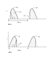
FIG. 4 shows acontrol signal 122 produced by thecontroller 108 in accordance with an embodiment of the present invention. Thecontrol signal 122 inFIG. 3 is derived from a rectified half period of a current alternating at a frequency f, e.g. 50 Hz or 60 Hz. The amplitude of thecontrol signal 122 is the drive voltage V of thesolenoid pump 106. Thecontroller 108 is arranged to forward a phase-angled part of this half-phase to thesolenoid 220 of thesolenoid pump 106. The phase angle θ effectively defines thearea 412 under thecontrol signal 122. The size of thearea 412 is correlated to the amount of energy to be stored in thespring 210. Variation of the phase angle θ thus varies the amount of energy to be stored in thespring 210 of thesolenoid pump 106, or, in other words, the location of theintermediate position 235 in thechamber 212. Thearea 414 indicates the part of the half period of the alternating current that is excluded from thecontrol signal 122. The periods of thecontrol signal 122 are separated in time by adistance 1/f, i.e. occur in each phase cycle of the alternating current. - The phase angle θ may be dynamically adjusted by the
controller 108, e.g. in response to afeedback signal 124 from theflow meter 110, indicating a discrepancy between an intended fluid flow rate and an actual fluid flow rate, or in response to a change in user requirements. Other embodiments for dynamically adjusting this phase angle will be apparent to the skilled person. - It will be appreciated that the shape of the
control signal 122 inFIG. 4 is shown by way of non-limiting example only. Other shapes are equally feasible. For instance, as shown inFIG. 5 , thearea 414 excluded from thecontrol signal 122 may be located at the end of the half phase of the alternating current instead of at its beginning. Alternatively, thecontrol signal 122 does not have to be derived from an alternating current, and does not need to have a truncated sinusoidal shape. Other wave forms, e.g. square waves, are equally feasible. - It should be noted that the above-mentioned embodiments illustrate rather than limit the invention, and that those skilled in the art will be able to design many alternative embodiments without departing from the scope of the appended claims. In the claims, any reference signs placed between parentheses shall not be construed as limiting the claim. The word "comprising" does not exclude the presence of elements or steps other than those listed in a claim. The word "a" or "an" preceding an element does not exclude the presence of a plurality of such elements. The invention can be implemented by means of hardware comprising several distinct elements. In the device claim enumerating several means, several of these means can be embodied by one and the same item of hardware. The mere fact that certain measures are recited in mutually different dependent claims does not indicate that a combination of these measures cannot be used to advantage.
Claims (15)
- A beverage dispensing apparatus (100), comprising:a solenoid pump (106) coupled between a fluid inlet (102) and a fluid outlet (104) for pumping the fluid from said inlet to said outlet, said pump comprising a spring-loaded linear pumping member (206) axially displaceable between a spring-loaded position (240) and a spring-released end position (230); anda controller (108) for the solenoid pump (106), said controller being arranged to energize the pumping member (206) into an intermediate position (235) between the spring-released end position (230) and the spring-loaded position (240).
- An apparatus (100) according to claim 1, wherein the controller (108) is responsive to an alternating current, and arranged to provide the solenoid pump (106) with an energizing signal (122) substantially in each period of the alternating current.
- An apparatus (100) according to claim 2, wherein the controller (108) is arranged to set the amount of energy of the energizing signal (122) in response to a fluid flow rate indication signal (124).
- An apparatus (100) according to claim 3, wherein the energizing signal (122) is a phase-angled sinusoidal signal, with the amount of energy being defined by the phase-angle (θ).
- An apparatus (100) according to claim 4, wherein the phase-angled sinusoidal signal is a phase-angled part of a rectified half-period of the alternating current.
- An apparatus (100) according to any of claims 3-5, wherein the apparatus further comprises a flow meter (110) for producing the fluid flow rate indication signal (124), the controller (108) being arranged to adjust the energizing signal (122) based on a discrepancy between the fluid flow rate indication signal (124) and a required fluid flow rate.
- An apparatus (100) according to claim 6, wherein the flow meter (110) comprises a paddle wheel.
- An apparatus (100) according to claims 6 or 7, wherein the required flowrate is user-defined.
- An apparatus (100) according to any of the preceding claims, further comprising a fluid temperature adjustment stage (112) between the fluid inlet (102) and the fluid outlet (104).
- An apparatus (100) according to claim 9, wherein the fluid temperature adjustment stage (112) comprises a heating stage, the apparatus further comprising a holder (118) between the heating stage and the fluid outlet (104) for receiving a beverage brewing product.
- An apparatus (100) according to any of the preceding claims, further comprising a signal processor (120), wherein the controller (108) is implemented in software on the signal processor.
- A method of controlling a solenoid pump (106) for pumping a fluid from a fluid inlet (102) to a fluid outlet (104) of a beverage dispensing apparatus (100), said pump comprising a spring-loaded linear pumping member (206) axially displaceable between a spring-loaded position (240) and a spring-released end position (230), the method comprising energizing the pumping member (206) into an intermediate position (235) between the spring-released end position (230) and the spring-loaded position (240).
- A method according to claim 12, wherein said displacement step comprises providing the solenoid pump (106) with an energizing signal (122) substantially in each period of an alternating current.
- A method according to claim 13, wherein the step of providing the energizing signal (122) comprises providing a phase-angled sinusoidal signal, with the amount of energy being defined by the phase-angle (θ).
- A method according to claim 13 or 14, further comprising adjusting the energizing signal (122) based on a discrepancy between a fluid flow rate indication signal (124) and a required fluid flow rate.
Priority Applications (11)
| Application Number | Priority Date | Filing Date | Title |
|---|---|---|---|
| ES08153916T ES2376678T3 (en) | 2008-04-01 | 2008-04-01 | APPLIANCE FOR THE DISPENSATION OF DRINKS THAT INCLUDES A SOLENOID PUMP AND METHOD FOR THE CONTROL OF THE SOLENOID PUMP. |
| PT08153916T PT2107242E (en) | 2008-04-01 | 2008-04-01 | Beverage dispensing apparatus comprising a solenoid pump and method of controlling the solenoid pump |
| PL08153916T PL2107242T3 (en) | 2008-04-01 | 2008-04-01 | Beverage dispensing apparatus comprising a solenoid pump and method of controlling the solenoid pump |
| AT08153916T ATE539261T1 (en) | 2008-04-01 | 2008-04-01 | BEVERAGE DISPENSER COMPRISING AN ELECTROMAGNETICALLY DRIVEN PUMP AND METHOD FOR CONTROLLING THE PUMP |
| EP08153916A EP2107242B1 (en) | 2008-04-01 | 2008-04-01 | Beverage dispensing apparatus comprising a solenoid pump and method of controlling the solenoid pump |
| DK08153916.5T DK2107242T3 (en) | 2008-04-01 | 2008-04-01 | A beverage dispensing apparatus comprising a magnetic pump and method for controlling the magnetic pump |
| JP2009064492A JP5495590B2 (en) | 2008-04-01 | 2009-03-17 | Beverage dispensing apparatus and method |
| CA002659130A CA2659130A1 (en) | 2008-04-01 | 2009-03-19 | Beverage dispensing apparatus and method |
| US12/411,862 US20090242584A1 (en) | 2008-04-01 | 2009-03-26 | Beverage dispensing apparatus and method |
| CN2009101302900A CN101554986B (en) | 2008-04-01 | 2009-04-01 | Beverage dispensing apparatus and method |
| HK10103242.8A HK1136331A1 (en) | 2008-04-01 | 2010-03-29 | Beverage dispensing apparatus comprising a solenoid pump and method of controlling the solenoid pump |
Applications Claiming Priority (1)
| Application Number | Priority Date | Filing Date | Title |
|---|---|---|---|
| EP08153916A EP2107242B1 (en) | 2008-04-01 | 2008-04-01 | Beverage dispensing apparatus comprising a solenoid pump and method of controlling the solenoid pump |
Publications (2)
| Publication Number | Publication Date |
|---|---|
| EP2107242A1 true EP2107242A1 (en) | 2009-10-07 |
| EP2107242B1 EP2107242B1 (en) | 2011-12-28 |
Family
ID=39832256
Family Applications (1)
| Application Number | Title | Priority Date | Filing Date |
|---|---|---|---|
| EP08153916A Revoked EP2107242B1 (en) | 2008-04-01 | 2008-04-01 | Beverage dispensing apparatus comprising a solenoid pump and method of controlling the solenoid pump |
Country Status (11)
| Country | Link |
|---|---|
| US (1) | US20090242584A1 (en) |
| EP (1) | EP2107242B1 (en) |
| JP (1) | JP5495590B2 (en) |
| CN (1) | CN101554986B (en) |
| AT (1) | ATE539261T1 (en) |
| CA (1) | CA2659130A1 (en) |
| DK (1) | DK2107242T3 (en) |
| ES (1) | ES2376678T3 (en) |
| HK (1) | HK1136331A1 (en) |
| PL (1) | PL2107242T3 (en) |
| PT (1) | PT2107242E (en) |
Cited By (5)
| Publication number | Priority date | Publication date | Assignee | Title |
|---|---|---|---|---|
| CN102506950A (en) * | 2011-11-07 | 2012-06-20 | 中国科学院自动化研究所 | Device for detecting free flow and back pressure flow of electromagnetic pump and detection method |
| EP3028610A1 (en) | 2014-12-01 | 2016-06-08 | Nestec S.A. | Beverage preparation device with pump and method for controlling the pump |
| WO2017005618A1 (en) * | 2015-07-03 | 2017-01-12 | Nestec S.A. | Control system for pump of beverage preparation machine |
| FR3075273A1 (en) * | 2017-12-19 | 2019-06-21 | Continental Automotive France | METHOD FOR MANAGING A PISTON PUMP FOR A HEAT ENGINE |
| WO2022005294A1 (en) * | 2020-07-03 | 2022-01-06 | Bravilor Bonamat B.V. | A hot beverage brewing apparatus |
Families Citing this family (10)
| Publication number | Priority date | Publication date | Assignee | Title |
|---|---|---|---|---|
| CN103718417B (en) * | 2011-08-16 | 2016-10-12 | 皇家飞利浦有限公司 | Capacitive character contactless power supply system |
| EP2771579B1 (en) * | 2011-10-28 | 2019-08-21 | DEKA Products Limited Partnership | Product dispensing system with pwm controlled solenoid pump |
| RU2653678C2 (en) | 2012-12-21 | 2018-05-11 | Нестек С.А. | Device for producing milk foam |
| EP3590394A1 (en) * | 2014-08-20 | 2020-01-08 | Breville Pty Limited | Coffee maker |
| US10156468B2 (en) * | 2015-10-20 | 2018-12-18 | Sharkninja Operating Llc | Dynamic calibration compensation for flow meter |
| ES1160808Y (en) * | 2016-06-16 | 2016-10-04 | Teylor Intelligent Processes Sl | AUTONOMOUS HYDRAULIC UNIT |
| US11698064B2 (en) * | 2017-12-29 | 2023-07-11 | Koninklijke Philips N.V. | System and method for operating a pump in a humidifier |
| CN109044106A (en) * | 2018-10-15 | 2018-12-21 | 深圳鼎加弘思饮品科技有限公司 | Locked beverage machine is pressed using lever |
| TWI722910B (en) * | 2020-05-26 | 2021-03-21 | 東陞國際科技股份有限公司 | Control method of flow velocity and the brewing machine |
| WO2023232765A1 (en) * | 2022-05-31 | 2023-12-07 | Société des Produits Nestlé S.A. | Fluid flow |
Citations (11)
| Publication number | Priority date | Publication date | Assignee | Title |
|---|---|---|---|---|
| US4086518A (en) * | 1976-07-29 | 1978-04-25 | Facet Enterprises, Inc. | On demand fluid pump |
| US4308475A (en) * | 1978-07-18 | 1981-12-29 | Sundstrand Corporation | Solenoid pump adapted for noiseless operation |
| EP0288216A1 (en) * | 1987-04-15 | 1988-10-26 | Eaton S.A.M. | Electrical fluid pump |
| US5073095A (en) | 1990-04-10 | 1991-12-17 | Purolator Product Company | Whisper quiet electromagnetic fluid pump |
| WO2002061780A1 (en) * | 2001-01-30 | 2002-08-08 | Mc Dermott, Will & Emery | System and method for servo control of nonlinear electromagnetic actuators |
| FR2847708A1 (en) | 2002-11-27 | 2004-05-28 | Invensys S A M | Device for reducing sound level of oscillating piston pump used in e.g. coffee makers, includes additional electric circuit branch mounted in parallel with electromagnetic coil and consisting of rectifying diode and switch mounted in series |
| FR2855223A1 (en) * | 2003-05-22 | 2004-11-26 | Seb Sa | Electromagnetic pump loading state detecting method for e.g. automatic coffee maker, involves detecting loading state when difference between maximum pump current time and reference time approaches value related to pumps vacuum state |
| US6942470B1 (en) | 1998-05-15 | 2005-09-13 | Rolland Versini | Motor pump system with axial through flow utilizing an incorporated flowmeter and pressure controller |
| US20060054614A1 (en) * | 2001-11-02 | 2006-03-16 | Baxter James R | Systems and methods for dispensing product |
| US7168925B2 (en) * | 1998-03-20 | 2007-01-30 | Humphries James C | Automatic optimizing pump and sensor system |
| US20070181004A1 (en) | 2006-02-09 | 2007-08-09 | Robert Hale | Liquid dispensing apparatus |
Family Cites Families (11)
| Publication number | Priority date | Publication date | Assignee | Title |
|---|---|---|---|---|
| FR1472032A (en) * | 1965-03-12 | 1967-03-10 | Reciprocating drive machine with electromagnetic control | |
| JPS6453074A (en) * | 1987-08-22 | 1989-03-01 | Taisan Industrial Co | Driving circuit for electromagnetic pump |
| JPH04179871A (en) * | 1990-11-14 | 1992-06-26 | Fuji Clean Kogyo Kk | Fluid pump |
| JP2553638Y2 (en) * | 1990-11-22 | 1997-11-12 | 株式会社長野計器製作所 | Drive unit for electromagnetic reciprocating pump |
| US6789420B2 (en) * | 2001-10-19 | 2004-09-14 | Ark-Les Corporation | Oil flow sensing |
| US7017472B2 (en) * | 2003-10-10 | 2006-03-28 | Hp Intellectual Corp. | Brewing apparatus water temperature control |
| US7905373B2 (en) * | 2006-03-06 | 2011-03-15 | Deka Products Limited Partnership | System and method for generating a drive signal |
| US7740152B2 (en) * | 2006-03-06 | 2010-06-22 | The Coca-Cola Company | Pump system with calibration curve |
| CN101294556A (en) * | 2007-04-28 | 2008-10-29 | 德昌电机股份有限公司 | Solenoid pump |
| US20090097998A1 (en) * | 2007-10-10 | 2009-04-16 | The Coca-Cola Company | Fixed Displacement Pump |
| US8185237B2 (en) * | 2007-12-28 | 2012-05-22 | Malema Engineering Corporation | Dispense verification meters |
-
2008
- 2008-04-01 PT PT08153916T patent/PT2107242E/en unknown
- 2008-04-01 ES ES08153916T patent/ES2376678T3/en active Active
- 2008-04-01 EP EP08153916A patent/EP2107242B1/en not_active Revoked
- 2008-04-01 PL PL08153916T patent/PL2107242T3/en unknown
- 2008-04-01 DK DK08153916.5T patent/DK2107242T3/en active
- 2008-04-01 AT AT08153916T patent/ATE539261T1/en active
-
2009
- 2009-03-17 JP JP2009064492A patent/JP5495590B2/en not_active Expired - Fee Related
- 2009-03-19 CA CA002659130A patent/CA2659130A1/en not_active Abandoned
- 2009-03-26 US US12/411,862 patent/US20090242584A1/en not_active Abandoned
- 2009-04-01 CN CN2009101302900A patent/CN101554986B/en not_active Expired - Fee Related
-
2010
- 2010-03-29 HK HK10103242.8A patent/HK1136331A1/en not_active IP Right Cessation
Patent Citations (11)
| Publication number | Priority date | Publication date | Assignee | Title |
|---|---|---|---|---|
| US4086518A (en) * | 1976-07-29 | 1978-04-25 | Facet Enterprises, Inc. | On demand fluid pump |
| US4308475A (en) * | 1978-07-18 | 1981-12-29 | Sundstrand Corporation | Solenoid pump adapted for noiseless operation |
| EP0288216A1 (en) * | 1987-04-15 | 1988-10-26 | Eaton S.A.M. | Electrical fluid pump |
| US5073095A (en) | 1990-04-10 | 1991-12-17 | Purolator Product Company | Whisper quiet electromagnetic fluid pump |
| US7168925B2 (en) * | 1998-03-20 | 2007-01-30 | Humphries James C | Automatic optimizing pump and sensor system |
| US6942470B1 (en) | 1998-05-15 | 2005-09-13 | Rolland Versini | Motor pump system with axial through flow utilizing an incorporated flowmeter and pressure controller |
| WO2002061780A1 (en) * | 2001-01-30 | 2002-08-08 | Mc Dermott, Will & Emery | System and method for servo control of nonlinear electromagnetic actuators |
| US20060054614A1 (en) * | 2001-11-02 | 2006-03-16 | Baxter James R | Systems and methods for dispensing product |
| FR2847708A1 (en) | 2002-11-27 | 2004-05-28 | Invensys S A M | Device for reducing sound level of oscillating piston pump used in e.g. coffee makers, includes additional electric circuit branch mounted in parallel with electromagnetic coil and consisting of rectifying diode and switch mounted in series |
| FR2855223A1 (en) * | 2003-05-22 | 2004-11-26 | Seb Sa | Electromagnetic pump loading state detecting method for e.g. automatic coffee maker, involves detecting loading state when difference between maximum pump current time and reference time approaches value related to pumps vacuum state |
| US20070181004A1 (en) | 2006-02-09 | 2007-08-09 | Robert Hale | Liquid dispensing apparatus |
Cited By (13)
| Publication number | Priority date | Publication date | Assignee | Title |
|---|---|---|---|---|
| CN102506950A (en) * | 2011-11-07 | 2012-06-20 | 中国科学院自动化研究所 | Device for detecting free flow and back pressure flow of electromagnetic pump and detection method |
| CN102506950B (en) * | 2011-11-07 | 2013-06-05 | 中国科学院自动化研究所 | Device for detecting free flow and back pressure flow of electromagnetic pump and detection method |
| EP3028610A1 (en) | 2014-12-01 | 2016-06-08 | Nestec S.A. | Beverage preparation device with pump and method for controlling the pump |
| RU2716912C2 (en) * | 2015-07-03 | 2020-03-17 | Сосьете Де Продюи Нестле С.А. | Beverage preparation device pump control system |
| WO2017005618A1 (en) * | 2015-07-03 | 2017-01-12 | Nestec S.A. | Control system for pump of beverage preparation machine |
| AU2016289397B2 (en) * | 2015-07-03 | 2020-08-13 | Société des Produits Nestlé S.A. | Control system for pump of beverage preparation machine |
| US10959566B2 (en) | 2015-07-03 | 2021-03-30 | Societe Des Produits Nestle S.A. | Control system for pump of beverage preparation machine |
| FR3075273A1 (en) * | 2017-12-19 | 2019-06-21 | Continental Automotive France | METHOD FOR MANAGING A PISTON PUMP FOR A HEAT ENGINE |
| WO2019122590A1 (en) * | 2017-12-19 | 2019-06-27 | Continental Automotive France | Method for managing a piston pump for a heat engine |
| CN111479995A (en) * | 2017-12-19 | 2020-07-31 | 法国大陆汽车公司 | Method for managing a pump with a piston of a heat engine |
| CN111479995B (en) * | 2017-12-19 | 2022-09-30 | 法国大陆汽车公司 | Method for managing a pump with a piston of a heat engine |
| WO2022005294A1 (en) * | 2020-07-03 | 2022-01-06 | Bravilor Bonamat B.V. | A hot beverage brewing apparatus |
| NL2025985B1 (en) * | 2020-07-03 | 2022-03-08 | Bravilor Bonamat B V | A hot beverage brewing apparatus |
Also Published As
| Publication number | Publication date |
|---|---|
| CN101554986A (en) | 2009-10-14 |
| CN101554986B (en) | 2013-08-14 |
| ATE539261T1 (en) | 2012-01-15 |
| JP2010001071A (en) | 2010-01-07 |
| ES2376678T3 (en) | 2012-03-15 |
| CA2659130A1 (en) | 2009-10-01 |
| EP2107242B1 (en) | 2011-12-28 |
| PT2107242E (en) | 2012-02-07 |
| DK2107242T3 (en) | 2012-03-19 |
| PL2107242T3 (en) | 2012-05-31 |
| HK1136331A1 (en) | 2010-06-25 |
| JP5495590B2 (en) | 2014-05-21 |
| US20090242584A1 (en) | 2009-10-01 |
Similar Documents
| Publication | Publication Date | Title |
|---|---|---|
| EP2107242A1 (en) | Beverage dispensing apparatus comprising a solenoid pump and method of controlling the solenoid pump | |
| US8344896B2 (en) | Process for detecting scale formation in a beverage preparation machine | |
| CN108024660B (en) | Brewing device for preparing hot beverages | |
| CN108024661B (en) | Method and apparatus for preparing coffee beverage | |
| CN105979831B (en) | Machine for preparing beverages with a microphone sensor | |
| KR20170063939A (en) | Beverage brewing systems and methods for using the same | |
| CN107536444B (en) | Electric cooker and cooking control method thereof | |
| JP6737783B2 (en) | Beverage preparation device with a pump and method for controlling the pump | |
| EP3700397B1 (en) | Coffee machine | |
| US11641975B2 (en) | Flow system delivery system and beverage machine using same | |
| WO2016051427A1 (en) | Heating device for hot drinks automatic dispensing machines |
Legal Events
| Date | Code | Title | Description |
|---|---|---|---|
| PUAI | Public reference made under article 153(3) epc to a published international application that has entered the european phase |
Free format text: ORIGINAL CODE: 0009012 |
|
| 17P | Request for examination filed |
Effective date: 20080409 |
|
| AK | Designated contracting states |
Kind code of ref document: A1 Designated state(s): AT BE BG CH CY CZ DE DK EE ES FI FR GB GR HR HU IE IS IT LI LT LU LV MC MT NL NO PL PT RO SE SI SK TR |
|
| AX | Request for extension of the european patent |
Extension state: AL BA MK RS |
|
| AKX | Designation fees paid |
Designated state(s): AT BE BG CH CY CZ DE DK EE ES FI FR GB GR HR HU IE IS IT LI LT LU LV MC MT NL NO PL PT RO SE SI SK TR |
|
| REG | Reference to a national code |
Ref country code: HK Ref legal event code: DE Ref document number: 1136331 Country of ref document: HK |
|
| 17Q | First examination report despatched |
Effective date: 20110203 |
|
| GRAP | Despatch of communication of intention to grant a patent |
Free format text: ORIGINAL CODE: EPIDOSNIGR1 |
|
| RIN1 | Information on inventor provided before grant (corrected) |
Inventor name: PALMER, TIMOTHY JOHN |
|
| GRAS | Grant fee paid |
Free format text: ORIGINAL CODE: EPIDOSNIGR3 |
|
| GRAA | (expected) grant |
Free format text: ORIGINAL CODE: 0009210 |
|
| AK | Designated contracting states |
Kind code of ref document: B1 Designated state(s): AT BE BG CH CY CZ DE DK EE ES FI FR GB GR HR HU IE IS IT LI LT LU LV MC MT NL NO PL PT RO SE SI SK TR |
|
| REG | Reference to a national code |
Ref country code: GB Ref legal event code: FG4D |
|
| REG | Reference to a national code |
Ref country code: CH Ref legal event code: EP |
|
| REG | Reference to a national code |
Ref country code: AT Ref legal event code: REF Ref document number: 539261 Country of ref document: AT Kind code of ref document: T Effective date: 20120115 |
|
| REG | Reference to a national code |
Ref country code: IE Ref legal event code: FG4D |
|
| REG | Reference to a national code |
Ref country code: PT Ref legal event code: SC4A Free format text: AVAILABILITY OF NATIONAL TRANSLATION Effective date: 20120126 |
|
| REG | Reference to a national code |
Ref country code: DE Ref legal event code: R096 Ref document number: 602008012291 Country of ref document: DE Effective date: 20120308 |
|
| REG | Reference to a national code |
Ref country code: ES Ref legal event code: FG2A Ref document number: 2376678 Country of ref document: ES Kind code of ref document: T3 Effective date: 20120315 |
|
| REG | Reference to a national code |
Ref country code: DK Ref legal event code: T3 |
|
| REG | Reference to a national code |
Ref country code: SE Ref legal event code: TRGR |
|
| REG | Reference to a national code |
Ref country code: NL Ref legal event code: T3 |
|
| PG25 | Lapsed in a contracting state [announced via postgrant information from national office to epo] |
Ref country code: LT Free format text: LAPSE BECAUSE OF FAILURE TO SUBMIT A TRANSLATION OF THE DESCRIPTION OR TO PAY THE FEE WITHIN THE PRESCRIBED TIME-LIMIT Effective date: 20111228 |
|
| REG | Reference to a national code |
Ref country code: NO Ref legal event code: T2 Effective date: 20111228 |
|
| REG | Reference to a national code |
Ref country code: HK Ref legal event code: GR Ref document number: 1136331 Country of ref document: HK |
|
| LTIE | Lt: invalidation of european patent or patent extension |
Effective date: 20111228 |
|
| REG | Reference to a national code |
Ref country code: GR Ref legal event code: EP Ref document number: 20120400612 Country of ref document: GR Effective date: 20120417 |
|
| PG25 | Lapsed in a contracting state [announced via postgrant information from national office to epo] |
Ref country code: LV Free format text: LAPSE BECAUSE OF FAILURE TO SUBMIT A TRANSLATION OF THE DESCRIPTION OR TO PAY THE FEE WITHIN THE PRESCRIBED TIME-LIMIT Effective date: 20111228 Ref country code: HR Free format text: LAPSE BECAUSE OF FAILURE TO SUBMIT A TRANSLATION OF THE DESCRIPTION OR TO PAY THE FEE WITHIN THE PRESCRIBED TIME-LIMIT Effective date: 20111228 Ref country code: SI Free format text: LAPSE BECAUSE OF FAILURE TO SUBMIT A TRANSLATION OF THE DESCRIPTION OR TO PAY THE FEE WITHIN THE PRESCRIBED TIME-LIMIT Effective date: 20111228 |
|
| REG | Reference to a national code |
Ref country code: PL Ref legal event code: T3 |
|
| PG25 | Lapsed in a contracting state [announced via postgrant information from national office to epo] |
Ref country code: CY Free format text: LAPSE BECAUSE OF FAILURE TO SUBMIT A TRANSLATION OF THE DESCRIPTION OR TO PAY THE FEE WITHIN THE PRESCRIBED TIME-LIMIT Effective date: 20111228 |
|
| PG25 | Lapsed in a contracting state [announced via postgrant information from national office to epo] |
Ref country code: EE Free format text: LAPSE BECAUSE OF FAILURE TO SUBMIT A TRANSLATION OF THE DESCRIPTION OR TO PAY THE FEE WITHIN THE PRESCRIBED TIME-LIMIT Effective date: 20111228 Ref country code: SK Free format text: LAPSE BECAUSE OF FAILURE TO SUBMIT A TRANSLATION OF THE DESCRIPTION OR TO PAY THE FEE WITHIN THE PRESCRIBED TIME-LIMIT Effective date: 20111228 Ref country code: CZ Free format text: LAPSE BECAUSE OF FAILURE TO SUBMIT A TRANSLATION OF THE DESCRIPTION OR TO PAY THE FEE WITHIN THE PRESCRIBED TIME-LIMIT Effective date: 20111228 Ref country code: IS Free format text: LAPSE BECAUSE OF FAILURE TO SUBMIT A TRANSLATION OF THE DESCRIPTION OR TO PAY THE FEE WITHIN THE PRESCRIBED TIME-LIMIT Effective date: 20120428 Ref country code: BG Free format text: LAPSE BECAUSE OF FAILURE TO SUBMIT A TRANSLATION OF THE DESCRIPTION OR TO PAY THE FEE WITHIN THE PRESCRIBED TIME-LIMIT Effective date: 20120328 |
|
| PG25 | Lapsed in a contracting state [announced via postgrant information from national office to epo] |
Ref country code: RO Free format text: LAPSE BECAUSE OF FAILURE TO SUBMIT A TRANSLATION OF THE DESCRIPTION OR TO PAY THE FEE WITHIN THE PRESCRIBED TIME-LIMIT Effective date: 20111228 |
|
| PLBI | Opposition filed |
Free format text: ORIGINAL CODE: 0009260 |
|
| PLBI | Opposition filed |
Free format text: ORIGINAL CODE: 0009260 |
|
| 26 | Opposition filed |
Opponent name: EUGSTER / FRISMAG AG ELECTROHAUSHALTGERAETE Effective date: 20120927 |
|
| 26 | Opposition filed |
Opponent name: EUGSTER / FRISMAG AG ELECTROHAUSHALTGERAETE Effective date: 20120927 Opponent name: BSH BOSCH UND SIEMENS HAUSGERAETE GMBH Effective date: 20120928 |
|
| PLAX | Notice of opposition and request to file observation + time limit sent |
Free format text: ORIGINAL CODE: EPIDOSNOBS2 |
|
| PG25 | Lapsed in a contracting state [announced via postgrant information from national office to epo] |
Ref country code: MC Free format text: LAPSE BECAUSE OF NON-PAYMENT OF DUE FEES Effective date: 20120430 |
|
| REG | Reference to a national code |
Ref country code: DE Ref legal event code: R026 Ref document number: 602008012291 Country of ref document: DE Effective date: 20120927 |
|
| PLAF | Information modified related to communication of a notice of opposition and request to file observations + time limit |
Free format text: ORIGINAL CODE: EPIDOSCOBS2 |
|
| PLBB | Reply of patent proprietor to notice(s) of opposition received |
Free format text: ORIGINAL CODE: EPIDOSNOBS3 |
|
| PG25 | Lapsed in a contracting state [announced via postgrant information from national office to epo] |
Ref country code: FI Free format text: LAPSE BECAUSE OF FAILURE TO SUBMIT A TRANSLATION OF THE DESCRIPTION OR TO PAY THE FEE WITHIN THE PRESCRIBED TIME-LIMIT Effective date: 20111228 |
|
| PG25 | Lapsed in a contracting state [announced via postgrant information from national office to epo] |
Ref country code: MT Free format text: LAPSE BECAUSE OF FAILURE TO SUBMIT A TRANSLATION OF THE DESCRIPTION OR TO PAY THE FEE WITHIN THE PRESCRIBED TIME-LIMIT Effective date: 20111228 |
|
| PG25 | Lapsed in a contracting state [announced via postgrant information from national office to epo] |
Ref country code: TR Free format text: LAPSE BECAUSE OF FAILURE TO SUBMIT A TRANSLATION OF THE DESCRIPTION OR TO PAY THE FEE WITHIN THE PRESCRIBED TIME-LIMIT Effective date: 20111228 |
|
| PG25 | Lapsed in a contracting state [announced via postgrant information from national office to epo] |
Ref country code: LU Free format text: LAPSE BECAUSE OF NON-PAYMENT OF DUE FEES Effective date: 20120401 |
|
| PG25 | Lapsed in a contracting state [announced via postgrant information from national office to epo] |
Ref country code: HU Free format text: LAPSE BECAUSE OF FAILURE TO SUBMIT A TRANSLATION OF THE DESCRIPTION OR TO PAY THE FEE WITHIN THE PRESCRIBED TIME-LIMIT Effective date: 20080401 |
|
| PGFP | Annual fee paid to national office [announced via postgrant information from national office to epo] |
Ref country code: PT Payment date: 20150330 Year of fee payment: 8 |
|
| PGFP | Annual fee paid to national office [announced via postgrant information from national office to epo] |
Ref country code: PL Payment date: 20150213 Year of fee payment: 8 Ref country code: GR Payment date: 20150312 Year of fee payment: 8 |
|
| PGFP | Annual fee paid to national office [announced via postgrant information from national office to epo] |
Ref country code: IE Payment date: 20150409 Year of fee payment: 8 |
|
| REG | Reference to a national code |
Ref country code: DE Ref legal event code: R103 Ref document number: 602008012291 Country of ref document: DE Ref country code: DE Ref legal event code: R064 Ref document number: 602008012291 Country of ref document: DE |
|
| REG | Reference to a national code |
Ref country code: FR Ref legal event code: PLFP Year of fee payment: 9 |
|
| RDAF | Communication despatched that patent is revoked |
Free format text: ORIGINAL CODE: EPIDOSNREV1 |
|
| PGFP | Annual fee paid to national office [announced via postgrant information from national office to epo] |
Ref country code: ES Payment date: 20160311 Year of fee payment: 9 |
|
| PGFP | Annual fee paid to national office [announced via postgrant information from national office to epo] |
Ref country code: FR Payment date: 20160309 Year of fee payment: 9 Ref country code: BE Payment date: 20160224 Year of fee payment: 9 Ref country code: GB Payment date: 20160330 Year of fee payment: 9 |
|
| PGFP | Annual fee paid to national office [announced via postgrant information from national office to epo] |
Ref country code: NL Payment date: 20160411 Year of fee payment: 9 |
|
| RDAG | Patent revoked |
Free format text: ORIGINAL CODE: 0009271 |
|
| STAA | Information on the status of an ep patent application or granted ep patent |
Free format text: STATUS: PATENT REVOKED |
|
| REG | Reference to a national code |
Ref country code: CH Ref legal event code: PLX |
|
| PGFP | Annual fee paid to national office [announced via postgrant information from national office to epo] |
Ref country code: NO Payment date: 20160412 Year of fee payment: 9 Ref country code: CH Payment date: 20160411 Year of fee payment: 9 Ref country code: DE Payment date: 20160330 Year of fee payment: 9 |
|
| 27W | Patent revoked |
Effective date: 20160121 |
|
| GBPR | Gb: patent revoked under art. 102 of the ep convention designating the uk as contracting state |
Effective date: 20160121 |
|
| PGFP | Annual fee paid to national office [announced via postgrant information from national office to epo] |
Ref country code: SE Payment date: 20160412 Year of fee payment: 9 Ref country code: IT Payment date: 20160418 Year of fee payment: 9 Ref country code: DK Payment date: 20160412 Year of fee payment: 9 Ref country code: AT Payment date: 20160330 Year of fee payment: 9 |
|
| PG25 | Lapsed in a contracting state [announced via postgrant information from national office to epo] |
Ref country code: CH Free format text: LAPSE BECAUSE OF THE APPLICANT RENOUNCES Effective date: 20111228 Ref country code: LI Free format text: LAPSE BECAUSE OF THE APPLICANT RENOUNCES Effective date: 20111228 |
|
| REG | Reference to a national code |
Ref country code: AT Ref legal event code: MA03 Ref document number: 539261 Country of ref document: AT Kind code of ref document: T Effective date: 20160221 |
|
| REG | Reference to a national code |
Ref country code: GR Ref legal event code: NF Ref document number: 20120400612 Country of ref document: GR Effective date: 20160906 |
|
| REG | Reference to a national code |
Ref country code: SE Ref legal event code: ECNC |