EP2107218A2 - Schmier- und Rücklaufsystem - Google Patents
Schmier- und Rücklaufsystem Download PDFInfo
- Publication number
- EP2107218A2 EP2107218A2 EP20090250384 EP09250384A EP2107218A2 EP 2107218 A2 EP2107218 A2 EP 2107218A2 EP 20090250384 EP20090250384 EP 20090250384 EP 09250384 A EP09250384 A EP 09250384A EP 2107218 A2 EP2107218 A2 EP 2107218A2
- Authority
- EP
- European Patent Office
- Prior art keywords
- oil
- bearing
- scavenge
- impellor
- chamber
- Prior art date
- Legal status (The legal status is an assumption and is not a legal conclusion. Google has not performed a legal analysis and makes no representation as to the accuracy of the status listed.)
- Granted
Links
Images
Classifications
-
- F—MECHANICAL ENGINEERING; LIGHTING; HEATING; WEAPONS; BLASTING
- F01—MACHINES OR ENGINES IN GENERAL; ENGINE PLANTS IN GENERAL; STEAM ENGINES
- F01D—NON-POSITIVE DISPLACEMENT MACHINES OR ENGINES, e.g. STEAM TURBINES
- F01D25/00—Component parts, details, or accessories, not provided for in, or of interest apart from, other groups
- F01D25/18—Lubricating arrangements
- F01D25/20—Lubricating arrangements using lubrication pumps
-
- F—MECHANICAL ENGINEERING; LIGHTING; HEATING; WEAPONS; BLASTING
- F01—MACHINES OR ENGINES IN GENERAL; ENGINE PLANTS IN GENERAL; STEAM ENGINES
- F01D—NON-POSITIVE DISPLACEMENT MACHINES OR ENGINES, e.g. STEAM TURBINES
- F01D25/00—Component parts, details, or accessories, not provided for in, or of interest apart from, other groups
- F01D25/18—Lubricating arrangements
-
- F—MECHANICAL ENGINEERING; LIGHTING; HEATING; WEAPONS; BLASTING
- F01—MACHINES OR ENGINES IN GENERAL; ENGINE PLANTS IN GENERAL; STEAM ENGINES
- F01M—LUBRICATING OF MACHINES OR ENGINES IN GENERAL; LUBRICATING INTERNAL COMBUSTION ENGINES; CRANKCASE VENTILATING
- F01M11/00—Component parts, details or accessories, not provided for in, or of interest apart from, groups F01M1/00 - F01M9/00
- F01M11/04—Filling or draining lubricant of or from machines or engines
-
- F—MECHANICAL ENGINEERING; LIGHTING; HEATING; WEAPONS; BLASTING
- F01—MACHINES OR ENGINES IN GENERAL; ENGINE PLANTS IN GENERAL; STEAM ENGINES
- F01M—LUBRICATING OF MACHINES OR ENGINES IN GENERAL; LUBRICATING INTERNAL COMBUSTION ENGINES; CRANKCASE VENTILATING
- F01M11/00—Component parts, details or accessories, not provided for in, or of interest apart from, groups F01M1/00 - F01M9/00
- F01M11/06—Means for keeping lubricant level constant or for accommodating movement or position of machines or engines
-
- F—MECHANICAL ENGINEERING; LIGHTING; HEATING; WEAPONS; BLASTING
- F16—ENGINEERING ELEMENTS AND UNITS; GENERAL MEASURES FOR PRODUCING AND MAINTAINING EFFECTIVE FUNCTIONING OF MACHINES OR INSTALLATIONS; THERMAL INSULATION IN GENERAL
- F16C—SHAFTS; FLEXIBLE SHAFTS; ELEMENTS OR CRANKSHAFT MECHANISMS; ROTARY BODIES OTHER THAN GEARING ELEMENTS; BEARINGS
- F16C33/00—Parts of bearings; Special methods for making bearings or parts thereof
- F16C33/30—Parts of ball or roller bearings
- F16C33/66—Special parts or details in view of lubrication
- F16C33/6637—Special parts or details in view of lubrication with liquid lubricant
- F16C33/6685—Details of collecting or draining, e.g. returning the liquid to a sump
-
- F—MECHANICAL ENGINEERING; LIGHTING; HEATING; WEAPONS; BLASTING
- F16—ENGINEERING ELEMENTS AND UNITS; GENERAL MEASURES FOR PRODUCING AND MAINTAINING EFFECTIVE FUNCTIONING OF MACHINES OR INSTALLATIONS; THERMAL INSULATION IN GENERAL
- F16N—LUBRICATING
- F16N17/00—Lubrication of machines or apparatus working under extreme conditions
-
- F—MECHANICAL ENGINEERING; LIGHTING; HEATING; WEAPONS; BLASTING
- F16—ENGINEERING ELEMENTS AND UNITS; GENERAL MEASURES FOR PRODUCING AND MAINTAINING EFFECTIVE FUNCTIONING OF MACHINES OR INSTALLATIONS; THERMAL INSULATION IN GENERAL
- F16N—LUBRICATING
- F16N31/00—Means for collecting, retaining, or draining-off lubricant in or on machines or apparatus
-
- F—MECHANICAL ENGINEERING; LIGHTING; HEATING; WEAPONS; BLASTING
- F05—INDEXING SCHEMES RELATING TO ENGINES OR PUMPS IN VARIOUS SUBCLASSES OF CLASSES F01-F04
- F05D—INDEXING SCHEME FOR ASPECTS RELATING TO NON-POSITIVE-DISPLACEMENT MACHINES OR ENGINES, GAS-TURBINES OR JET-PROPULSION PLANTS
- F05D2260/00—Function
- F05D2260/60—Fluid transfer
- F05D2260/602—Drainage
-
- F—MECHANICAL ENGINEERING; LIGHTING; HEATING; WEAPONS; BLASTING
- F16—ENGINEERING ELEMENTS AND UNITS; GENERAL MEASURES FOR PRODUCING AND MAINTAINING EFFECTIVE FUNCTIONING OF MACHINES OR INSTALLATIONS; THERMAL INSULATION IN GENERAL
- F16N—LUBRICATING
- F16N31/00—Means for collecting, retaining, or draining-off lubricant in or on machines or apparatus
- F16N31/02—Oil catchers; Oil wipers
- F16N2031/025—Oil-slinger
-
- F—MECHANICAL ENGINEERING; LIGHTING; HEATING; WEAPONS; BLASTING
- F16—ENGINEERING ELEMENTS AND UNITS; GENERAL MEASURES FOR PRODUCING AND MAINTAINING EFFECTIVE FUNCTIONING OF MACHINES OR INSTALLATIONS; THERMAL INSULATION IN GENERAL
- F16N—LUBRICATING
- F16N2210/00—Applications
- F16N2210/02—Turbines
Definitions
- the invention relates to a lubrication and scavenge system.
- it concerns a lubrication and scavenge system for a rolling element bearing arrangement in a gas turbine engine.
- An oil system provides lubrication, cooling and corrosion protection for numerous internal components.
- gas turbine engines employ a self-contained recirculatory oil system that distributes oil form an oil tank under pressure to bearing chambers and other components throughout the engine. Once the oil has performed its immediate function it falls into a collection volume and is returned to the oil tank by scavenge pumps. Gravity plays some part in the collection process and engine designs must ensure avoid, irrespective of engine orientation, spaces which prevent oil being picked-up by the scavenge pumps. In extreme circumstances this can interrupt recirculation of the oil and lead to oil starvation.
- the present invention has for an objection to maintain an oil recirculation path in all circumstances.
- a lubricant scavenge system comprising a scavenge pump, a collection chamber, at least one drainage path leading into the collection chamber, a rotary impellor located in the chamber, at least one off-take passageway in a chamber wall leading from the collection chamber to the scavenge pump, and a shield located between the drainage path and the off-take passageway adjacent a face of the impellor and acting in operation to shield the face of the impellor.
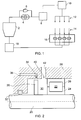
- FIG. 1 there is shown a simplified schematic of a typical oil lubrication and scavenge system for a gas turbine engine is illustrated.
- the system comprises an oil tank or reservoir 2 from which lubrication oil is drawn by a pump indicated at 4.
- the particular system on which the illustration is based is of the pressure relief type in which the pressure of the oil flow to bearing chambers (not shown) is controlled by a pressure relief valve 6.
- the pressurised oil passes through a filter 8 and then a heat exchanger 10 before being distributed to oil supply jets, generally indicated at 12, located in a plurality of bearing chambers, the engine gearbox, etc.
- the oil feed pump 4 is a positive displacement pump that delivers a known flow, proportional to pump speed.
- Oil pressure is generate by resistance to oil flow in the oil supply pipes backed by the bearing chamber pressures.
- the desired flow of oil to a component can be achieved by use of a suitably sized restriction known as an oil jet 12 at the end of the oil line.
- the design of the jet can provide either a ray or a targeted, coherent stream of oil, directed to a component or to a catching feature that will then feed the component.
- Lubrication oil supplied to the bearings etc. is evacuated from bearing chambers and the like and returned to the oil tank 2 by a scavenge system.
- oil is drained from bearing chambers, or wherever it has been utilised, to one or more collection chambers where it is directed into a scavenge-offtake 14 where the oil is picked-up by a scavenge pump 16 and returned to the oil tank 2 through a scavenge filter 18.
- the return path includes a de-aerator to remove entrained air from the oil.
- Oil tank 2 provides a reservoir of oil to supply the oil system.
- the de-aerating device may be incorporated within the oil tank 2 or the return passageway for example adjacent the scavenge filter to remove air from the returning scavenged oil.
- Scavenge pumps 16 generally follow the same construction as the oil feed pump 4. Each bearing chamber is serviced by a dedicated scavenge pump 16 except where bearing chamber pressure or gravity can be used to drive the oil to a shared sump.
- the capacity of a scavenge pump 16 is usually much greater than the oil flow it is required to return to the tank 2, in order to accommodate non-linear flow/speed relationships and aeration of the oil.
- Engines designed to operate for extended periods in zero or negative gravity flight conditions will have oil tanks that incorporate features ensuring a continuous supply of oil.
- FIG. 2 shows a schematic diagram of a bearing chamber and its associated scavenge off take arrangement.
- a supported shaft 20 is journaled in a rolling element bearing indicated generally at 22, the inner race 24 of the bearing is fixed to the shaft 20 and the outer race 26 of the bearing is fixed in a bearing housing 28.
- a small sump region or collection chamber 30 surrounding the shaft 20 is formed between the bearing 22, a shaft seal 32 and bounded by the bearing chamber wall 28 on its radially outer surface.
- Set into the chamber wall 28 is a scavenge off take port 34 and passageway 36 leading to a scavenge pump (not shown).
- Facing scavenge port 34 is a pumping element in the form of a disc 38 carried on the shaft 20. The periphery of disc 38 is aligned with the scavenge port or ports 34 so that centrifugal force arising from rotation of the shaft 20 and disc 38 forces oil contacting the disc into the scavenge port(s) 34.
- Oil may drain into the collection chamber 30 from the bearing 22 and through at least one drainage port 40 in bearing chamber wall 28 at the exit of drainage passages 42 that communicate with spaces (not shown) within a structure surrounding bearing housing 28 in which lubricating oil may accumulate in some or all orientations of the engine.
- the passage or passages 42 are formed to drain the contents of such spaces into a convenient space, such as collection chamber 30 from which the oil may be scavenged.
- the illustrated arrangement has the axis of shaft 20 oriented in a horizontal direction, ie across the page in a left-right direction. This is considered to be a normal orientation for an aircraft propulsion engine in cruise operation.
- a civil aircraft propulsion engine normally spends the majority if not all of its operating life in this orientation with the axis of its main shaft, such as shaft 20, within a few degrees of horizontal.
- the greatest excursion from a substantially horizontal orientation occurs during a climb phase when an engine has a nose-up attitude at a greater angle.
- the capacity of the oil system, in particular the oil tank ensures a sufficient supply of oil.
- certain types of aircraft may be expected to operate at completely different attitudes of nose-up, nose-down or inverted for relatively long periods.
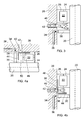
- Figure 3a illustrates the arrangement of Figure 2 rotated counter-clockwise through 90 degrees to a nose-up position.
- the normal draining of oil into the scavenge collection chamber 30 may be interrupted unless special attention is paid to the positioning and layout passages of drainage passages 42 relative to the initial scavenging element, rotary disc 38.
- the oil tank 2 is provided with internal means (not shown) to ensure oil pick-up at all engine orientation so the oil pumping system will continue to operate as normal until the contents of oil tank 2 have been distributed through the oil pump 4. Unless the scavenge system can continue to return oil to oil tank 2 the lubrication system eventually will be starved of supply. Passages such as indicated at 42 must be provided and located with regard to providing drainage paths from enclosed spaces into collection chamber 30 where oil may be recirculated. However, problems may arise in the orientation of Figure 3a because returning oil draining from passage 42 may be forced back through port 40 by windage effects in the collection chamber 30. As a result oil is effectively prevented from draining into the chamber 30 and being recirculated back into the scavenge offtake port 34 and passageway 36.
- FIGS. 4a and 4b The solution provided by the present invention is shown in Figures 4a and 4b comprises a weir, or shield generally indicated at 44, placed between the scavenge port 40 and the scavenge pumping element 38.
- shield 44 The effect of shield 44 is to help establish a flow pattern within collection chamber 30 which effectively guides oil droplets and oil mist onto the scavenge disc 38 at a radial point near to the shaft 20. This is found to be more effective at maintaining an oil film across the surface of the disc 38 which is shed from the periphery of the disc under centrifugal force into the scavenge offtake port 34.
- the shield 44 may comprise a shaped and perforated annular member of sheet metal material thickness.
- the component configuration illustrated has an "L-shaped" cross section consisting of a cylindrical portion 46 that extends in a substantially axial direction parallel to the axis of shaft 20, and an annular portion 48 lying in a substantially radial plane at one end of the cylindrical portion 46.
- the cylindrical portion is formed with a radius matching the radius of the outer surface of the outer race 26 of bearing 22. Exact dimensions depend upon the details of a chosen mounting arrangement.
- cylindrical portion 46 could be trapped between the wall of the bearing housing 28 and the bearing outer race 26, or the housing wall could be at least partly recessed to receive the portion, providing bearing loads can be satisfactorily transferred to the housing wall.
- a number of apertures or slots 50 are formed in the cylindrical portion 46 of the shield member corresponding to the size and spacing of the scavenge intake ports 40 in the bearing chamber wall.
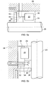
- FIG. 5 A solution is illustrated in Figure 5 in which the outer race 26 of the bearing 22 is extended laterally at 52 to provide a portion functionally equivalent to the shield 44.
- the extension portion 52 of outer bearing race 26 is provided with a number of machined slots 54 spaced apart around the circumference of the bearing race that extend fully through the extended race wall 52 in a substantially radial direction.
- Each slot permits scavenged oil from a drainage passage 42 to enter the collection chamber 30 through ports 40.
- the thickness of the extended race portion 52 ie the dimension in a radial direction, is sufficient to act as an effective shield over the scavenge disc pumping element 38. Scavenged oil is thus passed into collection chamber 30 and towards a more advantageous, radially inner position on the disc 38.
- the arrangement illustrated shows a collection chamber 30 at one side of a bearing 22. It will be understood that a similar arrangement may be provided at the opposite side of the bearing to function in the same manner when the bearing orientation is inverted relative to the orientation illustrated in Figures 4b and 5b , ie rotated through an angle of 180 degrees.
Landscapes
- Engineering & Computer Science (AREA)
- General Engineering & Computer Science (AREA)
- Mechanical Engineering (AREA)
- Rolling Contact Bearings (AREA)
- Centrifugal Separators (AREA)
Applications Claiming Priority (1)
| Application Number | Priority Date | Filing Date | Title |
|---|---|---|---|
| GB0806053A GB2458937A (en) | 2008-04-04 | 2008-04-04 | Lubrication and scavenge system |
Publications (3)
| Publication Number | Publication Date |
|---|---|
| EP2107218A2 true EP2107218A2 (de) | 2009-10-07 |
| EP2107218A3 EP2107218A3 (de) | 2011-03-30 |
| EP2107218B1 EP2107218B1 (de) | 2015-10-14 |
Family
ID=39433051
Family Applications (1)
| Application Number | Title | Priority Date | Filing Date |
|---|---|---|---|
| EP09250384.6A Active EP2107218B1 (de) | 2008-04-04 | 2009-02-13 | Schmier- und Rücklaufsystem |
Country Status (3)
| Country | Link |
|---|---|
| US (1) | US8235176B2 (de) |
| EP (1) | EP2107218B1 (de) |
| GB (1) | GB2458937A (de) |
Cited By (2)
| Publication number | Priority date | Publication date | Assignee | Title |
|---|---|---|---|---|
| WO2010112864A3 (en) * | 2009-04-02 | 2011-06-23 | Cummins Turbo Technologies Limited | A rotating machine with shaft sealing arrangement |
| FR3074848A1 (fr) * | 2017-12-08 | 2019-06-14 | Safran Aircraft Engines | Circuit de lubrification, notamment dans un moteur d'aeronef |
Families Citing this family (12)
| Publication number | Priority date | Publication date | Assignee | Title |
|---|---|---|---|---|
| US8356693B2 (en) * | 2007-09-24 | 2013-01-22 | Honeywell International Inc. | Overboard vent valve for use in an aircraft bearing lubrication system |
| GB2458937A (en) * | 2008-04-04 | 2009-10-07 | Rolls Royce Plc | Lubrication and scavenge system |
| WO2012057885A1 (en) * | 2010-10-27 | 2012-05-03 | Dresser-Rand Company | Multiple motor drivers for a hermetically-sealed motor-compressor system |
| CA2895157A1 (en) | 2012-12-14 | 2014-06-19 | General Electric Company | Pressure fed oil drain for gas turbine engine sump |
| US8870699B2 (en) | 2013-03-11 | 2014-10-28 | Pratt & Whitney Canada Corp. | Lubrication oil system for a reduction gearbox |
| DE102014204062A1 (de) * | 2014-03-06 | 2015-09-10 | Aktiebolaget Skf | Schmiersystem für ein Lager sowie Lager mit einem Schmiersystem und Verfahren zum Schmieren eines Lagers |
| US9849411B2 (en) | 2014-05-28 | 2017-12-26 | United Technologies Corporation | Scavenge filter system for a gas turbine engine |
| DE102014227039A1 (de) * | 2014-12-30 | 2016-06-30 | Siemens Aktiengesellschaft | Schmiermittelauffangeinrichtung |
| DE102017106664A1 (de) * | 2017-03-28 | 2018-10-04 | Rolls-Royce Deutschland Ltd & Co Kg | Strahltriebwerk mit einer Kammer |
| US11162421B2 (en) | 2019-10-22 | 2021-11-02 | Pratt & Whitney Canada Corp. | Bearing cavity and method of evacuating oil therefrom |
| CN112067901B (zh) * | 2020-10-13 | 2023-11-28 | 海南电网有限责任公司电力科学研究院 | 一种绝缘纸介电响应测试装置 |
| JP7567519B2 (ja) * | 2021-02-01 | 2024-10-16 | 日本精工株式会社 | 軸受装置及びスピンドル装置 |
Citations (1)
| Publication number | Priority date | Publication date | Assignee | Title |
|---|---|---|---|---|
| GB774197A (en) | 1954-07-01 | 1957-05-08 | Power Jets Res & Dev Ltd | Gas turbine lubrication system |
Family Cites Families (16)
| Publication number | Priority date | Publication date | Assignee | Title |
|---|---|---|---|---|
| US2604188A (en) * | 1949-08-19 | 1952-07-22 | A V Roe Canada Ltd | Oil supply and scavenge system |
| GB677490A (en) * | 1949-08-19 | 1952-08-13 | Lawrence Edgar Marchant | Oil supply and scavenge system |
| DE2736085A1 (de) * | 1976-08-13 | 1978-02-16 | Seiko Seiki Kk | Schmiereinrichtung fuer ein spindellager |
| US4281942A (en) * | 1978-11-13 | 1981-08-04 | General Electric Company | Lubrication system for high speed spline connection and bearing |
| GB2043799B (en) * | 1979-03-05 | 1983-03-16 | Rolls Royce | Draining oil from bearing |
| JPS61181641A (ja) * | 1985-02-06 | 1986-08-14 | Toshiba Mach Co Ltd | 印刷機における高速回転軸受の潤滑油排出方法 |
| US4756664A (en) * | 1985-10-03 | 1988-07-12 | Sundstrand Corporation | Scavenge oil system |
| US4732236A (en) * | 1986-04-16 | 1988-03-22 | Sundstrand Corporation | Dual impeller pump |
| US4858427A (en) * | 1988-08-08 | 1989-08-22 | General Motors Corporation | Secondary oil system for gas turbine engine |
| JPH11166547A (ja) * | 1997-12-02 | 1999-06-22 | Nippon Seiko Kk | 転がり軸受の間座構造 |
| JP4189677B2 (ja) * | 2003-04-15 | 2008-12-03 | 日本精工株式会社 | 軸受装置およびスピンドル装置 |
| GB0414619D0 (en) * | 2004-06-30 | 2004-08-04 | Rolls Royce Plc | A bearing housing |
| JP4867187B2 (ja) * | 2005-03-31 | 2012-02-01 | 株式会社ジェイテクト | 車両用ピニオン軸支持装置 |
| US7334982B2 (en) * | 2005-05-06 | 2008-02-26 | General Electric Company | Apparatus for scavenging lubricating oil |
| GB2440544A (en) * | 2006-08-02 | 2008-02-06 | Rolls Royce Plc | Bearing discharge flow control arrangement |
| GB2458937A (en) * | 2008-04-04 | 2009-10-07 | Rolls Royce Plc | Lubrication and scavenge system |
-
2008
- 2008-04-04 GB GB0806053A patent/GB2458937A/en not_active Withdrawn
-
2009
- 2009-02-13 EP EP09250384.6A patent/EP2107218B1/de active Active
- 2009-02-17 US US12/379,227 patent/US8235176B2/en active Active
Patent Citations (1)
| Publication number | Priority date | Publication date | Assignee | Title |
|---|---|---|---|---|
| GB774197A (en) | 1954-07-01 | 1957-05-08 | Power Jets Res & Dev Ltd | Gas turbine lubrication system |
Cited By (5)
| Publication number | Priority date | Publication date | Assignee | Title |
|---|---|---|---|---|
| WO2010112864A3 (en) * | 2009-04-02 | 2011-06-23 | Cummins Turbo Technologies Limited | A rotating machine with shaft sealing arrangement |
| GB2469101B (en) * | 2009-04-02 | 2015-10-21 | Cummins Turbo Tech Ltd | A rotating machine with shaft sealing arrangement |
| US9194256B2 (en) | 2009-04-02 | 2015-11-24 | Cummins Turbo Technologies Limited | Rotating machine with shaft sealing arrangement |
| FR3074848A1 (fr) * | 2017-12-08 | 2019-06-14 | Safran Aircraft Engines | Circuit de lubrification, notamment dans un moteur d'aeronef |
| US10961880B2 (en) | 2017-12-08 | 2021-03-30 | Safran Aircraft Engines | Lubrication circuit, particularly in an aircraft engine |
Also Published As
| Publication number | Publication date |
|---|---|
| GB2458937A (en) | 2009-10-07 |
| EP2107218A3 (de) | 2011-03-30 |
| GB0806053D0 (en) | 2008-05-14 |
| EP2107218B1 (de) | 2015-10-14 |
| US20090250296A1 (en) | 2009-10-08 |
| US8235176B2 (en) | 2012-08-07 |
Similar Documents
| Publication | Publication Date | Title |
|---|---|---|
| EP2107218B1 (de) | Schmier- und Rücklaufsystem | |
| US9739173B2 (en) | Gas turbine lubrication systems | |
| EP2538055B1 (de) | Entlüfter für einen Ölbypasskanal für ein Turbofantriebwerk mit Getriebe | |
| US10107197B2 (en) | Lubrication system for gas turbine engines | |
| US11428213B2 (en) | Bearing arrangement for a wind turbine and wind turbine | |
| EP2505879B1 (de) | Getriebe mit einem Ölverteiler | |
| US4541784A (en) | Centrifugal lubricating oil pump of an exhaust gas turbocharger | |
| US11248590B2 (en) | Bearing arrangement for a wind turbine and wind turbine | |
| US8961100B2 (en) | Valve for controlling flow of a turbomachine fluid | |
| US12331667B2 (en) | Flow draining enhancement system for engine sump cavities | |
| EP1906037A2 (de) | Kegelrollenlager | |
| US9863418B2 (en) | Pump system | |
| EP2538037B1 (de) | Motorlagergehäuse | |
| US20110073412A1 (en) | Axial fan compact bearing viscous pump | |
| US2934168A (en) | Lubricating and scavenge system for bearing assembly | |
| US12104528B1 (en) | Forced air supply system for engine cavity under negative-G force | |
| US11788433B2 (en) | Lubrication system of aircraft engine | |
| US11365732B1 (en) | High volume pump system | |
| JP5633261B2 (ja) | 潤滑油供給装置付きターボチャージャ | |
| US11493037B1 (en) | Pump system | |
| CN102996218A (zh) | 水冷发动机 | |
| CN114658547A (zh) | 用于润滑包括润滑剂旁通管道的燃气涡轮发动机的部件的系统 |
Legal Events
| Date | Code | Title | Description |
|---|---|---|---|
| PUAI | Public reference made under article 153(3) epc to a published international application that has entered the european phase |
Free format text: ORIGINAL CODE: 0009012 |
|
| AK | Designated contracting states |
Kind code of ref document: A2 Designated state(s): AT BE BG CH CY CZ DE DK EE ES FI FR GB GR HR HU IE IS IT LI LT LU LV MC MK MT NL NO PL PT RO SE SI SK TR |
|
| AX | Request for extension of the european patent |
Extension state: AL BA RS |
|
| PUAL | Search report despatched |
Free format text: ORIGINAL CODE: 0009013 |
|
| AK | Designated contracting states |
Kind code of ref document: A3 Designated state(s): AT BE BG CH CY CZ DE DK EE ES FI FR GB GR HR HU IE IS IT LI LT LU LV MC MK MT NL NO PL PT RO SE SI SK TR |
|
| AX | Request for extension of the european patent |
Extension state: AL BA RS |
|
| RIC1 | Information provided on ipc code assigned before grant |
Ipc: F16C 33/66 20060101ALI20110222BHEP Ipc: F01D 25/18 20060101AFI20090331BHEP Ipc: F16N 31/00 20060101ALI20110222BHEP |
|
| 17P | Request for examination filed |
Effective date: 20110920 |
|
| AKX | Designation fees paid |
Designated state(s): DE ES FR GB IT |
|
| 17Q | First examination report despatched |
Effective date: 20141016 |
|
| GRAP | Despatch of communication of intention to grant a patent |
Free format text: ORIGINAL CODE: EPIDOSNIGR1 |
|
| INTG | Intention to grant announced |
Effective date: 20150414 |
|
| GRAJ | Information related to disapproval of communication of intention to grant by the applicant or resumption of examination proceedings by the epo deleted |
Free format text: ORIGINAL CODE: EPIDOSDIGR1 |
|
| GRAP | Despatch of communication of intention to grant a patent |
Free format text: ORIGINAL CODE: EPIDOSNIGR1 |
|
| RAP1 | Party data changed (applicant data changed or rights of an application transferred) |
Owner name: ROLLS-ROYCE PLC |
|
| INTG | Intention to grant announced |
Effective date: 20150707 |
|
| GRAS | Grant fee paid |
Free format text: ORIGINAL CODE: EPIDOSNIGR3 |
|
| GRAA | (expected) grant |
Free format text: ORIGINAL CODE: 0009210 |
|
| AK | Designated contracting states |
Kind code of ref document: B1 Designated state(s): DE ES FR GB IT |
|
| REG | Reference to a national code |
Ref country code: GB Ref legal event code: FG4D |
|
| REG | Reference to a national code |
Ref country code: DE Ref legal event code: R096 Ref document number: 602009034193 Country of ref document: DE |
|
| REG | Reference to a national code |
Ref country code: FR Ref legal event code: PLFP Year of fee payment: 8 |
|
| PG25 | Lapsed in a contracting state [announced via postgrant information from national office to epo] |
Ref country code: IT Free format text: LAPSE BECAUSE OF FAILURE TO SUBMIT A TRANSLATION OF THE DESCRIPTION OR TO PAY THE FEE WITHIN THE PRESCRIBED TIME-LIMIT Effective date: 20151014 Ref country code: ES Free format text: LAPSE BECAUSE OF FAILURE TO SUBMIT A TRANSLATION OF THE DESCRIPTION OR TO PAY THE FEE WITHIN THE PRESCRIBED TIME-LIMIT Effective date: 20151014 |
|
| REG | Reference to a national code |
Ref country code: DE Ref legal event code: R082 Ref document number: 602009034193 Country of ref document: DE Representative=s name: HERNANDEZ, YORCK, DIPL.-ING., DE |
|
| REG | Reference to a national code |
Ref country code: DE Ref legal event code: R097 Ref document number: 602009034193 Country of ref document: DE |
|
| PLBE | No opposition filed within time limit |
Free format text: ORIGINAL CODE: 0009261 |
|
| 26N | No opposition filed |
Effective date: 20160715 |
|
| REG | Reference to a national code |
Ref country code: FR Ref legal event code: PLFP Year of fee payment: 9 |
|
| REG | Reference to a national code |
Ref country code: FR Ref legal event code: PLFP Year of fee payment: 10 |
|
| P01 | Opt-out of the competence of the unified patent court (upc) registered |
Effective date: 20230528 |
|
| PGFP | Annual fee paid to national office [announced via postgrant information from national office to epo] |
Ref country code: DE Payment date: 20240228 Year of fee payment: 16 |
|
| PGFP | Annual fee paid to national office [announced via postgrant information from national office to epo] |
Ref country code: FR Payment date: 20250224 Year of fee payment: 17 |
|
| PGFP | Annual fee paid to national office [announced via postgrant information from national office to epo] |
Ref country code: GB Payment date: 20250218 Year of fee payment: 17 |
|
| REG | Reference to a national code |
Ref country code: DE Ref legal event code: R119 Ref document number: 602009034193 Country of ref document: DE |