EP2107007A2 - Seal retainer for use in liquid-storage containers - Google Patents
Seal retainer for use in liquid-storage containers Download PDFInfo
- Publication number
- EP2107007A2 EP2107007A2 EP09009091A EP09009091A EP2107007A2 EP 2107007 A2 EP2107007 A2 EP 2107007A2 EP 09009091 A EP09009091 A EP 09009091A EP 09009091 A EP09009091 A EP 09009091A EP 2107007 A2 EP2107007 A2 EP 2107007A2
- Authority
- EP
- European Patent Office
- Prior art keywords
- seal
- spout
- container
- retention
- rib
- Prior art date
- Legal status (The legal status is an assumption and is not a legal conclusion. Google has not performed a legal analysis and makes no representation as to the accuracy of the status listed.)
- Granted
Links
Images


Classifications
-
- B—PERFORMING OPERATIONS; TRANSPORTING
- B65—CONVEYING; PACKING; STORING; HANDLING THIN OR FILAMENTARY MATERIAL
- B65D—CONTAINERS FOR STORAGE OR TRANSPORT OF ARTICLES OR MATERIALS, e.g. BAGS, BARRELS, BOTTLES, BOXES, CANS, CARTONS, CRATES, DRUMS, JARS, TANKS, HOPPERS, FORWARDING CONTAINERS; ACCESSORIES, CLOSURES, OR FITTINGS THEREFOR; PACKAGING ELEMENTS; PACKAGES
- B65D25/00—Details of other kinds or types of rigid or semi-rigid containers
- B65D25/38—Devices for discharging contents
- B65D25/40—Nozzles or spouts
- B65D25/42—Integral or attached nozzles or spouts
-
- B—PERFORMING OPERATIONS; TRANSPORTING
- B65—CONVEYING; PACKING; STORING; HANDLING THIN OR FILAMENTARY MATERIAL
- B65D—CONTAINERS FOR STORAGE OR TRANSPORT OF ARTICLES OR MATERIALS, e.g. BAGS, BARRELS, BOTTLES, BOXES, CANS, CARTONS, CRATES, DRUMS, JARS, TANKS, HOPPERS, FORWARDING CONTAINERS; ACCESSORIES, CLOSURES, OR FITTINGS THEREFOR; PACKAGING ELEMENTS; PACKAGES
- B65D47/00—Closures with filling and discharging, or with discharging, devices
- B65D47/04—Closures with discharging devices other than pumps
- B65D47/06—Closures with discharging devices other than pumps with pouring spouts or tubes; with discharge nozzles or passages
- B65D47/12—Closures with discharging devices other than pumps with pouring spouts or tubes; with discharge nozzles or passages having removable closures
- B65D47/122—Threaded caps
- B65D47/123—Threaded caps with internal parts
Definitions
- the present invention relates in general to the sealing of an interface between two or more members, such as between a container body and a container spout. More specifically, but not exclusively, the present invention concerns sealing mechanisms, structures, and techniques to be used in combination with liquid-storage containers which may be used to store (and dispense) various liquid substances such as paint, household cleaners, laundry products, and beverages, to name a few.
- Liquid storage containers have been used to store and dispense a wide variety of liquids. While the use of a pouring spout as part of a liquid-storage container is now commonly used for liquid laundry detergents and fabric softeners, only recently have these types of containers been adapted to other liquid-product containers, in particular paint containers.
- Typical metal paint cans include a generally cylindrical can body with a circular upper opening surrounded by a generally U-shaped peripheral channel which captures the outer peripheral lip or protrusion of a circular lid.
- a wire-like metal handle is provided and hinged at opposite ends to the paint can body.
- a further consideration for a suitable paint container is the overall shape and balance, not only for handling and transporting convenience, including the possibility of stacking, but also for the practical consideration of being able to tint to a particular color by adding pigment to a base color, such as white.
- This tinting requires access to the interior of the paint container body and also requires some type of vibratory shaking of the paint container. This in turn focuses some attention on the design in terms of the size and shape of the container as well as the design of the sealing mechanisms which are employed as part of the paint container at those interfaces where leakage could conceivably occur.
- an o-ring seal or gasket is used to seal between the spout and the container.
- the seal is rolled up around a frustum-shaped sidewall of the spout that extends within the container so that the seal is positioned at the lip of the container.
- the seal rolls up the frustum-shaped wall, the seal stretches and twists, which in turn pre-loads the seal.
- the seal is biased to roll back down towards the narrower part of the wall, away from the lip of the container. With the seal out of position, leakage between the spout and the container can occur, which can be extremely undesirable with liquids like paint.
- One aspect of the present invention concerns a spout for a container that includes a retention ridge and an angled retention surface that biases a seal to the proper position for forming a seal between the spout and the container.
- Another aspect concerns a container that includes means for biasing a seal to the proper position between the spout and the container.
- Still yet another aspect concerns a technique for assembling a container in which the retention surface is used to position the seal into the proper position.
- FIGS. 1, 2 and 3 A spout 30 according to one embodiment, among others, of the present invention is illustrated in FIGS. 1, 2 and 3 .
- the spout 30 has a pouring lip 32 with a spout opening 35 from where liquid is poured.
- the spout 30 Around the spout opening 35, the spout 30 has a sidewall 38 and a retention flange 39 that extends radially outwards from the sidewall 38.
- the spout 30 is made of plastic, but it should be appreciated that the spout 30 can be made of other types of materials.
- the spout 30 has an overall annular shape. However, it is contemplated that the spout 30 in other embodiments can have a different overall shape.
- the sidewall 38 of the spout 30 has a frustoconical shape. That is, the sidewall 38 generally tapers away from the retention flange 39 such that the outer diameter of the sidewall 38 generally becomes smaller as it extends farther away from the retention flange 39.
- the sidewall 38 includes a retention surface 43 that tapers from a raised rib 45 towards the retention flange 39. In the illustrated embodiment, the retention surface 43 angles directly from the raised rib 45 to the retention flange 39 so as to bias a seal against the retention flange 45.
- the rib 45 is rounded and continuous in nature. It nevertheless should be appreciated that the rib 45 can be shaped differently in other embodiments.
- the rib 45 in another embodiment can be discontinuous or segmented.
- the sidewall 38 Opposite the retention surface 43, the sidewall 38 has an angled ramp surface 46, which tapers away from the rib 45. From the ramp surface 46, the sidewall 38 has a distal surface 47 that is angled to a lesser extent than the ramp surface 46, and yet still, slightly tapers away from the retention flange 39.
- a lip member 49 extends from the retention flange 39 at a location radially outwards from the sidewall 38.
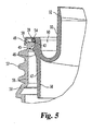
- FIG. 5 illustrates the interface between the spout 30, a container 50, and a spout seal 54 that seals between the container 50 and the spout 30.
- the spout seal 54 in the illustrated embodiment is an o-ring seal, but the spout seal 54 can be shaped differently in other embodiments.
- the spout seal 54 can include a gasket with a rectangular cross-sectional shape or other shapes.
- the container 50 has a neck 56 with external threading 57 for securing a cap to the container 50. As should be realized, the cap can be secured to the container 50 in other manners.
- the spout seal 54 is rolled, or moved in some other manner, up along the sidewall 38 and over the rib 45, which in turn stretches the seal 54 and builds up potential energy. Due to the overall frustum shaped of the sidewall 38, the spout seal 54 would tend to roll out of position were it not for the retention surface 43 and the rib 45.
- the retention surface 43 and the rib 45 on the spout 30 form an undercut portion of the sidewall 38 that is used to secure the spout 30 to the container 50 as well as ensure that the spout seal 54 remains in the proper location for sealing between the container 50 and the spout 30.
- the retention surface 43 is angled or tapers to the retention flange in order to encourage the spout seal 54 to bias against the retention flange 39.
- the neck 56 of the container 50 has an angled rim member 59 that extends radially inwards, around opening 60 the container 50.
- the proper sealing position for the seal 54 is between the rim member 59 of the container 50 and the retention flange 39 of the spout 30.
- the spout 30 and/or the container 50 can be shaped differently in other embodiments to bias the seal 54 so as to form seal at a different location between the container 50 and the spout 30.
- the structure for biasing the seal 54 can be formed on the container 50, on the container 50 in conjunction with the spout 30, on the seal 54, on one or more separate components, or some combination thereof.
- the spout 30 be removed from the container 50 after the container 50 has been filled.
- the spout 30 is removed in order to provide unrestricted access to the container 50.
- the seal 54 With the retention surface 43 and the retention flange 45, the seal 54 remains secured to the spout 30 upon the removal of the spout 30 from the container 50. This reduces the chances that the seal 54 becomes misplaced or even lost. Further, the risk of the seal 54 being damaged by falling on the floor or into paint is reduced.
- the seal 54 is again position in the proper location between the container 50 and the spout 30.
- a cap 63 for enclosing the container 50 which is illustrated and FIG. 6 , is configured to reduce this type of leakage source.
- the cap 63 is generally cylindrical in shape, but it should be recognized that the cap 63 can be shaped differently in other embodiments.
- the cap 63 includes an upper cover portion 66, a outer collar 67 that is configured to secure to the neck 56 of the container 50, and a seal land portion 68 that extends between the cover portion 66 and the collar 67.
- the collar 57 has internal threading 70 that engages the threading 57 on the neck 56 of the container 50, as is depicted in FIG. 7 .
- the seal land 68 has a series of internal seal structures 73 that are rib-shaped for sealing the container 50.
- the seal structures 73 in the illustrated embodiment includes a seal rib or protrusion 75 that is deformable to seal against the retention flange 39 of the spout 30. By sealing against the retention flange 39, the seal rib 75 minimizes leakage between the cap 63 and the spout 30.
- the seal rib 75 in the embodiment shown has a triangular cross-sectional shape such that the seal rib 75 is able to deform, but in other embodiments, the seal rib 75 can be shaped differently.
- the seal land 68 Located radially outward from the seal rib 75, the seal land 68 has a support rib 77 that is configured engage the retention flange 39 near the seal 54 such that the seal 54 is compressed between the spout 30 and the container 50.
- the support rib 77 has a trapezoidal shape with a flat surface to firmly press against the retention flange 39.
- the support rib 77 is slightly shorter than the seal rib 75 so that the seal rib 75 is able to seal against the retention flange 39.
- the support rib 77 can have a different shape in other embodiments.
- a biasing member or rib 79 is positioned radially outwards from both the seal rib 75 and the support rib 77.
- the biasing rib 79 has a trapezoidal cross-sectional shape, but it is contemplated that the biasing rib 79 can have a different shape.
- the biasing rib 79 in FIG. 6 is longer than the support rib 77 so that the biasing rib 79 is able to bend the retention flange 39 on the spout 30 when the cap 63 is secured to the container 50.
- FIG. 7 illustrates the sealing interface when the cap 63 is secured.
- the biasing rib 79 bends the retention flange 39 toward the rim member 59.
- the retention flange 39 is generally thinner than the rest of the spout 30 and made of deformable material, like plastic, so that the biasing rib 79 is able to bend the retention flange 39 at the lip 49.
- the seal 54 is compressed and biased in a radially inwards manner towards the inside of the container 50.
- the seal rib 75 along with the other seal structures 73 form the seal between the cap 63 and the spout 30.
- the rim member 59 can be bent or skewed so that the seal 54 is biased outwardly when the spout 30 is attached. Even when the rim member 59 is skewed, the bending of the retention flange 39 by the biasing rib 79 causes the seal 54 to remain inwardly biased. With both the biasing rib 79 on the cap 63 and the retention surface 43 on the spout 30, seal 54 remains seated at the interface between the retention surface 43 and the retention flange 39.
- the support rib 77 is positioned over the seal 54 so as to create a compressive force between the retention flange 39 and the rim member 54.
- the support rib 77 can be eliminated such that the biasing rib 79 mainly applies the compressive force to the seal 54. With the cap 63 secured to the container 50 in such a manner, the risk of fluid leakage from the container 50 is reduced.
- the unique structure of the spout 30 as well as the unique technique for assembling the spout 30 with the container 50 helps to ensure that the spout seal is properly located so that leakage from the container 50 is minimized.
- the spout 30, the container 50 and/or the cap 63 can be shaped differently in other embodiments.
- the shape of the sidewall 38 at surface 47 can be straight or even in part outwardly flared. Even when shaped in such a manner, the seal 54 can still tend to be biased away from the correct seal location, and consequently, the above-discussed seal biasing mechanism, or some equivalent, still needs to be implemented.
- features from the present invention can be used in different types of containers than those discussed above.
Abstract
Description
- The present application claims the benefit of
U.S. Provisional Patent Application No. 60/628,046, filed November 15, 2004 - The present invention relates in general to the sealing of an interface between two or more members, such as between a container body and a container spout. More specifically, but not exclusively, the present invention concerns sealing mechanisms, structures, and techniques to be used in combination with liquid-storage containers which may be used to store (and dispense) various liquid substances such as paint, household cleaners, laundry products, and beverages, to name a few.
- Liquid storage containers have been used to store and dispense a wide variety of liquids. While the use of a pouring spout as part of a liquid-storage container is now commonly used for liquid laundry detergents and fabric softeners, only recently have these types of containers been adapted to other liquid-product containers, in particular paint containers. Typical metal paint cans include a generally cylindrical can body with a circular upper opening surrounded by a generally U-shaped peripheral channel which captures the outer peripheral lip or protrusion of a circular lid. A wire-like metal handle is provided and hinged at opposite ends to the paint can body. Anyone who has done any painting using such a paint can is no doubt familiar with the many problems in the sense of wasted and splattered paint. The awkwardness of pouring paint from the can into a tray for a roller is also seen as a drawback with this particular design. Dipping a paintbrush into the can and then using the can edge as a wiping edge also creates a mess and causes paint to be deposited in the annular U-shaped channel. As paint collects in this peripheral channel, resealing the lid becomes particularly messy as the captured paint is pushed out and may either splatter or run down the side of the paint can. Aside from the mess, the current metal paint can design results in wasted paint, not only from what drips, splatters, or runs down the side of the can, but also from not being able to tightly reseal the lid onto the can body. If the lid is not tightly resealed on the can body, the paint can dry out or skim over, causing obvious problems of continued use and often resulting in the leftover portion of paint being discarded.
- By designing a paint container with a screw-on lid and a pouring spout with an excess paint drain-back feature, a number of the disadvantages with metal paint cans and the use of such cans can be eliminated. While plastic containers with spouts are now in use for laundry products, there are a number of reasons why such containers are not suitable for paint and why significant design changes must be invented to be able to create a suitable paint container with these structural features. For example, the size of the opening in the container body needs to be expanded for a paint container as compared to a liquid laundry detergent and, as such, the spout design must change. As this occurs, the sealing mechanisms or structures have to be considered. There is a desire to have a wiping edge for the paintbrush as part of a suitable paint container, a factor which is not a consideration with a liquid laundry detergent. The attempt to incorporate this type of wiping edge as part of the pouring spout presents additional design challenges. The drain-back feature is also an important part of any new and improved paint container. Any paint which is wiped off the brush or drips from the brush and any paint which might run down the lip of the pouring spout needs to have a path to reenter the body of the paint container.
- A further consideration for a suitable paint container is the overall shape and balance, not only for handling and transporting convenience, including the possibility of stacking, but also for the practical consideration of being able to tint to a particular color by adding pigment to a base color, such as white. This tinting requires access to the interior of the paint container body and also requires some type of vibratory shaking of the paint container. This in turn focuses some attention on the design in terms of the size and shape of the container as well as the design of the sealing mechanisms which are employed as part of the paint container at those interfaces where leakage could conceivably occur.
- In developing such containers, the costs and difficulties associated with manufacturing the containers is always a concern. One manufacturing issue relates to the ability to maintain the position of the seal between the container and the spout during assembly. As mentioned before, the seal between the pouring spout and the container must survive a number of drastic conditions, including vibratory shaking. In one type of design, an o-ring seal or gasket is used to seal between the spout and the container. During assembly, the seal is rolled up around a frustum-shaped sidewall of the spout that extends within the container so that the seal is positioned at the lip of the container. As the seal rolls up the frustum-shaped wall, the seal stretches and twists, which in turn pre-loads the seal. As a result, the seal is biased to roll back down towards the narrower part of the wall, away from the lip of the container. With the seal out of position, leakage between the spout and the container can occur, which can be extremely undesirable with liquids like paint.
- Thus, there is a need for improvement in this field.
- One aspect of the present invention concerns a spout for a container that includes a retention ridge and an angled retention surface that biases a seal to the proper position for forming a seal between the spout and the container. Another aspect concerns a container that includes means for biasing a seal to the proper position between the spout and the container. Still yet another aspect concerns a technique for assembling a container in which the retention surface is used to position the seal into the proper position.
- Related objects and advantages of the present invention will be apparent from the following description.
-
-
FIG. 1 is a perspective view of a spout with a seal retainer according to one embodiment of the present invention. -
FIG. 2 is a top plan view of theFIG. 1 spout. -
FIG. 3 is a cross-sectional of theFIG. 1 spout as viewed along line 3-3 ofFIG. 2 . -
FIG. 4 is an enlarged cross-sectional view of theFIG. 1 spout. -
FIG. 5 is a cross-sectional view of the sealing interface between theFIG. 1 spout and a container. -
FIG. 6 is a partial cross-sectional view of a cap that encloses theFIG. 1 spout and the container. -
FIG. 7 is a cross-sectional view of theFIG. 5 sealing interface enclosed by theFIG. 6 cap. - For the purpose of promoting an understanding of the principles of the invention, reference will now be made to the embodiments illustrated in the drawings and specific language will be used to describe the same. It is understood that the specific language and figures are not intended to limit the scope of the invention only to the illustrated embodiment. It is also understood that alterations or modifications to the invention or further application of the principles of the invention are contemplated as would occur to persons of ordinary skill in the art to which the invention relates. One embodiment of the invention is shown in great detail, although it will be apparent to those skilled in the relevant art that some features that are not relevant to the present invention may not be shown for the sake of clarity as well as brevity.
- One or more embodiments of the present invention will be described below with reference to molded plastic paint containers with a pouring spout, but it should be recognized that features of this invention can be adapted for use with other types of containers and/or liquids. For some background information about the container systems in which the systems and techniques described below can be used, please refer to
U.S. Patent Application No. 10/924,419, which was filed August 24, 2004 U.S. Application Publication No. 2004/0011813 A1 (Application No.10/365,910, filed February 13, 2003 U.S. Application Publication No. 2004/0011812 A1 (Application No.10/199,618 - A
spout 30 according to one embodiment, among others, of the present invention is illustrated inFIGS. 1, 2 and3 . As shown, thespout 30 has apouring lip 32 with a spout opening 35 from where liquid is poured. Around the spout opening 35, thespout 30 has asidewall 38 and aretention flange 39 that extends radially outwards from thesidewall 38. In the illustrated embodiment, thespout 30 is made of plastic, but it should be appreciated that thespout 30 can be made of other types of materials. As can be seen, thespout 30 has an overall annular shape. However, it is contemplated that thespout 30 in other embodiments can have a different overall shape. - Referring now to
FIG. 4 , thesidewall 38 of thespout 30 has a frustoconical shape. That is, thesidewall 38 generally tapers away from theretention flange 39 such that the outer diameter of thesidewall 38 generally becomes smaller as it extends farther away from theretention flange 39. Thesidewall 38 includes aretention surface 43 that tapers from a raisedrib 45 towards theretention flange 39. In the illustrated embodiment, theretention surface 43 angles directly from the raisedrib 45 to theretention flange 39 so as to bias a seal against theretention flange 45. As depicted, therib 45 is rounded and continuous in nature. It nevertheless should be appreciated that therib 45 can be shaped differently in other embodiments. For example, therib 45 in another embodiment can be discontinuous or segmented. Opposite theretention surface 43, thesidewall 38 has an angledramp surface 46, which tapers away from therib 45. From theramp surface 46, thesidewall 38 has adistal surface 47 that is angled to a lesser extent than theramp surface 46, and yet still, slightly tapers away from theretention flange 39. InFIG. 4 , alip member 49 extends from theretention flange 39 at a location radially outwards from thesidewall 38. -
FIG. 5 illustrates the interface between thespout 30, acontainer 50, and aspout seal 54 that seals between thecontainer 50 and thespout 30. During transit and pouring of fluid from thecontainer 50, maintaining a seal between thespout 30 andcontainer 50 is critical to prevent leakage. By having theseal 54 as a separate component, theseal 54 can compensate for most tolerance differences between thespout 30 and thecontainer 50. Thespout seal 54 in the illustrated embodiment is an o-ring seal, but thespout seal 54 can be shaped differently in other embodiments. For instance, thespout seal 54 can include a gasket with a rectangular cross-sectional shape or other shapes. In the embodiment shown, thecontainer 50 has aneck 56 with external threading 57 for securing a cap to thecontainer 50. As should be realized, the cap can be secured to thecontainer 50 in other manners. - During assembly, the
spout seal 54 is rolled, or moved in some other manner, up along thesidewall 38 and over therib 45, which in turn stretches theseal 54 and builds up potential energy. Due to the overall frustum shaped of thesidewall 38, thespout seal 54 would tend to roll out of position were it not for theretention surface 43 and therib 45. Theretention surface 43 and therib 45 on thespout 30 form an undercut portion of thesidewall 38 that is used to secure thespout 30 to thecontainer 50 as well as ensure that thespout seal 54 remains in the proper location for sealing between thecontainer 50 and thespout 30. Theretention surface 43 is angled or tapers to the retention flange in order to encourage thespout seal 54 to bias against theretention flange 39. In the illustrated embodiment, theneck 56 of thecontainer 50 has anangled rim member 59 that extends radially inwards, around opening 60 thecontainer 50. After theseal 54 is installed, thesidewall 38 of thespout 30 is inserted into theopening 60 of thecontainer 50, and therim member 59 of thecontainer 50 snaps over therib 46 on thespout 30, thereby locking thespout 30 to thecontainer 50. The interference fit between thespout 30 and thecontainer 50 along with the angledretention surface 43 presses thespout seal 54 into the proper sealing position between thespout 30 and thecontainer 50. In theFIG. 5 embodiment, the proper sealing position for theseal 54 is between therim member 59 of thecontainer 50 and theretention flange 39 of thespout 30. It, however, should be recognized that thespout 30 and/or thecontainer 50 can be shaped differently in other embodiments to bias theseal 54 so as to form seal at a different location between thecontainer 50 and thespout 30. For instance, in some further embodiments, it is contemplated that the structure for biasing theseal 54 can be formed on thecontainer 50, on thecontainer 50 in conjunction with thespout 30, on theseal 54, on one or more separate components, or some combination thereof. - Sometimes it is necessary that the
spout 30 be removed from thecontainer 50 after thecontainer 50 has been filled. For example, in order to tint or mix paint in thecontainer 50, thespout 30 is removed in order to provide unrestricted access to thecontainer 50. With theretention surface 43 and theretention flange 45, theseal 54 remains secured to thespout 30 upon the removal of thespout 30 from thecontainer 50. This reduces the chances that theseal 54 becomes misplaced or even lost. Further, the risk of theseal 54 being damaged by falling on the floor or into paint is reduced. Once the spout 42 is reinstalled on thecontainer 50, theseal 54 is again position in the proper location between thecontainer 50 and thespout 30. - During shipping or storage, the
container 50 can be sometimes jarred such that thespout 30 separates from thecontainer 50, thereby creating a potential leakage source. Acap 63 for enclosing thecontainer 50, which is illustrated andFIG. 6 , is configured to reduce this type of leakage source. In the illustrated embodiment, thecap 63 is generally cylindrical in shape, but it should be recognized that thecap 63 can be shaped differently in other embodiments. As shown, thecap 63 includes anupper cover portion 66, aouter collar 67 that is configured to secure to theneck 56 of thecontainer 50, and aseal land portion 68 that extends between thecover portion 66 and thecollar 67. Thecollar 57 has internal threading 70 that engages the threading 57 on theneck 56 of thecontainer 50, as is depicted inFIG. 7 . - Looking at
FIG. 6 , theseal land 68 has a series ofinternal seal structures 73 that are rib-shaped for sealing thecontainer 50. Theseal structures 73 in the illustrated embodiment includes a seal rib orprotrusion 75 that is deformable to seal against theretention flange 39 of thespout 30. By sealing against theretention flange 39, theseal rib 75 minimizes leakage between thecap 63 and thespout 30. Theseal rib 75 in the embodiment shown has a triangular cross-sectional shape such that theseal rib 75 is able to deform, but in other embodiments, theseal rib 75 can be shaped differently. Located radially outward from theseal rib 75, theseal land 68 has asupport rib 77 that is configured engage theretention flange 39 near theseal 54 such that theseal 54 is compressed between thespout 30 and thecontainer 50. In theFIG. 6 embodiment, thesupport rib 77 has a trapezoidal shape with a flat surface to firmly press against theretention flange 39. Thesupport rib 77 is slightly shorter than theseal rib 75 so that theseal rib 75 is able to seal against theretention flange 39. As should be appreciated, thesupport rib 77 can have a different shape in other embodiments. Near thelip 49 of thespout 30, a biasing member orrib 79 is positioned radially outwards from both theseal rib 75 and thesupport rib 77. In the illustrated embodiment, the biasingrib 79 has a trapezoidal cross-sectional shape, but it is contemplated that the biasingrib 79 can have a different shape. The biasingrib 79 inFIG. 6 is longer than thesupport rib 77 so that the biasingrib 79 is able to bend theretention flange 39 on thespout 30 when thecap 63 is secured to thecontainer 50. -
FIG. 7 illustrates the sealing interface when thecap 63 is secured. As thecap 63 is tightened onto thecontainer 50, the biasingrib 79 bends theretention flange 39 toward therim member 59. Theretention flange 39 is generally thinner than the rest of thespout 30 and made of deformable material, like plastic, so that the biasingrib 79 is able to bend theretention flange 39 at thelip 49. In doing so, theseal 54 is compressed and biased in a radially inwards manner towards the inside of thecontainer 50. Theseal rib 75 along with theother seal structures 73 form the seal between thecap 63 and thespout 30. Occasionally, during manufacturing, assembly and/or use, therim member 59 can be bent or skewed so that theseal 54 is biased outwardly when thespout 30 is attached. Even when therim member 59 is skewed, the bending of theretention flange 39 by the biasingrib 79 causes theseal 54 to remain inwardly biased. With both the biasingrib 79 on thecap 63 and theretention surface 43 on thespout 30,seal 54 remains seated at the interface between theretention surface 43 and theretention flange 39. Thesupport rib 77 is positioned over theseal 54 so as to create a compressive force between theretention flange 39 and therim member 54. In another form, it is envisioned that thesupport rib 77 can be eliminated such that the biasingrib 79 mainly applies the compressive force to theseal 54. With thecap 63 secured to thecontainer 50 in such a manner, the risk of fluid leakage from thecontainer 50 is reduced. - As should be appreciated, the unique structure of the
spout 30 as well as the unique technique for assembling thespout 30 with thecontainer 50 helps to ensure that the spout seal is properly located so that leakage from thecontainer 50 is minimized. It should be recognized that thespout 30, thecontainer 50 and/or thecap 63 can be shaped differently in other embodiments. As a non-limiting example, it is envisioned that the shape of thesidewall 38 atsurface 47 can be straight or even in part outwardly flared. Even when shaped in such a manner, theseal 54 can still tend to be biased away from the correct seal location, and consequently, the above-discussed seal biasing mechanism, or some equivalent, still needs to be implemented. Additionally, it is contemplated that features from the present invention can be used in different types of containers than those discussed above. - While the invention has been illustrated and described in detail in the drawings and foregoing description, the same is to be considered as illustrative and not restrictive in character, it being understood that only the preferred embodiment has been shown and described and that all changes and modifications that come within the spirit of the invention are desired to be protected.
-
- [01] A container assembly comprising a container adapted to contain a fluid, the container defining a spout opening with a rim surrounding the spout opening; a spout coupled to the spout opening of the container for pouring the fluid from the container, the spout including a retention flange that extends radially outwards from the spout along the rim of the container; a seal sealing between the spout and the container, wherein the seal is separate from both the spout and the container; and wherein the spout includes a retention ridge for retaining the seal during assembly, the retention having a retention surface that tapers radially inwards towards the retention flange for biasing the seal against the retention flange in order to have the seal positioned between the rim of the container and the retention flange of the spout once assembled.
- [02] A container assembly as described in paragraph 1 further comprising a cap secured to the container for enclosing the container, the cap including a bias member that bends the retention flange of the spout to retain the seal in position; optionally wherein either
- (i) the cap includes a seal member that seals against the retention flange of the spout, or
- (ii) the cap includes a support member that compresses the seal between the' retention flange of the spout and the rim of the container.
- [03] A container assembly as described in paragraph 1, wherein the seal includes an o-ring seal; and/or wherein the spout includes a sidewall that extends inside the container from the retention flange, wherein the sidewall has the retention ridge with the retention surface.
- [04] A container assembly as described in paragraph 1, wherein the sidewall tapers from the retention ridge to become smaller the farther away the sidewall extends from the retention ridge, and the retention ridge prevents the seal from rolling off the spout from tapering off the sidewall; and/or wherein: the rim of the container extends radially inwards into the opening of the container; the retention ridge engages the rim of the container to secure the spout to the container; and the seal biases the rim and the retention ridge into engagement.
- [05] A container assembly as described in paragraph 1, further comprising either
- (i) means for retaining the seal during assembly, wherein the means for retaining the seal during assembly includes the retention ridge; or
- (ii) means for containing the fluid, wherein the means for containing the fluid includes the container; means for pouring the fluid, wherein the means for pouring the fluid includes the spout; and means for sealing between the means for containing the fluid and the means for pouring the fluid, wherein the means for sealing includes the seal.
- [06] A container assembly comprising a container to contain a fluid; a spout coupled to the container for pouring the fluid from the container, the spout including a retention flange to retain the spout on the container; a seal disposed between the retention flange and the container; and a cap including a bias member that bends the retention flange to hold the seal in position to seal the container with the spout.
- [07] A container assembly as described in paragraph 6, wherein the spout includes a retention surface that tapers towards to retention flange to bias the seal towards the retention flange; and together the bias member on the cap and the retention surface on the spout hold the seal in the position to seal the container with the spout; optionally wherein the container assembly further comprises: means for biasing the seal towards the retention flange, wherein the means for biasing the seal includes the retention surface.
- [08] A container assembly as described in paragraph 6, wherein the retention flange extends radially outwards from the spout and has a radially outer edge portion; and the bias member contacts and bends the retention flange proximal the outer edge portion to apply force against the seal in a radially inward direction; and/or wherein the cap is secured to the container; and/or wherein the cap includes seal member that contacts the spout to minimize leakage between the cap and the spout; and/or wherein the cap includes a support member that compresses the seal between the retention flange of the spout and the container.
- [09] A container assembly as described in paragraph 6, further comprising means for containing the fluid, wherein the means for containing the fluid includes the container; means for pouring the fluid from the means for containing the fluid, wherein the means for pouring the fluid includes the spout; means for sealing the means for containing the fluid with the means for pouring the fluid, wherein the means for sealing includes the seal; and means for holding the seal in the position to seal the container with the spout, wherein the means for holding the seal includes the cap.
- [10] A method comprising installing a seal onto a spout that has a retention flange and a sidewall with a retention ridge by moving the seal over the retention ridge on the sidewall of the spout to hold the seal in place between the retention flange and the retention ridge to prevent the seal from slipping off the spout; and attaching the spout to a container with a container opening by inserting the sidewall of the spout into container opening with the seal sealing between the spout and the container.
- [11] A method of paragraph 10, further comprising either
- (i) bending the retention flange of the spout to hold the seal in a sealing position by securing a Cap to the container; or
- (ii) filling the container with paint; and wherein said attaching spout occurs after said filling the container.
- [A1] A container assembly, comprising a container to contain a fluid; a spout coupled to the container for pouring the fluid from the container, the spout including a retention flange to retain the spout on the container; a seal disposed between the retention flange and the container; and characterised by a cap including a bias member that bends the retention flange to hold the seal in position to seal the container with the spout.
- [A2] A container assembly as described in paragraph [A1], wherein the spout includes a retention surface that tapers towards the retention flange to bias the seal towards the retention flange; and together the bias member on the cap and the retention surface on the spout hold the seal in the position to seal the container with the spout.
- [A3] A container assembly as described in paragraph [A2], further comprising means for biasing the seal towards the retention flange, wherein the means for biasing the seal includes the retention surface.
- [A4] A container assembly as described in paragraph [A1], wherein the retention flange extends radially outwards from the spout and has a radially outer edge portion; and the bias member contacts and bends the retention flange proximal the outer edge portion to apply force against the seal in a radially inward direction.
- [A5] A container assembly as described in paragraphs [A1] or [A4], wherein the cap is secured to the container.
- [A6] A container assembly as described in any one of paragraphs [A1], [A4] and [A5], wherein the cap includes seal member that contacts the spout to minimize leakage between the cap and the spout.
- [A7] A container assembly as described in paragraph [A1], wherein the cap includes a support member that compresses the seal between the retention flange of the spout and the container.
- [A8] A container assembly as described in paragraph [A1], further comprising; means for containing the fluid, wherein the means for containing the fluid includes the container; means for pouring the fluid from the means for containing the fluid, wherein the means for pouring the fluid includes the spout; means for sealing the means for containing the fluid with the means for pouring the fluid, wherein the means for sealing includes the seal; and means for holding the seal in the position to seal the container with the spout, wherein the means for holding the seal includes the cap.
- [A9] A method, comprising: installing a seal onto a spout that has a retention flange and a sidewall and attaching the spout to a container with a container opening by inserting the sidewall of the spout into the container opening with the seal sealing between the spout and the container; characterised by the sidewall having a retention ridge and the step of installing the seal comprising moving the seal over the retention ridge on the sidewall of the spout to hold the seal in place between the retention flange and the retention ridge to prevent the seal from slipping off the spout.
- [A10] A method described in paragraph [A9], further comprising bending the retention flange of the spout to hold the seal in a sealing position by securing a cap to the container.
- [A11] A method described in paragraph [A9] further comprising filling the container with paint; and wherein said attaching spout occurs after said filling the container.
Claims (11)
- A method, comprising:installing a seal (54) onto a spout (30) that has a retention flange (39) and a sidewall (38) and attaching the spout (30) to a container (50) with a container opening by inserting the sidewall (38) of the spout (30) into the container opening with the seal (54) sealing between the spout (30) and the container (50);characterised by the sidewall (38) having a retention ridge (45) and the step of installing the seal comprising moving the seal (54) over the retention ridge (45) on the sidewall (38) of the spout (30) to hold the seal (54) in place between the retention flange (39) and the retention ridge (45) to prevent the seal (54) from slipping off the spout (30).
- A method according to claim 1, further comprising bending the retention flange (39) of the spout (30) to hold the seal (54) in a sealing position by securing a cap (63) to the container (50).
- A method according to claim 1 or claim 2, further comprising filling the container (50) with paint; and wherein said attaching spout (30) occurs after said filling the container (50).
- A method according to any of the preceding claims, wherein said installing the seal (54) onto the spout (30) includes rolling the seal (54) along the sidewall (38) and over the retention ridge (45) in order to stretch the seal.
- A method according to claim 4, wherein the seal rolls down a retention surface that is angled to bias the seal (54) against the retention flange (39).
- A method according to any of the preceding claims, wherein the seal (54) is an o-ring seal.
- A method according to any of the preceding claims, further comprising removing the spout (30) from the container with the seal (54) remains secured to the spout.
- A method according to claim 2, further comprising sealing the container with an internal seal structure (73) on a seal land (68) of the cap that is rib shaped.
- A method according to claim 8, wherein the seal structure (73) includes a seal rib (75) that seals against the retention flange (39) of the spout and a support rib (77) characterized by when the cap is secured to the container the support rib is configured to engage the retention flange (39) near the seal such that the seal (54) is compressed between the spout and the container.
- A method according to claim 9, wherein the support rib (77) is slightly shorter than the seal rib (75).
- A method according to claim 10, wherein the spout (30) includes a biasing member (79) that is longer than the support rib (77) so that the biasing rib is able to bend the retention flange (39) to the spout (30) when the cap (63) is secured to the container (50).
Applications Claiming Priority (4)
| Application Number | Priority Date | Filing Date | Title |
|---|---|---|---|
| US62804604P | 2004-11-15 | 2004-11-15 | |
| US11/080,269 US7353973B2 (en) | 2004-11-15 | 2005-03-15 | Seal retainer for use in liquid-storage containers |
| EP05255161A EP1657176B1 (en) | 2004-11-15 | 2005-08-22 | Seal retainer for use in liquid storage containers |
| EP08015160A EP1990289B1 (en) | 2004-11-15 | 2005-08-22 | Seal retainer for use in liquid storage containers |
Related Parent Applications (3)
| Application Number | Title | Priority Date | Filing Date |
|---|---|---|---|
| EP05255161.1 Division | 2005-08-22 | ||
| EP08015160A Division EP1990289B1 (en) | 2004-11-15 | 2005-08-22 | Seal retainer for use in liquid storage containers |
| EP08015160.8 Division | 2008-08-28 |
Publications (3)
| Publication Number | Publication Date |
|---|---|
| EP2107007A2 true EP2107007A2 (en) | 2009-10-07 |
| EP2107007A3 EP2107007A3 (en) | 2009-11-18 |
| EP2107007B1 EP2107007B1 (en) | 2011-06-15 |
Family
ID=35839604
Family Applications (3)
| Application Number | Title | Priority Date | Filing Date |
|---|---|---|---|
| EP08015160A Not-in-force EP1990289B1 (en) | 2004-11-15 | 2005-08-22 | Seal retainer for use in liquid storage containers |
| EP09009091A Not-in-force EP2107007B1 (en) | 2004-11-15 | 2005-08-22 | Seal retainer for use in liquid-storage containers |
| EP05255161A Not-in-force EP1657176B1 (en) | 2004-11-15 | 2005-08-22 | Seal retainer for use in liquid storage containers |
Family Applications Before (1)
| Application Number | Title | Priority Date | Filing Date |
|---|---|---|---|
| EP08015160A Not-in-force EP1990289B1 (en) | 2004-11-15 | 2005-08-22 | Seal retainer for use in liquid storage containers |
Family Applications After (1)
| Application Number | Title | Priority Date | Filing Date |
|---|---|---|---|
| EP05255161A Not-in-force EP1657176B1 (en) | 2004-11-15 | 2005-08-22 | Seal retainer for use in liquid storage containers |
Country Status (6)
| Country | Link |
|---|---|
| US (1) | US7353973B2 (en) |
| EP (3) | EP1990289B1 (en) |
| AT (3) | ATE512897T1 (en) |
| AU (1) | AU2005203791B2 (en) |
| CA (1) | CA2517418C (en) |
| DE (2) | DE602005015665D1 (en) |
Families Citing this family (15)
| Publication number | Priority date | Publication date | Assignee | Title |
|---|---|---|---|---|
| US8490838B2 (en) * | 2007-07-13 | 2013-07-23 | Monster Energy Company | Liquid dispenser |
| US20090032546A1 (en) * | 2007-08-01 | 2009-02-05 | Theresa Litherland | Pill bottle including an internal sleeve and an external sleeve |
| US8490817B2 (en) | 2010-05-21 | 2013-07-23 | Lee Hamminga | Container sealing device |
| WO2015084617A1 (en) | 2013-12-05 | 2015-06-11 | 3M Innovative Properties Company | Container for a spraying device |
| CA3011441C (en) | 2016-01-15 | 2024-01-16 | 3M Innovative Properties Company | Wide-mouthed fluid connector for hand-held spray guns |
| US11040361B2 (en) | 2016-01-15 | 2021-06-22 | 3M Innovative Properties Company | Modular spray gun lid assemblies and methods of design and use |
| CA3225300A1 (en) | 2016-01-15 | 2017-07-20 | 3M Innovative Properties Company | Connector system for hand-held spray guns |
| EP3402602B1 (en) | 2016-01-15 | 2021-07-07 | 3M Innovative Properties Company | Spray gun cups, receptacles, lids, and methods of use |
| US10689165B2 (en) | 2016-01-15 | 2020-06-23 | 3M Innovative Properties Company | Reservoir systems for hand-held spray guns and methods of use |
| US10167118B1 (en) * | 2016-04-28 | 2019-01-01 | Plastek Industries, Inc. | Closure cap with a flange upper surface having an interrupted annular recess |
| DE102016223043A1 (en) * | 2016-11-22 | 2018-05-24 | Henkel Ag & Co. Kgaa | Container with attachment |
| USD810871S1 (en) * | 2016-12-12 | 2018-02-20 | 3M Innovative Properties Company | Shaker core |
| USD810872S1 (en) * | 2016-12-12 | 2018-02-20 | 3M Innovative Properties Company | Shaker core |
| USD810870S1 (en) * | 2016-12-12 | 2018-02-20 | 3M Innovative Properties Company | Shaker core |
| US10167115B1 (en) | 2017-12-29 | 2019-01-01 | Buddeez, Inc. | Sealable container assembly with internal, removable panel and spout |
Citations (4)
| Publication number | Priority date | Publication date | Assignee | Title |
|---|---|---|---|---|
| US5101993A (en) | 1990-05-10 | 1992-04-07 | Phoenix Closures, Inc. | Closure seal |
| WO2003088791A1 (en) | 2002-04-19 | 2003-10-30 | Rieke Corporation | Improved container for holding a product |
| US20040011812A1 (en) | 2002-07-19 | 2004-01-22 | Kasting Thomas P. | Sealing mechanisms for use in liquid-storage containers |
| US20040011813A1 (en) | 2002-07-19 | 2004-01-22 | Kasting Thomas P. | Sealing mechanisms for use in liquid-storage containers |
Family Cites Families (7)
| Publication number | Priority date | Publication date | Assignee | Title |
|---|---|---|---|---|
| US3366272A (en) * | 1966-09-30 | 1968-01-30 | Vincent H. Ballmann | Detachable extension for containers of prepared paints |
| FR2617134B1 (en) * | 1987-06-29 | 1990-01-12 | Emballages Conseils Etudes | SHUTTER WITH POURING END CAP AND DOSING CAP WITH POURING SPOUT |
| US4893723A (en) * | 1988-06-28 | 1990-01-16 | Seabolt John K | Paint can attachment |
| GB2206567B (en) | 1988-08-09 | 1991-01-30 | Permabond Adhesives | Collapsible dispensing containers |
| US5251788A (en) * | 1992-04-23 | 1993-10-12 | Phoenix Closures, Inc. | Pour spout and dispenser closure with drainage feature |
| US5641089A (en) * | 1994-01-14 | 1997-06-24 | Palank; Fred J. | Apparatus and method for covering and protecting the groove of a paint can |
| US7040509B2 (en) * | 2002-07-19 | 2006-05-09 | Rieke Corporation | Container for liquids, including sealing mechanisms |
-
2005
- 2005-03-15 US US11/080,269 patent/US7353973B2/en active Active
- 2005-08-22 EP EP08015160A patent/EP1990289B1/en not_active Not-in-force
- 2005-08-22 EP EP09009091A patent/EP2107007B1/en not_active Not-in-force
- 2005-08-22 EP EP05255161A patent/EP1657176B1/en not_active Not-in-force
- 2005-08-22 AT AT09009091T patent/ATE512897T1/en not_active IP Right Cessation
- 2005-08-22 DE DE602005015665T patent/DE602005015665D1/en active Active
- 2005-08-22 AT AT05255161T patent/ATE437814T1/en not_active IP Right Cessation
- 2005-08-22 AT AT08015160T patent/ATE471887T1/en not_active IP Right Cessation
- 2005-08-22 DE DE602005021999T patent/DE602005021999D1/en active Active
- 2005-08-23 AU AU2005203791A patent/AU2005203791B2/en not_active Ceased
- 2005-08-29 CA CA2517418A patent/CA2517418C/en not_active Expired - Fee Related
Patent Citations (4)
| Publication number | Priority date | Publication date | Assignee | Title |
|---|---|---|---|---|
| US5101993A (en) | 1990-05-10 | 1992-04-07 | Phoenix Closures, Inc. | Closure seal |
| WO2003088791A1 (en) | 2002-04-19 | 2003-10-30 | Rieke Corporation | Improved container for holding a product |
| US20040011812A1 (en) | 2002-07-19 | 2004-01-22 | Kasting Thomas P. | Sealing mechanisms for use in liquid-storage containers |
| US20040011813A1 (en) | 2002-07-19 | 2004-01-22 | Kasting Thomas P. | Sealing mechanisms for use in liquid-storage containers |
Also Published As
| Publication number | Publication date |
|---|---|
| ATE437814T1 (en) | 2009-08-15 |
| EP1990289A1 (en) | 2008-11-12 |
| CA2517418A1 (en) | 2006-05-15 |
| EP2107007A3 (en) | 2009-11-18 |
| US20060102662A1 (en) | 2006-05-18 |
| EP1657176B1 (en) | 2009-07-29 |
| DE602005021999D1 (en) | 2010-08-05 |
| CA2517418C (en) | 2014-02-11 |
| US7353973B2 (en) | 2008-04-08 |
| EP1990289B1 (en) | 2010-06-23 |
| EP1657176A1 (en) | 2006-05-17 |
| AU2005203791B2 (en) | 2009-07-02 |
| AU2005203791A1 (en) | 2006-06-01 |
| ATE471887T1 (en) | 2010-07-15 |
| EP2107007B1 (en) | 2011-06-15 |
| ATE512897T1 (en) | 2011-07-15 |
| DE602005015665D1 (en) | 2009-09-10 |
Similar Documents
| Publication | Publication Date | Title |
|---|---|---|
| EP1990289B1 (en) | Seal retainer for use in liquid storage containers | |
| US20090159607A1 (en) | Pouring and sealing attachment | |
| CA2579319C (en) | Lid and container | |
| US4620642A (en) | Resilient plug closure | |
| US4014465A (en) | Paint can pour spout | |
| US5947319A (en) | Paint can lid with wire handle engagement | |
| US20060289570A1 (en) | Container for holding a product | |
| US20100230413A1 (en) | Paint can liner | |
| US4020968A (en) | Container rim guard and extension device | |
| US20050023293A1 (en) | Sealing mechanisms for use in liquid-storage containers | |
| EP3403943B1 (en) | Metal closure and seal combination for maintaining the shape of a plastic container neck | |
| AU2003238560B2 (en) | A pouring and sealing attachment | |
| RU2493073C2 (en) | Container | |
| US7909201B2 (en) | Paint can with pouredge | |
| US4955500A (en) | Sealing groove cover | |
| GB2251431A (en) | Closures for containers | |
| US10870516B1 (en) | Pouring assembly for a container | |
| US6702144B1 (en) | Can apron | |
| AU2010100923A4 (en) | Lid locking ring | |
| AU710915B3 (en) | A drip guard for a can | |
| GB2233627A (en) | Pouring device for a paint tin |
Legal Events
| Date | Code | Title | Description |
|---|---|---|---|
| PUAI | Public reference made under article 153(3) epc to a published international application that has entered the european phase |
Free format text: ORIGINAL CODE: 0009012 |
|
| AC | Divisional application: reference to earlier application |
Ref document number: 1657176 Country of ref document: EP Kind code of ref document: P Ref document number: 1990289 Country of ref document: EP Kind code of ref document: P |
|
| AK | Designated contracting states |
Kind code of ref document: A2 Designated state(s): AT BE BG CH CY CZ DE DK EE ES FI FR GB GR HU IE IS IT LI LT LU LV MC NL PL PT RO SE SI SK TR |
|
| PUAL | Search report despatched |
Free format text: ORIGINAL CODE: 0009013 |
|
| AK | Designated contracting states |
Kind code of ref document: A3 Designated state(s): AT BE BG CH CY CZ DE DK EE ES FI FR GB GR HU IE IS IT LI LT LU LV MC NL PL PT RO SE SI SK TR |
|
| 17P | Request for examination filed |
Effective date: 20100217 |
|
| 17Q | First examination report despatched |
Effective date: 20100322 |
|
| GRAP | Despatch of communication of intention to grant a patent |
Free format text: ORIGINAL CODE: EPIDOSNIGR1 |
|
| GRAS | Grant fee paid |
Free format text: ORIGINAL CODE: EPIDOSNIGR3 |
|
| GRAA | (expected) grant |
Free format text: ORIGINAL CODE: 0009210 |
|
| AC | Divisional application: reference to earlier application |
Ref document number: 1657176 Country of ref document: EP Kind code of ref document: P Ref document number: 1990289 Country of ref document: EP Kind code of ref document: P |
|
| AK | Designated contracting states |
Kind code of ref document: B1 Designated state(s): AT BE BG CH CY CZ DE DK EE ES FI FR GB GR HU IE IS IT LI LT LU LV MC NL PL PT RO SE SI SK TR |
|
| REG | Reference to a national code |
Ref country code: GB Ref legal event code: FG4D Ref country code: CH Ref legal event code: EP |
|
| REG | Reference to a national code |
Ref country code: IE Ref legal event code: FG4D |
|
| REG | Reference to a national code |
Ref country code: DE Ref legal event code: R096 Ref document number: 602005028595 Country of ref document: DE Effective date: 20110728 |
|
| REG | Reference to a national code |
Ref country code: NL Ref legal event code: VDEP Effective date: 20110615 |
|
| PG25 | Lapsed in a contracting state [announced via postgrant information from national office to epo] |
Ref country code: LT Free format text: LAPSE BECAUSE OF FAILURE TO SUBMIT A TRANSLATION OF THE DESCRIPTION OR TO PAY THE FEE WITHIN THE PRESCRIBED TIME-LIMIT Effective date: 20110615 Ref country code: SE Free format text: LAPSE BECAUSE OF FAILURE TO SUBMIT A TRANSLATION OF THE DESCRIPTION OR TO PAY THE FEE WITHIN THE PRESCRIBED TIME-LIMIT Effective date: 20110615 |
|
| PG25 | Lapsed in a contracting state [announced via postgrant information from national office to epo] |
Ref country code: FI Free format text: LAPSE BECAUSE OF FAILURE TO SUBMIT A TRANSLATION OF THE DESCRIPTION OR TO PAY THE FEE WITHIN THE PRESCRIBED TIME-LIMIT Effective date: 20110615 Ref country code: GR Free format text: LAPSE BECAUSE OF FAILURE TO SUBMIT A TRANSLATION OF THE DESCRIPTION OR TO PAY THE FEE WITHIN THE PRESCRIBED TIME-LIMIT Effective date: 20110916 Ref country code: LV Free format text: LAPSE BECAUSE OF FAILURE TO SUBMIT A TRANSLATION OF THE DESCRIPTION OR TO PAY THE FEE WITHIN THE PRESCRIBED TIME-LIMIT Effective date: 20110615 Ref country code: SI Free format text: LAPSE BECAUSE OF FAILURE TO SUBMIT A TRANSLATION OF THE DESCRIPTION OR TO PAY THE FEE WITHIN THE PRESCRIBED TIME-LIMIT Effective date: 20110615 Ref country code: AT Free format text: LAPSE BECAUSE OF FAILURE TO SUBMIT A TRANSLATION OF THE DESCRIPTION OR TO PAY THE FEE WITHIN THE PRESCRIBED TIME-LIMIT Effective date: 20110615 Ref country code: CY Free format text: LAPSE BECAUSE OF FAILURE TO SUBMIT A TRANSLATION OF THE DESCRIPTION OR TO PAY THE FEE WITHIN THE PRESCRIBED TIME-LIMIT Effective date: 20110615 |
|
| PG25 | Lapsed in a contracting state [announced via postgrant information from national office to epo] |
Ref country code: NL Free format text: LAPSE BECAUSE OF FAILURE TO SUBMIT A TRANSLATION OF THE DESCRIPTION OR TO PAY THE FEE WITHIN THE PRESCRIBED TIME-LIMIT Effective date: 20110615 Ref country code: BE Free format text: LAPSE BECAUSE OF FAILURE TO SUBMIT A TRANSLATION OF THE DESCRIPTION OR TO PAY THE FEE WITHIN THE PRESCRIBED TIME-LIMIT Effective date: 20110615 |
|
| PG25 | Lapsed in a contracting state [announced via postgrant information from national office to epo] |
Ref country code: PT Free format text: LAPSE BECAUSE OF FAILURE TO SUBMIT A TRANSLATION OF THE DESCRIPTION OR TO PAY THE FEE WITHIN THE PRESCRIBED TIME-LIMIT Effective date: 20111017 Ref country code: IS Free format text: LAPSE BECAUSE OF FAILURE TO SUBMIT A TRANSLATION OF THE DESCRIPTION OR TO PAY THE FEE WITHIN THE PRESCRIBED TIME-LIMIT Effective date: 20111015 Ref country code: EE Free format text: LAPSE BECAUSE OF FAILURE TO SUBMIT A TRANSLATION OF THE DESCRIPTION OR TO PAY THE FEE WITHIN THE PRESCRIBED TIME-LIMIT Effective date: 20110615 Ref country code: CZ Free format text: LAPSE BECAUSE OF FAILURE TO SUBMIT A TRANSLATION OF THE DESCRIPTION OR TO PAY THE FEE WITHIN THE PRESCRIBED TIME-LIMIT Effective date: 20110615 |
|
| PG25 | Lapsed in a contracting state [announced via postgrant information from national office to epo] |
Ref country code: PL Free format text: LAPSE BECAUSE OF FAILURE TO SUBMIT A TRANSLATION OF THE DESCRIPTION OR TO PAY THE FEE WITHIN THE PRESCRIBED TIME-LIMIT Effective date: 20110615 Ref country code: SK Free format text: LAPSE BECAUSE OF FAILURE TO SUBMIT A TRANSLATION OF THE DESCRIPTION OR TO PAY THE FEE WITHIN THE PRESCRIBED TIME-LIMIT Effective date: 20110615 Ref country code: RO Free format text: LAPSE BECAUSE OF FAILURE TO SUBMIT A TRANSLATION OF THE DESCRIPTION OR TO PAY THE FEE WITHIN THE PRESCRIBED TIME-LIMIT Effective date: 20110615 |
|
| PG25 | Lapsed in a contracting state [announced via postgrant information from national office to epo] |
Ref country code: MC Free format text: LAPSE BECAUSE OF NON-PAYMENT OF DUE FEES Effective date: 20110831 |
|
| REG | Reference to a national code |
Ref country code: CH Ref legal event code: PL |
|
| PLBE | No opposition filed within time limit |
Free format text: ORIGINAL CODE: 0009261 |
|
| STAA | Information on the status of an ep patent application or granted ep patent |
Free format text: STATUS: NO OPPOSITION FILED WITHIN TIME LIMIT |
|
| PG25 | Lapsed in a contracting state [announced via postgrant information from national office to epo] |
Ref country code: LI Free format text: LAPSE BECAUSE OF NON-PAYMENT OF DUE FEES Effective date: 20110831 Ref country code: CH Free format text: LAPSE BECAUSE OF NON-PAYMENT OF DUE FEES Effective date: 20110831 |
|
| 26N | No opposition filed |
Effective date: 20120316 |
|
| REG | Reference to a national code |
Ref country code: IE Ref legal event code: MM4A |
|
| PG25 | Lapsed in a contracting state [announced via postgrant information from national office to epo] |
Ref country code: DK Free format text: LAPSE BECAUSE OF FAILURE TO SUBMIT A TRANSLATION OF THE DESCRIPTION OR TO PAY THE FEE WITHIN THE PRESCRIBED TIME-LIMIT Effective date: 20110615 |
|
| REG | Reference to a national code |
Ref country code: DE Ref legal event code: R097 Ref document number: 602005028595 Country of ref document: DE Effective date: 20120316 |
|
| PG25 | Lapsed in a contracting state [announced via postgrant information from national office to epo] |
Ref country code: IE Free format text: LAPSE BECAUSE OF NON-PAYMENT OF DUE FEES Effective date: 20110822 |
|
| PG25 | Lapsed in a contracting state [announced via postgrant information from national office to epo] |
Ref country code: ES Free format text: LAPSE BECAUSE OF FAILURE TO SUBMIT A TRANSLATION OF THE DESCRIPTION OR TO PAY THE FEE WITHIN THE PRESCRIBED TIME-LIMIT Effective date: 20110926 |
|
| PG25 | Lapsed in a contracting state [announced via postgrant information from national office to epo] |
Ref country code: LU Free format text: LAPSE BECAUSE OF NON-PAYMENT OF DUE FEES Effective date: 20110822 |
|
| PG25 | Lapsed in a contracting state [announced via postgrant information from national office to epo] |
Ref country code: BG Free format text: LAPSE BECAUSE OF FAILURE TO SUBMIT A TRANSLATION OF THE DESCRIPTION OR TO PAY THE FEE WITHIN THE PRESCRIBED TIME-LIMIT Effective date: 20110915 |
|
| PG25 | Lapsed in a contracting state [announced via postgrant information from national office to epo] |
Ref country code: TR Free format text: LAPSE BECAUSE OF FAILURE TO SUBMIT A TRANSLATION OF THE DESCRIPTION OR TO PAY THE FEE WITHIN THE PRESCRIBED TIME-LIMIT Effective date: 20110615 |
|
| PG25 | Lapsed in a contracting state [announced via postgrant information from national office to epo] |
Ref country code: HU Free format text: LAPSE BECAUSE OF FAILURE TO SUBMIT A TRANSLATION OF THE DESCRIPTION OR TO PAY THE FEE WITHIN THE PRESCRIBED TIME-LIMIT Effective date: 20110615 |
|
| REG | Reference to a national code |
Ref country code: DE Ref legal event code: R082 Ref document number: 602005028595 Country of ref document: DE Representative=s name: BOCKHORNI & KOLLEGEN PATENT- UND RECHTSANWAELT, DE Ref country code: DE Ref legal event code: R082 Ref document number: 602005028595 Country of ref document: DE Representative=s name: HEYER, VOLKER, DIPL.-PHYS. DR.RER.NAT., DE |
|
| REG | Reference to a national code |
Ref country code: DE Ref legal event code: R082 Ref document number: 602005028595 Country of ref document: DE Representative=s name: HEYER, VOLKER, DIPL.-PHYS. DR.RER.NAT., DE |
|
| PGFP | Annual fee paid to national office [announced via postgrant information from national office to epo] |
Ref country code: FR Payment date: 20140808 Year of fee payment: 10 |
|
| PGFP | Annual fee paid to national office [announced via postgrant information from national office to epo] |
Ref country code: IT Payment date: 20140822 Year of fee payment: 10 |
|
| PG25 | Lapsed in a contracting state [announced via postgrant information from national office to epo] |
Ref country code: IT Free format text: LAPSE BECAUSE OF NON-PAYMENT OF DUE FEES Effective date: 20150822 |
|
| REG | Reference to a national code |
Ref country code: FR Ref legal event code: ST Effective date: 20160429 |
|
| PG25 | Lapsed in a contracting state [announced via postgrant information from national office to epo] |
Ref country code: FR Free format text: LAPSE BECAUSE OF NON-PAYMENT OF DUE FEES Effective date: 20150831 |
|
| PGFP | Annual fee paid to national office [announced via postgrant information from national office to epo] |
Ref country code: DE Payment date: 20160816 Year of fee payment: 12 Ref country code: GB Payment date: 20160817 Year of fee payment: 12 |
|
| REG | Reference to a national code |
Ref country code: DE Ref legal event code: R119 Ref document number: 602005028595 Country of ref document: DE |
|
| GBPC | Gb: european patent ceased through non-payment of renewal fee |
Effective date: 20170822 |
|
| PG25 | Lapsed in a contracting state [announced via postgrant information from national office to epo] |
Ref country code: DE Free format text: LAPSE BECAUSE OF NON-PAYMENT OF DUE FEES Effective date: 20180301 Ref country code: GB Free format text: LAPSE BECAUSE OF NON-PAYMENT OF DUE FEES Effective date: 20170822 |