EP2106862A1 - Procedure for the manufacturing of a piezoelectric ceramics radiating surface - Google Patents
Procedure for the manufacturing of a piezoelectric ceramics radiating surface Download PDFInfo
- Publication number
- EP2106862A1 EP2106862A1 EP20080160842 EP08160842A EP2106862A1 EP 2106862 A1 EP2106862 A1 EP 2106862A1 EP 20080160842 EP20080160842 EP 20080160842 EP 08160842 A EP08160842 A EP 08160842A EP 2106862 A1 EP2106862 A1 EP 2106862A1
- Authority
- EP
- European Patent Office
- Prior art keywords
- point
- segment
- piezoelectric ceramics
- drawn
- arch
- Prior art date
- Legal status (The legal status is an assumption and is not a legal conclusion. Google has not performed a legal analysis and makes no representation as to the accuracy of the status listed.)
- Granted
Links
- 239000000919 ceramic Substances 0.000 title claims abstract description 31
- 238000000034 method Methods 0.000 title claims abstract description 17
- 238000004519 manufacturing process Methods 0.000 title claims abstract description 9
- 238000002604 ultrasonography Methods 0.000 claims abstract description 17
- 230000006978 adaptation Effects 0.000 claims abstract description 15
- 230000002745 absorbent Effects 0.000 claims abstract description 6
- 239000002250 absorbent Substances 0.000 claims abstract description 6
- 239000000463 material Substances 0.000 claims abstract description 6
- 238000011282 treatment Methods 0.000 description 6
- 238000003325 tomography Methods 0.000 description 5
- 210000001519 tissue Anatomy 0.000 description 4
- 206010028980 Neoplasm Diseases 0.000 description 3
- 230000006378 damage Effects 0.000 description 2
- 239000003814 drug Substances 0.000 description 2
- 102000008186 Collagen Human genes 0.000 description 1
- 108010035532 Collagen Proteins 0.000 description 1
- 238000004458 analytical method Methods 0.000 description 1
- 238000013459 approach Methods 0.000 description 1
- 201000011510 cancer Diseases 0.000 description 1
- 229920001436 collagen Polymers 0.000 description 1
- 230000002596 correlated effect Effects 0.000 description 1
- 230000000875 corresponding effect Effects 0.000 description 1
- 230000009089 cytolysis Effects 0.000 description 1
- 238000001514 detection method Methods 0.000 description 1
- 238000010586 diagram Methods 0.000 description 1
- 230000002500 effect on skin Effects 0.000 description 1
- 230000000694 effects Effects 0.000 description 1
- 238000010438 heat treatment Methods 0.000 description 1
- 230000004130 lipolysis Effects 0.000 description 1
- 230000003387 muscular Effects 0.000 description 1
- 206010033675 panniculitis Diseases 0.000 description 1
- 230000005855 radiation Effects 0.000 description 1
- 210000004304 subcutaneous tissue Anatomy 0.000 description 1
- 210000002435 tendon Anatomy 0.000 description 1
Images


Classifications
-
- B—PERFORMING OPERATIONS; TRANSPORTING
- B06—GENERATING OR TRANSMITTING MECHANICAL VIBRATIONS IN GENERAL
- B06B—METHODS OR APPARATUS FOR GENERATING OR TRANSMITTING MECHANICAL VIBRATIONS OF INFRASONIC, SONIC, OR ULTRASONIC FREQUENCY, e.g. FOR PERFORMING MECHANICAL WORK IN GENERAL
- B06B1/00—Methods or apparatus for generating mechanical vibrations of infrasonic, sonic, or ultrasonic frequency
- B06B1/02—Methods or apparatus for generating mechanical vibrations of infrasonic, sonic, or ultrasonic frequency making use of electrical energy
- B06B1/06—Methods or apparatus for generating mechanical vibrations of infrasonic, sonic, or ultrasonic frequency making use of electrical energy operating with piezoelectric effect or with electrostriction
- B06B1/0644—Methods or apparatus for generating mechanical vibrations of infrasonic, sonic, or ultrasonic frequency making use of electrical energy operating with piezoelectric effect or with electrostriction using a single piezoelectric element
- B06B1/0659—Methods or apparatus for generating mechanical vibrations of infrasonic, sonic, or ultrasonic frequency making use of electrical energy operating with piezoelectric effect or with electrostriction using a single piezoelectric element of U-shape
-
- B—PERFORMING OPERATIONS; TRANSPORTING
- B06—GENERATING OR TRANSMITTING MECHANICAL VIBRATIONS IN GENERAL
- B06B—METHODS OR APPARATUS FOR GENERATING OR TRANSMITTING MECHANICAL VIBRATIONS OF INFRASONIC, SONIC, OR ULTRASONIC FREQUENCY, e.g. FOR PERFORMING MECHANICAL WORK IN GENERAL
- B06B1/00—Methods or apparatus for generating mechanical vibrations of infrasonic, sonic, or ultrasonic frequency
- B06B1/02—Methods or apparatus for generating mechanical vibrations of infrasonic, sonic, or ultrasonic frequency making use of electrical energy
- B06B1/06—Methods or apparatus for generating mechanical vibrations of infrasonic, sonic, or ultrasonic frequency making use of electrical energy operating with piezoelectric effect or with electrostriction
-
- G—PHYSICS
- G10—MUSICAL INSTRUMENTS; ACOUSTICS
- G10K—SOUND-PRODUCING DEVICES; METHODS OR DEVICES FOR PROTECTING AGAINST, OR FOR DAMPING, NOISE OR OTHER ACOUSTIC WAVES IN GENERAL; ACOUSTICS NOT OTHERWISE PROVIDED FOR
- G10K11/00—Methods or devices for transmitting, conducting or directing sound in general; Methods or devices for protecting against, or for damping, noise or other acoustic waves in general
- G10K11/18—Methods or devices for transmitting, conducting or directing sound
- G10K11/26—Sound-focusing or directing, e.g. scanning
- G10K11/32—Sound-focusing or directing, e.g. scanning characterised by the shape of the source
-
- A—HUMAN NECESSITIES
- A61—MEDICAL OR VETERINARY SCIENCE; HYGIENE
- A61B—DIAGNOSIS; SURGERY; IDENTIFICATION
- A61B17/00—Surgical instruments, devices or methods, e.g. tourniquets
- A61B17/22—Implements for squeezing-off ulcers or the like on the inside of inner organs of the body; Implements for scraping-out cavities of body organs, e.g. bones; Calculus removers; Calculus smashing apparatus; Apparatus for removing obstructions in blood vessels, not otherwise provided for
- A61B17/22004—Implements for squeezing-off ulcers or the like on the inside of inner organs of the body; Implements for scraping-out cavities of body organs, e.g. bones; Calculus removers; Calculus smashing apparatus; Apparatus for removing obstructions in blood vessels, not otherwise provided for using mechanical vibrations, e.g. ultrasonic shock waves
- A61B2017/22027—Features of transducers
- A61B2017/22028—Features of transducers arrays, e.g. phased arrays
-
- A—HUMAN NECESSITIES
- A61—MEDICAL OR VETERINARY SCIENCE; HYGIENE
- A61N—ELECTROTHERAPY; MAGNETOTHERAPY; RADIATION THERAPY; ULTRASOUND THERAPY
- A61N7/00—Ultrasound therapy
- A61N7/02—Localised ultrasound hyperthermia
Abstract
Description
- Procedure for the manufacturing of a piezoelectric ceramics radiating surface, of the type that is used in a powerful ultrasound transducer, said transducer being next to an electrical impedances adaptation network, a power amplifier, a signal generator, a control unit, with the transducer also comprising an external casing, said piezoelectric ceramics between some electrodes, an absorbent material between the casing and the piezoelectric ceramics and an adaptation layer, with the piezoelectric ceramics radiating surface U2 being defined as part of a surface U1 that contains an arch A2 and is limited by two projections p1 and p2, without necessarily containing them and which are obtained by applying the following procedure: the three space axes X, Y and Z are determined, a first segment S1 is drawn along axis X of ends A and B, a second segment S2 is drawn, with a length h other than zero, originating in the medium point M of the first segment S1 and parallel to axis Z that ends in point C, a first arch A1 is defined which passes through points A, C and B, two circumferences are drawn with a radius r1 and centred in points A and B and in planes parallel to plane YZ, one circumference is drawn parallel to the previous ones with a radius r2, and centred in C, a vector is defined that starts in point M and ends in point C, a third segment S3 is drawn originating in point A, in plane XZ, with a length r1 in the direction of vector MC, with an end point of said segment being defined, point D, a fourth segment S4 is drawn originating in point B, in plane XZ, with a length r1 in the direction of vector MC, with an end point of said segment being defined, point E, a fifth segment S5 is drawn originating in point C, in plane XZ, with a length r2 in the direction of vector MC, with an end point of said segment being defined, point F, a second arch A2 is defined that passes through the points D, F and E, a surface U1 is defined made up of all the circumferences parallel to plane YZ and centred in the first arch A1 and with one point of the perimeter thereof located in second arch A2, and the first arch A1 is projected in the direction of the axis Y on surface U1 creating two projections p1 and p2.
- The applicant is known for its continuous innovations in the electro aesthetics and electro medicine sector.
- European Patent No.
1345657 - Previously, this type of semi cylindrical ultrasound emitting transducers have been, and are being, used for treating cancers that are localised and can be accessed by this technique, as can be appreciated in European Patent No.
20060255209 1345657 . - This invention is an improvement in the sector that applies focused ultrasounds to the fields of medicine and aesthetics, in particular to high intensity focused ultrasound systems (also known as HIFU).
- According to the inventors, the previous patents are limited in that the ultrasound energy is focused in an area that is as long as the emission surface, and in that an axis parallel to the cylinder, has defined energy focusing values that are smaller than those of a hemispherical transducer.
- The inventors have developed a new procedure for obtaining or manufacturing a transducer that enables radiating a smaller focus volume than that of a semicylinder and greater than that of a hemisphere, thereby obtaining a greater energy focus than in a semicylinder and a greater focusing area than a hemisphere.
- With reference to the semicylinder, the new radiating surface required a smaller amplifying capacity with the consequent saving in the design and manufacturing of the treatment equipment, which also meant that the resulting equipment worked more efficiently.
- As a consequence of the design of this new surface, it is possible, by varying the different geometrical elements that form it, to vary the focal depth and area. This means that new treatment approaches can be performed, and also that the effective energies can be concentrated sufficiently in the focus area so as not to damage the adjacent structures or tissues that need not be treated, such as for example the skin.
- This new procedure developed by the inventors, makes it possible to obtain a transducer which, depending on the depth and the volume of the focus area, can perform various treatments, including, for example, 15mm from the skin the fat area, 3-4 cm from the skin the treatment for the pain in the tendon or muscular tissue, and 2-3 mm from the skin it is possible to heat the dermal tissue to induce the cells to produce new collagen and elastic fibres; it is possible to treat the cancer, according to its location, selecting the focus and depth suitable to the type and location of the tumour in question.
- The object of this invention is a procedure for the manufacturing of a piezoelectric ceramics radiating surface, of the type that is used in a powerful ultrasound transducer, said transducer being next to an electrical impedance adaptation network, a powerful amplifier, a signal generator, a control unit, with the transducer also comprising an external casing, said piezoelectric ceramics between some electrodes, an absorbent material between the casing and the piezoelectric ceramics and an adaptation layer, characterized in that piezoelectric ceramics radiating surface U2 is defined as part of a surface U1 that contains an arch A2 and is limited by two projections p1 and p2, without necessarily containing them and which are obtained by applying the following procedure: the three space axes X, Y and Z are defined, a first segment S1 is drawn along axis X of ends A and B, a second segment S2 is drawn, with a length h other than zero, originating in the medium point M of the first segment S1 and parallel to axis Z that ends in point C, a first arch A1 is defined that passes through points A, C and B, two circumferences are drawn with a radius r1 centred in points A and B and in planes parallel to plane YZ, a circumference is drawn parallel to the previous ones with a radius r2, centred in C, a vector is defined that starts in point M and ends in point C, a third segment S3 is drawn originating in point A, in plane XZ, with length r1 in the direction of vector MC, an end point of said segment being defined, point D, a fourth segment S4 is drawn originating in point B, in plane XZ, with length r1 in the direction of vector MC, with an end point of said segment being defined, point E, a fifth segment S5 is drawn originating in point C, in plane XZ, with length r2 in the direction of vector MC, with an end point of said segment being defined, point F, a second arch A2 is defined that passes through points D, F and E, a surface U1 is defined made up of all the circumferences parallel to plane YZ centred in the first arch A1 and with one point of the perimeter thereof located in the second arch A2, and the first arch A1 is projected in the direction of axis Y on surface U1 producing two projections p1 and p2.
- In order to facilitate the explanation twelve sheets of drawings accompany this specification, which illustrate a practical embodiment, and which is provided as a non-limiting example of the scope of this invention:
-
Figure 1 is a block diagram showing a system for producing acoustic energy. -
Figures 2a to 2m are a sequence of drawings illustrating the various stages of the procedure. -
Figure 3a is a plane view of the ceramics. -
Figure 3b is a side view of the ceramics. -
Figure 3c is a front view of said ceramics. -
Figure 4 is a perspective view of a piezoelectric headpiece. -
Figure 5 is a section along the line V-V inFigure 4 . -
Figure 6 is a side tomography of the ultrasound action under the skin, and -
Figure 7 is a plane tomography of the ultrasound action under the skin. - So, in a specific embodiment, a description is provided of the procedure for the manufacturing of a piezoelectric ceramics radiating surface, of the type that is used in a powerful ultrasound transducer 1 (
Figs. 1 and4 ). - Said transducer 1 is part of a system capable of producing the desired acoustic energy in a controlled fashion. (
Fig. 1 ) - The piezoelectric ceramics radiating surface U2 is defined as part of a surface U1 that contains an arch A2 and is limited by two projections p1 and p2, without necessarily containing them.
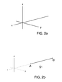
- This surface is obtained by applying the procedure set out below. First of all the three space axes X, Y and Z are determined (
Fig. 2a ). - Then a first segment S1 is drawn along axis X, which determines ends A and B (
Fig. 2b ). - Then a second segment S2 is drawn, with a length h other than zero, originating in the medium point M of the first segment S1 and parallel to axis Z that ends in point C (
Fig. 2c ). - Then, a first arch A1 is defined that passes through points A, C and B, defined beforehand, corresponding with the ends of segment S1 and one of the ends of segment S2 (
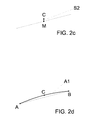
Fig. 2d ). - Then two circumferences are drawn with radius r1 centred in said points A and B. Said circumferences are parallel to plane YZ (
Fig. 2e ). - Next a circumference is drawn parallel to the previous ones with radius r2 and centred in point C, which is the end of segment S2 (
Fig. 2f ). - Afterwards a vector (vector MC) is defined starting in the point M of the first segment S1 and ending in point C, which as stated above, is the end of the second segment S2. A third segment S3 is drawn originating in point A of the first segment S1, in plane XZ, with length r1 in the direction of vector MC, with an end point of said segment being defined, point D (
Fig. 2g ). - Subsequently a fourth segment S4 is drawn originating in point B of the first segment S1, orientated in plane XZ, with length r1 in the direction of vector MC, with an end point of said fourth segment being defined, point E (
Fig. 2h ). - Then a fifth segment S5 is drawn originating in point C, which is the end of segment S2, in plane XZ, with length r2 in the direction of vector MC, with an end point of said fifth segment S5 being defined, point F (
Fig. 2i ). - Afterwards a second arch A2 is defined that passes through the above-mentioned points D, F and E (
Fig. 2j ). - Then a surface U1 is defined made up of all the circumferences parallel to plane YZ, centred in the first arch A1 and with one point of the perimeter thereof located in the second arch A2 (
Fig. 2k ). - Finally the first arch A1 is projected in the direction of axis Y on surface U1 producing two projections p1 and p2 which, when joined together, form piezoelectric ceramics radiating surface U2 (
Fig. 2I ), which can be cut as required (Fig. 2m ). - One of the embodiments of said piezoelectric ceramics in
Figure 2m , is like the one shown inFigures 3a, 3b and 3c , which are a plane, side and front view of that shown in saidFigure 2m . - According to requirements, radius r1 can be different from r2 or radii r1 and r2 can be identical.
- The said system, in
Figure 1 , comprises acontrol unit 5 that manages the emission time and the amplitude of the signal supplied to the amplifier. Also, this unit will set up other operating parameters, such as the emission mode, which can be continuous or pulsed, the working cycle, the number of impulses, etc. -
Signal generator 4 supplies the power amplifier 3 with an essential emission frequency, which is adjustable and coincides with the transducer resonance frequency. This generator can, possibly, work with harmonics in the essential frequency, in order to vary the transducer emission wavelength, and this way, reduce the size of the focus area. - The electrical impedance adaptation network 2 adapts the signal that leaves the amplifier 3 so that transducer 1 receives it correctly.
- In one embodiment it can be foreseen that the system detects whether the acoustic energy is deposited in the transducer focus. To this end, a
detection transducer 6 is added to the above-mentioned system, focused in the focus area of power transducer 1, to know whether cavitations occur in the focus point; asignal amplifier 8 is also added, if the received signal is weak; and asignal treatment block 9, which would be connected to controlunit 5, which analyses the signal to detect the cavitations; and an electricalimpedance adaptation network 7 which adapts the signal that leavestransducer 6 so that it is received correctly byamplifier 8. -
Figure 4 shows transducer 1 with itscasing 11, anelectrical lead 16 and anadaptation layer 15, which is explained in further detail inFigure 5 . -
Figure 5 is the section along the line V-V inFigure 4 , which illustratescasing 11, lead 16, anabsorbent material 12, apiezoelectric ceramics 14 sandwiched by a firstmetallic electrode 13 and a secondmetallic electrode 17 andadaptation layer 15. - This way, lead 16 with two connectors is attached to electrical impedances adaptation network 2.
-
Casing 11 surrounds and protects the various elements making up transducer 1. -
Absorbent material 12 absorbs the vibrations ofpiezoelectric ceramics 14 inside transducer 1. - First
metallic electrode 13 covers the whole top surface of the piezoelectric ceramics, to which one of the connectors oflead 16 is connected, and the secondmetallic electrode 17 covers the whole bottom surface ofpiezoelectric ceramics 14, to which the other connector ofelectric lead 16 is connected. -
Piezoelectric ceramics 14 produces the ultrasound vibration when it is excited to a certain frequency by the twometallic electrodes adaptation layer 15 which adapts the acoustic impedances of transducer 1 and of the medium (the part of the human body) that is going to be the exposed to the acoustic field. -
Figure 6 is a side tomography of the ultrasound action under the skin where aprefocus area 20,post focus area 21 and anarea 22 can be seen, the latter being where the acoustic pressure is greater and therefore where the temperature is also higher. -
Figure 7 is a plane tomography of the ultrasound action under the skin, after creating a transparent effect onpiezoelectric ceramics 21 to make it easier to see the tomography. - This invention describes a new procedure for the manufacturing of a piezoelectric ceramics radiating surface. The examples mentioned herein do not limit the invention, and therefore it can have different applications and/or adaptations, all within the scope of the following claims.
Claims (2)
- Procedure for the manufacturing of a piezoelectric ceramics radiating surface, of the type that is used in a powerful ultrasound transducer, said transducer being next to an electrical impedance adaptation network, a power amplifier, a signal generator, a control unit, said transducer also comprising an external casing, said piezoelectric ceramics between some electrodes, an absorbent material between the casing and piezoelectric ceramics and an adaptation layer, characterized in that piezoelectric ceramics radiating surface U2 is defined as part of a surface U1 that contains an arch A2 and is limited by two projections p1 and p2, without necessarily containing them and which are obtained by applying the following procedure:- the three space axes X, Y and Z are determined- a first segment S1 is drawn along axis X of ends A and B,- a second segment S2 is drawn, with a length h other than zero, originating in the medium point M of the first segment S1 and parallel to axis Z that ends in point C,- a first arch A1 is defined that passes through points A, C and B,- two circumferences are drawn with radius r1 centred in points A and B and in planes parallel to plane YZ,- a circumference is drawn parallel to the previous ones with radius r2, centred in C,- a vector is defined that starts at point M and ends at point C,- a third segment S3 is drawn originating in point A, in plane XZ, with length r1 in the direction of vector MC, with an end point of said segment being defined, point D,- a fourth segment S4 is drawn originating in point B, in plane XZ, with length r1 in the direction of vector MC, with an end point of said segment being defined, point E,- a fifth segment S5 is drawn originating in point C, in plane XZ, with length r2 in the direction of vector MC, with an end point of said segment being defined, point F,- a second arch A2 is defined that passes through points D, F and E,- a surface U1 is defined made up of all the circumferences parallel to plane YZ centred in the first arch A1 and with one point of the perimeter thereof located in second arch A2, and- first arch A1 is projected in the direction of axis Y on surface U1 producing two projections p1 and p2.
- Procedure according to claim 1 characterized in that radius r1 is different to radius r2.
Applications Claiming Priority (1)
| Application Number | Priority Date | Filing Date | Title |
|---|---|---|---|
| ES200801025A ES2358248B1 (en) | 2008-04-02 | 2008-04-02 | PROCEDURE FOR THE MANUFACTURE OF A RADIANT SURFACE OF A PIEZOELECTRIC CERAMIC. |
Publications (2)
| Publication Number | Publication Date |
|---|---|
| EP2106862A1 true EP2106862A1 (en) | 2009-10-07 |
| EP2106862B1 EP2106862B1 (en) | 2015-12-02 |
Family
ID=40833611
Family Applications (1)
| Application Number | Title | Priority Date | Filing Date |
|---|---|---|---|
| EP08160842.4A Not-in-force EP2106862B1 (en) | 2008-04-02 | 2008-07-21 | Procedure for the manufacturing of a piezoelectric ceramics radiating surface |
Country Status (2)
| Country | Link |
|---|---|
| EP (1) | EP2106862B1 (en) |
| ES (1) | ES2358248B1 (en) |
Cited By (1)
| Publication number | Priority date | Publication date | Assignee | Title |
|---|---|---|---|---|
| WO2012156838A1 (en) * | 2011-05-18 | 2012-11-22 | Koninklijke Philips Electronics N.V. | Spherical ultrasonic hifu transducer with offset cavitation sense element locations |
Citations (5)
| Publication number | Priority date | Publication date | Assignee | Title |
|---|---|---|---|---|
| EP1345657A1 (en) * | 2000-12-27 | 2003-09-24 | Insightec-Image Guided Treatment Ltd. | Ultrasound assisted lipolysis |
| US6656136B1 (en) * | 1999-10-25 | 2003-12-02 | Therus Corporation | Use of focused ultrasound for vascular sealing |
| WO2006021651A1 (en) * | 2004-07-23 | 2006-03-02 | Inserm | Ultrasound treating device and method |
| EP1774989A2 (en) * | 2005-10-13 | 2007-04-18 | UST Inc. | Treatment of cancer with high intensity focused ultrasound and chemotherapy |
| US20080027328A1 (en) * | 1997-12-29 | 2008-01-31 | Julia Therapeutics, Llc | Multi-focal treatment of skin with acoustic energy |
-
2008
- 2008-04-02 ES ES200801025A patent/ES2358248B1/en not_active Expired - Fee Related
- 2008-07-21 EP EP08160842.4A patent/EP2106862B1/en not_active Not-in-force
Patent Citations (5)
| Publication number | Priority date | Publication date | Assignee | Title |
|---|---|---|---|---|
| US20080027328A1 (en) * | 1997-12-29 | 2008-01-31 | Julia Therapeutics, Llc | Multi-focal treatment of skin with acoustic energy |
| US6656136B1 (en) * | 1999-10-25 | 2003-12-02 | Therus Corporation | Use of focused ultrasound for vascular sealing |
| EP1345657A1 (en) * | 2000-12-27 | 2003-09-24 | Insightec-Image Guided Treatment Ltd. | Ultrasound assisted lipolysis |
| WO2006021651A1 (en) * | 2004-07-23 | 2006-03-02 | Inserm | Ultrasound treating device and method |
| EP1774989A2 (en) * | 2005-10-13 | 2007-04-18 | UST Inc. | Treatment of cancer with high intensity focused ultrasound and chemotherapy |
Cited By (1)
| Publication number | Priority date | Publication date | Assignee | Title |
|---|---|---|---|---|
| WO2012156838A1 (en) * | 2011-05-18 | 2012-11-22 | Koninklijke Philips Electronics N.V. | Spherical ultrasonic hifu transducer with offset cavitation sense element locations |
Also Published As
| Publication number | Publication date |
|---|---|
| ES2358248B1 (en) | 2012-03-01 |
| ES2358248A1 (en) | 2011-05-09 |
| EP2106862B1 (en) | 2015-12-02 |
Similar Documents
| Publication | Publication Date | Title |
|---|---|---|
| US8858471B2 (en) | Methods and systems for ultrasound treatment | |
| US8298162B2 (en) | Skin and adipose tissue treatment by nonfocalized opposing side shock waves | |
| US8133191B2 (en) | Method and apparatus for treatment of adipose tissue | |
| US8162858B2 (en) | Ultrasonic medical treatment device with variable focal zone | |
| US20180099163A1 (en) | Apparatus and method for damaging or destroying adipocytes | |
| WO2016204957A1 (en) | Apparatus and method for damaging or destroying adipocytes | |
| US20040215110A1 (en) | Method and device for adipose tissue treatment | |
| US11413477B2 (en) | Transfection and drug delivery | |
| EP2106862B1 (en) | Procedure for the manufacturing of a piezoelectric ceramics radiating surface | |
| CN203874298U (en) | Multi-frequency ultrasonic tumor treatment head | |
| US20210236861A1 (en) | Portable ultrasonic stimulator | |
| Rybyanets et al. | New combinational method for noninvasive treatments of superficial tissues for body aesthetics applications | |
| KR20130121258A (en) | High intensity focused ultrasound generating device and method for the deduction of fat tissue | |
| CN107921280A (en) | For producing the medical treatment device of ultrasonic wave and electrical stimulation signal | |
| KR20200105104A (en) | Beauty equipment | |
| KR20200077863A (en) | Mobile ultrasonic stimulation apparatus | |
| EP2762195B1 (en) | Pressure-assisted irreversible electroporation | |
| KR20230134034A (en) | Portable HIFU Skin Treatment Device Using Curved Planar Oscillator | |
| US20220347495A1 (en) | Pain relief apparatus induced spiral vortex based on ultrasound and vacuum pulse | |
| Shvetsova et al. | Combinational Radiofrequency Electromagnetic and Ultrasonic Methods for Medical Applications | |
| TWI651109B (en) | Therapeutic ultrasonic device and the use thereof | |
| KR20040069377A (en) | A thermo-hydraulic shock wave generator | |
| Kojima et al. | Basic Study of Ultrasound Hyperthermia Using Acrylic Guide | |
| KR101356431B1 (en) | High intensity focused ultrasound generating device for deduction of fat tissue | |
| CN116511014A (en) | Single/double-frequency array transducer for multiple regulation and control of sound field and focal domain volume |
Legal Events
| Date | Code | Title | Description |
|---|---|---|---|
| PUAI | Public reference made under article 153(3) epc to a published international application that has entered the european phase |
Free format text: ORIGINAL CODE: 0009012 |
|
| AK | Designated contracting states |
Kind code of ref document: A1 Designated state(s): AT BE BG CH CY CZ DE DK EE ES FI FR GB GR HR HU IE IS IT LI LT LU LV MC MT NL NO PL PT RO SE SI SK TR |
|
| AX | Request for extension of the european patent |
Extension state: AL BA MK RS |
|
| 17P | Request for examination filed |
Effective date: 20100329 |
|
| 17Q | First examination report despatched |
Effective date: 20100429 |
|
| AKX | Designation fees paid |
Designated state(s): AT BE BG CH CY CZ DE DK EE ES FI FR GB GR HR HU IE IS IT LI LT LU LV MC MT NL NO PL PT RO SE SI SK TR |
|
| GRAP | Despatch of communication of intention to grant a patent |
Free format text: ORIGINAL CODE: EPIDOSNIGR1 |
|
| INTG | Intention to grant announced |
Effective date: 20150410 |
|
| RIN1 | Information on inventor provided before grant (corrected) |
Inventor name: SANCHEZ SORIANO, MANUEL Inventor name: COUSSIOS, CONSTANTIN CASSIOS Inventor name: AMAT GENIS, ALBERTO Inventor name: BRUGUERA GUDAYOL, EDUARD Inventor name: KYRIAKOU, ZOE Inventor name: VADILLO PASTOR, JUAN RAMON Inventor name: CORRAL BAQUES, MARC IGNASI |
|
| GRAS | Grant fee paid |
Free format text: ORIGINAL CODE: EPIDOSNIGR3 |
|
| RAP1 | Party data changed (applicant data changed or rights of an application transferred) |
Owner name: INDIBA, S.A. |
|
| GRAA | (expected) grant |
Free format text: ORIGINAL CODE: 0009210 |
|
| AK | Designated contracting states |
Kind code of ref document: B1 Designated state(s): AT BE BG CH CY CZ DE DK EE ES FI FR GB GR HR HU IE IS IT LI LT LU LV MC MT NL NO PL PT RO SE SI SK TR |
|
| REG | Reference to a national code |
Ref country code: GB Ref legal event code: FG4D |
|
| REG | Reference to a national code |
Ref country code: AT Ref legal event code: REF Ref document number: 763389 Country of ref document: AT Kind code of ref document: T Effective date: 20151215 Ref country code: CH Ref legal event code: EP |
|
| REG | Reference to a national code |
Ref country code: IE Ref legal event code: FG4D |
|
| REG | Reference to a national code |
Ref country code: DE Ref legal event code: R096 Ref document number: 602008041365 Country of ref document: DE |
|
| REG | Reference to a national code |
Ref country code: NL Ref legal event code: MP Effective date: 20160302 |
|
| REG | Reference to a national code |
Ref country code: LT Ref legal event code: MG4D |
|
| REG | Reference to a national code |
Ref country code: AT Ref legal event code: MK05 Ref document number: 763389 Country of ref document: AT Kind code of ref document: T Effective date: 20151202 |
|
| PG25 | Lapsed in a contracting state [announced via postgrant information from national office to epo] |
Ref country code: NO Free format text: LAPSE BECAUSE OF FAILURE TO SUBMIT A TRANSLATION OF THE DESCRIPTION OR TO PAY THE FEE WITHIN THE PRESCRIBED TIME-LIMIT Effective date: 20160302 Ref country code: ES Free format text: LAPSE BECAUSE OF FAILURE TO SUBMIT A TRANSLATION OF THE DESCRIPTION OR TO PAY THE FEE WITHIN THE PRESCRIBED TIME-LIMIT Effective date: 20151202 Ref country code: HR Free format text: LAPSE BECAUSE OF FAILURE TO SUBMIT A TRANSLATION OF THE DESCRIPTION OR TO PAY THE FEE WITHIN THE PRESCRIBED TIME-LIMIT Effective date: 20151202 Ref country code: LT Free format text: LAPSE BECAUSE OF FAILURE TO SUBMIT A TRANSLATION OF THE DESCRIPTION OR TO PAY THE FEE WITHIN THE PRESCRIBED TIME-LIMIT Effective date: 20151202 |
|
| PG25 | Lapsed in a contracting state [announced via postgrant information from national office to epo] |
Ref country code: NL Free format text: LAPSE BECAUSE OF FAILURE TO SUBMIT A TRANSLATION OF THE DESCRIPTION OR TO PAY THE FEE WITHIN THE PRESCRIBED TIME-LIMIT Effective date: 20151202 Ref country code: GR Free format text: LAPSE BECAUSE OF FAILURE TO SUBMIT A TRANSLATION OF THE DESCRIPTION OR TO PAY THE FEE WITHIN THE PRESCRIBED TIME-LIMIT Effective date: 20160303 Ref country code: AT Free format text: LAPSE BECAUSE OF FAILURE TO SUBMIT A TRANSLATION OF THE DESCRIPTION OR TO PAY THE FEE WITHIN THE PRESCRIBED TIME-LIMIT Effective date: 20151202 Ref country code: PL Free format text: LAPSE BECAUSE OF FAILURE TO SUBMIT A TRANSLATION OF THE DESCRIPTION OR TO PAY THE FEE WITHIN THE PRESCRIBED TIME-LIMIT Effective date: 20151202 Ref country code: SE Free format text: LAPSE BECAUSE OF FAILURE TO SUBMIT A TRANSLATION OF THE DESCRIPTION OR TO PAY THE FEE WITHIN THE PRESCRIBED TIME-LIMIT Effective date: 20151202 Ref country code: FI Free format text: LAPSE BECAUSE OF FAILURE TO SUBMIT A TRANSLATION OF THE DESCRIPTION OR TO PAY THE FEE WITHIN THE PRESCRIBED TIME-LIMIT Effective date: 20151202 Ref country code: LV Free format text: LAPSE BECAUSE OF FAILURE TO SUBMIT A TRANSLATION OF THE DESCRIPTION OR TO PAY THE FEE WITHIN THE PRESCRIBED TIME-LIMIT Effective date: 20151202 |
|
| PG25 | Lapsed in a contracting state [announced via postgrant information from national office to epo] |
Ref country code: IS Free format text: LAPSE BECAUSE OF FAILURE TO SUBMIT A TRANSLATION OF THE DESCRIPTION OR TO PAY THE FEE WITHIN THE PRESCRIBED TIME-LIMIT Effective date: 20151202 |
|
| PG25 | Lapsed in a contracting state [announced via postgrant information from national office to epo] |
Ref country code: IT Free format text: LAPSE BECAUSE OF FAILURE TO SUBMIT A TRANSLATION OF THE DESCRIPTION OR TO PAY THE FEE WITHIN THE PRESCRIBED TIME-LIMIT Effective date: 20151202 Ref country code: CZ Free format text: LAPSE BECAUSE OF FAILURE TO SUBMIT A TRANSLATION OF THE DESCRIPTION OR TO PAY THE FEE WITHIN THE PRESCRIBED TIME-LIMIT Effective date: 20151202 |
|
| PG25 | Lapsed in a contracting state [announced via postgrant information from national office to epo] |
Ref country code: PT Free format text: LAPSE BECAUSE OF FAILURE TO SUBMIT A TRANSLATION OF THE DESCRIPTION OR TO PAY THE FEE WITHIN THE PRESCRIBED TIME-LIMIT Effective date: 20160404 Ref country code: SK Free format text: LAPSE BECAUSE OF FAILURE TO SUBMIT A TRANSLATION OF THE DESCRIPTION OR TO PAY THE FEE WITHIN THE PRESCRIBED TIME-LIMIT Effective date: 20151202 Ref country code: EE Free format text: LAPSE BECAUSE OF FAILURE TO SUBMIT A TRANSLATION OF THE DESCRIPTION OR TO PAY THE FEE WITHIN THE PRESCRIBED TIME-LIMIT Effective date: 20151202 Ref country code: IS Free format text: LAPSE BECAUSE OF FAILURE TO SUBMIT A TRANSLATION OF THE DESCRIPTION OR TO PAY THE FEE WITHIN THE PRESCRIBED TIME-LIMIT Effective date: 20160402 Ref country code: RO Free format text: LAPSE BECAUSE OF FAILURE TO SUBMIT A TRANSLATION OF THE DESCRIPTION OR TO PAY THE FEE WITHIN THE PRESCRIBED TIME-LIMIT Effective date: 20151202 |
|
| REG | Reference to a national code |
Ref country code: DE Ref legal event code: R097 Ref document number: 602008041365 Country of ref document: DE |
|
| PLBE | No opposition filed within time limit |
Free format text: ORIGINAL CODE: 0009261 |
|
| STAA | Information on the status of an ep patent application or granted ep patent |
Free format text: STATUS: NO OPPOSITION FILED WITHIN TIME LIMIT |
|
| PG25 | Lapsed in a contracting state [announced via postgrant information from national office to epo] |
Ref country code: DK Free format text: LAPSE BECAUSE OF FAILURE TO SUBMIT A TRANSLATION OF THE DESCRIPTION OR TO PAY THE FEE WITHIN THE PRESCRIBED TIME-LIMIT Effective date: 20151202 |
|
| 26N | No opposition filed |
Effective date: 20160905 |
|
| PG25 | Lapsed in a contracting state [announced via postgrant information from national office to epo] |
Ref country code: SI Free format text: LAPSE BECAUSE OF FAILURE TO SUBMIT A TRANSLATION OF THE DESCRIPTION OR TO PAY THE FEE WITHIN THE PRESCRIBED TIME-LIMIT Effective date: 20151202 |
|
| PG25 | Lapsed in a contracting state [announced via postgrant information from national office to epo] |
Ref country code: BE Free format text: LAPSE BECAUSE OF FAILURE TO SUBMIT A TRANSLATION OF THE DESCRIPTION OR TO PAY THE FEE WITHIN THE PRESCRIBED TIME-LIMIT Effective date: 20151202 |
|
| REG | Reference to a national code |
Ref country code: DE Ref legal event code: R119 Ref document number: 602008041365 Country of ref document: DE |
|
| REG | Reference to a national code |
Ref country code: CH Ref legal event code: PL |
|
| GBPC | Gb: european patent ceased through non-payment of renewal fee |
Effective date: 20160721 |
|
| PG25 | Lapsed in a contracting state [announced via postgrant information from national office to epo] |
Ref country code: MC Free format text: LAPSE BECAUSE OF FAILURE TO SUBMIT A TRANSLATION OF THE DESCRIPTION OR TO PAY THE FEE WITHIN THE PRESCRIBED TIME-LIMIT Effective date: 20151202 |
|
| PG25 | Lapsed in a contracting state [announced via postgrant information from national office to epo] |
Ref country code: LI Free format text: LAPSE BECAUSE OF NON-PAYMENT OF DUE FEES Effective date: 20160731 Ref country code: DE Free format text: LAPSE BECAUSE OF NON-PAYMENT OF DUE FEES Effective date: 20170201 Ref country code: FR Free format text: LAPSE BECAUSE OF NON-PAYMENT OF DUE FEES Effective date: 20160801 Ref country code: CH Free format text: LAPSE BECAUSE OF NON-PAYMENT OF DUE FEES Effective date: 20160731 |
|
| REG | Reference to a national code |
Ref country code: FR Ref legal event code: ST Effective date: 20170331 |
|
| REG | Reference to a national code |
Ref country code: IE Ref legal event code: MM4A |
|
| PG25 | Lapsed in a contracting state [announced via postgrant information from national office to epo] |
Ref country code: GB Free format text: LAPSE BECAUSE OF NON-PAYMENT OF DUE FEES Effective date: 20160721 |
|
| PG25 | Lapsed in a contracting state [announced via postgrant information from national office to epo] |
Ref country code: IE Free format text: LAPSE BECAUSE OF NON-PAYMENT OF DUE FEES Effective date: 20160721 |
|
| PG25 | Lapsed in a contracting state [announced via postgrant information from national office to epo] |
Ref country code: LU Free format text: LAPSE BECAUSE OF NON-PAYMENT OF DUE FEES Effective date: 20160721 |
|
| PG25 | Lapsed in a contracting state [announced via postgrant information from national office to epo] |
Ref country code: HU Free format text: LAPSE BECAUSE OF FAILURE TO SUBMIT A TRANSLATION OF THE DESCRIPTION OR TO PAY THE FEE WITHIN THE PRESCRIBED TIME-LIMIT; INVALID AB INITIO Effective date: 20080721 Ref country code: CY Free format text: LAPSE BECAUSE OF FAILURE TO SUBMIT A TRANSLATION OF THE DESCRIPTION OR TO PAY THE FEE WITHIN THE PRESCRIBED TIME-LIMIT Effective date: 20151202 |
|
| PG25 | Lapsed in a contracting state [announced via postgrant information from national office to epo] |
Ref country code: MT Free format text: LAPSE BECAUSE OF NON-PAYMENT OF DUE FEES Effective date: 20160731 Ref country code: TR Free format text: LAPSE BECAUSE OF FAILURE TO SUBMIT A TRANSLATION OF THE DESCRIPTION OR TO PAY THE FEE WITHIN THE PRESCRIBED TIME-LIMIT Effective date: 20151202 |
|
| PG25 | Lapsed in a contracting state [announced via postgrant information from national office to epo] |
Ref country code: BG Free format text: LAPSE BECAUSE OF FAILURE TO SUBMIT A TRANSLATION OF THE DESCRIPTION OR TO PAY THE FEE WITHIN THE PRESCRIBED TIME-LIMIT Effective date: 20151202 |