EP2106841A1 - Apparatus for purifying exhaust gas - Google Patents
Apparatus for purifying exhaust gas Download PDFInfo
- Publication number
- EP2106841A1 EP2106841A1 EP08168838A EP08168838A EP2106841A1 EP 2106841 A1 EP2106841 A1 EP 2106841A1 EP 08168838 A EP08168838 A EP 08168838A EP 08168838 A EP08168838 A EP 08168838A EP 2106841 A1 EP2106841 A1 EP 2106841A1
- Authority
- EP
- European Patent Office
- Prior art keywords
- doc
- exhaust gas
- approximately
- cpf
- noble metal
- Prior art date
- Legal status (The legal status is an assumption and is not a legal conclusion. Google has not performed a legal analysis and makes no representation as to the accuracy of the status listed.)
- Granted
Links
Images



Classifications
-
- F—MECHANICAL ENGINEERING; LIGHTING; HEATING; WEAPONS; BLASTING
- F01—MACHINES OR ENGINES IN GENERAL; ENGINE PLANTS IN GENERAL; STEAM ENGINES
- F01N—GAS-FLOW SILENCERS OR EXHAUST APPARATUS FOR MACHINES OR ENGINES IN GENERAL; GAS-FLOW SILENCERS OR EXHAUST APPARATUS FOR INTERNAL-COMBUSTION ENGINES
- F01N3/00—Exhaust or silencing apparatus having means for purifying, rendering innocuous, or otherwise treating exhaust
- F01N3/08—Exhaust or silencing apparatus having means for purifying, rendering innocuous, or otherwise treating exhaust for rendering innocuous
- F01N3/10—Exhaust or silencing apparatus having means for purifying, rendering innocuous, or otherwise treating exhaust for rendering innocuous by thermal or catalytic conversion of noxious components of exhaust
- F01N3/18—Exhaust or silencing apparatus having means for purifying, rendering innocuous, or otherwise treating exhaust for rendering innocuous by thermal or catalytic conversion of noxious components of exhaust characterised by methods of operation; Control
- F01N3/20—Exhaust or silencing apparatus having means for purifying, rendering innocuous, or otherwise treating exhaust for rendering innocuous by thermal or catalytic conversion of noxious components of exhaust characterised by methods of operation; Control specially adapted for catalytic conversion
- F01N3/206—Adding periodically or continuously substances to exhaust gases for promoting purification, e.g. catalytic material in liquid form, NOx reducing agents
- F01N3/2066—Selective catalytic reduction [SCR]
-
- F—MECHANICAL ENGINEERING; LIGHTING; HEATING; WEAPONS; BLASTING
- F01—MACHINES OR ENGINES IN GENERAL; ENGINE PLANTS IN GENERAL; STEAM ENGINES
- F01N—GAS-FLOW SILENCERS OR EXHAUST APPARATUS FOR MACHINES OR ENGINES IN GENERAL; GAS-FLOW SILENCERS OR EXHAUST APPARATUS FOR INTERNAL-COMBUSTION ENGINES
- F01N3/00—Exhaust or silencing apparatus having means for purifying, rendering innocuous, or otherwise treating exhaust
- F01N3/08—Exhaust or silencing apparatus having means for purifying, rendering innocuous, or otherwise treating exhaust for rendering innocuous
- F01N3/10—Exhaust or silencing apparatus having means for purifying, rendering innocuous, or otherwise treating exhaust for rendering innocuous by thermal or catalytic conversion of noxious components of exhaust
- F01N3/24—Exhaust or silencing apparatus having means for purifying, rendering innocuous, or otherwise treating exhaust for rendering innocuous by thermal or catalytic conversion of noxious components of exhaust characterised by constructional aspects of converting apparatus
- F01N3/28—Construction of catalytic reactors
-
- B—PERFORMING OPERATIONS; TRANSPORTING
- B01—PHYSICAL OR CHEMICAL PROCESSES OR APPARATUS IN GENERAL
- B01D—SEPARATION
- B01D53/00—Separation of gases or vapours; Recovering vapours of volatile solvents from gases; Chemical or biological purification of waste gases, e.g. engine exhaust gases, smoke, fumes, flue gases, aerosols
- B01D53/34—Chemical or biological purification of waste gases
- B01D53/92—Chemical or biological purification of waste gases of engine exhaust gases
- B01D53/94—Chemical or biological purification of waste gases of engine exhaust gases by catalytic processes
- B01D53/9404—Removing only nitrogen compounds
- B01D53/9409—Nitrogen oxides
- B01D53/9413—Processes characterised by a specific catalyst
- B01D53/9418—Processes characterised by a specific catalyst for removing nitrogen oxides by selective catalytic reduction [SCR] using a reducing agent in a lean exhaust gas
-
- B—PERFORMING OPERATIONS; TRANSPORTING
- B01—PHYSICAL OR CHEMICAL PROCESSES OR APPARATUS IN GENERAL
- B01D—SEPARATION
- B01D53/00—Separation of gases or vapours; Recovering vapours of volatile solvents from gases; Chemical or biological purification of waste gases, e.g. engine exhaust gases, smoke, fumes, flue gases, aerosols
- B01D53/34—Chemical or biological purification of waste gases
- B01D53/92—Chemical or biological purification of waste gases of engine exhaust gases
- B01D53/94—Chemical or biological purification of waste gases of engine exhaust gases by catalytic processes
- B01D53/944—Simultaneously removing carbon monoxide, hydrocarbons or carbon making use of oxidation catalysts
-
- B—PERFORMING OPERATIONS; TRANSPORTING
- B01—PHYSICAL OR CHEMICAL PROCESSES OR APPARATUS IN GENERAL
- B01J—CHEMICAL OR PHYSICAL PROCESSES, e.g. CATALYSIS OR COLLOID CHEMISTRY; THEIR RELEVANT APPARATUS
- B01J23/00—Catalysts comprising metals or metal oxides or hydroxides, not provided for in group B01J21/00
- B01J23/38—Catalysts comprising metals or metal oxides or hydroxides, not provided for in group B01J21/00 of noble metals
- B01J23/40—Catalysts comprising metals or metal oxides or hydroxides, not provided for in group B01J21/00 of noble metals of the platinum group metals
- B01J23/42—Platinum
-
- B—PERFORMING OPERATIONS; TRANSPORTING
- B01—PHYSICAL OR CHEMICAL PROCESSES OR APPARATUS IN GENERAL
- B01J—CHEMICAL OR PHYSICAL PROCESSES, e.g. CATALYSIS OR COLLOID CHEMISTRY; THEIR RELEVANT APPARATUS
- B01J23/00—Catalysts comprising metals or metal oxides or hydroxides, not provided for in group B01J21/00
- B01J23/38—Catalysts comprising metals or metal oxides or hydroxides, not provided for in group B01J21/00 of noble metals
- B01J23/40—Catalysts comprising metals or metal oxides or hydroxides, not provided for in group B01J21/00 of noble metals of the platinum group metals
- B01J23/44—Palladium
-
- B—PERFORMING OPERATIONS; TRANSPORTING
- B01—PHYSICAL OR CHEMICAL PROCESSES OR APPARATUS IN GENERAL
- B01J—CHEMICAL OR PHYSICAL PROCESSES, e.g. CATALYSIS OR COLLOID CHEMISTRY; THEIR RELEVANT APPARATUS
- B01J29/00—Catalysts comprising molecular sieves
- B01J29/04—Catalysts comprising molecular sieves having base-exchange properties, e.g. crystalline zeolites
- B01J29/06—Crystalline aluminosilicate zeolites; Isomorphous compounds thereof
- B01J29/064—Crystalline aluminosilicate zeolites; Isomorphous compounds thereof containing iron group metals, noble metals or copper
- B01J29/072—Iron group metals or copper
-
- B—PERFORMING OPERATIONS; TRANSPORTING
- B01—PHYSICAL OR CHEMICAL PROCESSES OR APPARATUS IN GENERAL
- B01J—CHEMICAL OR PHYSICAL PROCESSES, e.g. CATALYSIS OR COLLOID CHEMISTRY; THEIR RELEVANT APPARATUS
- B01J35/00—Catalysts, in general, characterised by their form or physical properties
- B01J35/19—Catalysts containing parts with different compositions
-
- F—MECHANICAL ENGINEERING; LIGHTING; HEATING; WEAPONS; BLASTING
- F01—MACHINES OR ENGINES IN GENERAL; ENGINE PLANTS IN GENERAL; STEAM ENGINES
- F01N—GAS-FLOW SILENCERS OR EXHAUST APPARATUS FOR MACHINES OR ENGINES IN GENERAL; GAS-FLOW SILENCERS OR EXHAUST APPARATUS FOR INTERNAL-COMBUSTION ENGINES
- F01N13/00—Exhaust or silencing apparatus characterised by constructional features
- F01N13/009—Exhaust or silencing apparatus characterised by constructional features having two or more separate purifying devices arranged in series
-
- F—MECHANICAL ENGINEERING; LIGHTING; HEATING; WEAPONS; BLASTING
- F01—MACHINES OR ENGINES IN GENERAL; ENGINE PLANTS IN GENERAL; STEAM ENGINES
- F01N—GAS-FLOW SILENCERS OR EXHAUST APPARATUS FOR MACHINES OR ENGINES IN GENERAL; GAS-FLOW SILENCERS OR EXHAUST APPARATUS FOR INTERNAL-COMBUSTION ENGINES
- F01N3/00—Exhaust or silencing apparatus having means for purifying, rendering innocuous, or otherwise treating exhaust
- F01N3/02—Exhaust or silencing apparatus having means for purifying, rendering innocuous, or otherwise treating exhaust for cooling, or for removing solid constituents of, exhaust
- F01N3/021—Exhaust or silencing apparatus having means for purifying, rendering innocuous, or otherwise treating exhaust for cooling, or for removing solid constituents of, exhaust by means of filters
- F01N3/033—Exhaust or silencing apparatus having means for purifying, rendering innocuous, or otherwise treating exhaust for cooling, or for removing solid constituents of, exhaust by means of filters in combination with other devices
- F01N3/035—Exhaust or silencing apparatus having means for purifying, rendering innocuous, or otherwise treating exhaust for cooling, or for removing solid constituents of, exhaust by means of filters in combination with other devices with catalytic reactors
-
- F—MECHANICAL ENGINEERING; LIGHTING; HEATING; WEAPONS; BLASTING
- F01—MACHINES OR ENGINES IN GENERAL; ENGINE PLANTS IN GENERAL; STEAM ENGINES
- F01N—GAS-FLOW SILENCERS OR EXHAUST APPARATUS FOR MACHINES OR ENGINES IN GENERAL; GAS-FLOW SILENCERS OR EXHAUST APPARATUS FOR INTERNAL-COMBUSTION ENGINES
- F01N3/00—Exhaust or silencing apparatus having means for purifying, rendering innocuous, or otherwise treating exhaust
- F01N3/08—Exhaust or silencing apparatus having means for purifying, rendering innocuous, or otherwise treating exhaust for rendering innocuous
- F01N3/10—Exhaust or silencing apparatus having means for purifying, rendering innocuous, or otherwise treating exhaust for rendering innocuous by thermal or catalytic conversion of noxious components of exhaust
- F01N3/24—Exhaust or silencing apparatus having means for purifying, rendering innocuous, or otherwise treating exhaust for rendering innocuous by thermal or catalytic conversion of noxious components of exhaust characterised by constructional aspects of converting apparatus
-
- B—PERFORMING OPERATIONS; TRANSPORTING
- B01—PHYSICAL OR CHEMICAL PROCESSES OR APPARATUS IN GENERAL
- B01D—SEPARATION
- B01D2255/00—Catalysts
- B01D2255/10—Noble metals or compounds thereof
- B01D2255/102—Platinum group metals
- B01D2255/1021—Platinum
-
- B—PERFORMING OPERATIONS; TRANSPORTING
- B01—PHYSICAL OR CHEMICAL PROCESSES OR APPARATUS IN GENERAL
- B01D—SEPARATION
- B01D2255/00—Catalysts
- B01D2255/10—Noble metals or compounds thereof
- B01D2255/102—Platinum group metals
- B01D2255/1023—Palladium
-
- B—PERFORMING OPERATIONS; TRANSPORTING
- B01—PHYSICAL OR CHEMICAL PROCESSES OR APPARATUS IN GENERAL
- B01D—SEPARATION
- B01D2255/00—Catalysts
- B01D2255/20—Metals or compounds thereof
- B01D2255/207—Transition metals
- B01D2255/20738—Iron
-
- B—PERFORMING OPERATIONS; TRANSPORTING
- B01—PHYSICAL OR CHEMICAL PROCESSES OR APPARATUS IN GENERAL
- B01D—SEPARATION
- B01D2255/00—Catalysts
- B01D2255/20—Metals or compounds thereof
- B01D2255/207—Transition metals
- B01D2255/20761—Copper
-
- B—PERFORMING OPERATIONS; TRANSPORTING
- B01—PHYSICAL OR CHEMICAL PROCESSES OR APPARATUS IN GENERAL
- B01D—SEPARATION
- B01D2255/00—Catalysts
- B01D2255/50—Zeolites
-
- B—PERFORMING OPERATIONS; TRANSPORTING
- B01—PHYSICAL OR CHEMICAL PROCESSES OR APPARATUS IN GENERAL
- B01D—SEPARATION
- B01D2258/00—Sources of waste gases
- B01D2258/01—Engine exhaust gases
- B01D2258/012—Diesel engines and lean burn gasoline engines
-
- B—PERFORMING OPERATIONS; TRANSPORTING
- B01—PHYSICAL OR CHEMICAL PROCESSES OR APPARATUS IN GENERAL
- B01D—SEPARATION
- B01D53/00—Separation of gases or vapours; Recovering vapours of volatile solvents from gases; Chemical or biological purification of waste gases, e.g. engine exhaust gases, smoke, fumes, flue gases, aerosols
- B01D53/34—Chemical or biological purification of waste gases
- B01D53/92—Chemical or biological purification of waste gases of engine exhaust gases
- B01D53/94—Chemical or biological purification of waste gases of engine exhaust gases by catalytic processes
- B01D53/9459—Removing one or more of nitrogen oxides, carbon monoxide, or hydrocarbons by multiple successive catalytic functions; systems with more than one different function, e.g. zone coated catalysts
- B01D53/9477—Removing one or more of nitrogen oxides, carbon monoxide, or hydrocarbons by multiple successive catalytic functions; systems with more than one different function, e.g. zone coated catalysts with catalysts positioned on separate bricks, e.g. exhaust systems
-
- F—MECHANICAL ENGINEERING; LIGHTING; HEATING; WEAPONS; BLASTING
- F01—MACHINES OR ENGINES IN GENERAL; ENGINE PLANTS IN GENERAL; STEAM ENGINES
- F01N—GAS-FLOW SILENCERS OR EXHAUST APPARATUS FOR MACHINES OR ENGINES IN GENERAL; GAS-FLOW SILENCERS OR EXHAUST APPARATUS FOR INTERNAL-COMBUSTION ENGINES
- F01N2250/00—Combinations of different methods of purification
- F01N2250/02—Combinations of different methods of purification filtering and catalytic conversion
-
- F—MECHANICAL ENGINEERING; LIGHTING; HEATING; WEAPONS; BLASTING
- F01—MACHINES OR ENGINES IN GENERAL; ENGINE PLANTS IN GENERAL; STEAM ENGINES
- F01N—GAS-FLOW SILENCERS OR EXHAUST APPARATUS FOR MACHINES OR ENGINES IN GENERAL; GAS-FLOW SILENCERS OR EXHAUST APPARATUS FOR INTERNAL-COMBUSTION ENGINES
- F01N2510/00—Surface coverings
- F01N2510/06—Surface coverings for exhaust purification, e.g. catalytic reaction
- F01N2510/068—Surface coverings for exhaust purification, e.g. catalytic reaction characterised by the distribution of the catalytic coatings
- F01N2510/0682—Surface coverings for exhaust purification, e.g. catalytic reaction characterised by the distribution of the catalytic coatings having a discontinuous, uneven or partially overlapping coating of catalytic material, e.g. higher amount of material upstream than downstream or vice versa
-
- Y—GENERAL TAGGING OF NEW TECHNOLOGICAL DEVELOPMENTS; GENERAL TAGGING OF CROSS-SECTIONAL TECHNOLOGIES SPANNING OVER SEVERAL SECTIONS OF THE IPC; TECHNICAL SUBJECTS COVERED BY FORMER USPC CROSS-REFERENCE ART COLLECTIONS [XRACs] AND DIGESTS
- Y02—TECHNOLOGIES OR APPLICATIONS FOR MITIGATION OR ADAPTATION AGAINST CLIMATE CHANGE
- Y02A—TECHNOLOGIES FOR ADAPTATION TO CLIMATE CHANGE
- Y02A50/00—TECHNOLOGIES FOR ADAPTATION TO CLIMATE CHANGE in human health protection, e.g. against extreme weather
- Y02A50/20—Air quality improvement or preservation, e.g. vehicle emission control or emission reduction by using catalytic converters
-
- Y—GENERAL TAGGING OF NEW TECHNOLOGICAL DEVELOPMENTS; GENERAL TAGGING OF CROSS-SECTIONAL TECHNOLOGIES SPANNING OVER SEVERAL SECTIONS OF THE IPC; TECHNICAL SUBJECTS COVERED BY FORMER USPC CROSS-REFERENCE ART COLLECTIONS [XRACs] AND DIGESTS
- Y02—TECHNOLOGIES OR APPLICATIONS FOR MITIGATION OR ADAPTATION AGAINST CLIMATE CHANGE
- Y02T—CLIMATE CHANGE MITIGATION TECHNOLOGIES RELATED TO TRANSPORTATION
- Y02T10/00—Road transport of goods or passengers
- Y02T10/10—Internal combustion engine [ICE] based vehicles
- Y02T10/12—Improving ICE efficiencies
Definitions
- the present invention relates to an apparatus for purifying exhaust gas of vehicles. More particularly, the present invention relates to an apparatus for purifying exhaust gas that reduces hydrocarbon (HC), carbon monoxide (CO), particulate material (PM), and nitrogen oxide (NO x ) contained in the exhaust gas.
- HC hydrocarbon
- CO carbon monoxide
- PM particulate material
- NO x nitrogen oxide
- exhaust gas flowing out through an exhaust manifold from an engine is driven into a catalytic converter mounted at an exhaust pipe and is purified therein. After that, the noise of the exhaust gas is decreased while passing through a muffler and then the exhaust gas is emitted into the air through a tail pipe.
- the catalytic converter is a type of diesel particulate filter (DPF) and purifies pollutants contained in the exhaust gas.
- a catalytic carrier for trapping particulate material (PM) contained in the exhaust gas is in the catalytic converter, and the exhaust gas flowing out from the engine is purified through a chemical reaction therein.
- One type of catalytic converter is a selective catalytic reduction (SCR) apparatus.
- SCR selective catalytic reduction
- reducing agents such as carbon monoxide and total hydrocarbon (THC) react better with nitrogen oxide than oxygen.
- THC total hydrocarbon
- a diesel oxidation catalyst (DOC) device oxidizes total hydrocarbon (THC) and carbon monoxide (CO), and oxidizes nitrogen monoxide (NO) into nitrogen dioxide (NO 2 ).
- an SCR device reduces nitrogen oxides (NO x ) into nitrogen gas (N 2 ) by using the NO 2 generated in the DOC device and a reducing agent.
- EGR exhaust gas regeneration
- the NO 2 generated by oxidizing NO is used in the DOC device when the THC and the CO are oxidized during cool starting. That is, the NO 2 is used when the THC and the CO are oxidized at a low temperature.
- Equation 1 represents a soot regeneration reaction performed in the CPF device.
- Various aspects of the present invention are directed to provide an apparatus for purifying exhaust gas having advantages of fully oxidizing HC and CO contained in the exhaust gas and sufficiently reducing NO x by causing NO 2 generated in the oxidation of the HC and the CO to be sufficiently supplied to an SCR device as a consequence of disposing a DOC device between a CPF device and the SCR device.
- One aspect of the present invention is directed to an apparatus for purifying exhaust gas that may include a catalyzed particulate filter (CPF) device mounted downstream of an engine, the catalyzed particulate filter (CPF) device firstly oxidizing hydrocarbon (HC) and carbon monoxide (CO) in the exhaust gas by using a first diesel oxidation catalyst (DOC), and trapping and regenerating particulate material (PM), a diesel oxidation catalyst (DOC) device mounted downstream of the CPF device, secondarily oxidizing the HC and the CO in the firstly oxidized exhaust gas by using a second DOC, and oxidizing nitrogen monoxide (NO) into nitrogen dioxide (NO 2 ) by using the second DOC, a nozzle mounted downstream of the DOC device, and dosing a reducing agent to exhaust gas secondarily oxidized by the DOC device, and/or a selective catalytic reduction (SCR) device mounted downstream of the nozzle, and reducing nitrogen oxide (NO x ) in the exhaust gas into nitrogen
- the regeneration of the particulate material (PM) may begin when a pressure difference between an inlet and an outlet of the CPF device is larger than or equal to a predetermined pressure.
- the predetermined pressure may be between approximately 20 kpa and approximately 30 kpa.
- the first DOC may include a noble metal.
- the noble metal may include platinum (Pt) and palladium (Pd).
- a ratio of the platinum to the palladium may be approximately 2:1 to approximately 12:1.
- a loading amount of the noble metal in the first DOC may be larger than or equal to 35g/ft 3 .
- the second DOC may include a noble metal.
- the noble metal may include platinum and palladium.
- a ratio of the platinum to the palladium may be approximately 1:0 to approximately 2:1.
- a loading amount of the noble metal in the second DOC may be between approximately 10 100g/ft 3 and approximately 100g/ft 3 .
- the first DOC may oxidize nitrogen monoxide (NO) into the nitrogen dioxide (NO 2 ), and the oxidized nitrogen dioxide may be used for regenerating the particulate material (PM).
- NO nitrogen monoxide
- PM particulate material
- the SCR device may include a zeolite-catalyst where transition elements are ion-exchanged.
- a weight ratio of the transition elements to the zeolite may be approximately 1:4.
- the transition elements may be copper or iron.
- the CPF device may include a first zone-coating portion in which 50-95 wt% of the first DOC is coated, and/or a second zone-coating portion in which 5-50 wt% of the first DOC is coated.
- Length ratio of the first zone-coating portion to the second zone-coating portion may be between approximately 2:8 and approximately 7:3.
- the reducing agent may be ammonia.
- FIG. 1 is a block diagram of an exemplary apparatus for purifying exhaust gas according to the present invention.
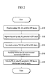
- FIG. 2 is a flowchart showing processes performed by an exemplary apparatus for purifying exhaust gas according to the present invention.
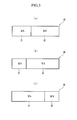
- FIG. 3 is a schematic diagram showing examples of a zone-coated first diesel oxidation catalyst in an exemplary apparatus for purifying exhaust gas according to the present invention.
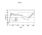
- FIG. 4 is a graph showing temperature in a selective catalytic reduction device according to a lapse of time after beginning of operation of an exemplary apparatus for purifying exhaust gas according to the present invention.
- FIG. 5 is a graph showing exemplary purification efficiency of nitrogen oxide in case 1 according to the present invention.
- FIG. 6 is a graph showing exemplary purification efficiency of nitrogen oxide in case 2 according to the present invention.
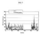
- FIG. 7 is a graph showing exemplary purification efficiency of nitrogen oxide in case 3 according to the present invention.
- FIG. 1 is a block diagram of an apparatus for purifying exhaust gas according to various embodiments of the present invention.
- exhaust gas generated in an engine 10 flows sequentially through a turbo charger 20, a CPF device 30, and a DOC device 40, past a nozzle 50, and through an SCR device 60, and noxious materials contained in the exhaust gas are removed.
- the turbo charger 20, the CPF device 30, the DOC device 40, the nozzle 50, and the SCR device 60 are mounted on an exhaust pipe 70.
- the engine 10 includes a plurality of cylinders for burning an air-fuel mixture. Each cylinder is connected to an intake manifold so as to receive the air-fuel mixture, and the intake manifold is connected to an intake pipe so as to receive fresh air.
- each cylinder is connected to an exhaust manifold, and the exhaust gas generated in a combustion process is gathered in the exhaust manifold.
- the exhaust manifold is connected to the exhaust pipe 70.
- the turbo charger 20 rotates a turbine by using energy of the exhaust gas, and increases an air drawing amount.
- the CPF device 30 is mounted downstream of the turbo charger 20, and includes a first DOC and a catalyst filter (CPF).
- a first DOC and a catalyst filter (CPF).
- CPF catalyst filter
- the first DOC oxidizes HC and CO in the exhaust gas primarily, and oxidizes NO into NO 2 .
- a noble metal including platinum (Pt) and palladium (Pd) is used for the first DOC.
- a ratio of the platinum and the palladium may be 2:1 - 12:1 and a loading amount of the noble metal in the first DOC may be larger than or equal to 35g/ft 3 .
- the first DOC removes the HC and the CO from the exhaust gas primarily, and transmits NO 2 generated therein to the CPF.
- the primary oxidation performed in the first DOC is described in the following Equation 2. 4 ⁇ HC + 3 ⁇ O 2 ⁇ 2 ⁇ CO 2 + 2 ⁇ H 2 ⁇ O 2 ⁇ CO + O 2 ⁇ 2 ⁇ CO 2 2 ⁇ NO + O 2 ⁇ 2 ⁇ NO 2
- the first DOC mainly removes the HC and the CO from the exhaust gas and generates the NO 2 to a degree that is required only for regenerating soot in the CPF as a consequence of the ratio of the platinum and the palladium in the first DOC being controlled to 2:1 - 12:1 and the loading amount of the noble metal in the first DOC being controlled to be larger than or equal to 35g/ft 3 according to various embodiments of the present invention.
- the CPF traps particulate material ("PM") in the exhaust gas and regenerates the trapped PM (i.e., soot).
- Soot regeneration begins when a pressure difference between an inlet and an outlet of the CPF device is larger than or equal to a predetermined pressure (about 20-30 kpa). In this case, soot regeneration of Equation 1 proceeds. Since the CPF device 30 is disposed close to the engine 10 in the apparatus for purifying exhaust gas according to various embodiments of the present invention, it is easy to raise the temperature of the exhaust gas to be higher than or equal to a predetermined temperature required for regenerating the soot, i.e., 300°C. In addition, the NO 2 generated in the first DOC is used for regeneration of the soot.
- the first DOC may be zone-coated in the CPF device 30 in order to enhance efficiency of the primary oxidation, as shown in FIG. 3 . That is, the CPF device 30 includes a first zone-coating portion 31 in which 50-95 wt% of the first DOC is coated, and a second zone-coating portion 32 in which 5-50 wt% of the first DOC is coated. As shown in FIG. 3 , the length ratio of the first zone-coating portion 31 to the second zone-coating portion 32 can be set to any arbitrary value according to performance of the CPF device 30 that one may desire, and may be 2:8 - 7:3.
- the DOC device 40 is mounted downstream of the CPF device 30 and receives the exhaust gas of which the HC and the CO is primarily oxidized and the PM is removed by the CPF device 30.
- a second DOC is coated in the DOC device 40, and secondarily oxidizes the HC and the CO, and oxidizes the NO into the NO 2 .
- a noble metal including platinum and palladium is used for the second DOC.
- a ratio of the platinum and the palladium may be 1:0 - 2:1, and a loading amount of the noble metal in the second DOC may be 10 - 100g/ft 3 .
- the DOC device 40 In order for the NO 2 generated in the DOC device 40 to be sufficiently transmitted to the SCR device 60, the DOC device 40 is directly connected to the SCR device 60.
- the secondary oxidation performed in the second DOC is the same as in Equation 2. Since the ratio of the platinum to the palladium in the second DOC differs from the ratio of the platinum to the palladium in the first DOC, content of oxides generated in the first and second DOCs are different from each other. That is, the first DOC is designed to generate the NO 2 required for soot regeneration, and the second DOC is designed to generate the NO 2 that can be sufficiently supplied to the SCR device 60.
- the nozzle 50 is mounted between the DOC device 40 and the SCR device 60, and doses a reducing agent to the exhaust gas secondarily oxidized in the DOC device 40.
- the reducing agent may be ammonia.
- urea is dosed into the exhaust gas by the nozzle 50 and the urea is decomposed into ammonia.
- the urea is decomposed into ammonia (NH 3 ) by Equation 3.
- the exhaust gas mixed with the reducing agent and the NO 2 generated in the DOC device 40 are transmitted to the SCR device 60.
- the SCR device 60 is mounted downstream of the nozzle 50, and includes a zeolite catalyst where transition elements are ion-exchanged.
- the transition elements may be copper or iron, and a weight ratio of the transition elements to the zeolite may be 1-4.
- the SCR device 60 reduces NO x contained in the exhaust gas into nitrogen gas N 2 by using the NO 2 generated in the DOC device 40 and the reducing agent so as to reduce the NO x amount in the exhaust gas.
- FIG. 2 is a flowchart showing processes performed by an apparatus for purifying exhaust gas according to various embodiments of the present invention.
- the exhaust gas burned in the engine 10 and passing through the turbo charger 20 flows into the CPF device 30, and the CPF device 30 primarily oxidizes the HC, the CO, and the NO in the exhaust gas at step S 110.
- the CPF device 30 regenerates the soot by using the NO 2 contained in the primarily oxidized exhaust gas at step S120.
- the exhaust gas that is primarily oxidized in the CPF device 30 is transmitted to the DOC device 40 through the exhaust pipe 70, and the DOC device 40 secondarily oxidizes the HC, the CO, and the NO contained in the exhaust gas at step S130.
- the loading amount of the noble metal and the ratio of the platinum to the palladium in the DOC device 40 are set so as to sufficiently supply the NO 2 to the SCR device 60.
- the nozzle 50 doses the reducing agent at step S 140 into the exhaust gas that is secondarily oxidized, and the exhaust gas is transmitted to the SCR device 60.
- the SCR device 60 reduces the NO x into the N 2 by using the NO 2 generated in the DOC device 40 and the reducing agent dosed by the nozzle 50 at step S 150.
- the urea can be decomposed by heat at a temperature that is higher than or equal to 156°C, and the NO x can be stably reduced when the temperature in a front portion of the SCR device 60 is higher than or equal to 200°C.
- time for maintaining 200°C that is required for reducing NO x is longest in case 1 and is shortest in case 3. The time is described in Table 2.
- FIG. 5 to FIG. 7 are graphs showing purification efficiency of the NO x in each case according to various embodiments of the present invention.
- the purification efficiency of the NO x in case 1 is slightly improved, compared with the conventional apparatus for purifying exhaust gas.
- the purification efficiencies of the NO x in case 2 and case 3 are largely improved, compared with the conventional apparatus for purifying exhaust gas. Further, the purification efficiency of the NO x in case 3 is more improved than that in case 2.
- the ratio of the NO 2 /NO x is appropriate and performance of the SCR device is guaranteed in a case in which the soot does not exist in the CPF device, but despite the rising exhaust temperature (rising 5°C), the ratio of the NO 2 /NO x decreases from 34.4% to 13.9% and thus the performance of the SCR devices decreases from 70% to 59.8% in a case in which the soot exists in the CPF device according to a conventional art.
- NO 2 generated in a DOC device may be sufficiently supplied to an SCR device as a consequence of directly connecting the DOC device to the SCR device, and thus nitrogen oxide in exhaust gas may be sufficiently reduced.
- HC and CO are primarily oxidized in a CPF device and are secondarily oxidized in the DOC device, the HC and the CO contained in the exhaust gas may be sufficiently removed.
- the CPF device since the CPF device is disposed close to an engine, it may be easy to raise the temperature of the CPF device to a temperature (higher than 300°C) that is required for regenerating soot.
Landscapes
- Chemical & Material Sciences (AREA)
- Engineering & Computer Science (AREA)
- Chemical Kinetics & Catalysis (AREA)
- Combustion & Propulsion (AREA)
- Materials Engineering (AREA)
- Health & Medical Sciences (AREA)
- Organic Chemistry (AREA)
- Mechanical Engineering (AREA)
- General Engineering & Computer Science (AREA)
- Biomedical Technology (AREA)
- Analytical Chemistry (AREA)
- General Chemical & Material Sciences (AREA)
- Oil, Petroleum & Natural Gas (AREA)
- Environmental & Geological Engineering (AREA)
- Toxicology (AREA)
- Crystallography & Structural Chemistry (AREA)
- Exhaust Gas After Treatment (AREA)
- Catalysts (AREA)
- Exhaust Gas Treatment By Means Of Catalyst (AREA)
Abstract
Description
- The present application claims priority to Korean Patent Application No.
10-2008-0029862 filed March 31, 2008 - The present invention relates to an apparatus for purifying exhaust gas of vehicles. More particularly, the present invention relates to an apparatus for purifying exhaust gas that reduces hydrocarbon (HC), carbon monoxide (CO), particulate material (PM), and nitrogen oxide (NOx) contained in the exhaust gas.
- Generally, exhaust gas flowing out through an exhaust manifold from an engine is driven into a catalytic converter mounted at an exhaust pipe and is purified therein. After that, the noise of the exhaust gas is decreased while passing through a muffler and then the exhaust gas is emitted into the air through a tail pipe. The catalytic converter is a type of diesel particulate filter (DPF) and purifies pollutants contained in the exhaust gas. A catalytic carrier for trapping particulate material (PM) contained in the exhaust gas is in the catalytic converter, and the exhaust gas flowing out from the engine is purified through a chemical reaction therein.
- One type of catalytic converter is a selective catalytic reduction (SCR) apparatus. In the selective catalytic reduction (SCR) apparatus, reducing agents such as carbon monoxide and total hydrocarbon (THC) react better with nitrogen oxide than oxygen. Thus, such a catalytic converter is called a selective catalytic reduction apparatus.
- According to a conventional apparatus for reducing nitrogen oxide contained in exhaust gas, a diesel oxidation catalyst (DOC) device oxidizes total hydrocarbon (THC) and carbon monoxide (CO), and oxidizes nitrogen monoxide (NO) into nitrogen dioxide (NO2). After that, an SCR device reduces nitrogen oxides (NOx) into nitrogen gas (N2) by using the NO2 generated in the DOC device and a reducing agent. However, as exhaust gas regeneration (EGR) technology and post injection technology is further applied to vehicles, the THC and the CO contained in exhaust gas increases. In addition, the NO2 generated by oxidizing NO is used in the DOC device when the THC and the CO are oxidized during cool starting. That is, the NO2 is used when the THC and the CO are oxidized at a low temperature.
- In addition, if the NO2 is generated in the DOC device, the NO2 is used for regenerating soot in a catalyzed particulate filter (CPF) device disposed at the rear of the DOC device.
Equation 1 below represents a soot regeneration reaction performed in the CPF device.
- Therefore, it is difficult to reduce the NOx in the exhaust gas according to the conventional apparatus for purifying exhaust gas, since the NO2 generated in the DOC device is firstly used in the CPF device and then a part of the remaining NO2 is supplied to the SCR device.
- In addition, since, by applying the EGR technology and the post injection technology to vehicles, the increased THC and CO are oxidized only in the DOC device, and the THC and the CO are not fully oxidized.
- The information disclosed in this Background of the Invention section is only for enhancement of understanding of the general background of the invention and should not be taken as an acknowledgement or any form of suggestion that this information forms the prior art already known to a person skilled in the art.
- Various aspects of the present invention are directed to provide an apparatus for purifying exhaust gas having advantages of fully oxidizing HC and CO contained in the exhaust gas and sufficiently reducing NOx by causing NO2 generated in the oxidation of the HC and the CO to be sufficiently supplied to an SCR device as a consequence of disposing a DOC device between a CPF device and the SCR device.
- One aspect of the present invention is directed to an apparatus for purifying exhaust gas that may include a catalyzed particulate filter (CPF) device mounted downstream of an engine, the catalyzed particulate filter (CPF) device firstly oxidizing hydrocarbon (HC) and carbon monoxide (CO) in the exhaust gas by using a first diesel oxidation catalyst (DOC), and trapping and regenerating particulate material (PM), a diesel oxidation catalyst (DOC) device mounted downstream of the CPF device, secondarily oxidizing the HC and the CO in the firstly oxidized exhaust gas by using a second DOC, and oxidizing nitrogen monoxide (NO) into nitrogen dioxide (NO2) by using the second DOC, a nozzle mounted downstream of the DOC device, and dosing a reducing agent to exhaust gas secondarily oxidized by the DOC device, and/or a selective catalytic reduction (SCR) device mounted downstream of the nozzle, and reducing nitrogen oxide (NOx) in the exhaust gas into nitrogen gas (N2) by using the NO2 generated in the DOC device and the reducing agent.
- The regeneration of the particulate material (PM) may begin when a pressure difference between an inlet and an outlet of the CPF device is larger than or equal to a predetermined pressure. The predetermined pressure may be between approximately 20 kpa and approximately 30 kpa.
- The first DOC may include a noble metal. The noble metal may include platinum (Pt) and palladium (Pd). A ratio of the platinum to the palladium may be approximately 2:1 to approximately 12:1. A loading amount of the noble metal in the first DOC may be larger than or equal to 35g/ft3.
- The second DOC may include a noble metal. The noble metal may include platinum and palladium. A ratio of the platinum to the palladium may be approximately 1:0 to approximately 2:1. A loading amount of the noble metal in the second DOC may be between approximately 10 100g/ft3 and approximately 100g/ft3.
- The first DOC may oxidize nitrogen monoxide (NO) into the nitrogen dioxide (NO2), and the oxidized nitrogen dioxide may be used for regenerating the particulate material (PM).
- The SCR device may include a zeolite-catalyst where transition elements are ion-exchanged. A weight ratio of the transition elements to the zeolite may be approximately 1:4. The transition elements may be copper or iron.
- The CPF device may include a first zone-coating portion in which 50-95 wt% of the first DOC is coated, and/or a second zone-coating portion in which 5-50 wt% of the first DOC is coated. Length ratio of the first zone-coating portion to the second zone-coating portion may be between approximately 2:8 and approximately 7:3.
- The reducing agent may be ammonia.
- The methods and apparatuses of the present invention have other features and advantages which will be apparent from or are set forth in more detail in the accompanying drawings, which are incorporated herein, and the following Detailed Description of the Invention, which together serve to explain certain principles of the present invention.
-
FIG. 1 is a block diagram of an exemplary apparatus for purifying exhaust gas according to the present invention. -
FIG. 2 is a flowchart showing processes performed by an exemplary apparatus for purifying exhaust gas according to the present invention. -
FIG. 3 is a schematic diagram showing examples of a zone-coated first diesel oxidation catalyst in an exemplary apparatus for purifying exhaust gas according to the present invention. -
FIG. 4 is a graph showing temperature in a selective catalytic reduction device according to a lapse of time after beginning of operation of an exemplary apparatus for purifying exhaust gas according to the present invention. -
FIG. 5 is a graph showing exemplary purification efficiency of nitrogen oxide incase 1 according to the present invention. -
FIG. 6 is a graph showing exemplary purification efficiency of nitrogen oxide incase 2 according to the present invention. -
FIG. 7 is a graph showing exemplary purification efficiency of nitrogen oxide incase 3 according to the present invention. - Reference will now be made in detail to various embodiments of the present invention(s), examples of which are illustrated in the accompanying drawings and described below. While the invention(s) will be described in conjunction with exemplary embodiments, it will be understood that present description is not intended to limit the invention(s) to those exemplary embodiments. On the contrary, the invention(s) is/are intended to cover not only the exemplary embodiments, but also various alternatives, modifications, equivalents and other embodiments, which may be included within the spirit and scope of the invention as defined by the appended claims.
-
FIG. 1 is a block diagram of an apparatus for purifying exhaust gas according to various embodiments of the present invention. - As shown in
FIG. 1 , exhaust gas generated in anengine 10 flows sequentially through aturbo charger 20, aCPF device 30, and aDOC device 40, past anozzle 50, and through anSCR device 60, and noxious materials contained in the exhaust gas are removed. Theturbo charger 20, theCPF device 30, theDOC device 40, thenozzle 50, and theSCR device 60 are mounted on anexhaust pipe 70. - The
engine 10 includes a plurality of cylinders for burning an air-fuel mixture.
Each cylinder is connected to an intake manifold so as to receive the air-fuel mixture, and the intake manifold is connected to an intake pipe so as to receive fresh air. - In addition, each cylinder is connected to an exhaust manifold, and the exhaust gas generated in a combustion process is gathered in the exhaust manifold. The exhaust manifold is connected to the
exhaust pipe 70. - The
turbo charger 20 rotates a turbine by using energy of the exhaust gas, and increases an air drawing amount. - The
CPF device 30 is mounted downstream of theturbo charger 20, and includes a first DOC and a catalyst filter (CPF). - The first DOC oxidizes HC and CO in the exhaust gas primarily, and oxidizes NO into NO2. A noble metal including platinum (Pt) and palladium (Pd) is used for the first DOC. In order to effectively perform the first oxidation, a ratio of the platinum and the palladium may be 2:1 - 12:1 and a loading amount of the noble metal in the first DOC may be larger than or equal to 35g/ft3. The first DOC removes the HC and the CO from the exhaust gas primarily, and transmits NO2 generated therein to the CPF. The primary oxidation performed in the first DOC is described in the following
Equation 2.
- The first DOC mainly removes the HC and the CO from the exhaust gas and generates the NO2 to a degree that is required only for regenerating soot in the CPF as a consequence of the ratio of the platinum and the palladium in the first DOC being controlled to 2:1 - 12:1 and the loading amount of the noble metal in the first DOC being controlled to be larger than or equal to 35g/ft3 according to various embodiments of the present invention.
- The CPF traps particulate material ("PM") in the exhaust gas and regenerates the trapped PM (i.e., soot). Soot regeneration begins when a pressure difference between an inlet and an outlet of the CPF device is larger than or equal to a predetermined pressure (about 20-30 kpa). In this case, soot regeneration of
Equation 1 proceeds. Since theCPF device 30 is disposed close to theengine 10 in the apparatus for purifying exhaust gas according to various embodiments of the present invention, it is easy to raise the temperature of the exhaust gas to be higher than or equal to a predetermined temperature required for regenerating the soot, i.e., 300°C. In addition, the NO2 generated in the first DOC is used for regeneration of the soot. - Since the soot is accumulated at a rear portion of the
CPF device 30, the primary oxidation hardly occurs at the rear portion of theCPF device 30. Therefore, the first DOC may be zone-coated in theCPF device 30 in order to enhance efficiency of the primary oxidation, as shown inFIG. 3 . That is, theCPF device 30 includes a first zone-coatingportion 31 in which 50-95 wt% of the first DOC is coated, and a second zone-coatingportion 32 in which 5-50 wt% of the first DOC is coated. As shown inFIG. 3 , the length ratio of the first zone-coatingportion 31 to the second zone-coatingportion 32 can be set to any arbitrary value according to performance of theCPF device 30 that one may desire, and may be 2:8 - 7:3. - The
DOC device 40 is mounted downstream of theCPF device 30 and receives the exhaust gas of which the HC and the CO is primarily oxidized and the PM is removed by theCPF device 30. A second DOC is coated in theDOC device 40, and secondarily oxidizes the HC and the CO, and oxidizes the NO into the NO2. In order to effectively generate the NO2, a noble metal including platinum and palladium is used for the second DOC. A ratio of the platinum and the palladium may be 1:0 - 2:1, and a loading amount of the noble metal in the second DOC may be 10 - 100g/ft3. - In order for the NO2 generated in the
DOC device 40 to be sufficiently transmitted to theSCR device 60, theDOC device 40 is directly connected to theSCR device 60. The secondary oxidation performed in the second DOC is the same as inEquation 2. Since the ratio of the platinum to the palladium in the second DOC differs from the ratio of the platinum to the palladium in the first DOC, content of oxides generated in the first and second DOCs are different from each other. That is, the first DOC is designed to generate the NO2 required for soot regeneration, and the second DOC is designed to generate the NO2 that can be sufficiently supplied to theSCR device 60. - The
nozzle 50 is mounted between theDOC device 40 and theSCR device 60, and doses a reducing agent to the exhaust gas secondarily oxidized in theDOC device 40. The reducing agent may be ammonia. Generally, urea is dosed into the exhaust gas by thenozzle 50 and the urea is decomposed into ammonia. - That is, the urea is decomposed into ammonia (NH3) by
Equation 3.
- The exhaust gas mixed with the reducing agent and the NO2 generated in the
DOC device 40 are transmitted to theSCR device 60. - The
SCR device 60 is mounted downstream of thenozzle 50, and includes a zeolite catalyst where transition elements are ion-exchanged. In order to effectively reduce the NOx, the transition elements may be copper or iron, and a weight ratio of the transition elements to the zeolite may be 1-4. TheSCR device 60 reduces NOx contained in the exhaust gas into nitrogen gas N2 by using the NO2 generated in theDOC device 40 and the reducing agent so as to reduce the NOx amount in the exhaust gas. - The reaction performed in the
SCR device 60 is described Equation 4 below.
- Hereinafter, operations of the apparatus for purifying exhaust gas according to various embodiments of the present invention will be described in detail.
-
FIG. 2 is a flowchart showing processes performed by an apparatus for purifying exhaust gas according to various embodiments of the present invention. - As shown in
FIG. 2 , the exhaust gas burned in theengine 10 and passing through theturbo charger 20 flows into theCPF device 30, and theCPF device 30 primarily oxidizes the HC, the CO, and the NO in the exhaust gas atstep S 110. - In addition, the
CPF device 30 regenerates the soot by using the NO2 contained in the primarily oxidized exhaust gas at step S120. - The exhaust gas that is primarily oxidized in the
CPF device 30 is transmitted to theDOC device 40 through theexhaust pipe 70, and theDOC device 40 secondarily oxidizes the HC, the CO, and the NO contained in the exhaust gas at step S130. The loading amount of the noble metal and the ratio of the platinum to the palladium in theDOC device 40 are set so as to sufficiently supply the NO2 to theSCR device 60. - After that, the
nozzle 50 doses the reducing agent at step S 140 into the exhaust gas that is secondarily oxidized, and the exhaust gas is transmitted to theSCR device 60. - The
SCR device 60 reduces the NOx into the N2 by using the NO2 generated in theDOC device 40 and the reducing agent dosed by thenozzle 50 atstep S 150. - Experiments have been performed regarding three cases having different loading amounts of the noble metal and ratio of the platinum to the palladium in the first DOC and the second DOC, and the loading amounts of the noble metal and the ratio of the platinum to the palladium in the first DOC and the second DOC are described in the following Table 1 fore each case. Here, volumes of the
CPF device 30, theDOC device 40, and theSCR device 60 for a 3ℓ engine are 3.5ℓ, 1.3ℓ, and 5ℓ, respectively.Table 1 Case 1Case 2Case 3First DOC 50 g/ft3(Pt/Pd=6/1) 35 g/ft3(Pt/Pd=2/1) 55 g/ft3(Pt/Pd=2/1) Second DOC 110 g/ft3(Pt/Pd=2/1) 140 g/ft3(Pt/Pd=2/1) 60 g/ft3(Pt/Pd=1/0) SCR Fe-Zeolite Fe-Zeolite Fe-Zeolite - Generally, the urea can be decomposed by heat at a temperature that is higher than or equal to 156°C, and the NOx can be stably reduced when the temperature in a front portion of the
SCR device 60 is higher than or equal to 200°C. As shown inFIG. 4 , time for maintaining 200°C that is required for reducing NOx is longest incase 1 and is shortest incase 3. The time is described in Table 2.Table 2 Case 1Case 2Case 3Time for maintaining 200°C (second) 1371 923 348 - In addition, purification efficiencies of the CO, the HC, and the NOx are described in Table 3.
Table 3 List Case 1 Case 2Case 3CPF device + DOC device NO2/NOx ratio Downstream of engine 32% 32% 32% Downstream of CPF device 12% 16% 19% Downstream of DOC device 26% 47% 35% Slip amount of HC 6.3g 4.8g 2.5g SCR device Time required for reaching 200°C at front portion of SCR device (second) 285 363 296 Time for maintaining 200°C (second) 1371 923 348 Absorption amount of HC 4.4g 4.0g 1.3g Purification efficiencies of CO/HC (%) 75/85 75/87 83/89 Purification efficiency of NOx(%) 26 44 54 - As shown in Table 3, temperature conditions and NO2/NOx ratios in the SCR device in
case 2 are better than those incase 3. However, the slip amount of the HC in theCPF device 30 and theDOC device 40 is large incase 2, and thus performance of theSCR device 60 is suppressed. Therefore, the purification efficiencies of the CO/HC and the purification efficiency of the NOx are best incase 3. In addition, since the loading amount of the noble metal is smallest incase 3, the manufacturing cost of the apparatus for purifying exhaust gas is also smallest incase 3. -
FIG. 5 to FIG. 7 are graphs showing purification efficiency of the NOx in each case according to various embodiments of the present invention. - As shown in
FIG. 5 , the purification efficiency of the NOx incase 1 is slightly improved, compared with the conventional apparatus for purifying exhaust gas. As shown inFIG. 6 andFIG. 7 , the purification efficiencies of the NOx incase 2 andcase 3 are largely improved, compared with the conventional apparatus for purifying exhaust gas. Further, the purification efficiency of the NOx incase 3 is more improved than that incase 2. - As shown in the following Table 4, the ratio of the NO2/NOx is appropriate and performance of the SCR device is guaranteed in a case in which the soot does not exist in the CPF device, but despite the rising exhaust temperature (rising 5°C), the ratio of the NO2/NOx decreases from 34.4% to 13.9% and thus the performance of the SCR devices decreases from 70% to 59.8% in a case in which the soot exists in the CPF device according to a conventional art.
- As shown in the following Table 5, exhaust temperature rises by 10°C at an outlet of the DOC device because of oxidation performance, and the ratio of the NO2/NOx increases from 34.8% to 37.2% according to various embodiments of the present invention. Therefore, the ratio of the NO2/NOx may be stably maintained or increased, and thus the performance of the SCR device increases from 63.5% to 69.7%. Table 4 and Table 5 are compared based on the same catalyst cost.
Table 4 -- Conventional art: DOC device (110g/ft3, Pt/Pd=2/1) + CPF device (35g/ft3, Pt/Pd=6/1) + DM (nozzle) + SCR device Soot loading Outlet of turbo charger Outlet of DOC device Outlet of SCR device NO2/NOx CO HC NO2/NOx CO HC NOx w/ o soot 32 94.2 93.6 34.4 93.2 94.3 70.0 w/soot (10g/L) 32 95.1 93.3 13.9 94.8 94.6 59.8 Table 5 -- Exemplary embodiments of the present invention: CPF device (55g/ft3, Pt/Pd=2/1) + DOC device (60g/ft3, Pt/Pd=1/0) + DM (nozzle) + SCR device Soot loading Outlet of turbo charger Outlet of DOC device Outlet of SCR device NO2/NOx CO HC NO2/NOx CO HC NOx w/ o soot 32 82.7 81.7 34.8 82.0 89.8 63.5 w/soot (10g/L) 32 85.1 82.8 37.2 86.8 91.8 69.7 - According to the present invention, NO2 generated in a DOC device may be sufficiently supplied to an SCR device as a consequence of directly connecting the DOC device to the SCR device, and thus nitrogen oxide in exhaust gas may be sufficiently reduced.
- Since HC and CO are primarily oxidized in a CPF device and are secondarily oxidized in the DOC device, the HC and the CO contained in the exhaust gas may be sufficiently removed.
- Further, since the CPF device is disposed close to an engine, it may be easy to raise the temperature of the CPF device to a temperature (higher than 300°C) that is required for regenerating soot.
- For convenience in explanation and accurate definition in the appended claims, the terms "front" or "rear", and etc. are used to describe features of the exemplary embodiments with reference to the positions of such features as displayed in the figures.
- The foregoing descriptions of specific exemplary embodiments of the present invention have been presented for purposes of illustration and description. They are not intended to be exhaustive or to limit the invention to the precise forms disclosed, and obviously many modifications and variations are possible in light of the above teachings. The exemplary embodiments were chosen and described in order to explain certain principles of the invention and their practical application, to thereby enable others skilled in the art to make and utilize various exemplary embodiments of the present invention, as well as various alternatives and modifications thereof. It is intended that the scope of the invention be defined by the Claims appended hereto and their equivalents.
Claims (15)
- An apparatus for purifying exhaust gas, comprising:a catalyzed particulate filter (CPF) device mounted downstream of an engine, the catalyzed particulate filter (CPF) device firstly oxidizing hydrocarbon (HC) and carbon monoxide (CO) in the exhaust gas by using a first diesel oxidation catalyst (DOC), and trapping and regenerating particulate material (PM);a diesel oxidation catalyst (DOC) device mounted downstream of the CPF device, secondarily oxidizing the HC and the CO in the firstly oxidized exhaust gas by using a second DOC, and oxidizing nitrogen monoxide (NO) into nitrogen dioxide (NO2) by using the second DOC;a nozzle mounted downstream of the DOC device, and dosing a reducing agent to exhaust gas secondarily oxidized by the DOC device; anda selective catalytic reduction (SCR) device mounted downstream of the nozzle, and reducing nitrogen oxide (NOx) in the exhaust gas into nitrogen gas (N2) by using the NO2 generated in the DOC device and the reducing agent.
- The apparatus of claim 1, wherein the regeneration of the particulate material (PM) begins when a pressure difference between an inlet and an outlet of the CPF device is larger than or equal to a predetermined pressure.
- The apparatus of claim 2, wherein the predetermined pressure is between approximately 20 kpa and approximately 30 kpa.
- The apparatus of claim 1, wherein the first DOC and/or the second DOC comprises a noble metal.
- The apparatus of claim 4, wherein the noble metal comprises platinum (Pt) and palladium (Pd).
- The apparatus of claim 5, wherein a ratio of the platinum to the palladium of the noble metal in the first DOC is approximately 2:1 to approximately 12:1, and/or wherein a ratio of the platinum to the palladium of the noble metal in the second DOC is approximately 1:0 to approximately 2:1.
- The apparatus of claim 5, wherein a loading amount of the noble metal in the first DOC is larger than or equal to 35g/ft3, and/or wherein a loading amount of the noble metal in the second DOC is between approximately 10 100g/ft3 and approximately 100g/ft3.
- The apparatus of claim 1, wherein the first DOC oxidizes nitrogen monoxide (NO) into the nitrogen dioxide (NO2), and the oxidized nitrogen dioxide is used for regenerating the particulate material (PM).
- The apparatus of claim 1, wherein the SCR device comprises a zeolite-catalyst where transition elements are ion-exchanged.
- The apparatus of claim 9, wherein a weight ratio of the transition elements to the zeolite is approximately 1:4.
- The apparatus of claim 9, wherein the transition elements are copper or iron.
- The apparatus of claim 1, wherein the CPF device comprises:a first zone-coating portion in which 50-95 wt% of the first DOC is coated; anda second zone-coating portion in which 5-50 wt% of the first DOC is coated.
- The apparatus of claim 12, wherein length ratio of the first zone-coating portion to the second zone-coating portion is between approximately 2:8 and approximately 7:3.
- The apparatus of claim 1, wherein the reducing agent is ammonia.
- An engine comprising the apparatus for purifying exhaust gas as defined in claim 1.
Applications Claiming Priority (1)
| Application Number | Priority Date | Filing Date | Title |
|---|---|---|---|
| KR1020080029862A KR100969378B1 (en) | 2008-03-31 | 2008-03-31 | Exhaust gas filter |
Publications (2)
| Publication Number | Publication Date |
|---|---|
| EP2106841A1 true EP2106841A1 (en) | 2009-10-07 |
| EP2106841B1 EP2106841B1 (en) | 2012-01-25 |
Family
ID=40085414
Family Applications (1)
| Application Number | Title | Priority Date | Filing Date |
|---|---|---|---|
| EP08168838A Not-in-force EP2106841B1 (en) | 2008-03-31 | 2008-11-11 | Apparatus for purifying exhaust gas |
Country Status (4)
| Country | Link |
|---|---|
| US (1) | US8402754B2 (en) |
| EP (1) | EP2106841B1 (en) |
| KR (1) | KR100969378B1 (en) |
| CN (1) | CN101550859B (en) |
Cited By (6)
| Publication number | Priority date | Publication date | Assignee | Title |
|---|---|---|---|---|
| WO2011061321A1 (en) * | 2009-11-20 | 2011-05-26 | Basf Se | Zoned catalyzed soot filter |
| GB2481057A (en) * | 2010-06-11 | 2011-12-14 | Johnson Matthey Plc | Exhaust system comprising a catalyst with a downstream filter and SCR catalyst |
| FR2970292A1 (en) * | 2011-01-11 | 2012-07-13 | Peugeot Citroen Automobiles Sa | Particle filter for use in exhaust line of diesel engine, has catalytic coating including catalysts for reduction of nitrogen oxides, where concentration of catalysts is higher in upstream portion than that of downstream portion of filter |
| GB2521425A (en) * | 2013-12-19 | 2015-06-24 | Gm Global Tech Operations Inc | Exhaust system for a diesel engine |
| US9636634B2 (en) | 2014-01-23 | 2017-05-02 | Johnson Matthey Public Limited Company | Diesel oxidation catalyst and exhaust system |
| EP2922631B1 (en) | 2012-11-21 | 2018-05-16 | Johnson Matthey Public Limited Company | Catalysed soot filter for treating the exhaust gas of a compression ignition engine |
Families Citing this family (13)
| Publication number | Priority date | Publication date | Assignee | Title |
|---|---|---|---|---|
| US8800268B2 (en) * | 2006-12-01 | 2014-08-12 | Basf Corporation | Zone coated filter, emission treatment systems and methods |
| KR101637259B1 (en) * | 2010-07-06 | 2016-07-07 | 현대자동차 주식회사 | Oxidation catalyst |
| US9528413B2 (en) * | 2010-07-30 | 2016-12-27 | Ford Global Technologies, Llc | Synergistic SCR/DOC configurations for lowering diesel emissions |
| US8062601B2 (en) * | 2010-10-26 | 2011-11-22 | Ford Global Technologies, Llc | Emission SCR NOX aftertreatment system having reduced SO3 generation and improved durability |
| KR20120095747A (en) | 2011-02-21 | 2012-08-29 | 한국에너지기술연구원 | Multi-functional particulate filter and exhaust gas filtering device using this |
| GB2490522A (en) * | 2011-05-04 | 2012-11-07 | T Baden Hardstaff Ltd | Exhaust system for a dual fuel engine |
| KR101305198B1 (en) * | 2011-12-09 | 2013-09-26 | 현대자동차주식회사 | Particulate matters sensor unit |
| JP5884920B2 (en) * | 2012-11-16 | 2016-03-15 | トヨタ自動車株式会社 | Exhaust gas purification system for internal combustion engine |
| DE102014001880A1 (en) * | 2014-02-14 | 2015-08-20 | Deutz Aktiengesellschaft | Process for cleaning diesel engine exhaust |
| KR102107657B1 (en) * | 2014-07-22 | 2020-05-07 | 두산인프라코어 주식회사 | Exhaust gas cleaning device |
| CN107376720B (en) * | 2017-07-26 | 2018-06-19 | 深圳市市政工程总公司 | A kind of multi-function dust remover |
| JP7264798B2 (en) * | 2019-06-28 | 2023-04-25 | 株式会社クボタ | engine |
| KR102313238B1 (en) | 2021-08-31 | 2021-10-14 | 화이버텍 (주) | Heater for the exhaust gas reduction apparatus for the vehicles and exhaust gas reduction apparatus for the vehicles using the same |
Citations (7)
| Publication number | Priority date | Publication date | Assignee | Title |
|---|---|---|---|---|
| EP0393917A2 (en) * | 1989-04-20 | 1990-10-24 | Engelhard Corporation | Method for reduction of nitrogen oxides with ammonia using promoted zeolite catalysts |
| WO2002014657A1 (en) * | 2000-08-15 | 2002-02-21 | Engelhard Corporation | Exhaust system for enhanced reduction of nitrogen oxides and particulates from diesel engines |
| DE102004040549A1 (en) | 2004-08-21 | 2006-02-23 | Umicore Ag & Co. Kg | Catalytically coated particle filter and process for its preparation and its use |
| US20060057046A1 (en) * | 2004-09-14 | 2006-03-16 | Punke Alfred H | Pressure-balanced, catalyzed soot filter |
| EP1728984A2 (en) | 2005-05-30 | 2006-12-06 | J. Eberspächer GmbH & Co. KG | Exhaust system |
| WO2007136753A2 (en) | 2006-05-18 | 2007-11-29 | Clean Diesel Technologies, Inc. | Improvements in diesel particulate control |
| WO2008121167A1 (en) * | 2006-12-01 | 2008-10-09 | Basf Catalysts Llc | Zone coated filter, emission treatment systems and methods |
Family Cites Families (18)
| Publication number | Priority date | Publication date | Assignee | Title |
|---|---|---|---|---|
| DE69216101T2 (en) * | 1992-05-13 | 1997-07-17 | Sumitomo Electric Industries | PARTICLE FILTER FOR PURIFYING DIESEL ENGINE EXHAUST GAS |
| GB9802504D0 (en) * | 1998-02-06 | 1998-04-01 | Johnson Matthey Plc | Improvements in emission control |
| EP1458960B1 (en) * | 2001-12-20 | 2011-02-09 | Johnson Matthey Public Limited Company | Improvements in selective catalytic reduction |
| KR101225517B1 (en) * | 2002-09-13 | 2013-01-23 | 존슨 맛쎄이 퍼블릭 리미티드 컴파니 | Compression ignition engine and exhaust system therefor |
| JP2004138022A (en) * | 2002-10-21 | 2004-05-13 | Babcock Hitachi Kk | Method of and device for treating diesel exhaust gas |
| US6928806B2 (en) * | 2002-11-21 | 2005-08-16 | Ford Global Technologies, Llc | Exhaust gas aftertreatment systems |
| DE10300298A1 (en) * | 2003-01-02 | 2004-07-15 | Daimlerchrysler Ag | Exhaust gas aftertreatment device and method |
| GB0304939D0 (en) * | 2003-03-05 | 2003-04-09 | Johnson Matthey Plc | Light-duty diesel engine and a particulate filter therefor |
| SE526680C2 (en) * | 2003-12-31 | 2005-10-25 | Abb Ab | Procedure for reducing noise in a high-power internal combustion engine |
| JP2005226458A (en) * | 2004-02-10 | 2005-08-25 | Babcock Hitachi Kk | Method and device for treating diesel exhaust gas |
| JP2005248787A (en) * | 2004-03-03 | 2005-09-15 | Mitsubishi Fuso Truck & Bus Corp | Exhaust cleaner |
| KR100860327B1 (en) * | 2004-04-12 | 2008-09-25 | 도요다 지도샤 가부시끼가이샤 | Exhaust gas purifying apparatus |
| EP1755778A1 (en) * | 2004-04-26 | 2007-02-28 | HTE Aktiengesellschaft The High Throughput Experimentation Company | Catalysts for the simultaneous removal of carbon monoxide and hydrocarbons from oxygen-rich exhaust gases and processes for the manufacture thereof |
| US7501105B2 (en) * | 2004-07-29 | 2009-03-10 | N.E. Chemcat Corporation | NOx reduction catalyst having excellent low-temperature characteristics |
| KR100680184B1 (en) | 2005-07-06 | 2007-02-07 | 희성엥겔하드주식회사 | Diesel Engine Soot Filter |
| KR100680792B1 (en) * | 2005-12-09 | 2007-02-08 | 현대자동차주식회사 | Regeneration control method and apparatus of NOX-PM simultaneous reduction apparatus equipped with nitrogen oxide removal catalyst and catalyst filtration apparatus |
| US7740809B2 (en) * | 2006-02-15 | 2010-06-22 | Hitachi Metals, Ltd. | Exhaust gas-cleaning apparatus |
| JP2007285295A (en) | 2006-03-24 | 2007-11-01 | Ngk Insulators Ltd | Exhaust emission control system |
-
2008
- 2008-03-31 KR KR1020080029862A patent/KR100969378B1/en not_active Expired - Fee Related
- 2008-11-11 EP EP08168838A patent/EP2106841B1/en not_active Not-in-force
- 2008-11-21 US US12/276,214 patent/US8402754B2/en not_active Expired - Fee Related
- 2008-11-27 CN CN2008101790774A patent/CN101550859B/en not_active Expired - Fee Related
Patent Citations (7)
| Publication number | Priority date | Publication date | Assignee | Title |
|---|---|---|---|---|
| EP0393917A2 (en) * | 1989-04-20 | 1990-10-24 | Engelhard Corporation | Method for reduction of nitrogen oxides with ammonia using promoted zeolite catalysts |
| WO2002014657A1 (en) * | 2000-08-15 | 2002-02-21 | Engelhard Corporation | Exhaust system for enhanced reduction of nitrogen oxides and particulates from diesel engines |
| DE102004040549A1 (en) | 2004-08-21 | 2006-02-23 | Umicore Ag & Co. Kg | Catalytically coated particle filter and process for its preparation and its use |
| US20060057046A1 (en) * | 2004-09-14 | 2006-03-16 | Punke Alfred H | Pressure-balanced, catalyzed soot filter |
| EP1728984A2 (en) | 2005-05-30 | 2006-12-06 | J. Eberspächer GmbH & Co. KG | Exhaust system |
| WO2007136753A2 (en) | 2006-05-18 | 2007-11-29 | Clean Diesel Technologies, Inc. | Improvements in diesel particulate control |
| WO2008121167A1 (en) * | 2006-12-01 | 2008-10-09 | Basf Catalysts Llc | Zone coated filter, emission treatment systems and methods |
Cited By (11)
| Publication number | Priority date | Publication date | Assignee | Title |
|---|---|---|---|---|
| WO2011061321A1 (en) * | 2009-11-20 | 2011-05-26 | Basf Se | Zoned catalyzed soot filter |
| US8802016B2 (en) | 2009-11-20 | 2014-08-12 | BASF Catalyst Germany GmbH | Zoned catalyzed soot filter |
| GB2481057A (en) * | 2010-06-11 | 2011-12-14 | Johnson Matthey Plc | Exhaust system comprising a catalyst with a downstream filter and SCR catalyst |
| FR2970292A1 (en) * | 2011-01-11 | 2012-07-13 | Peugeot Citroen Automobiles Sa | Particle filter for use in exhaust line of diesel engine, has catalytic coating including catalysts for reduction of nitrogen oxides, where concentration of catalysts is higher in upstream portion than that of downstream portion of filter |
| EP2922631B1 (en) | 2012-11-21 | 2018-05-16 | Johnson Matthey Public Limited Company | Catalysed soot filter for treating the exhaust gas of a compression ignition engine |
| EP2922631B2 (en) † | 2012-11-21 | 2021-12-01 | Johnson Matthey Public Limited Company | Catalysed soot filter for treating the exhaust gas of a compression ignition engine |
| GB2521425A (en) * | 2013-12-19 | 2015-06-24 | Gm Global Tech Operations Inc | Exhaust system for a diesel engine |
| US9636634B2 (en) | 2014-01-23 | 2017-05-02 | Johnson Matthey Public Limited Company | Diesel oxidation catalyst and exhaust system |
| US9849423B2 (en) | 2014-01-23 | 2017-12-26 | Johnson Matthey Public Limited Company | Diesel oxidation catalyst and exhaust system |
| US10286359B2 (en) | 2014-01-23 | 2019-05-14 | Johnson Matthey Public Limited Company | Diesel oxidation catalyst and exhaust system |
| US11167246B2 (en) | 2014-01-23 | 2021-11-09 | Johnson Matthey Public Limited Company | Diesel oxidation catalyst and exhaust system |
Also Published As
| Publication number | Publication date |
|---|---|
| CN101550859A (en) | 2009-10-07 |
| KR100969378B1 (en) | 2010-07-09 |
| US20090241521A1 (en) | 2009-10-01 |
| CN101550859B (en) | 2013-06-05 |
| EP2106841B1 (en) | 2012-01-25 |
| US8402754B2 (en) | 2013-03-26 |
| KR20090104441A (en) | 2009-10-06 |
Similar Documents
| Publication | Publication Date | Title |
|---|---|---|
| EP2106841B1 (en) | Apparatus for purifying exhaust gas | |
| US8168125B2 (en) | Diesel oxidation catalyst and exhaust system provided with the same | |
| EP1458960B1 (en) | Improvements in selective catalytic reduction | |
| JP6450540B2 (en) | Lean burn IC engine exhaust system | |
| CN101979847B (en) | Exhaust gas treatment system including HC-SCR and two-way catalyst and method of using same | |
| JP6423624B2 (en) | Method for reducing nitrogen oxides in diesel engine exhaust gas and exhaust gas aftertreatment system for carrying out the method | |
| KR101986388B1 (en) | Exhaust system having ammonia slip catalyst in egr circuit | |
| EP2230001A1 (en) | Exhaust gas treatment | |
| JP6396636B2 (en) | Improved exhaust gas control | |
| US8128880B2 (en) | NOx reduction catalyst and exhaust system using the same | |
| US20090151341A1 (en) | Apparatus for reducing nitrogen oxide contained in exhaust gas | |
| US8327624B2 (en) | System for purifying exhaust gas | |
| CN101979846A (en) | Exhaust gas treatment system including lean NOx trap and binary catalyst and method of use | |
| US8677740B2 (en) | Method for predicting regeneration of DeNOx catalyst and exhaust system using the same | |
| CN107489506B (en) | Combination system of distributed solid SSCR system and ASC catalyst | |
| US10287939B2 (en) | Exhaust gas after-treatment unit for an internal combustion engine | |
| EP2292316A1 (en) | Apparatus for after-treatment of exhaust from diesel engine | |
| US20170276053A1 (en) | After-Treatment System | |
| US20140134062A1 (en) | Exhaust gas purification system of vehicle | |
| KR102750538B1 (en) | Exhaust gas post processing apparatus | |
| US20100154392A1 (en) | Adjusting nitrogen oxide ratios in exhaust gas | |
| CN120845158B (en) | Be used for reducing diesel engine N2O emission post-treatment method and system | |
| WO2018057170A1 (en) | After-treatment system |
Legal Events
| Date | Code | Title | Description |
|---|---|---|---|
| PUAI | Public reference made under article 153(3) epc to a published international application that has entered the european phase |
Free format text: ORIGINAL CODE: 0009012 |
|
| AK | Designated contracting states |
Kind code of ref document: A1 Designated state(s): AT BE BG CH CY CZ DE DK EE ES FI FR GB GR HR HU IE IS IT LI LT LU LV MC MT NL NO PL PT RO SE SI SK TR |
|
| AX | Request for extension of the european patent |
Extension state: AL BA MK RS |
|
| 17P | Request for examination filed |
Effective date: 20100129 |
|
| 17Q | First examination report despatched |
Effective date: 20100222 |
|
| AKX | Designation fees paid |
Designated state(s): DE FR GB |
|
| GRAP | Despatch of communication of intention to grant a patent |
Free format text: ORIGINAL CODE: EPIDOSNIGR1 |
|
| GRAS | Grant fee paid |
Free format text: ORIGINAL CODE: EPIDOSNIGR3 |
|
| GRAA | (expected) grant |
Free format text: ORIGINAL CODE: 0009210 |
|
| AK | Designated contracting states |
Kind code of ref document: B1 Designated state(s): DE FR GB |
|
| REG | Reference to a national code |
Ref country code: GB Ref legal event code: FG4D |
|
| REG | Reference to a national code |
Ref country code: DE Ref legal event code: R096 Ref document number: 602008012846 Country of ref document: DE Effective date: 20120322 |
|
| PLBE | No opposition filed within time limit |
Free format text: ORIGINAL CODE: 0009261 |
|
| STAA | Information on the status of an ep patent application or granted ep patent |
Free format text: STATUS: NO OPPOSITION FILED WITHIN TIME LIMIT |
|
| 26N | No opposition filed |
Effective date: 20121026 |
|
| REG | Reference to a national code |
Ref country code: DE Ref legal event code: R097 Ref document number: 602008012846 Country of ref document: DE Effective date: 20121026 |
|
| GBPC | Gb: european patent ceased through non-payment of renewal fee |
Effective date: 20121111 |
|
| PG25 | Lapsed in a contracting state [announced via postgrant information from national office to epo] |
Ref country code: GB Free format text: LAPSE BECAUSE OF NON-PAYMENT OF DUE FEES Effective date: 20121111 |
|
| REG | Reference to a national code |
Ref country code: FR Ref legal event code: PLFP Year of fee payment: 8 |
|
| REG | Reference to a national code |
Ref country code: FR Ref legal event code: PLFP Year of fee payment: 9 |
|
| REG | Reference to a national code |
Ref country code: FR Ref legal event code: PLFP Year of fee payment: 10 |
|
| REG | Reference to a national code |
Ref country code: FR Ref legal event code: PLFP Year of fee payment: 11 |
|
| PGFP | Annual fee paid to national office [announced via postgrant information from national office to epo] |
Ref country code: DE Payment date: 20181022 Year of fee payment: 11 |
|
| PGFP | Annual fee paid to national office [announced via postgrant information from national office to epo] |
Ref country code: FR Payment date: 20181029 Year of fee payment: 11 |
|
| REG | Reference to a national code |
Ref country code: DE Ref legal event code: R119 Ref document number: 602008012846 Country of ref document: DE |
|
| PG25 | Lapsed in a contracting state [announced via postgrant information from national office to epo] |
Ref country code: DE Free format text: LAPSE BECAUSE OF NON-PAYMENT OF DUE FEES Effective date: 20200603 Ref country code: FR Free format text: LAPSE BECAUSE OF NON-PAYMENT OF DUE FEES Effective date: 20191130 |