EP2106552B1 - Fluid contaminant detection device - Google Patents
Fluid contaminant detection device Download PDFInfo
- Publication number
- EP2106552B1 EP2106552B1 EP07854103.4A EP07854103A EP2106552B1 EP 2106552 B1 EP2106552 B1 EP 2106552B1 EP 07854103 A EP07854103 A EP 07854103A EP 2106552 B1 EP2106552 B1 EP 2106552B1
- Authority
- EP
- European Patent Office
- Prior art keywords
- housing
- sensor probe
- core
- base fluid
- contaminant detector
- Prior art date
- Legal status (The legal status is an assumption and is not a legal conclusion. Google has not performed a legal analysis and makes no representation as to the accuracy of the status listed.)
- Active
Links
Images

Classifications
-
- G—PHYSICS
- G01—MEASURING; TESTING
- G01N—INVESTIGATING OR ANALYSING MATERIALS BY DETERMINING THEIR CHEMICAL OR PHYSICAL PROPERTIES
- G01N33/00—Investigating or analysing materials by specific methods not covered by groups G01N1/00 - G01N31/00
- G01N33/26—Oils; Viscous liquids; Paints; Inks
- G01N33/28—Oils, i.e. hydrocarbon liquids
- G01N33/2835—Specific substances contained in the oils or fuels
- G01N33/2847—Water in oils
-
- G—PHYSICS
- G01—MEASURING; TESTING
- G01N—INVESTIGATING OR ANALYSING MATERIALS BY DETERMINING THEIR CHEMICAL OR PHYSICAL PROPERTIES
- G01N27/00—Investigating or analysing materials by the use of electric, electrochemical, or magnetic means
- G01N27/02—Investigating or analysing materials by the use of electric, electrochemical, or magnetic means by investigating impedance
- G01N27/22—Investigating or analysing materials by the use of electric, electrochemical, or magnetic means by investigating impedance by investigating capacitance
- G01N27/223—Investigating or analysing materials by the use of electric, electrochemical, or magnetic means by investigating impedance by investigating capacitance for determining moisture content, e.g. humidity
Definitions
- Water can be easily introduced into liquid fuel tanks through either natural means, such as condensation, or through human error.
- the fuel system industry has paid special attention to preventing water from entering vehicle fuel tanks and fueling systems.
- Many fueling systems are designed to incorporate filters/treaters/processors that remove water and/or particles during the tank filling process. Water can accumulate in the storage tanks from condensation and ambient temperature changes. Additional onboard filtering systems are needed to insure that all the water has been removed from the fuel prior to the fuel being sent to the engine to be burned. While it is the function of the fuel filtration system to effectively remove water, it is also known that these filtration elements can degrade from excessive water and/or other contaminants in the fuel itself.
- a number of existing water detection devices are currently used in the fuel system filtration industry. Many of these existing designs take advantage of the higher density of water compared to the most common petroleum base liquid fuel. Other designs use the electrical conductivity of water to complete an electrical circuit to indicate the presence of water. As water is filtered out of the fuel, it accumulates at the lowest point in the fueling tank, normally in the bottom of the filter vessel. It is at this location that the water detection device is installed. Prior detection devices can normally be categorized as either a mechanical or electrical devices.
- the most common type of mechanical detection device includes a buoy.
- the buoy is weighted such that it will not float in pure fuel. Therefore, the buoy will stay in the down position when the tank is filled with pure fuel. When sufficient contaminant water has accumulated, the buoy floats and triggers an alarm and/or shutdown.
- a disadvantage of the mechanical design is that it has a number of moving parts that can easily become jammed by contaminants commonly found in the water that accumulates in the harsh environment at the bottom of a fuel tank or filter vessel.
- the most common type of electrical water detector utilizes the electrical conductivity of water versus the non-conductive fuel as the means to detect the existence of accumulated water. This is an effective means to detect water in a relatively clean environment.
- petroleum fuel when mixed with water provides a hospitable environment for bacterial micro-growth. This bacteria can form an electrically insulated film over the water detector isolating the sensing electrodes from the water rendering the detector useless.
- an oil deterioration and contamination sensor includes a housing, a substrate with a first capacitive plate mounted within the housing, a second capacitive plate mounted to the housing close to the first capacitive plate, and a total reference capacitor which includes an external fixed reference capacitor.
- the second capacitive plate is mounted to the housing such that a fluid including oil freely circulates within a gap between the first and second capacitive plates thereby defining an oil deterioration and contamination sensor capacitor.
- the respective capacitances of the oil deterioration and contamination capacitor and the total reference capacitor provide an indication of a dielectric constant of the at least one fluid including oil within the gap.
- an oil contamination sensor including sensing electrodes forming a capacitor and wherein the distance between the sensing electrodes can be adjusted.
- a contaminant detection device with few moving parts that can become jammed by contaminants, and that is not susceptible to failure from bacterial growth on the sensing electrodes.
- a contaminant detection device is needed which eliminates the undesirable practice of having to introduce water into the fueling system for a realistic function test.
- Such a new contaminant detection device must provide an effective means of alerting the fueling system operator when excessive amounts of contaminant are accumulated in the fuel/water separator vessel. With an additional control subsystem, this detection device can also disable the fueling system to prevent the malfunctioning filter element from passing water downstream.
- the present invention is a process as it is defined in claim 1 and a contaminant detector as it is defined in claim 10.
- the present invention is directed to a contaminant detector disposed within a base fluid for detecting the presence of a contaminating fluid.
- the contaminant detector comprises a conductive housing, a conductive core slidingly disposed within the housing, a conductive sensor probe extending from the core in non-conductive relation, means for charging the sensor probe and providing an opposite electrical charge to the core and housing to create a closed field loop through the base fluid, means for measuring the capacitance of the base fluid in proximity to the sensor probe in the housing, and means for producing an alarm signal in response to a change in the measured capacitance to indicate the presence of the contaminating fluid in the base fluid above a pre-set threshold.
- a sliding seal between the proximate end of the core and the housing prevents fluid from leaking through.
- the housing extends from the proximate end of the core to beyond the distal end of the core and is configured such that the sensor probe extends beyond the distal end of the housing in non-conductive relation.
- sensor cap is mounted over that portion of the sensor probe that extends beyond the housing and a spring biases the sensor probe away from the housing.
- the spring in conjunction with the sensor cap maintains the sensor probe a fixed distance from the housing.
- an insulating washer between the sensor cap and the housing maintains the sensor probe in electrical isolation from the housing.
- two or more openings in the housing adjacent to the sensor probe permit the passage of fluid into the housing to reach the sensor probe.
- an insulator seal cartridge between the core and the sensor probe maintains the electrical isolation therebetween.
- an insulator also maintains the electrical isolation of the sensor probe from the core.
- the base fluid comprises a fuel and the contaminating fluid comprises water.
- the contaminant detector may be used in a process for detecting the presence of a contaminating fluid in a base fluid comprising the steps of:
- the contaminant detector includes a conductive housing in which the core is slidingly disposed and the sensor probe is disposed in non-conductive relation.
- Testing of the contaminant detector can be achieved by biasing the sensor probe a set distance away from the housing. The sensor probe is then pushed to within a predetermined distance of the housing against the biasing. An alarm signal is produced in response to the measured capacitance.
- the pushing of the sensor probe changes the capacitance between the sensor probe and the housing such that it approaches the capacitance which would be measured when the sensor probe is biased a set distance away from the housing and an amount of the contaminating fluid in the base fluid is above the preset threshold.
- the creating step includes the step of creating the opposite electrical charge in the housing and the measuring step includes the step of measuring the capacitance of the base fluid through the housing.
- a contaminant detector may be mounted vertically in a bottom wall of the tank or horizontally in a side wall of the tank.
- the base fluid comprises a fuel and the contaminating fluid comprises water.
- the circuit board is preferably enclosed within the core and electrical power is provided from a source external to the tank.
- the present invention is directed to a contaminant detector 10 for detecting the presence of a contaminating fluid in a base fluid.
- the following detailed description will describe the detector 10 in terms of a fueling system water detection device that detects the presence of water accumulated in the bottom of a fuel tank.
- the principles of the invention are applicable to systems for the detection of contaminants other than water in the presence of base fluids other than fuel.
- the contaminant detector 10 consists primarily of a conductive core 12 in a conductive housing 14.
- the detector 10 includes a sliding seal 16 adjacent a proximate end of the detector 10 and the housing 14 includes one or more openings 18 adjacent the distal end of the detector 10.
- the conductive core 12 has a sensor probe 22 that extends from the core 12 in non-conductive relation, and a circuit board 24 electrically coupled to the sensor probe 22.
- the core 12 is configured such that it fits snugly inside the housing 14 of the detector 10.
- the sensor probe 22 is positioned at the distal end of the core 12 such that at least a portion of the sensor probe 22 is external to the core 12.
- An insulator seal cartridge 28 is positioned around the junction between the core 12 and the sensor probe 22. Seals 30 and 32 create a fluid seal which prevents the passage of any fluid to the inside of the core 12.
- the circuit board 24 is positioned inside the core 12 and electrically connected to the sensor probe 22.
- the circuit board 24 is also electrically connected to a connector assembly 26 by wires 34 or other means commonly known in the art.
- the connector assembly 26 is positioned at the proximate end of the core 12 and retained in place by fasteners 36.
- An insulator 38 is positioned inside the core 12 to electrically insulate the sensor probe 22 and circuit board 24 from the core 12.
- the insulator seal cartridge 28 also assists in this electrical insulation.
- the insulator 38 and insulator seal cartridge 28 are made from dielectric material.
- the core 12 and housing 14 are both conductive. However, the present invention does not require electrical current to pass through the core 12, the housing 14 or the base fluid.
- the core 12 and the housing 14 possess a relatively low capacitance with each other, which assists in generating a closed field loop as described below
- a spring 40 is positioned inside the housing 14 between the distal end of the housing and the distal end of the core 12. At least a portion of the sensor probe 22 extends beyond the distal end of the housing 14. A sensor cap 42 is affixed to that portion of the sensor probe 22 that extends beyond the distal end of the housing 14. An insulator washer 44 is positioned between the sensor cap 42 and the housing 14 to maintain the electrical insulation of the sensor probe from the housing 14 and core 12. The spring 40 in combination with the sensor cap 42 biases the sensor probe 22 a fixed distance away from the housing 14. As will be described below this fixed distance biasing is necessary for the operation of the contaminant detector 10.
- the contaminant detector 10 may be mounted in the bottom wall or sidewall of a fuel tank 46.
- the openings 18 in the distal end of the housing 14 allow liquid fuel or liquid water to reach the sensor probe 22.
- the seals 30 and 32 in the insulator seal cartridge 28 prevent fuel or water from entering the inside of the core 12 and interfering with the electronic parts therein.
- the sliding seal 16 in the housing prevents any external leakage between the housing 14 and the core 12.
- the electronic circuit board 24 creates an electrical charge to the sensor probe 22 and an opposite electrical charge to the core 12 and housing 14.
- the sensor probe 22 on the one hand and the core 12 and housing 14 on the other hand serve the function of sensing electrodes. These sensing electrodes with opposite charges actively project a "closed field loop" through the liquid fuel in their proximity. Using the "closed field loop", the circuit board 24 measures the capacitance through the liquid in the proximity of the sensing electrodes. In the presence of pure fuel, the capacitance measured by the circuit board 24 is a known value.
- the circuit board 24 measures changes in the localized capacitance. When the capacitance changes by a predetermined magnitude, indicating the presence of too much water, the circuit board 24 produces an output alarm signal through the connector assembly 26 to an external alarm system (not shown).
- the circuit board 24 detects the presence of water even if the sensing electrodes are covered with a film of bacterial micro growth, contaminants, corrosion, etc.
- the water detection function of the present invention is performed solely through electronic means without any mechanical moving parts.
- the contaminant detector 10 is designed to incorporate a test feature which simulates the presence of water in proximity to the sensing electrodes without the actual introduction of water.
- the circuit board 24 measures any variation of the localized capacitance in order to determine the presence of water in proximity to the sensing electrodes.
- the variation of localized capacitance can be simulated by varying the distance between the sensor probe 22 and the housing 14. As illustrated in FIG. 5 , the core 12 can be pushed toward the housing 14 against the biasing of the spring 40. As the sensor probe 22 approaches the housing 14 to within a predetermined distance, the localized capacitance between the sensor probe 22 and housing 14 approach the capacitance measured in the operation mode of the detector 10 in the presence of water.
- an output signal will be sent to the external alarm system by the circuit board 24, simulating the detection of excessive accumulated water in the fuel tank 46. Therefore, testing of the detection device assembly can be achieved without the introduction of water into the fuel tank 46.
- the function of the housing 14 in the present invention is to facilitate testing of the contaminant detector 10 without the introduction of water into the fuel tank 46.
- the core 12 can be used independently as the contaminant detector 10 without the inclusion of the housing 14.
- the sensor core 12 may be mounted directly into the fuel tank 46.
- the contaminant detector 10 of the present invention may be applied to the detection of the presence of any undesirable fluid in another.
- the subject fluids must possess the following physical and electrical properties:
- the placement of the contaminant detector 10 in the tank 46 may have to be changed depending upon the relative densities of the subject fluids. If the base fluid is more dense than the contaminant fluid then the contaminant fluid will float on top of the base fluid. In this case the contaminant detector 10 will need to be positioned such that it is near the area of the tank 46 in which the contaminant fluid will settle.
Landscapes
- Chemical & Material Sciences (AREA)
- Health & Medical Sciences (AREA)
- Engineering & Computer Science (AREA)
- Life Sciences & Earth Sciences (AREA)
- Medicinal Chemistry (AREA)
- Oil, Petroleum & Natural Gas (AREA)
- General Chemical & Material Sciences (AREA)
- Food Science & Technology (AREA)
- Chemical Kinetics & Catalysis (AREA)
- Physics & Mathematics (AREA)
- Analytical Chemistry (AREA)
- Biochemistry (AREA)
- General Health & Medical Sciences (AREA)
- General Physics & Mathematics (AREA)
- Immunology (AREA)
- Pathology (AREA)
- Investigating Or Analyzing Materials By The Use Of Electric Means (AREA)
Description
- For almost all combustion engine vehicles such as automobiles, aircraft and boats, small amounts of water contained in the liquid fuel will downgrade the performance of the combustion engine. Excessive amounts of water in the liquid fuel could cause a failure of combustion and result in a catastrophic failure at the cost of equipment and/or human life.
- Water can be easily introduced into liquid fuel tanks through either natural means, such as condensation, or through human error. The fuel system industry has paid special attention to preventing water from entering vehicle fuel tanks and fueling systems. Many fueling systems are designed to incorporate filters/treaters/processors that remove water and/or particles during the tank filling process. Water can accumulate in the storage tanks from condensation and ambient temperature changes. Additional onboard filtering systems are needed to insure that all the water has been removed from the fuel prior to the fuel being sent to the engine to be burned. While it is the function of the fuel filtration system to effectively remove water, it is also known that these filtration elements can degrade from excessive water and/or other contaminants in the fuel itself.
- A number of existing water detection devices are currently used in the fuel system filtration industry. Many of these existing designs take advantage of the higher density of water compared to the most common petroleum base liquid fuel. Other designs use the electrical conductivity of water to complete an electrical circuit to indicate the presence of water. As water is filtered out of the fuel, it accumulates at the lowest point in the fueling tank, normally in the bottom of the filter vessel. It is at this location that the water detection device is installed. Prior detection devices can normally be categorized as either a mechanical or electrical devices.
- The most common type of mechanical detection device includes a buoy. The buoy is weighted such that it will not float in pure fuel. Therefore, the buoy will stay in the down position when the tank is filled with pure fuel. When sufficient contaminant water has accumulated, the buoy floats and triggers an alarm and/or shutdown. A disadvantage of the mechanical design is that it has a number of moving parts that can easily become jammed by contaminants commonly found in the water that accumulates in the harsh environment at the bottom of a fuel tank or filter vessel.
- The most common type of electrical water detector utilizes the electrical conductivity of water versus the non-conductive fuel as the means to detect the existence of accumulated water. This is an effective means to detect water in a relatively clean environment. However, petroleum fuel when mixed with water provides a hospitable environment for bacterial micro-growth. This bacteria can form an electrically insulated film over the water detector isolating the sensing electrodes from the water rendering the detector useless.
- Another drawback with the existing water detector designs is that the fueling industry normally demands that the detector be periodically certification tested to insure its proper function. For most prior art water detectors, water is introduced into the fuel system in order to perform a realistic function test. This practice contradicts the requirement to remove water from the fuel system. The industry is reluctant to perform this action but quite often forced to accept it due to the lack of a better choice.
- In
US-A-5 824 889 there is disclosed an oil deterioration and contamination sensor includes a housing, a substrate with a first capacitive plate mounted within the housing, a second capacitive plate mounted to the housing close to the first capacitive plate, and a total reference capacitor which includes an external fixed reference capacitor. The second capacitive plate is mounted to the housing such that a fluid including oil freely circulates within a gap between the first and second capacitive plates thereby defining an oil deterioration and contamination sensor capacitor. The respective capacitances of the oil deterioration and contamination capacitor and the total reference capacitor provide an indication of a dielectric constant of the at least one fluid including oil within the gap. - In
US 1 960 168 there is disclosed an oil contamination sensor including sensing electrodes forming a capacitor and wherein the distance between the sensing electrodes can be adjusted. - Accordingly, there is a need for a contaminant detection device with few moving parts that can become jammed by contaminants, and that is not susceptible to failure from bacterial growth on the sensing electrodes. Moreover, a contaminant detection device is needed which eliminates the undesirable practice of having to introduce water into the fueling system for a realistic function test. Such a new contaminant detection device must provide an effective means of alerting the fueling system operator when excessive amounts of contaminant are accumulated in the fuel/water separator vessel. With an additional control subsystem, this detection device can also disable the fueling system to prevent the malfunctioning filter element from passing water downstream. The present invention fulfills these needs and provides other related advantages.
- The present invention is a process as it is defined in claim 1 and a contaminant detector as it is defined in
claim 10. - The present invention is directed to a contaminant detector disposed within a base fluid for detecting the presence of a contaminating fluid. The contaminant detector comprises a conductive housing, a conductive core slidingly disposed within the housing, a conductive sensor probe extending from the core in non-conductive relation, means for charging the sensor probe and providing an opposite electrical charge to the core and housing to create a closed field loop through the base fluid, means for measuring the capacitance of the base fluid in proximity to the sensor probe in the housing, and means for producing an alarm signal in response to a change in the measured capacitance to indicate the presence of the contaminating fluid in the base fluid above a pre-set threshold. A sliding seal between the proximate end of the core and the housing prevents fluid from leaking through.
- Preferably, the housing extends from the proximate end of the core to beyond the distal end of the core and is configured such that the sensor probe extends beyond the distal end of the housing in non-conductive relation.
- Preferably, sensor cap is mounted over that portion of the sensor probe that extends beyond the housing and a spring biases the sensor probe away from the housing. The spring in conjunction with the sensor cap maintains the sensor probe a fixed distance from the housing. Preferably, an insulating washer between the sensor cap and the housing maintains the sensor probe in electrical isolation from the housing. Preferably, two or more openings in the housing adjacent to the sensor probe permit the passage of fluid into the housing to reach the sensor probe.
- Preferably, an insulator seal cartridge between the core and the sensor probe maintains the electrical isolation therebetween. Preferably, in addition, an insulator also maintains the electrical isolation of the sensor probe from the core. In a preferred embodiment the base fluid comprises a fuel and the contaminating fluid comprises water.
- The contaminant detector may be used in a process for detecting the presence of a contaminating fluid in a base fluid comprising the steps of:
- o Positioning a contaminant detector having a conductive core, a sensor probe extending from the core in non-conductive relation and a circuit board electrically coupled to the sensor probe, in a tank containing the base fluid;
- o Applying electrical power to the circuit board;
- o Creating an electrical charge in the sensor probe and an opposite electrical charge in the core to create a closed field loop through the base fluid;
- o Measuring the capacitance of the base fluid in proximity to the sensor probe and the core; and
- o Producing an alarm signal in response to a change in the measured capacitance to indicate the presence of the contaminating fluid in the base fluid above a preset threshold.
- The contaminant detector includes a conductive housing in which the core is slidingly disposed and the sensor probe is disposed in non-conductive relation.
- Testing of the contaminant detector can be achieved by biasing the sensor probe a set distance away from the housing. The sensor probe is then pushed to within a predetermined distance of the housing against the biasing. An alarm signal is produced in response to the measured capacitance. Preferably, the pushing of the sensor probe changes the capacitance between the sensor probe and the housing such that it approaches the capacitance which would be measured when the sensor probe is biased a set distance away from the housing and an amount of the contaminating fluid in the base fluid is above the preset threshold.
- Preferably, the creating step includes the step of creating the opposite electrical charge in the housing and the measuring step includes the step of measuring the capacitance of the base fluid through the housing.
- A contaminant detector may be mounted vertically in a bottom wall of the tank or horizontally in a side wall of the tank. In a preferred embodiment the base fluid comprises a fuel and the contaminating fluid comprises water. The circuit board is preferably enclosed within the core and electrical power is provided from a source external to the tank.
- Other features and advantages of the present invention will become apparent from the following more detailed description, taken in connection with the accompanying drawings, which illustrate, by way of example, the principles of the present invention.
- The accompanying drawings illustrate the invention. In such drawings:
-
FIGURE 1 is a cross-sectional view of the conductive core of a contaminant detector embodying the invention; -
FIGURE 2 is a cross-sectional view similar toFIG. 1 , illustrating the conductive core slidably disposed in a housing; -
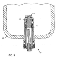
FIGURE 3 is a fragmented cross-sectional view of the contaminant detector ofFIG. 2 mounted in the bottom of a fuel tank; -
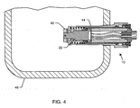
FIGURE 4 is a fragmented cross-sectional view similar toFIG. 3 , illustrating the contaminant detector mounted in a sidewall of the fuel tank; and -
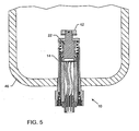
FIGURE 5 is a fragmented cross-sectional view similar toFIG. 3 , showing the contaminant detector mounted in the bottom wall of a fuel tank while in a testing mode. - The present invention is directed to a
contaminant detector 10 for detecting the presence of a contaminating fluid in a base fluid. The following detailed description will describe thedetector 10 in terms of a fueling system water detection device that detects the presence of water accumulated in the bottom of a fuel tank. However, the principles of the invention are applicable to systems for the detection of contaminants other than water in the presence of base fluids other than fuel. - As shown in
FIGS. 1 and 2 , thecontaminant detector 10 consists primarily of aconductive core 12 in aconductive housing 14. Thedetector 10 includes a slidingseal 16 adjacent a proximate end of thedetector 10 and thehousing 14 includes one ormore openings 18 adjacent the distal end of thedetector 10. - The
conductive core 12 has asensor probe 22 that extends from the core 12 in non-conductive relation, and acircuit board 24 electrically coupled to thesensor probe 22. Thecore 12 is configured such that it fits snugly inside thehousing 14 of thedetector 10. Thesensor probe 22 is positioned at the distal end of the core 12 such that at least a portion of thesensor probe 22 is external to thecore 12. Aninsulator seal cartridge 28 is positioned around the junction between the core 12 and thesensor probe 22.Seals core 12. - The
circuit board 24 is positioned inside thecore 12 and electrically connected to thesensor probe 22. Thecircuit board 24 is also electrically connected to aconnector assembly 26 bywires 34 or other means commonly known in the art. Theconnector assembly 26 is positioned at the proximate end of thecore 12 and retained in place byfasteners 36. Aninsulator 38 is positioned inside the core 12 to electrically insulate thesensor probe 22 andcircuit board 24 from thecore 12. Theinsulator seal cartridge 28 also assists in this electrical insulation. Theinsulator 38 andinsulator seal cartridge 28 are made from dielectric material. - The
core 12 andhousing 14 are both conductive. However, the present invention does not require electrical current to pass through thecore 12, thehousing 14 or the base fluid. Thecore 12 and thehousing 14 possess a relatively low capacitance with each other, which assists in generating a closed field loop as described below - A
spring 40 is positioned inside thehousing 14 between the distal end of the housing and the distal end of thecore 12. At least a portion of thesensor probe 22 extends beyond the distal end of thehousing 14. Asensor cap 42 is affixed to that portion of thesensor probe 22 that extends beyond the distal end of thehousing 14. Aninsulator washer 44 is positioned between thesensor cap 42 and thehousing 14 to maintain the electrical insulation of the sensor probe from thehousing 14 andcore 12. Thespring 40 in combination with thesensor cap 42 biases the sensor probe 22 a fixed distance away from thehousing 14. As will be described below this fixed distance biasing is necessary for the operation of thecontaminant detector 10. - As shown in
FIGS. 3 and4 , thecontaminant detector 10 may be mounted in the bottom wall or sidewall of afuel tank 46. When thedetection device assembly 10 is mounted in afuel tank 46 theopenings 18 in the distal end of thehousing 14 allow liquid fuel or liquid water to reach thesensor probe 22. Theseals insulator seal cartridge 28 prevent fuel or water from entering the inside of thecore 12 and interfering with the electronic parts therein. The slidingseal 16 in the housing prevents any external leakage between thehousing 14 and thecore 12. - In operation, electrical power is supplied to the
circuit board 24 through theconnector assembly 26. Theelectronic circuit board 24 creates an electrical charge to thesensor probe 22 and an opposite electrical charge to thecore 12 andhousing 14. Thesensor probe 22 on the one hand and thecore 12 andhousing 14 on the other hand serve the function of sensing electrodes. These sensing electrodes with opposite charges actively project a "closed field loop" through the liquid fuel in their proximity. Using the "closed field loop", thecircuit board 24 measures the capacitance through the liquid in the proximity of the sensing electrodes. In the presence of pure fuel, the capacitance measured by thecircuit board 24 is a known value. When water accumulates in the fuel tank and the water level reaches a close proximity to both thesensor probe 22 and the core 12/housing 14, thecircuit board 24 measures changes in the localized capacitance. When the capacitance changes by a predetermined magnitude, indicating the presence of too much water, thecircuit board 24 produces an output alarm signal through theconnector assembly 26 to an external alarm system (not shown). - It is not necessary that the contaminant water actually contact the
sensor probe 22 orcore 12 /housing 14. Because the capacitance is measured using the closed field loop, the alarm output signal can be generated as the water level merely approaches thesensor probe 22 orcore 12/housing 14. It is this feature that allows thecircuit board 24 to detect the presence of water even if the sensing electrodes are covered with a film of bacterial micro growth, contaminants, corrosion, etc. The water detection function of the present invention is performed solely through electronic means without any mechanical moving parts. - In a testing mode of the present invention, the
contaminant detector 10 is designed to incorporate a test feature which simulates the presence of water in proximity to the sensing electrodes without the actual introduction of water. As described in the operation mode, thecircuit board 24 measures any variation of the localized capacitance in order to determine the presence of water in proximity to the sensing electrodes. The variation of localized capacitance can be simulated by varying the distance between thesensor probe 22 and thehousing 14. As illustrated inFIG. 5 , the core 12 can be pushed toward thehousing 14 against the biasing of thespring 40. As thesensor probe 22 approaches thehousing 14 to within a predetermined distance, the localized capacitance between thesensor probe 22 andhousing 14 approach the capacitance measured in the operation mode of thedetector 10 in the presence of water. In this testing mode, an output signal will be sent to the external alarm system by thecircuit board 24, simulating the detection of excessive accumulated water in thefuel tank 46. Therefore, testing of the detection device assembly can be achieved without the introduction of water into thefuel tank 46. - The function of the
housing 14 in the present invention is to facilitate testing of thecontaminant detector 10 without the introduction of water into thefuel tank 46. In situations where the testing requirements are not applicable, the core 12 can be used independently as thecontaminant detector 10 without the inclusion of thehousing 14. In this case, thesensor core 12 may be mounted directly into thefuel tank 46. - As mentioned above, the
contaminant detector 10 of the present invention may be applied to the detection of the presence of any undesirable fluid in another. For the technology to be applicable, the subject fluids must possess the following physical and electrical properties: - o The fluids must not be soluble in one another;
- o The fluids must be of different densities such that they will separate from one another in gravity; and
- o The fluids must have different dielectric properties.
- The placement of the
contaminant detector 10 in thetank 46 may have to be changed depending upon the relative densities of the subject fluids. If the base fluid is more dense than the contaminant fluid then the contaminant fluid will float on top of the base fluid. In this case thecontaminant detector 10 will need to be positioned such that it is near the area of thetank 46 in which the contaminant fluid will settle. - Although various embodiment of the present invention have been described in detail for purposes of illustration, various modifications may be made without departing from the scope of the invention.
Claims (16)
- A process for detecting the presence of a contaminating fluid in a base fluid, comprising the steps of:positioning a contaminant detector (10) having a conductive core (12) in a tank (46) containing the base fluid, the contaminant detector further comprising a sensor probe (22) extending from the core in non-conductive relation, and a circuit board (24) electrically coupled to the sensor probe;applying electrical power to the circuit board (24);creating an electrical charge in the sensor probe (22) and an opposite electrical charge in the core (12) to create a closed field loop through the base fluid;measuring the capacitance of the base fluid in proximity to the sensor probe (22) and the core (12); andproducing an alarm signal in response to a change in the measured capacitance to indicate the presence of the contaminating fluid in the base fluid above a pre-set threshold;wherein the contaminant detector includes a conductive housing (14) in which the core (12) is slidingly disposed in conductive relation;the process further comprising a testing mode comprising the steps of:biasing the sensor probe (22) a set distance away from the housing (14);pushing the sensor probe (22) to within a pre-determined distance of the housing (14) against the bias; andproducing an alarm signal in response to the measured capacitance.
- The process of claim 1, wherein the creating step includes the step of creating the opposite electrical charge in the housing (14).
- The process of claim 2, wherein the measuring step includes the step of measuring the capacitance of the base fluid in proximity to the sensor probe (22) and the housing (14).
- The process of any one of the preceding claims, wherein the pushing step changes the capacitance between the sensor probe (22) and the housing (14) such that it approaches the capacitance which would be measured when the sensor probe is biased a set distance away from the housing and an amount of the contaminating fluid in the base fluid is above the pre-set threshold.
- The process of any one of the preceding claims, wherein the base fluid comprises a fuel and the contaminating fluid comprises water.
- The process of any one of the preceding claims, wherein the contaminant detector is mounted vertically in a bottom wall of the tank (46).
- The process of any one of claims 1 to 5, wherein the contaminant detector is mounted horizontally in a side wall of the tank (46).
- The process of any one of the preceding claims, wherein the circuit board (24) is disposed within the core (12).
- The process of any one of the preceding claims, wherein the electrical power is provided from a source external to the tank (46).
- A contaminant detector disposed within a base fluid for detecting the presence of a contaminating fluid, comprising:a conductive housing (14);a conductive core (12) slidingly disposed within the housing (14) in conductive relation;a conductive sensor probe (22) extending from the core in non-conductive relation;means for charging the sensor probe (22) and providing an opposite electrical charge to the core (12) and housing (14) to create a closed field loop through the base fluid;means for measuring the capacitance of the base fluid in proximity to the sensor probe (22) and the housing (14); andmeans for producing an alarm signal in response to a change in the measured capacitance to indicate the presence of the contaminating fluid in the base fluid above a pre-set threshold;the contaminant detector further comprising a sliding seal (16) between the core (12) and the housing (14) adjacent the proximate end of the core.
- The contaminant detector of claim 10, wherein the housing (14) extends from the proximate end of the core (12) to beyond the distal end of the core, the housing configured such that the sensor probe (22) extends beyond the distal end of the housing in non-conductive relation.
- The contaminant detector of any one of claims 10 to 11, further comprising a sensor cap (42) mounted over that portion of the sensor probe (22) that extends beyond the housing (14) and a spring (40) biasing the sensor probe away from the housing.
- The contaminant detector of claim 12, further comprising an insulating washer (44) between the sensor cap (42) and the housing (14).
- The contaminant detector of any one of claims 10 to 13, further comprising at least two openings (18) in the housing (14), adjacent the sensor probe (22).
- The contaminant detector of any one of claims 10 to 14, further comprising an insulator (38) between the core (12) and the sensor probe (22).
- The contaminant detector of any one of claims 10 to 14, further comprising an insulator seal cartridge (28) between the core (12) and the sensor probe (22).
Applications Claiming Priority (2)
| Application Number | Priority Date | Filing Date | Title |
|---|---|---|---|
| US11/625,689 US7574899B2 (en) | 2007-01-22 | 2007-01-22 | Fluid contaminant detection device |
| PCT/US2007/081532 WO2008091418A1 (en) | 2007-01-22 | 2007-10-16 | Fluid contaminant detection device |
Publications (3)
| Publication Number | Publication Date |
|---|---|
| EP2106552A1 EP2106552A1 (en) | 2009-10-07 |
| EP2106552A4 EP2106552A4 (en) | 2013-02-13 |
| EP2106552B1 true EP2106552B1 (en) | 2014-02-26 |
Family
ID=39640689
Family Applications (1)
| Application Number | Title | Priority Date | Filing Date |
|---|---|---|---|
| EP07854103.4A Active EP2106552B1 (en) | 2007-01-22 | 2007-10-16 | Fluid contaminant detection device |
Country Status (6)
| Country | Link |
|---|---|
| US (1) | US7574899B2 (en) |
| EP (1) | EP2106552B1 (en) |
| CN (1) | CN101636660B (en) |
| BR (1) | BRPI0720334A2 (en) |
| SA (1) | SA08280768B1 (en) |
| WO (1) | WO2008091418A1 (en) |
Families Citing this family (7)
| Publication number | Priority date | Publication date | Assignee | Title |
|---|---|---|---|---|
| US8410948B2 (en) * | 2008-05-12 | 2013-04-02 | John Vander Horst | Recreational vehicle holding tank sensor probe |
| GB0822415D0 (en) * | 2008-12-09 | 2009-01-14 | Denby Carl | Storage tank monitoring apparatus |
| WO2012122523A1 (en) * | 2011-03-09 | 2012-09-13 | Warren Oden Lee | Three dimensional transducer |
| US9522353B2 (en) | 2013-08-13 | 2016-12-20 | Michael Richardson | Fuel filter device |
| CN105203602B (en) * | 2015-10-15 | 2018-05-01 | 广东美的厨房电器制造有限公司 | Kitchen ventilator and its soil level detection device and method |
| US11426648B2 (en) | 2018-02-14 | 2022-08-30 | Brunswick Bowling Products Llc | Contaminant detection/sensing system for bowling lane conditioning machine |
| US11658443B2 (en) * | 2021-04-13 | 2023-05-23 | Apple Inc. | Liquid detection and corrosion mitigation |
Family Cites Families (13)
| Publication number | Priority date | Publication date | Assignee | Title |
|---|---|---|---|---|
| US1960168A (en) * | 1933-03-28 | 1934-05-22 | Light Sensitive Apparatus Corp | Oil tester using radio frequency |
| US4296310A (en) * | 1979-08-20 | 1981-10-20 | Alco Standard Corporation | Cooking device with water detecting means |
| US4316174A (en) * | 1979-12-26 | 1982-02-16 | General Motors Corporation | Threshold detector for a condition indication |
| US4349882A (en) * | 1980-08-22 | 1982-09-14 | Veeder Industries Inc. | Liquid level measuring system |
| US5033289A (en) * | 1988-05-16 | 1991-07-23 | Texaco Inc. | Water cut monitoring means and method |
| CN2058852U (en) * | 1989-09-25 | 1990-07-04 | 廉其杭 | Mornitor alarming device for liquid level of medical drainage-bottle |
| US5260667A (en) * | 1991-12-02 | 1993-11-09 | Intevep, S.A. | Method and apparatus for determining the percentage water condent of oil in water emulsion by specific admittance measurement |
| US5547565A (en) * | 1994-12-05 | 1996-08-20 | Baldwin Filters, Inc. | Fuel/water separator with adaptor plate for drain valve and water detector |
| US5824889A (en) * | 1997-03-06 | 1998-10-20 | Kavlico Corporation | Capacitive oil deterioration and contamination sensor |
| CN2311773Y (en) * | 1997-09-04 | 1999-03-24 | 王喜民 | Boiler water quality monitoring instrument |
| JP2001041918A (en) * | 1999-08-03 | 2001-02-16 | Honda Motor Co Ltd | Oil gas concentration detector |
| US6690281B2 (en) * | 2000-12-18 | 2004-02-10 | Joseph A. Palmer | Water detector and alarm |
| US6885199B2 (en) * | 2001-05-17 | 2005-04-26 | Siemens Vdo Automotive Corp. | Fuel sensor |
-
2007
- 2007-01-22 US US11/625,689 patent/US7574899B2/en active Active
- 2007-10-16 BR BRPI0720334-9A2A patent/BRPI0720334A2/en not_active IP Right Cessation
- 2007-10-16 EP EP07854103.4A patent/EP2106552B1/en active Active
- 2007-10-16 WO PCT/US2007/081532 patent/WO2008091418A1/en not_active Ceased
- 2007-10-16 CN CN200780050274XA patent/CN101636660B/en not_active Expired - Fee Related
-
2008
- 2008-01-07 SA SA8280768A patent/SA08280768B1/en unknown
Also Published As
| Publication number | Publication date |
|---|---|
| CN101636660A (en) | 2010-01-27 |
| CN101636660B (en) | 2013-11-13 |
| SA08280768B1 (en) | 2011-09-13 |
| BRPI0720334A2 (en) | 2015-01-27 |
| EP2106552A4 (en) | 2013-02-13 |
| US20080174442A1 (en) | 2008-07-24 |
| US7574899B2 (en) | 2009-08-18 |
| WO2008091418A1 (en) | 2008-07-31 |
| EP2106552A1 (en) | 2009-10-07 |
Similar Documents
| Publication | Publication Date | Title |
|---|---|---|
| EP2106552B1 (en) | Fluid contaminant detection device | |
| RU2761093C9 (en) | Capacitive interface level sensor with coupling for electrode body | |
| RU2789846C2 (en) | Fuel storage tank containing one capacitive sensor of medium interface level | |
| RU2784786C2 (en) | Fuel tank of a vehicle containing one capacitive interface level sensor | |
| RU2790197C2 (en) | Connecting coupling for case for electrodes of capacitive interface level sensor | |
| RU2790412C2 (en) | Fuel storage tank containing several capacitive sensors of medium interface level | |
| RU2784642C2 (en) | Fuel tank of a vehicle containing one capacitive interface level sensor | |
| RU2784638C2 (en) | Fuel tank of a vehicle containing several capacitive interface level sensors | |
| RU2784703C2 (en) | Fuel tank of a vehicle containing several capacitive interface level sensors | |
| RU2790408C2 (en) | Fuel storage tank containing one capacitive sensor of medium interface level | |
| RU2784596C2 (en) | Sensitive element of capacitive level sensor of interface( | |
| RU2790473C2 (en) | Fuel storage tank containing several capacitive sensors of medium interface level | |
| RU2784785C2 (en) | Fuel tank of a vehicle containing several capacitive interface level sensors | |
| RU2784614C2 (en) | Liquid flow monitoring system containing one capacitive interface level sensor | |
| RU2784644C2 (en) | Fuel tank of a vehicle containing several capacitive interface level sensors | |
| RU2784643C2 (en) | Vehicle fuel tank | |
| RU2784608C2 (en) | Capacitive interface level sensor | |
| RU2790411C2 (en) | Fuel storage tank containing several capacitive sensors of medium interface level | |
| RU2784646C2 (en) | Fuel tank of a vehicle containing one capacitive interface level sensor | |
| RU2784748C2 (en) | Fuel tank of a vehicle containing one capacitive interface level sensor | |
| RU2790424C2 (en) | Method for preliminary calibration of capacitive level sensor of interface | |
| RU2782968C2 (en) | Fuel tank of vehicle | |
| RU2789720C2 (en) | Fuel canister for fuel transport, containing one capacitive interface level sensor | |
| RU2789715C2 (en) | Fuel storage tank containing several capacitive interface level sensors | |
| RU2790426C2 (en) | Case for electrodes of capacitive interface sensor |
Legal Events
| Date | Code | Title | Description |
|---|---|---|---|
| PUAI | Public reference made under article 153(3) epc to a published international application that has entered the european phase |
Free format text: ORIGINAL CODE: 0009012 |
|
| 17P | Request for examination filed |
Effective date: 20090722 |
|
| AK | Designated contracting states |
Kind code of ref document: A1 Designated state(s): AT BE BG CH CY CZ DE DK EE ES FI FR GB GR HU IE IS IT LI LT LU LV MC MT NL PL PT RO SE SI SK TR |
|
| RIN1 | Information on inventor provided before grant (corrected) |
Inventor name: WONG, TAK-YIU Inventor name: DALTON, TIMOTHY ALLEN Inventor name: MINOTT, BRUCE ROSS |
|
| DAX | Request for extension of the european patent (deleted) | ||
| A4 | Supplementary search report drawn up and despatched |
Effective date: 20130116 |
|
| RIC1 | Information provided on ipc code assigned before grant |
Ipc: G01R 27/08 20060101AFI20130110BHEP |
|
| GRAP | Despatch of communication of intention to grant a patent |
Free format text: ORIGINAL CODE: EPIDOSNIGR1 |
|
| INTG | Intention to grant announced |
Effective date: 20131001 |
|
| GRAS | Grant fee paid |
Free format text: ORIGINAL CODE: EPIDOSNIGR3 |
|
| GRAA | (expected) grant |
Free format text: ORIGINAL CODE: 0009210 |
|
| AK | Designated contracting states |
Kind code of ref document: B1 Designated state(s): AT BE BG CH CY CZ DE DK EE ES FI FR GB GR HU IE IS IT LI LT LU LV MC MT NL PL PT RO SE SI SK TR |
|
| REG | Reference to a national code |
Ref country code: GB Ref legal event code: FG4D |
|
| REG | Reference to a national code |
Ref country code: CH Ref legal event code: EP |
|
| REG | Reference to a national code |
Ref country code: AT Ref legal event code: REF Ref document number: 653892 Country of ref document: AT Kind code of ref document: T Effective date: 20140315 |
|
| REG | Reference to a national code |
Ref country code: IE Ref legal event code: FG4D |
|
| REG | Reference to a national code |
Ref country code: DE Ref legal event code: R096 Ref document number: 602007035280 Country of ref document: DE Effective date: 20140410 |
|
| REG | Reference to a national code |
Ref country code: NL Ref legal event code: VDEP Effective date: 20140226 |
|
| REG | Reference to a national code |
Ref country code: AT Ref legal event code: MK05 Ref document number: 653892 Country of ref document: AT Kind code of ref document: T Effective date: 20140226 |
|
| REG | Reference to a national code |
Ref country code: LT Ref legal event code: MG4D |
|
| PG25 | Lapsed in a contracting state [announced via postgrant information from national office to epo] |
Ref country code: LT Free format text: LAPSE BECAUSE OF FAILURE TO SUBMIT A TRANSLATION OF THE DESCRIPTION OR TO PAY THE FEE WITHIN THE PRESCRIBED TIME-LIMIT Effective date: 20140226 Ref country code: IS Free format text: LAPSE BECAUSE OF FAILURE TO SUBMIT A TRANSLATION OF THE DESCRIPTION OR TO PAY THE FEE WITHIN THE PRESCRIBED TIME-LIMIT Effective date: 20140626 |
|
| PG25 | Lapsed in a contracting state [announced via postgrant information from national office to epo] |
Ref country code: CY Free format text: LAPSE BECAUSE OF FAILURE TO SUBMIT A TRANSLATION OF THE DESCRIPTION OR TO PAY THE FEE WITHIN THE PRESCRIBED TIME-LIMIT Effective date: 20140226 Ref country code: FI Free format text: LAPSE BECAUSE OF FAILURE TO SUBMIT A TRANSLATION OF THE DESCRIPTION OR TO PAY THE FEE WITHIN THE PRESCRIBED TIME-LIMIT Effective date: 20140226 Ref country code: SE Free format text: LAPSE BECAUSE OF FAILURE TO SUBMIT A TRANSLATION OF THE DESCRIPTION OR TO PAY THE FEE WITHIN THE PRESCRIBED TIME-LIMIT Effective date: 20140226 Ref country code: AT Free format text: LAPSE BECAUSE OF FAILURE TO SUBMIT A TRANSLATION OF THE DESCRIPTION OR TO PAY THE FEE WITHIN THE PRESCRIBED TIME-LIMIT Effective date: 20140226 Ref country code: PT Free format text: LAPSE BECAUSE OF FAILURE TO SUBMIT A TRANSLATION OF THE DESCRIPTION OR TO PAY THE FEE WITHIN THE PRESCRIBED TIME-LIMIT Effective date: 20140626 Ref country code: NL Free format text: LAPSE BECAUSE OF FAILURE TO SUBMIT A TRANSLATION OF THE DESCRIPTION OR TO PAY THE FEE WITHIN THE PRESCRIBED TIME-LIMIT Effective date: 20140226 |
|
| PG25 | Lapsed in a contracting state [announced via postgrant information from national office to epo] |
Ref country code: BE Free format text: LAPSE BECAUSE OF FAILURE TO SUBMIT A TRANSLATION OF THE DESCRIPTION OR TO PAY THE FEE WITHIN THE PRESCRIBED TIME-LIMIT Effective date: 20140226 Ref country code: LV Free format text: LAPSE BECAUSE OF FAILURE TO SUBMIT A TRANSLATION OF THE DESCRIPTION OR TO PAY THE FEE WITHIN THE PRESCRIBED TIME-LIMIT Effective date: 20140226 |
|
| PG25 | Lapsed in a contracting state [announced via postgrant information from national office to epo] |
Ref country code: CZ Free format text: LAPSE BECAUSE OF FAILURE TO SUBMIT A TRANSLATION OF THE DESCRIPTION OR TO PAY THE FEE WITHIN THE PRESCRIBED TIME-LIMIT Effective date: 20140226 Ref country code: DK Free format text: LAPSE BECAUSE OF FAILURE TO SUBMIT A TRANSLATION OF THE DESCRIPTION OR TO PAY THE FEE WITHIN THE PRESCRIBED TIME-LIMIT Effective date: 20140226 Ref country code: EE Free format text: LAPSE BECAUSE OF FAILURE TO SUBMIT A TRANSLATION OF THE DESCRIPTION OR TO PAY THE FEE WITHIN THE PRESCRIBED TIME-LIMIT Effective date: 20140226 Ref country code: RO Free format text: LAPSE BECAUSE OF FAILURE TO SUBMIT A TRANSLATION OF THE DESCRIPTION OR TO PAY THE FEE WITHIN THE PRESCRIBED TIME-LIMIT Effective date: 20140226 |
|
| REG | Reference to a national code |
Ref country code: DE Ref legal event code: R097 Ref document number: 602007035280 Country of ref document: DE |
|
| PG25 | Lapsed in a contracting state [announced via postgrant information from national office to epo] |
Ref country code: ES Free format text: LAPSE BECAUSE OF FAILURE TO SUBMIT A TRANSLATION OF THE DESCRIPTION OR TO PAY THE FEE WITHIN THE PRESCRIBED TIME-LIMIT Effective date: 20140226 Ref country code: SK Free format text: LAPSE BECAUSE OF FAILURE TO SUBMIT A TRANSLATION OF THE DESCRIPTION OR TO PAY THE FEE WITHIN THE PRESCRIBED TIME-LIMIT Effective date: 20140226 Ref country code: PL Free format text: LAPSE BECAUSE OF FAILURE TO SUBMIT A TRANSLATION OF THE DESCRIPTION OR TO PAY THE FEE WITHIN THE PRESCRIBED TIME-LIMIT Effective date: 20140226 |
|
| PLBE | No opposition filed within time limit |
Free format text: ORIGINAL CODE: 0009261 |
|
| STAA | Information on the status of an ep patent application or granted ep patent |
Free format text: STATUS: NO OPPOSITION FILED WITHIN TIME LIMIT |
|
| 26N | No opposition filed |
Effective date: 20141127 |
|
| REG | Reference to a national code |
Ref country code: DE Ref legal event code: R097 Ref document number: 602007035280 Country of ref document: DE Effective date: 20141127 |
|
| PG25 | Lapsed in a contracting state [announced via postgrant information from national office to epo] |
Ref country code: IT Free format text: LAPSE BECAUSE OF FAILURE TO SUBMIT A TRANSLATION OF THE DESCRIPTION OR TO PAY THE FEE WITHIN THE PRESCRIBED TIME-LIMIT Effective date: 20140226 |
|
| PG25 | Lapsed in a contracting state [announced via postgrant information from national office to epo] |
Ref country code: SI Free format text: LAPSE BECAUSE OF FAILURE TO SUBMIT A TRANSLATION OF THE DESCRIPTION OR TO PAY THE FEE WITHIN THE PRESCRIBED TIME-LIMIT Effective date: 20140226 Ref country code: MC Free format text: LAPSE BECAUSE OF FAILURE TO SUBMIT A TRANSLATION OF THE DESCRIPTION OR TO PAY THE FEE WITHIN THE PRESCRIBED TIME-LIMIT Effective date: 20140226 Ref country code: LU Free format text: LAPSE BECAUSE OF FAILURE TO SUBMIT A TRANSLATION OF THE DESCRIPTION OR TO PAY THE FEE WITHIN THE PRESCRIBED TIME-LIMIT Effective date: 20141016 |
|
| REG | Reference to a national code |
Ref country code: CH Ref legal event code: PL |
|
| REG | Reference to a national code |
Ref country code: IE Ref legal event code: MM4A |
|
| PG25 | Lapsed in a contracting state [announced via postgrant information from national office to epo] |
Ref country code: CH Free format text: LAPSE BECAUSE OF NON-PAYMENT OF DUE FEES Effective date: 20141031 Ref country code: LI Free format text: LAPSE BECAUSE OF NON-PAYMENT OF DUE FEES Effective date: 20141031 |
|
| PG25 | Lapsed in a contracting state [announced via postgrant information from national office to epo] |
Ref country code: IE Free format text: LAPSE BECAUSE OF NON-PAYMENT OF DUE FEES Effective date: 20141016 |
|
| PG25 | Lapsed in a contracting state [announced via postgrant information from national office to epo] |
Ref country code: BG Free format text: LAPSE BECAUSE OF FAILURE TO SUBMIT A TRANSLATION OF THE DESCRIPTION OR TO PAY THE FEE WITHIN THE PRESCRIBED TIME-LIMIT Effective date: 20140226 |
|
| PG25 | Lapsed in a contracting state [announced via postgrant information from national office to epo] |
Ref country code: GR Free format text: LAPSE BECAUSE OF FAILURE TO SUBMIT A TRANSLATION OF THE DESCRIPTION OR TO PAY THE FEE WITHIN THE PRESCRIBED TIME-LIMIT Effective date: 20140527 |
|
| PG25 | Lapsed in a contracting state [announced via postgrant information from national office to epo] |
Ref country code: MT Free format text: LAPSE BECAUSE OF FAILURE TO SUBMIT A TRANSLATION OF THE DESCRIPTION OR TO PAY THE FEE WITHIN THE PRESCRIBED TIME-LIMIT Effective date: 20140226 Ref country code: HU Free format text: LAPSE BECAUSE OF FAILURE TO SUBMIT A TRANSLATION OF THE DESCRIPTION OR TO PAY THE FEE WITHIN THE PRESCRIBED TIME-LIMIT; INVALID AB INITIO Effective date: 20071016 Ref country code: TR Free format text: LAPSE BECAUSE OF FAILURE TO SUBMIT A TRANSLATION OF THE DESCRIPTION OR TO PAY THE FEE WITHIN THE PRESCRIBED TIME-LIMIT Effective date: 20140226 |
|
| REG | Reference to a national code |
Ref country code: FR Ref legal event code: PLFP Year of fee payment: 10 |
|
| REG | Reference to a national code |
Ref country code: FR Ref legal event code: PLFP Year of fee payment: 11 |
|
| REG | Reference to a national code |
Ref country code: FR Ref legal event code: PLFP Year of fee payment: 12 |
|
| REG | Reference to a national code |
Ref country code: DE Ref legal event code: R082 Ref document number: 602007035280 Country of ref document: DE Ref country code: DE Ref legal event code: R081 Ref document number: 602007035280 Country of ref document: DE Owner name: EATON INTELLIGENT POWER LIMITED, IE Free format text: FORMER OWNER: ARGO-TECH CORP. COSTA MESA, COSTA MESA, CALIF., US |
|
| P01 | Opt-out of the competence of the unified patent court (upc) registered |
Effective date: 20230521 |
|
| PGFP | Annual fee paid to national office [announced via postgrant information from national office to epo] |
Ref country code: GB Payment date: 20250923 Year of fee payment: 19 |
|
| PGFP | Annual fee paid to national office [announced via postgrant information from national office to epo] |
Ref country code: FR Payment date: 20250924 Year of fee payment: 19 |
|
| PGFP | Annual fee paid to national office [announced via postgrant information from national office to epo] |
Ref country code: DE Payment date: 20250923 Year of fee payment: 19 |