EP2106544B1 - Sensor element with offset current by way of h2o decomposition - Google Patents
Sensor element with offset current by way of h2o decomposition Download PDFInfo
- Publication number
- EP2106544B1 EP2106544B1 EP07848019.1A EP07848019A EP2106544B1 EP 2106544 B1 EP2106544 B1 EP 2106544B1 EP 07848019 A EP07848019 A EP 07848019A EP 2106544 B1 EP2106544 B1 EP 2106544B1
- Authority
- EP
- European Patent Office
- Prior art keywords
- air
- fuel ratio
- pumping
- pumping current
- lean
- Prior art date
- Legal status (The legal status is an assumption and is not a legal conclusion. Google has not performed a legal analysis and makes no representation as to the accuracy of the status listed.)
- Not-in-force
Links
Images

Classifications
-
- G—PHYSICS
- G01—MEASURING; TESTING
- G01N—INVESTIGATING OR ANALYSING MATERIALS BY DETERMINING THEIR CHEMICAL OR PHYSICAL PROPERTIES
- G01N27/00—Investigating or analysing materials by the use of electric, electrochemical, or magnetic means
- G01N27/26—Investigating or analysing materials by the use of electric, electrochemical, or magnetic means by investigating electrochemical variables; by using electrolysis or electrophoresis
- G01N27/403—Cells and electrode assemblies
- G01N27/406—Cells and probes with solid electrolytes
- G01N27/407—Cells and probes with solid electrolytes for investigating or analysing gases
- G01N27/4071—Cells and probes with solid electrolytes for investigating or analysing gases using sensor elements of laminated structure
Definitions
- the invention is based on known sensor elements which are based on electrolytic properties of certain solids, ie the ability of these solids to conduct certain ions.
- sensor elements are used in particular in motor vehicles to measure air-fuel-gas mixture compositions.
- sensor elements of this type are used in so-called “lambda sensors” and play an essential role in the reduction of pollutants in exhaust gases, both in gasoline engines and in diesel technology.
- One embodiment represents the so-called "jump probe” whose measuring principle is based on the measurement of an electrochemical potential difference between a reference electrode exposed to a reference gas and a measuring electrode exposed to the gas mixture to be measured.
- the reference electrode and the measuring electrode are connected to one another via the solid electrolyte, with zirconium dioxide (eg yttrium-stabilized zirconium dioxide) or similar ceramics being used as the solid electrolyte due to its oxygen-ion-conducting properties.
- zirconium dioxide eg yttrium-stabilized zirconium dioxide
- similar ceramics being used as the solid electrolyte due to its oxygen-ion-conducting properties.
- the potential difference between the electrodes especially at the transition between rich gas mixture and lean gas mixture on a characteristic jump, which can be used to measure the gas mixture composition and / or to regulate.
- Various embodiments of such jump probes which are also referred to as "Nernst cells” are, for example, in DE 10 2004
- pump cells in which an electrical “pumping voltage” is applied to two electrodes connected via the solid electrolyte, the "pump current” being measured by the pump cell.
- both electrodes are usually connected to the gas mixture to be measured.
- One of the two electrodes (usually via a permeable protective layer) is exposed directly to the gas mixture to be measured.
- this electrode may also be exposed to an air reference.
- the second of the two electrodes is usually designed such that the gas mixture can not reach this electrode directly, but must first penetrate a so-called "diffusion barrier" in order to reach a cavity adjacent to this second electrode.
- the diffusion barrier used is usually a porous ceramic structure with specifically adjustable pore radii. If lean exhaust gas passes through this diffusion barrier into the cavity, oxygen molecules are electrochemically reduced to oxygen ions by means of the pumping voltage at the second, negative electrode, are transported through the solid electrolyte to the first, positive electrode and released there again as free oxygen.
- the sensor elements are usually operated in the so-called limiting current operation, that is, in an operation in which the pump voltage is selected such that the oxygen entering through the diffusion barrier is completely pumped to the counter electrode. In this operation, the pumping current is approximately proportional to the partial pressure of the oxygen in the exhaust gas mixture, so that such sensor elements are often referred to as proportional sensors.
- the sensor elements may contain one or more cells operating according to the jump sensor principle and one or more pump cells.
- An example of a "double cell" is in EP 0 678 740 B1 described.
- Various modifications of this multicellular construction are known.
- a method for measuring an air ratio ⁇ of a gas mixture in at least one gas space, which largely avoids the disadvantages of the processes known from the prior art.
- Existing sensor elements can continue to be used, since the method essentially proposes a suitable wiring, which also allows a measurement of air ratios in the rich air range.
- At least one sensor element which has at least two electrodes and at least one solid electrolyte connecting these at least two electrodes.
- the at least one first electrode with gas mixture from the at least one gas space can be acted upon, for example via a diffusion resistor for limiting the limiting current of the at least one first electrode.
- the at least one second electrode is not connected to the at least one gas space but (for example via an exhaust air or reference channel) to a reference gas space separated from the at least one gas space.
- this may be an engine compartment of the internal combustion engine or else a separate reference gas chamber with an at least approximately known and constant gas mixture composition.
- this second electrode is "fuel gas blind", and the fuel gas reactions described above can not proceed in the region of this at least one second electrode or only to a greatly reduced extent.
- the measuring range of the sensor element in a range ⁇ ⁇ 1.
- the pump current characteristic is shifted into the range of rich air numbers or into this range, so that this pump current characteristic of the comparatively simple, single-cell sensor element also has ⁇ ⁇ 1 in this extended measurement range can be used.
- the proposed method can also be used with more complex, for example multi-cell sensor structures.
- this oxygen-containing component may be water which is either already present in the gas mixture and / or which is active by reaction of hydrogen and oxygen at the at least one first electrode (which is usually catalytically, in particular electrocatalytically , for example, by using platinum as electrode material) forms.
- the oxygen-containing component is water
- the increased pumping voltage be chosen above 700 mV, but preferably the increased pumping voltage is not greater than 1.2 V, for example 1.0 V.
- the operating state in which the increased pumping voltage is used is referred to below as the "offset state". In this offset state, the increased pumping current (increased by the additional proportion of oxygen produced by the electrolysis) and from the increased pumping current to the air ratio ⁇ is closed.
- the method according to the invention can be used, for example, in such a way that initially an ordinary lean control state is provided, in which the sensor element is operated in the lean air-fuel range.
- a normal pumping voltage is used, which is below the decomposition voltage of the oxygen-containing component (for example, for water) in the range of 600 to 700 mV.
- the lean pump current is measured and from this the air ratio ⁇ is closed, or this air ratio ⁇ is regulated by appropriate controls (for example, throttle valves, etc.).
- At least one rich state control is provided, in which the above-described at least one offset state is used, that is, in which is operated with increased pump voltages above the decomposition voltage to artificially increase the pumping current and thus the pumping current characteristic in the rich air range to expand.
- this at least one rich control state can be used to set from normal operation with ⁇ > 1 a rich operation and thereby shut down the air ratio controlled.
- FIG. 1 an inventive system 110 for measuring an air ratio ⁇ of a gas mixture in a gas space 112 is shown.
- the system 110 includes a sensor element 114 and an electronic control device 116.
- the electronic control device 116 may be connected to a plurality of sensor elements 114, for example sensor elements 114, which are arranged before and after certain exhaust gas purification devices (for example catalytic converters, filters, etc.). All components are in FIG. 1 only shown schematically.
- the sensor element 114 has a solid electrolyte 118 as well as a first electrode 120 and a second electrode 122.
- first electrode 120 is switched at least temporarily as pump cathode, so that this first electrode is also referred to below as the pump cathode 120 , Accordingly, the second electrode 122 is referred to as a pump anode.
- other circuits are conceivable, for example, circuits with alternating polarities.
- the electrodes 120, 122 are formed in this embodiment as multi-part electrodes, which, however, are electrically connected in each case to individual electrodes 120, 122.
- the pump cathode 120 communicates with a cathode cavity 124, and the pump anode 122 with an anode cavity 126.
- the cathode cavity 124 via a diffusion barrier 128 (for example, a porous material, for example Al 2 O 3 and / or ZrO 2 -based) and a gas inlet hole 130 communicates with the gas space 112
- the anode cavity 126 and the exhaust air duct 132 are filled with a porous element which allows an outflow of oxygen from the anode cavity 126 into the reference gas space 134.
- it is again a porous element based on Al 2 O 3 and / or ZrO 2 .
- the sensor element 114 has a heating element 136, which is arranged in a lower layer plane of the layer structure and which serves to keep the sensor element 114 at a (for example constant operating temperature of, for example, 700 to 800 ° C. (for example 780 ° C.)
- a corresponding control of the heating element 136 may be provided, for example configured with a corresponding temperature control, which in FIG. 1 not shown.
- the temperature control takes place at a constant internal resistance of the sensor element 114.
- the electrodes 120, 122 of the sensor element 114 are connected to the electronic control device 116.
- the electronic control device has a voltage source for applying an external pumping voltage to the pumping electrodes 120, 122.
- a current measuring device 140 is provided to measure a pumping current I p through the sensor element 114.
- the voltage source 138 and the current measuring device are driven and read out by an electronic control unit 142, which is set up to operate the sensor element 114 according to the invention.
- the control electronics 142 for example, have electronic components which provide for adjustment of the pump voltage according to the current operating mode.
- the control electronics 142 may, for example, have memory elements, for example to store measured pump currents and / or characteristic curves and / or further parameters.
- control electronics 142 may include a microcomputer which provides for a corresponding control and readout of the sensor element 114.
- the control electronics 142 may be connected via an interface 144 with other components of the motor vehicle to generate, for example, control signals which set the air ratio ⁇ .
- control and / or control signals can be passed, for example, to an engine control in order to regulate one or more throttle valves in order to adjust the air ratio ⁇ accordingly.
- the electronic control device 116 may receive commands via the interface 144, for example to change from one operating mode to another operating mode, for example from a normal mode to a regeneration mode.
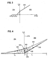
- FIG. 2 is a highly simplified representation of a pumping current characteristic 210 as a function of the air ratio ⁇ for a sensor element 114 according to the structure in FIG. 1 shown.
- This pump current characteristic 210 shows the effect of shielding the pump anode 122 as shown in FIG. 1 the case is.
- the pumping current characteristic 210 in the lean region 212 increases linearly with the air ratio ⁇ , whereas the pumping current characteristic in the rich region 214 is zero.
- FIG. 2 shown course of the pumping current characteristic 210, however, is only observed when the pump voltage used between the electrodes 120 and 122 is selected such that at this voltage no significant decomposition of water at the pumping cathode 120 occurs.
- the sensor element 114 is usually operated in a limiting current mode, so that all of the oxygen arriving at the cathode 120 is pumped through the solid electrolyte 118 to the pumping anode 122.
- the pumping current is thus in saturation and approximately proportional to the oxygen partial pressure.
- the oxygen concentration in the cathode cavity 124 is artificially increased by selecting in an offset state an increased pumping voltage which causes a measurable decomposition of water at the pumping cathode 120.
- FIG. 3 is again shown symbolically and schematically, a pumping current characteristic 310, which is measured at an increased pumping voltage.
- the pumping voltage is raised to above 700 to 800 mV, for example to 1.0 V.
- the pumping current characteristic 310 is in FIG. 3 not shown as a function of the air ratio ⁇ , as in FIG. 2 but in this embodiment as a function of the partial pressures of the individual gases involved.
- the pumping current is plotted as a function of the oxygen partial pressure
- the fuel gas partial pressure eg, hydrogen partial pressure and hydrocarbon partial pressure
- the application is carried out normalized to the oxygen conversion, so that, for example, for hydrogen, since only half an O 2 molecule is required in the formation of water per implemented H 2 molecule, the normalized partial pressure is only half of the real hydrogen partial pressure.
- the different slopes of the pumping current characteristic 310 are due to the different properties of the gases, that is, for example, different diffusion coefficients. Assuming that free oxygen in the rich region 214 on the pump cathode 120 is immediately reacted with fuel gases, the partial pressure of the fuel gases can also be understood as "missing partial pressure" of the oxygen. Due to the different molecular sizes and molecular masses, different partial pumping currents result for the different gas components.
- pump current characteristic 310 with offset shown now also a certain range in the rich air range 214 is available in addition to the lean area 212, within which a measurable pumping current is recorded, and which can be used for example to control the air ratio.
- FIG. 3 symbolically represented characteristic was confirmed experimentally by means of several laboratory measurements.
- the recorded offset of the pumping current characteristic 310 with respect to the pumping current characteristic 210 according to FIG. 2 increased pumping voltage does not depend on the oxygen partial pressure in the region of the pump anode 122, in contrast to the above-described prior art methods of oxygen recirculation or oxygen injection into the cathode cavity 124.
- the pumping voltage can be lowered below the intended value.
- the resulting change in the pumping current ⁇ I p corresponds to or correlates with the offset due to the H 2 O decomposition.
- no further electrode is required in the sensor element 114, so that the comparatively simple structure of the sensor element 114 can be maintained.
- the inventive offset state with decomposition of water can be used by a corresponding electronic control device 116 or an external circuit in almost every sensor element.
- FIGS. 4 to 7 various examples are shown how the offset state according to the invention can be used to effect a measurement and / or control of an air ratio ⁇ .
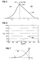
- the pumping current characteristic 210 analogous to FIG. 2 again idealized and linearized, which can still be used in the lean air range 212 (for example in the context of a Magersonde) to measure and regulate an air ratio.
- a lean control state can be provided in which the air ratio is set to a value ⁇ 1 which lies in the lean region 212. This can be, for example, the normal operation of a diesel vehicle.
- FIG. 4 a pumping current characteristic with offset 310 shown in phantom, which in nature of the pumping current characteristic 310 according to FIG. 3 equivalent.
- This pumping current characteristic is, as described above, provided with an offset with respect to the pumping current characteristic 210.
- various methods can be used:
- the pumping current characteristic 310 is known with the offset at an increased pumping voltage (for example at a specific operating state, for example a specific temperature, etc.), then this can be used directly to measure or regulate in the rich region 214.
- the pumping current characteristic 310 with offset can be recorded in a calibration step and stored, for example, in the control electronics 142 (for example in a data memory, an electronic table or the like). In this way it is possible to deduce directly from the measured pumping current with offset the air ratio ⁇ 2 and, for example, to generate a corresponding control signal.
- FIG. 4 A second possibility for setting, measuring and / or regulating air numbers ⁇ 2 ⁇ 1 is shown in FIG. 4 symbolically illustrated by the dotted line 412.
- the air ratio is continuously (or in steps) is lowered, initially controlled along the pumping current characteristic 210 without offset.
- the pump voltage is then suddenly increased in one or more stages, so that due to the above Decomposition effects of pumping current I p to its offset value 414 "jumps".
- this pumping current offset 414 can thus be determined.
- This pump current offset 414 is for example characteristic of the further course of the pump current characteristic 110 with offset in the rich air range 214.
- This calibration characteristic can then be used for example in the further course of the control in the rich air range 214 to measure air numbers and / or to regulate, for example, to a certain air ratio ⁇ 2 ⁇ 1.
- a third variant of the method can be used in which the pump voltage is varied continuously between two values.
- this variation is performed so that the Kirfreqüenz between the pumping voltages is high compared to the speed at which the air ratio changes when driving a certain lambda value.
- other forms of variation can be used, such as jump functions with different dwell times on the different pump voltage values or the like.
- This variation of the pumping voltage between two values which may also be referred to as "wobbling" is associated with a variation of the pumping current which in FIG. 4 symbolically denoted by the dotted line 416.
- the difference .DELTA.I p is measured.
- An example of such a pumping current increase ⁇ I p for a predetermined pump voltage increase ⁇ U p is symbolic in FIG FIG. 5 plotted as a function of the air ratio ⁇ .
- the pumping current overshoot ⁇ I p in the lean air-fuel ratio range 212 decreases approximately linearly with increasing air ratio ⁇ .
- This linear decrease is due to the externally applied pumping voltage ⁇ U p externally not only countering the Nernst voltage U N between the electrodes 120, 122 (which is caused by the partial pressure difference between cathode cavity 124 and anode cavity 126, see below), but also an ohmic voltage drop of the ion current in the solid electrolyte 118, which is approximately proportional to the flowing current and thus (see the characteristic curve 210 in FIG. 4 ) increases approximately proportionally with the air ratio ⁇ .
- the effective pumping voltage U p, eff thus decreases with increasing current and with increasing air ratio ⁇ , so that also the proportion of the decomposition current at the pumping current characteristic decreases approximately linearly.
- the pumping current increase ⁇ I p reaches a maximum in order subsequently to decrease again with smaller ⁇ in the rich region 214.
- This new drop is due to the fact that in this area the Nernst voltage component increases at the effective voltage, whereby the effective pumping voltage U p, eff decreases, which is available for a water decomposition.
- the overshoot characteristic 510 shown can be used for regulation in various ways.
- these superelevation characteristics 510 can for example be completely stored (as calibration characteristics), for example, to enable a targeted start-up of an air ratio ⁇ 2 ⁇ 1, starting from an air ratio ⁇ 1 > 1.
- This pumping current offset 414 may then be in the electronic control device, for example 116 (for example, in the control electronics 142 or a corresponding data memory) are deposited and used to calibrate the characteristic 510.
- one of the characteristic curves 510 can be unambiguously characterized, for example, by the one parameter of the pumping current offset 414, so that it is then possible to unequivocally deduce a specific air ratio ⁇ from a measured pumping current increase ⁇ I p (ie at least in one of the two ranges 214, 212). If now the lean control state is exited and an air ratio ⁇ 2 ⁇ 1 is controlled (ie a region in which the lean-flow characteristic 210 is zero), then by further measuring the pump current overshoot ⁇ I p , based on the stored and calibrated overshoot Characteristic curve 510, the associated lambda value can be determined.
- the pumping current is given in arbitrary units, the pumping voltage U p in volts. If the pumping voltage U p is increased, then the pumping current offset 414 increases.
- the two curves 210 and 310 are removed in FIG FIG. 4 from each other, and the offset described above arises.
- This representation according to FIG. 6 thus, it essentially shows a decomposition characteristic 610 of water as a function of the applied voltage.
- the pump voltage should be selected in normal operation so that the measured pumping current (or the maximum pumping current offset, which occurs due to a, albeit weak, water decomposition in normal operation) is less than 1/10, preferably less than 1/20 of the limiting current of the sensor element 114.
- the pumping voltage can be selected such that pumping current offsets, which are caused by water decomposition, of not more than 20 uA occur.
- the pumping current offsets are in the range between 5 and 20 ⁇ A or below, preferably at approximately 5 ⁇ A. This is usually achieved when pumping voltages of not more than 700 mV are used in normal operation.
- a value for the increased pump voltage which is used in the at least one offset state which is significantly above this 700 mV, that is to say in which a considerable current caused by the water decomposition already flows.
- these may be currents which are of the same order of magnitude as the limiting current of the sensor element 114, that is to say in the range of the above-described value between 500 ⁇ A and 3 mA.
- the pumping current offset 414 is as shown in FIG FIG. 6 can be seen, at a value of 1.0 V compared to a value of 700 mV by a factor of 13 to 14 inflated.
- this overshoot factor depends on the design and H 2 O concentration and is typically between 5 and 15.
- the control electronics 142 can now semiempirisch in the following manner for the rich air range 214 from the measured superelevation characteristic curve 510 (or a certain pumping current increase ⁇ I p ) be deduced on the air ratio ⁇ .
- the following considerations are only approximations.
- the gas composition in the cathode cavity 124 substantially corresponds to the gas mixture composition in the gas space 112 (for example, an exhaust gas).
- the Nernst voltage U N between the electrodes 120, 122 which externally counteracts the externally applied pump voltage U p, increases with decreasing ⁇ according to the jumping probe characteristic (assuming that the above-described resistive component due to a voltage drop in the solid electrolyte 118 in the rich air range 214 is negligible).
- the function f is unique in the range ⁇ ⁇ 1 and thus reversible with an inverse function f -1 .
- the function g can be derived from the Nernst equation.
- FIG. 7 is again the relationship between the Nernst voltage U N and the pumping current I p for ⁇ ⁇ 1 plotted schematically. It can clearly be seen that the drop in the excessive pumping current I p, ⁇ ⁇ 1 for decreasing air ratios ⁇ is essentially due to the above-described increase in the Nernst voltage U N.
Description
Die Erfindung geht aus von bekannten Sensorelementen, welche auf elektrolytischen Eigenschaften bestimmter Festkörper beruhen, also der Fähigkeit dieser Festkörper, bestimmte Ionen zu leiten. Derartige Sensorelemente werden insbesondere in Kraftfahrzeugen eingesetzt, um Luft-Kraftstoff-Gasgemischzusammensetzungen zu messen. Insbesondere werden Sensorelemente dieser Art in so genannten "Lambdasonden" eingesetzt und spielen eine wesentliche Rolle bei der Reduzierung von Schadstoffen in Abgasen, sowohl in Ottomotoren als auch in der Dieseltechnologie.The invention is based on known sensor elements which are based on electrolytic properties of certain solids, ie the ability of these solids to conduct certain ions. Such sensor elements are used in particular in motor vehicles to measure air-fuel-gas mixture compositions. In particular, sensor elements of this type are used in so-called "lambda sensors" and play an essential role in the reduction of pollutants in exhaust gases, both in gasoline engines and in diesel technology.
Mit der so genannten Luftzahl "Lambda" (λ) wird dabei allgemein in der Verbrennungstechnik das Verhältnis zwischen einer tatsächlich angebotenen Luftmasse und einer für die Verbrennung theoretisch benötigten (d. h. stöchiometrischen) Luftmasse bezeichnet. Die Luftzahl wird dabei mittels eines oder mehrerer Sensorelemente zumeist an einer oder mehreren Stellen im Abgastrakt eines Verbrennungsmotors gemessen. Entsprechend weisen "fette" Gasgemische (d. h. Gasgemische mit einem Kraftstoffüberschuss) eine Luftzahl λ < 1 auf, wohingegen "magere" Gasgemische (d. h. Gasgemische mit einem Kraftstoffunterschuss) eine Luftzahl λ > 1 aufweisen. Neben der Kraftfahrzeugtechnik werden derartige und ähnliche Sensorelemente auch in anderen Bereichen der Technik (insbesondere der Verbrennungstechnik) eingesetzt, beispielsweise in der Luftfahrttechnik oder bei der Regelung von Brennern, z. B. in Heizanlagen oder Kraftwerken. Aus dem Stand der Technik sind zahlreiche verschiedene Ausführungsformen der Sensorelemente bekannt und werden beispielsweise in
Eine Ausführungsform stellt die so genannte "Sprungsonde" dar, deren Messprinzip auf der Messung einer elektrochemischen Potenzialdifferenz zwischen einer einem Referenzgas ausgesetzten Referenzelektrode und einer dem zu messenden Gasgemisch ausgesetzten Messelektrode beruht. Referenzelektrode und Messelektrode sind über den Festelektrolyten miteinander verbunden, wobei aufgrund seiner Sauerstoffionen-leitenden Eigenschaften in der Regel Zirkondioxid (z. B. Yttrium-stabilisiertes Zirkoniumdioxid) oder ähnliche Keramiken als Festelektrolyt eingesetzt werden. Theoretisch weist die Potenzialdifferenz zwischen den Elektroden gerade beim Übergang zwischen fettem Gasgemisch und magerem Gasgemisch einen charakteristischen Sprung auf, welcher genutzt werden kann, um die Gasgemischzusammensetzung zu messen und/oder zu regeln. Verschiedene Ausführungsbeispiele derartiger Sprungsonden, welche auch als "Nernst-Zellen" bezeichnet werden, sind beispielsweise in
Alternativ oder zusätzlich zu Sprungsonden kommen auch so genannte "Pumpzellen" zum Einsatz, bei denen eine elektrische "Pumpspannung" an zwei über den Festelektrolyten verbundene Elektroden angelegt wird, wobei der "Pumpstrom" durch die Pumpzelle gemessen wird. Im Unterschied zum Prinzip der Sprungsonden stehen bei Pumpzellen in der Regel beide Elektroden mit dem zu messenden Gasgemisch in Verbindung. Dabei ist eine der beiden Elektroden (zumeist über eine durchlässige Schutzschicht) unmittelbar dem zu messenden Gasgemisch ausgesetzt. Alternativ kann diese Elektrode auch einer Luftreferenz ausgesetzt sein. Die zweite der beiden Elektroden ist jedoch in der Regel derart ausgebildet, dass das Gasgemisch nicht unmittelbar zu dieser Elektrode gelangen kann, sondern zunächst eine so genannte "Diffusionsbarriere" durchdringen muss, um in einen an diese zweite Elektrode angrenzenden Hohlraum zu gelangen. Als Diffusionsbarriere wird zumeist eine poröse keramische Struktur mit gezielt einstellbaren Porenradien verwendet. Tritt mageres Abgas durch diese Diffusionsbarriere hindurch in den Hohlraum ein, so werden mittels der Pumpspannung Sauerstoffmoleküle an der zweiten, negativen Elektrode elektrochemisch zu Sauerstoffionen reduziert, werden durch den Festelektrolyten zur ersten, positiven Elektrode transportiert und dort als freier Sauerstoff wieder abgegeben. Die Sensorelemente werden zumeist im so genannten Grenzstrombetrieb betrieben, das heißt in einem Betrieb, bei welchem die Pumpspannung derart gewählt wird, dass der durch die Diffusionsbarriere eintretende Sauerstoff vollständig zur Gegenelektrode gepumpt wird. In diesem Betrieb ist der Pumpstrom näherungsweise proportional zum Partialdruck des Sauerstoffs im Abgasgemisch, so dass derartige Sensorelemente häufig auch als Proportionalsensoren bezeichnet werden. Im Gegensatz zu Sprungsensoren lassen sich Pumpzellen über einen vergleichsweise weiten Bereich für die Luftzahl λ einsetzen, weshalb Pumpzellen insbesondere in so genannten Breitbandsensoren zum Einsatz kommen, um auch bei Gasgemischszusammensetzungen abseits von λ=1 zu messen und/oder zu regeln.Alternatively or in addition to jump probes, so-called "pump cells" are used, in which an electrical "pumping voltage" is applied to two electrodes connected via the solid electrolyte, the "pump current" being measured by the pump cell. In contrast to the principle of the jump probes, in pump cells both electrodes are usually connected to the gas mixture to be measured. One of the two electrodes (usually via a permeable protective layer) is exposed directly to the gas mixture to be measured. Alternatively, this electrode may also be exposed to an air reference. However, the second of the two electrodes is usually designed such that the gas mixture can not reach this electrode directly, but must first penetrate a so-called "diffusion barrier" in order to reach a cavity adjacent to this second electrode. The diffusion barrier used is usually a porous ceramic structure with specifically adjustable pore radii. If lean exhaust gas passes through this diffusion barrier into the cavity, oxygen molecules are electrochemically reduced to oxygen ions by means of the pumping voltage at the second, negative electrode, are transported through the solid electrolyte to the first, positive electrode and released there again as free oxygen. The sensor elements are usually operated in the so-called limiting current operation, that is, in an operation in which the pump voltage is selected such that the oxygen entering through the diffusion barrier is completely pumped to the counter electrode. In this operation, the pumping current is approximately proportional to the partial pressure of the oxygen in the exhaust gas mixture, so that such sensor elements are often referred to as proportional sensors. In contrast to jump sensors, pump cells can be used over a comparatively wide range for the air ratio λ, which is why pump cells are used in particular in so-called broadband sensors in order to measure and / or regulate off-λ = 1 gas mixture compositions.
Die oben beschriebenen Sensorprinzipien von Sprungzellen und Pumpzellen lassen sich vorteilhaft auch kombiniert einsetzen, in so genannten "Mehrzellern". So können die Sensorelemente ein oder mehrere nach dem Sprungsensor-Prinzip arbeitende Zellen und ein oder mehrere Pumpzellen enthalten. Ein Beispiel eines "Doppelzellers" ist in
Aus
Eine weitere Problematik bekannter Sensorelemente besteht darin, dass verschiedene Betriebszustände existieren, welche unterschiedliche Regelpunkte, also insbesondere die Einstellung bestimmter Luftzahlen, verlangen, die in unterschiedlichen Bereichen liegen. So lassen sich beispielsweise insbesondere für den Betrieb von Dieselfahrzeugen kostengünstige Grenzstrom-Magersonilen in Form von einzellige Pumpzellen einsetzen, da Dieselfahrzeuge üblicherweise auf eine Luftzahl im mageren Bereich geregelt werden. Gleichwohl existieren insbesondere bei Dieselfahrzeugen mit Katalysatoren, Betriebszustände, in denen auf eine andere Luftzahl, insbesondere auf eine Luftzahl im leicht fetten Bereich (z.B. λ = 0,9) geregelt wird. Insbesondere sind dies Betriebszustände, in denen der Katalysator und/oder ein Filter, beispielsweise ein Partikelfilter, regeneriert wird. Da übliche einzellige Grenzstrom-Magersonden in diesem Bereich jedoch im Idealfall in diesem Bereich kein Stromsignal liefern, ist ein derartiger Wechsel des Betriebszustandes mit herkömmlichen Sensorelementen nicht oder nur schwer möglich.Another problem of known sensor elements is that different operating conditions exist, which require different control points, that is, in particular the setting of certain air numbers, which lie in different areas. For example, cost-effective marginal flow Magersonils in the form of unicellular pump cells can be used, in particular for the operation of diesel vehicles, since diesel vehicles are usually controlled to a lean air ratio. However, especially in diesel vehicles with catalytic converters, there are operating states in which a different air ratio, in particular an air ratio in the slightly rich range (for example λ = 0.9), is regulated. In particular, these are operating states in which the catalyst and / or a filter, for example a particle filter, is regenerated. However, since conventional unicellular limit-current Magersonden provide in this area, in the ideal case in this area no current signal, such a change of operating condition with conventional sensor elements is not or only with difficulty.
Es existieren daher Ansätze, die Pumpstrom-Kennlinie gezielt in den fetten Luftzahlbereich zu verschieben oder zu "erweitern". Ein Ansatz besteht dabei darin, der Pumpkathode eine bestimmte Sauerstoffmenge aus dem Anodenraum oder einem Referenzraum zuzuführen, so dass der Punkt λ - 1 und somit der Punkt, an welchem (ausgehend vom mageren Bereich) die Pumpstrom-Kennlinie im Idealfall Null wird, in den fetten Luftzahlbereich verschoben wird. Die bekannten Ansätze unterscheiden sich im Wesentlichen durch die Art der Sauerstoffrückführung. So könnte beispielsweise einfach durch einen Verbindungskanal an der Pumpanode freiwerdender Sauerstoff zur Pumpkathode zurückgeführt werden. Dies ist jedoch mit dem Risiko verbunden, dass Brenngase vom Kathodenraum zur Pumpanode vordringen und dort die Flektrodenprozesse, insbesondere das Anodenpotenzial, beeinflussen. Ein weiterer Nachteil besteht darin, dass die rückgeführte Menge vom Sauerstoffpartialdruck im Anodenbereich abhängig ist. Ein alternativer Ansatz besteht darin, dass Sauerstoff mittels einer weiteren Pumpelektrode vom Abgas oder Anodenraum in den Kathodenraum zubeziehungsweise zurückgeführt wird. Dieser Ansatz ist jedoch mit dem Einsatz einer zusätzlichen Elektrode verbunden, was einen wesentlichen Vorteil des einfachen einzelligen Sensoraufbaus weitgehend zunichte macht. Alle bekannten Ansätze weisen zudem den Nachteil auf, dass zusätzliche bauliche Maßnahmen erforderlich sind, so dass beispielsweise vorhandene Sensorelemente (z. B. einfache einzellige Breitbandsensoren) nicht ohne Weiteres eingesetzt werden können.There are therefore approaches to specifically shift the pumping current characteristic in the rich air range or "expand". One approach is to supply the pump cathode with a certain amount of oxygen from the anode space or a reference space, so that the point λ - 1 and thus the point at which (starting from the lean area) the Pumping current characteristic is ideally zero, is moved to the rich air range. The known approaches differ essentially by the type of oxygen recycling. Thus, for example, oxygen released by a connecting channel at the pump anode could be returned to the pump cathode. However, this involves the risk that fuel gases penetrate from the cathode space to the pump anode and influence the electrode electrode processes there, in particular the anode potential. Another disadvantage is that the recirculated amount is dependent on the oxygen partial pressure in the anode region. An alternative approach is that oxygen by means of a further pumping electrode from the exhaust gas or anode chamber in the cathode chamber zubeziehungsweise returned becomes. However, this approach is associated with the use of an additional electrode, which largely negates a significant advantage of the simple single-cell sensor construction. All known approaches also have the disadvantage that additional structural measures are required, so that, for example, existing sensor elements (eg simple single-celled wideband sensors) can not be used without further ado.
Es wird dementsprechend ein Verfahren zur Messung einer Luftzahl λ eines Gasgemischs in mindestens einem Gasraum vorgeschlagen, welches die Nachteile der aus dem Stand der Technik bekannten Verfahren weitgehend vermeidet. Vorhandene Sensorelemente können dabei weiter eingesetzt werden, da das Verfahren im Wesentlichen eine geeignete Beschaltung vorschlägt, welche auch eine Messung von Luftzahlen im fetten Luftzahlbereich ermöglicht.Accordingly, a method is proposed for measuring an air ratio λ of a gas mixture in at least one gas space, which largely avoids the disadvantages of the processes known from the prior art. Existing sensor elements can continue to be used, since the method essentially proposes a suitable wiring, which also allows a measurement of air ratios in the rich air range.
Zunächst wird vorgeschlagen, um der oben beschriebenen Nicht-Eindeutigkeit der Pumpstrom-Kennlinie zu begegnen, mindestens ein Sensorelement zu verwenden, welches mindestens zwei Elektroden und mindestens einen diese mindestens zwei Elektroden verbindenden Festelektrolyten aufweist. Dabei ist die mindestens eine erste Elektrode mit Gasgemisch aus dem mindestens einen Gasraum beaufschlagbar, beispielsweise über einen Diffusionswiderstand zur Begrenzung des Grenzstromes der mindestens einen ersten Elektrode. Die mindestens eine zweite Elektrode ist hingegen nicht mit dem mindestens einen Gasraum, sondern (beispielsweise über einen Abluft- oder Referenzkanal) mit einem von dem mindestens einen Gasraum getrennten Referenzgasraum verbunden. Beispielsweise kann es sich dabei um einen Motorraum der Verbrennungskraftmaschine handeln oder auch einen separaten Referenzgasraum mit einer zumindest näherungsweise bekannten und konstanten Gasgemischzusammensetzung.In order to counteract the above-described non-uniqueness of the pump current characteristic, it is initially proposed to use at least one sensor element which has at least two electrodes and at least one solid electrolyte connecting these at least two electrodes. In this case, the at least one first electrode with gas mixture from the at least one gas space can be acted upon, for example via a diffusion resistor for limiting the limiting current of the at least one first electrode. By contrast, the at least one second electrode is not connected to the at least one gas space but (for example via an exhaust air or reference channel) to a reference gas space separated from the at least one gas space. For example, this may be an engine compartment of the internal combustion engine or else a separate reference gas chamber with an at least approximately known and constant gas mixture composition.
Die oben beschriebene Nicht-Eindeutigkeit der Pumpstrom-Kennlinie bei einfachen Pumpstrom-Sensorelementen (z. B. Grenzstrom-Magersonden) im Bereich leicht magerer Abgase und auch im Bereich fetter Gasgemische ist im Wesentlichen auf die an der Anode ablaufenden Reaktionen zurückzuführen. Bereits geringe Mengen an Brenngas (speziell H2) beeinflussen das Messsignal, so dass die Eindeutigkeit von Kennlinien der Grenzstrom-Magersonden auch im Nichtgleichgewichtsabgas, wie es beispielsweise in der Dieseltech-nologie eingesetzt wird, schon nahe bei λ = 1,0 nicht mehr gegeben ist. Somit laufen, wenn die Anode dem Brenngas ausgesetzt ist, Reaktionen wie beispielsweise
CO + O2 → CO2 + 2e-
H2 + O2- → H2O + 2e-
an der Anode ab. Durch die erfindungsgemäße Verwendung eines Sensorelements, bei welchem die mindestens eine zweite Elektrode (welche insbesondere zumindest zeitweise in der Regel als Pumpanode geschaltet wird) von dem mindestens einen Gasraum getrennt und stattdessen mit dem Referenzgasraum verbunden ist, ist diese zweite Elektrode "brenngasblind", und die oben beschriebenen Brenngasreaktionen können im Bereich dieser mindestens einen zweiten Elektrode nicht oder nur in stark verminderten Umfang ablaufen. Die Pumpstrom-Kennlinie wird somit idealerweise eindeutig bis hinunter in den Bereich nahe λ = 1, und im fetten Luftzahlbereich wird kein Pumpstrom gemessen.The above-described non-uniqueness of the pumping current characteristic in the case of simple pumping current sensor elements (for example, limit current lean loader) in the region of slightly lean exhaust gases and also in the area of rich gas mixtures is essentially due to the reactions taking place at the anode. Even small amounts of fuel gas (especially H 2 ) influence the measurement signal, so that the uniqueness of characteristics of the boundary-stream Magersonden even in the non-equilibrium exhaust gas, as used for example in diesel technology, already given close to λ = 1.0 no longer is. Thus, when the anode is exposed to the fuel gas, reactions such as
CO + O 2 → CO 2 + 2e -
H 2 + O 2- > H 2 O + 2e -
at the anode. By the use according to the invention of a sensor element in which the at least one second electrode (which is usually switched at least temporarily as a pump anode) is separated from the at least one gas space and instead connected to the reference gas space, this second electrode is "fuel gas blind", and the fuel gas reactions described above can not proceed in the region of this at least one second electrode or only to a greatly reduced extent. The pumping current characteristic is thus ideally clear down to the range near λ = 1, and in the rich air range, no pumping current is measured.
Weiterhin wird vorgeschlagen, den Messbereich des Sensorelements auch in einen Bereich λ < 1 zu erweitern. Dabei wird auf dem oben beschriebenen Konzept einer "künstlichen" Erhöhung der Sauerstoffkonzentration im Bereich der mindestens einen ersten Elektrode, welche mit dem mindestens einen Gasraum in Verbindung steht, aufgebaut. Dadurch wird, analog zur oben beschriebenen Sauerstoffrückführung aus dem Anodenbereich, die Pumpstrom-Kennlinie in den Bereich fetter Luftzahlen verschoben beziehungsweise in diesen Bereich hineinerweitert, so dass diese Pumpstrom-Kennlinie des vergleichsweise einfach aufgebauten, einzelligen Sensorelements auch in diesem erweiterten Messbereich mit λ < 1 genutzt werden kann. Alternativ ist das vorgeschlagene Verfahren jedoch auch bei komplexeren, beispielsweise mehrzelligen Sensoraufbauten einsetzbar.Furthermore, it is proposed to extend the measuring range of the sensor element in a range λ <1. In this case, based on the above-described concept of an "artificial" increase in the oxygen concentration in the region of the at least one first electrode, which is in communication with the at least one gas space. As a result, analogously to the above-described oxygen return from the anode region, the pump current characteristic is shifted into the range of rich air numbers or into this range, so that this pump current characteristic of the comparatively simple, single-cell sensor element also has λ <1 in this extended measurement range can be used. Alternatively, however, the proposed method can also be used with more complex, for example multi-cell sensor structures.
Im Gegensatz zu den bekannten Verfahren wird jedoch keine "Rückführung" von Sauerstoff aus dem Anodenbereich oder aus dem Bereich des Referenzgasraums in den Bereich der mindestens einen ersten Elektrode vorgeschlagen, da dies mit den oben beschriebenen Nachteilen verbunden ist. Stattdessen wird vorgeschlagen, einen Offsetstrom und damit eine Erhöhung beziehungsweise Erweiterung der Pumpstrom-Kennlinie dadurch zu bewerkstelligen, dass im Bereich der mindestens einen ersten Elektrode gezielt eine Sauerstoff-enthaltende Komponente des Gasgemischs elektrolytisch zersetzt wird. Insbesondere kann es sich bei dieser Sauerstoff-enthaltenden Komponente um Wasser handeln, welches entweder bereits im Gasgemisch vorhanden ist und/oder welches sich durch Reaktion von Wasserstoff und Sauerstoff an der mindestens einen ersten Elektrode (welche in der Regel katalytisch, insbesondere elektrokatalytisch, aktiv ist, beispielsweise durch Einsatz von Platin als Elektrodenmaterial) bildet.In contrast to the known methods, however, no "return" of oxygen from the anode region or from the region of the reference gas space in the region of the at least one first electrode is proposed, since this is associated with the disadvantages described above. Instead, it is proposed to effect an offset current and thus an increase or expansion of the pump current characteristic in that, in the region of the at least one first electrode, an oxygen-containing component of the gas mixture is specifically decomposed electrolytically. In particular, this oxygen-containing component may be water which is either already present in the gas mixture and / or which is active by reaction of hydrogen and oxygen at the at least one first electrode (which is usually catalytically, in particular electrocatalytically , for example, by using platinum as electrode material) forms.
Zu dieser künstlichen Erhöhung des Sauerstoffgehalts wird vorgeschlagen, die Pumpspannung zumindest im Bereich nahe λ = 1 oder unterhalb von λ = 1 gezielt derart zu erhöhen, dass diese Pumpspannung oberhalb einer Zersetzungsspannung einer Sauerstoff-enthaltenden Komponente des Gasgemischs gewählt wird. Handelt es sich beispielsweise bei der Sauerstoffenthaltenden Komponente um Wasser, so ist es bevorzugt, wenn die erhöhte Pumpspannung oberhalb von 700 mV gewählt wird, wobei jedoch vorzugsweise die erhöhte Pumpspannung nicht größer ist als 1,2 V, beispielsweise 1,0 V. Auf diese Weise wird verhindert, dass unkontrolliert zusätzliche Zersetzungsreaktionen weiterer Komponenten des Gasgemischs ablaufen. Der Betriebszustand, in welchem mit der erhöhten Pumpspannung gearbeitet wird, wird im Folgenden als "Offset-Zustand" bezeichnet. In diesem Offset-Zustand wird der erhöhte Pumpstrom (erhöht durch den zusätzlichen, durch die Elektrolyse entstandenen Anteil an Sauerstoff) und aus dem erhöhten Pumpstrom auf die Luftzahl λ geschlossen.For this artificial increase in the oxygen content, it is proposed to increase the pumping voltage in a targeted manner, at least in the region near λ = 1 or below λ = 1, so that this pumping voltage is chosen above a decomposition voltage of an oxygen-containing component of the gas mixture. For example, if the oxygen-containing component is water, it is preferred that the increased pumping voltage be chosen above 700 mV, but preferably the increased pumping voltage is not greater than 1.2 V, for example 1.0 V. On top of this Way it prevents being uncontrolled proceed additional decomposition reactions of other components of the gas mixture. The operating state in which the increased pumping voltage is used is referred to below as the "offset state". In this offset state, the increased pumping current (increased by the additional proportion of oxygen produced by the electrolysis) and from the increased pumping current to the air ratio λ is closed.
Das erfindungsgemäße Verfahren kann beispielsweise dergestalt eingesetzt werden, dass zunächst ein gewöhnlicher Magerregelungszustand vorgesehen ist, in welchem das Sensorelement im mageren Luftzahlbereich betrieben wird. Beispielsweise kann dies ein regulärer Betrieb einer Dieselkraftmaschine sein, mit Luftzahlen im Bereich zwischen λ = 1,2 und λ = 1,3. In diesem Magerregelungszustand wird eine normale Pumpspannung verwendet, welche unterhalb der Zersetzungsspannung der Sauerstoff-enthaltenden Komponente liegt, (beispielsweise für Wasser) im Bereich von 600 bis 700 mV. Dabei wird der Magerpumpstrom gemessen und daraus auf die Luftzahl λ geschlossen, beziehungsweise diese Luftzahl λ durch entsprechende Regelungen (beispielsweise Drosselklappen etc.) geregelt.The method according to the invention can be used, for example, in such a way that initially an ordinary lean control state is provided, in which the sensor element is operated in the lean air-fuel range. For example, this may be a regular operation of a diesel engine, with air numbers in the range between λ = 1.2 and λ = 1.3. In this lean control state, a normal pumping voltage is used, which is below the decomposition voltage of the oxygen-containing component (for example, for water) in the range of 600 to 700 mV. In this case, the lean pump current is measured and from this the air ratio λ is closed, or this air ratio λ is regulated by appropriate controls (for example, throttle valves, etc.).
Daneben ist dann mindestens ein Fettregelungszustand vorgesehen, in welchem der oben beschriebene mindestens eine Offset-Zustand eingesetzt wird, also in welchem mit erhöhten Pumpspannungen oberhalb der Zersetzungsspannung gearbeitet wird, um den Pumpstrom künstlich zu erhöhen und somit die Pumpstrom-Kennlinie in den fetten Luftzahlbereich hinein zu erweitern. Beispielsweise kann dieser mindestens eine Fettregelungszustand verwendet werden, um vom Normalbetrieb mit λ >1 einen Fettbetrieb einzustellen und dabei die Luftzahl kontrolliert herunterzufahren. Dies kann beispielsweise genutzt werden, um eine Abgasnachbehandlungsvorrichtung (beispielsweise mindestens einen Katalysator und/oder mindestens einen Filter) zu regenerieren, wobei beispielsweise Luftzahlen im Bereich von λ = 0,9 eingesetzt werden. Auf diese Weise kann, unter Einsatz des Magerregelungszustandes und des Fettregelungszustandes, auch ein einfaches, einzelliges Sensorelement ohne zusätzlichen Aufwand eingesetzt werden, um (zumindest vorübergehend) im fetten Luftzahlbereich zu regeln.In addition, then at least one rich state control is provided, in which the above-described at least one offset state is used, that is, in which is operated with increased pump voltages above the decomposition voltage to artificially increase the pumping current and thus the pumping current characteristic in the rich air range to expand. For example, this at least one rich control state can be used to set from normal operation with λ> 1 a rich operation and thereby shut down the air ratio controlled. This can be used, for example, to regenerate an exhaust aftertreatment device (for example, at least one catalyst and / or at least one filter), for example, air numbers in the range of λ = 0.9 are used. In this way, using the lean control state and the rich control state, even a simple, single cell sensor element can be used without any additional effort to control (at least temporarily) in the rich air range.
Ausführungsbeispiele der Erfindung sind in den Zeichnungen dargestellt und in der nachfolgenden Beschreibung näher erläutert. Es zeigen:
Figur 1- ein erfindungsgemäßes System zur Messung einer Luftzahl λ mit einem Sensorelement und einer elektronischen Steuervorrichtung;
- Figur 2
- eine Pumpstrom-Kennlinie des Sensorelements gemäß
Figur 1 ohne Offset; - Figur 3
- eine Pumpstrom-Kennlinie des Sensorelements gemäß
Figur 1 mit Offset; - Figur 4
- ein Vergleich von Pumpstrom-Kennlinien in verschiedenen Betriebsmodi;
- Figur 5
- eine Pumpstrom-Überhöhung als Funktion der Luftzahl λ ;
- Figur 6
- eine Zersetzungskurve von Wasser; und
- Figur 7
- Nernst-Spannung und Pumpstrom mit Offset als Funktion der Luftzahl λ.
- FIG. 1
- an inventive system for measuring an air ratio λ with a sensor element and an electronic control device;
- FIG. 2
- a pumping current characteristic of the sensor element according to
FIG. 1 without offset; - FIG. 3
- a pumping current characteristic of the sensor element according to
FIG. 1 with offset; - FIG. 4
- a comparison of pumping current characteristics in different operating modes;
- FIG. 5
- a pumping current increase as a function of the air ratio λ;
- FIG. 6
- a decomposition curve of water; and
- FIG. 7
- Nernst voltage and pump current with offset as a function of the air ratio λ.
In
Das Sensorelement 114 weist einen Festelektrolyten 118 auf sowie eine erste Elektrode 120 und eine zweite Elektrode 122. Dabei sei im Folgenden angenommen, dass die erste Elektrode 120 zumindest zeitweise als Pumpkathode geschaltet wird, so dass diese erste Elektrode im Folgenden auch als Pumpkathode 120 bezeichnet wird. Entsprechend wird die zweite Elektrode 122 als Pumpanode bezeichnet. Es sind jedoch auch andere Beschaltungen denkbar, beispielsweise Beschaltungen mit wechselnden Polaritäten.The
Die Elektroden 120, 122 sind dabei in diesem Ausführungsbeispiel als mehrteilige Elektroden ausgebildet, welche jedoch elektrisch leitend jeweils zu einzelnen Elektroden 120, 122 verbunden sind. Die Pumpkathode 120 steht dabei mit einem Kathodenhohlraum 124 in Verbindung, und die Pumpanode 122 mit einem Anodenhohlraum 126. Während jedoch der Kathodenhohlraum 124 über eine Diffusionsbarriere 128 (zum Beispiel ein poröses Material, zum Beispiel auf Al2O3- und/oder ZrO2-Basis) und ein Gaszutrittsloch 130 mit dem Gasraum 112 in Verbindung steht, ist der Anodenhohlraum 126 über einen Abluftkanal 132 mit einem Referenzgasraum 134 (beispielsweise einem Motorraum eines Kraftfahrzeugs) verbunden, so dass die Pumpanode 122 vollständig gegenüber dem Gasraum 112 abgeschirmt ist. Der Anodenhohlraum 126 und der Abluftkanal 132 sind dabei mit einem porösen Element gefüllt, welches ein Abströmen von Sauerstoff aus dem Anodenhohlraum 126 in den Referenzgasraum 134 ermöglicht. Beispielsweise handelt es sich dabei wiederum um ein poröses Element auf Al2O3- und/oder ZrO2-Basis.The
Weiterhin weist das Sensorelement 114 ein Heizelement 136 auf, welches in einer tieferen Schichtebene des Schichtaufbaus angeordnet ist und welches dazu dient, das Sensorelement 114 auf einer (beispielsweise konstanten Betriebstemperatur von zum Beispiel 700 bis 800 °C (zum Beispiel 780 °C) zu halten. Zu diesem Zweck kann eine entsprechende Ansteuerung des Heizelements 136 vorgesehen sein, beispielsweise ausgestaltet mit einer entsprechenden Temperaturregelung, welche in
Die Elektroden 120, 122 des Sensorelements 114 sind mit der elektronischen Steuervorrichtung 116 verbunden. Die elektronische Steuervorrichtung weist eine Spannungsquelle auf, um die Pumpelektroden 120, 122 mit einer externen Pumpspannung zu beaufschlagen. Weiterhin ist eine Strommessvorrichtung 140 vorgesehen, um einen Pumpstrom Ip durch das Sensorelement 114 zu messen. Die Spannungsquelle 138 und die Strommessvorrichtung werden angesteuert und ausgelesen durch eine Steuerelektronik 142, welche eingerichtet ist, um das Sensorelement 114 erfindungsgemäß zu betreiben. Zu diesem Zweck kann die Steuerelektronik 142 beispielsweise elektronische Bausteine aufweisen, welche für eine Einstellung der Pumpspannung entsprechend dem momentanen Betriebsmodus sorgen. Weiterhin kann die Steuerelektronik 142 beispielsweise Speicherelemente aufweisen, beispielsweise um gemessene Pumpströme und/oder Kennlinien und/oder weitere Parameter abzuspeichern. So kann beispielsweise die Steuerelektronik 142 einen Mikrocomputer enthalten, welcher für eine entsprechende Ansteuerung und Auslesung des Sensorelements 114 sorgt. Die Steuerelektronik 142 kann über eine Schnittstelle 144 mit weiteren Komponenten des Kraftfahrzeugs verbunden sein, um beispielsweise Regelsignale zu generieren, welche die Luftzahl λ einstellen. So können derartige Steuer- und/oder Regelsignale beispielsweise an eine Motorsteuerung weitergegeben werden, um entsprechend eine oder mehrere Drosselklappen zu regeln, um dementsprechend die Luftzahl λ einzustellen. Auch kann die elektronische Steuervorrichtung 116 über die Schnittstelle 144 Befehle erhalten, um zum Beispiel von einem Betriebsmodus in einen weiteren Betriebsmodus zu wechseln, beispielsweise von einem Normalbetrieb in einen Regenerationsbetrieb.The
In
Der in
Mit der in
Mittels der in
Im Folgenden sollen anhand der
Weiterhin ist in
Ist die Pumpstrom-Kennlinie 310 mit dem Offset bei erhöhter Pumpspannung bekannt (beispielsweise bei einem bestimmten Betriebszustand, zum Beispiel einer bestimmten Temperatur etc.), so kann diese unmittelbar genutzt werden, um im fetten Bereich 214 zu messen beziehungsweise zu regeln. So kann beispielsweise die Pumpstromkennlinie 310 mit Offset in einem Kalibrierschritt aufgenommen werden und beispielsweise in der Steuerelektronik 142 (beispielsweise in einem Datenspeicher, einer elektronischen Tabelle oder Ähnliches) hinterlegt werden. Auf diese Weise kann unmittelbar aus dem gemessenen Pumpstrom mit Offset auf die Luftzahl λ2 zurückgeschlossen werden und beispielsweise ein entsprechendes Regelsignal erzeugt werden. Um beispielsweise von der Luftzahl λ1 > 1 die Luftzahl λ2 < 1 anzufahren (beispielsweise bei einem Wechsel vom Normalbetrieb zu einem Regenerationsbetrieb eines Katalysators), wird dann beispielsweise entlang der in
Eine zweite Möglichkeit, um gezielt Luftzahlen λ2 < 1 einzustellen, zu messen und/oder zu regeln, ist in
Dieses Regelverfahren hat sich in der Praxis als brauchbar erwiesen. Eine Problematik besteht jedoch darin, dass gegebenenfalls die Luftzahl λ = 1 nicht gezielt und genau genug angefahren werden kann oder für eine entsprechende Messung (Kalibrierung) nicht lange genug gehalten werden kann.This control method has proved to be useful in practice. A problem, however, is that if necessary, the air ratio λ = 1 can not be approached targeted and accurate enough or for a corresponding measurement (calibration) can not be kept long enough.
Um die beschriebenen Nachteile zu vermeiden, lässt sich eine dritte Verfahrensvariante einsetzen, bei welcher die Pumpspannung kontinuierlich zwischen zwei Werten variiert wird. Vorzugsweise wird diese Variation so durchgeführt, dass die Wechselfreqüenz zwischen den Pumpspannungen hoch ist gegenüber der Geschwindigkeit, mit welcher sich die Luftzahl beim Ansteuern eines bestimmten Lambdawertes ändert. Anstelle einer einfachen periodischen Variation lassen sich auch andere Formen der Variation einsetzen, also beispielsweise Sprungfunktionen mit unterschiedlichen Verweildauern auf den unterschiedlichen Pumpspannungwerten oder Ähnliches.In order to avoid the disadvantages described, a third variant of the method can be used in which the pump voltage is varied continuously between two values. Preferably, this variation is performed so that the Wechselfreqüenz between the pumping voltages is high compared to the speed at which the air ratio changes when driving a certain lambda value. Instead of a simple periodic variation, other forms of variation can be used, such as jump functions with different dwell times on the different pump voltage values or the like.
Diese Variation der Pumpspannung zwischen zwei Werten, welcher auch als "Wobbeln" bezeichnet werden kann, ist mit einer Variation des Pumpstroms verbunden, welche in
Dabei ist zu erkennen, dass die Pumpstromüberhöhung ΔIp im mageren Luftzahlbereich 212 mit steigender Luftzahl λ näherungsweise linear abfällt. Dieser lineare Abfall ist darauf zurückzuführen, dass der von außen angelegten Pumpspannung ΔUp,extern nicht nur die Nernst-Spannung UN zwischen den Elektroden 120, 122 entgegenwirkt (welche durch die Partialdruckdifferenz zwischen Kathodenhohlraum 124 und Anodenhohlraum 126 bewirkt wird, siehe unter), sondern auch ein ohmscher Spannungsabfall des Ionenstroms im Festelektrolyten 118, welcher näherungsweise proportional mit dem fließenden Strom und somit (siehe die Kennlinie 210 in
Bei etwa λ = 1 erreicht die Pumpstrom-Überhöhung ΔIp ein Maximum, um anschließend mit kleiner werden dem λ im fetten Bereich 214 wieder abzufallen. Dieser erneute Abfall liegt daran, dass in diesem Bereich der Nernstspannungs-Anteil an der effektiven Spannung ansteigt, wodurch die effektive Pumpspannung Up,eff abfällt, welche für eine Wasser-Zersetzung zur Verfügung steht.At approximately λ = 1, the pumping current increase ΔI p reaches a maximum in order subsequently to decrease again with smaller λ in the
Die in
Um von dem gemessenen Pumpstrom mit Offset (Kennlinie 310) beziehungsweise aus der Pumpstrom-Überhöhung ΔIp (Kennlinie 510 in
Zur Verdeutlichung dieses Rückschlusses auf die Luftzahl λ sind in den
Somit stellt sich die Frage, was unter der oben erwähnten "Zersetzungsspannung" des Wassers zu verstehen ist, unterhalb der die Pumpspannung im Normalbetrieb gewählt werden sollte. Grundsätzlich sollte die Pumpspannung im Normalbetrieb so gewählt werden, dass der gemessene Pumpstrom (beziehungsweise der maximale Pumpstrom-Offset, welcher aufgrund einer, wenn auch schwachen, Wasserzersetzung im Normalbetrieb auftritt) kleiner ist als 1/10, vorzugsweise kleiner als 1/20 des Grenzstroms des Sensorelements 114. Bei typischen Grenzströmen im Bereich zwischen 500 µA und 3 mA, insbesondere ca. 1,5 mA, sollte somit im Normalbetrieb die Pumpspannung derart gewählt werden, dass Pumpstrom-Offsets, welche durch Wasserzersetzung bedingt sind, von nicht mehr als 20 µA auftreten. Vorzugsweise liegen die Pumpstrom-Offsets im Bereich zwischen 5 und 20 µA oder unterhalb, vorzugsweise bei näherungsweise 5 µA. Dies wird üblicherweise erreicht, wenn Pumpspannungen von nicht mehr als 700 mV im Normalbetrieb verwendet werden.Thus, the question arises, what is meant by the above-mentioned "decomposition voltage" of the water, below which the pumping voltage should be selected in normal operation. In principle, the pump voltage should be selected in normal operation so that the measured pumping current (or the maximum pumping current offset, which occurs due to a, albeit weak, water decomposition in normal operation) is less than 1/10, preferably less than 1/20 of the limiting current of the
Für die erhöhte Pumpspannung, welche in dem mindestens einen Offset-Zustand verwendet wird, wird dementsprechend ein Wert gewählt, welcher deutlich über diesen 700 mV liegt, also bei welchem bereits ein beträchtlicher, durch die Wasserzersetzung bedingter Strom fließt. Beispielsweise kann es sich dabei um Ströme handeln, welche in derselben Größenordnung liegen wie der Grenzstrom des Sensorelements 114, also im Bereich des oben beschriebenen Wertes zwischen 500 µA und 3 mA. Beispielsweise ist der Pumpstrom-Offset 414, wie aus
Anhand der gemessenen Kennlinie der Wasserzersetzung gemäß ![]()
![]()
Die Änderung der effektiven Pumpspannung Up,extern hat eine unmittelbare Auswirkung auf den Pumpstrom, entsprechend der zuvor hinterlegten beziehungsweise aufgezeichneten Kennlinie gemäß 
Die Funktion f ist dabei im Bereich λ < 1 eindeutig und somit umkehrbar mit einer Umkehrfunktion f-1. Somit kann aus dem gemessenen Pumpstrom im Offset-Zustand Ip, λ <1 im fetten Bereich 214 nach folgender Beziehung auf die Nernst-Spannung UN und somit auf die Luftzahl λ zurückgeschlossen werden: ![]()
![]()
In
Diese anhand der
Claims (11)
- Method for measuring an air/fuel ratio λ of a gas mixture in at least one gas space (112) by means of at least one sensor element (114) which has at least a first electrode (120), at least a second electrode (122) and at least a solid electrolyte (118) connecting the first and the second electrodes (120, 122), wherein the gas mixture from the gas space (112) can be applied to the first electrode (120), and wherein the second electrode (122) is connected to at least one reference gas space (134) which is separate from the gas space (112), characterized in that in an offset state a pumping voltage which is higher than 700mV is applied to the sensor element (114), wherein a pumping current which flows between the first electrode (120) and the second electrode (122) is measured, and wherein the air/fuel ratio λ is determined from the pumping current.
- Method according to the preceding claim, characterized in that a rich control state and a lean control state are provided,- wherein in the lean control state the sensor element (114) is operated in the lean air/fuel ratio range (212), wherein a pumping voltage which is lower than 700mV is applied to the sensor element (114), and wherein the air/fuel ratio λ is determined from a lean pumping current flowing between the first and the second electrodes (120, 122),
and- wherein the rich control state comprises the offset state. - Method according to one of the preceding claims, characterized in that the ratio between the pumping current and the air/fuel ratio λ is determined by means of the following method:- at least one calibration characteristic curve (310; 510; 610) is determined empirically, semi-empirically or analytically; and- the air/fuel ratio λ is determined from a comparison between the measured pumping current in the offset state with the calibration characteristic curve (310; 510; 610).
- Method according to the preceding claim, characterized in that the calibration characteristic curve (310; 510; 610) is stored in a data memory.
- Method according to one of the two preceding claims, characterized in that an air/fuel ratio λ2 is set in the rich range (214) on the basis of an air/fuel ratio λ1 in the lean range (212), wherein the air/fuel ratio λ2 is lowered continuously or incrementally, wherein in the lean air/fuel ratio range (212) a pumping voltage below 700mV is applied to the sensor element (114), and wherein when the air/fuel ratio λ=1 is reached the offset state is set, wherein an overshoot in the pumping current which occurs in this context is measured, and wherein a calibration characteristic curve (310; 510; 610) is selected in accordance with the overshoot of the pumping current at λ=1.
- Method according to one of Claims 3 and 4, characterized in that an air/fuel ratio λ2 is set in the rich range (214) on the basis of an air/fuel ratio λ1 in the lean range (212), wherein the air/fuel ratio λ is lowered continuously or incrementally, wherein the sensor element (114) is operated continuously in the offset state, and wherein a calibration characteristic curve (310; 510; 610) is selected in accordance with the measured pumping current.
- Method according to one of the preceding claims, characterized in that an air/fuel ratio λ2 in the rich range (214) is set on the basis of an air/fuel ratio λ1 in the lean range (212), wherein the air/fuel ratio λ is lowered continuously or incrementally, wherein the offset state is used alternately and is not used in such a way that switching over takes place in a changing fashion between a pumping voltage below 700mV and a pumping voltage above 700mV, wherein the difference in pumping current between the offset state and the normal state is measured, and wherein the air/fuel ratio is determined from the difference in pumping current.
- Method according to the preceding claim, characterized in that the maximum measured difference in the pumping current (414) is registered and stored.
- Method according to the preceding claim and according to one of Claims 3 and 4, characterized in that a calibration characteristic curve (310; 510; 610) is selected in accordance with the maximum measured difference in the pumping current (414).
- Method according to one of the two preceding claims, characterized in that the presence of λ=1 is determined from the reaching of the maximum measured difference in the pumping current (414).
- Method according to one of the preceding claims, characterized in that the increased pumping voltage is lower than 1.2 V.
Applications Claiming Priority (2)
| Application Number | Priority Date | Filing Date | Title |
|---|---|---|---|
| DE200610062055 DE102006062055A1 (en) | 2006-12-29 | 2006-12-29 | Gas mixture's i.e. exhaust gas, air ratio measuring method, involves measuring pumping current flowing between two electrodes, where air ratio of gas mixture is enclosed from pumping current |
| PCT/EP2007/063586 WO2008080768A1 (en) | 2006-12-29 | 2007-12-10 | Sensor element with offset current by way of h2o decomposition |
Publications (2)
| Publication Number | Publication Date |
|---|---|
| EP2106544A1 EP2106544A1 (en) | 2009-10-07 |
| EP2106544B1 true EP2106544B1 (en) | 2015-02-25 |
Family
ID=39091832
Family Applications (1)
| Application Number | Title | Priority Date | Filing Date |
|---|---|---|---|
| EP07848019.1A Not-in-force EP2106544B1 (en) | 2006-12-29 | 2007-12-10 | Sensor element with offset current by way of h2o decomposition |
Country Status (3)
| Country | Link |
|---|---|
| EP (1) | EP2106544B1 (en) |
| DE (1) | DE102006062055A1 (en) |
| WO (1) | WO2008080768A1 (en) |
Families Citing this family (3)
| Publication number | Priority date | Publication date | Assignee | Title |
|---|---|---|---|---|
| DE102014200068A1 (en) | 2014-01-07 | 2015-07-09 | Robert Bosch Gmbh | Method and device for diagnosing the measuring capability of an exhaust gas probe |
| DE102014203063A1 (en) | 2014-02-20 | 2015-08-20 | Robert Bosch Gmbh | Device for detecting at least one property of a gas |
| DE102014224009A1 (en) | 2014-11-25 | 2016-05-25 | Robert Bosch Gmbh | Apparatus and method for determining a property of a gas in a sample gas space |
Family Cites Families (5)
| Publication number | Priority date | Publication date | Assignee | Title |
|---|---|---|---|---|
| JP2885336B2 (en) | 1994-04-21 | 1999-04-19 | 日本碍子株式会社 | Method and apparatus for measuring NOx concentration in gas to be measured |
| JP3855483B2 (en) | 1998-08-25 | 2006-12-13 | 株式会社デンソー | Stacked air-fuel ratio sensor element |
| JP4124119B2 (en) * | 2003-01-30 | 2008-07-23 | 株式会社デンソー | Gas concentration detector |
| JP2005331489A (en) | 2003-07-25 | 2005-12-02 | Denso Corp | Method for manufacturing ceramic laminate |
| JP4653546B2 (en) | 2004-06-14 | 2011-03-16 | 株式会社デンソー | Gas sensor element |
-
2006
- 2006-12-29 DE DE200610062055 patent/DE102006062055A1/en not_active Withdrawn
-
2007
- 2007-12-10 EP EP07848019.1A patent/EP2106544B1/en not_active Not-in-force
- 2007-12-10 WO PCT/EP2007/063586 patent/WO2008080768A1/en active Application Filing
Also Published As
| Publication number | Publication date |
|---|---|
| EP2106544A1 (en) | 2009-10-07 |
| DE102006062055A1 (en) | 2008-07-03 |
| WO2008080768A1 (en) | 2008-07-10 |
Similar Documents
| Publication | Publication Date | Title |
|---|---|---|
| WO2008080735A1 (en) | Sensor element with additional fat gas regulation | |
| DE102006055613B4 (en) | A mixture ratio detecting apparatus and a method of determining a mixing ratio of an exhaust gas | |
| DE102004008233B4 (en) | Method for controlling the operation of a gas sensor element | |
| DE19744439B4 (en) | Oxygen concentration detection with sensor current limit | |
| DE102009047359A1 (en) | Method for detecting proportion e.g. partial pressure of nitrogen oxide in combustion exhaust gas in exhaust gas tract in internal combustion engine, involves concluding proportion by gradient of potential of measuring electrode | |
| DE102018201266A1 (en) | Method for determining an adjusted compensation factor of an amperometric sensor and amperometric sensor | |
| EP2106544B1 (en) | Sensor element with offset current by way of h2o decomposition | |
| WO2008080730A1 (en) | Sensor element with additional diagnosis function | |
| WO2012007200A1 (en) | Apparatus for determining a property of a gas in a measurement gas space | |
| EP1738162A1 (en) | Method and device for the operation of an exhaust gas analyzing sensor cell | |
| WO2009083375A1 (en) | Method for determining a gas composition in a measuring gas chamber, sensor element, and sensor arrangement | |
| DE10161901B4 (en) | Method and device for compensating the offset of the linear sensor characteristic of a sensor arranged in the exhaust gas of an internal combustion engine | |
| DE102011075572A1 (en) | Method for calibrating characteristic curve of sensor element of sensor device to acquire portion of e.g. oxygen from gas mixture in exhaust tract of diesel engine of motor car, involves sensing pumping current to perform calibration | |
| DE102010039392A1 (en) | Acquisition device i.e. on-off lambda probe, for acquisition of e.g. oxygen percentage of air in gas measuring chamber of motor car, has pressurization unit formed such that difference between currents is less than average current | |
| DE102007061947A1 (en) | Physical characteristics i.e. oxygen concentration, determining method for exhaust gas in measuring gas chamber of internal combustion engine, involves charging cell with voltages, where electrodes have partial electrodes for pressurization | |
| DE102009029690A1 (en) | Method for determining component concentration of gas in measuring gas chamber of motor vehicle, involves completing evaluation of parameter of gas from measured current and measured voltage change that occurs due to current change | |
| WO2008080675A1 (en) | Solid electrolyte sensor element with fuel gas sensitive anode | |
| DE102013221298A1 (en) | Method for calibrating sensor element for detecting e.g. gas component of measurement gas in gas measuring chamber, involves determining pitch error of measuring signal based on the comparison of reference value and actual value | |
| DE102014214354A1 (en) | Gas concentration sensor independent of oxygen concentration for detecting the total content of nitrogen oxides in an oxygen-containing gas mixture and operating method for such a gas sensor | |
| DE102008001997A1 (en) | Lambda jump probe with alternating reference | |
| WO2012034761A1 (en) | Method for determining a property of a gas in a measurement gas space | |
| DE102006062057A1 (en) | Gas e.g. hydrogen, mixture composition determining method for use in motor vehicle, involves selecting pump voltage such that part of carbon-di-oxide-uniform weight is less than one-tenth of part of hydrogen-uniform weight of current | |
| DE102018102802A1 (en) | Gas detection device | |
| DE102016208506A1 (en) | Method for operating a sensor element for detecting at least one property of a measurement gas in a sample gas space | |
| DE102018201730A1 (en) | GAS DETECTION DEVICE |
Legal Events
| Date | Code | Title | Description |
|---|---|---|---|
| PUAI | Public reference made under article 153(3) epc to a published international application that has entered the european phase |
Free format text: ORIGINAL CODE: 0009012 |
|
| 17P | Request for examination filed |
Effective date: 20090729 |
|
| AK | Designated contracting states |
Kind code of ref document: A1 Designated state(s): AT BE BG CH CY CZ DE DK EE ES FI FR GB GR HU IE IS IT LI LT LU LV MC MT NL PL PT RO SE SI SK TR |
|
| 17Q | First examination report despatched |
Effective date: 20091117 |
|
| DAX | Request for extension of the european patent (deleted) | ||
| GRAP | Despatch of communication of intention to grant a patent |
Free format text: ORIGINAL CODE: EPIDOSNIGR1 |
|
| INTG | Intention to grant announced |
Effective date: 20140911 |
|
| GRAS | Grant fee paid |
Free format text: ORIGINAL CODE: EPIDOSNIGR3 |
|
| GRAA | (expected) grant |
Free format text: ORIGINAL CODE: 0009210 |
|
| AK | Designated contracting states |
Kind code of ref document: B1 Designated state(s): AT BE BG CH CY CZ DE DK EE ES FI FR GB GR HU IE IS IT LI LT LU LV MC MT NL PL PT RO SE SI SK TR |
|
| REG | Reference to a national code |
Ref country code: GB Ref legal event code: FG4D Free format text: NOT ENGLISH |
|
| REG | Reference to a national code |
Ref country code: CH Ref legal event code: EP |
|
| REG | Reference to a national code |
Ref country code: IE Ref legal event code: FG4D Free format text: LANGUAGE OF EP DOCUMENT: GERMAN |
|
| REG | Reference to a national code |
Ref country code: DE Ref legal event code: R096 Ref document number: 502007013750 Country of ref document: DE Effective date: 20150409 |
|
| REG | Reference to a national code |
Ref country code: AT Ref legal event code: REF Ref document number: 712390 Country of ref document: AT Kind code of ref document: T Effective date: 20150415 |
|
| REG | Reference to a national code |
Ref country code: NL Ref legal event code: VDEP Effective date: 20150225 |
|
| REG | Reference to a national code |
Ref country code: LT Ref legal event code: MG4D |
|
| PG25 | Lapsed in a contracting state [announced via postgrant information from national office to epo] |
Ref country code: ES Free format text: LAPSE BECAUSE OF FAILURE TO SUBMIT A TRANSLATION OF THE DESCRIPTION OR TO PAY THE FEE WITHIN THE PRESCRIBED TIME-LIMIT Effective date: 20150225 Ref country code: LT Free format text: LAPSE BECAUSE OF FAILURE TO SUBMIT A TRANSLATION OF THE DESCRIPTION OR TO PAY THE FEE WITHIN THE PRESCRIBED TIME-LIMIT Effective date: 20150225 Ref country code: FI Free format text: LAPSE BECAUSE OF FAILURE TO SUBMIT A TRANSLATION OF THE DESCRIPTION OR TO PAY THE FEE WITHIN THE PRESCRIBED TIME-LIMIT Effective date: 20150225 Ref country code: SE Free format text: LAPSE BECAUSE OF FAILURE TO SUBMIT A TRANSLATION OF THE DESCRIPTION OR TO PAY THE FEE WITHIN THE PRESCRIBED TIME-LIMIT Effective date: 20150225 |
|
| PG25 | Lapsed in a contracting state [announced via postgrant information from national office to epo] |
Ref country code: LV Free format text: LAPSE BECAUSE OF FAILURE TO SUBMIT A TRANSLATION OF THE DESCRIPTION OR TO PAY THE FEE WITHIN THE PRESCRIBED TIME-LIMIT Effective date: 20150225 Ref country code: GR Free format text: LAPSE BECAUSE OF FAILURE TO SUBMIT A TRANSLATION OF THE DESCRIPTION OR TO PAY THE FEE WITHIN THE PRESCRIBED TIME-LIMIT Effective date: 20150526 Ref country code: IS Free format text: LAPSE BECAUSE OF FAILURE TO SUBMIT A TRANSLATION OF THE DESCRIPTION OR TO PAY THE FEE WITHIN THE PRESCRIBED TIME-LIMIT Effective date: 20150625 |
|
| PG25 | Lapsed in a contracting state [announced via postgrant information from national office to epo] |
Ref country code: NL Free format text: LAPSE BECAUSE OF FAILURE TO SUBMIT A TRANSLATION OF THE DESCRIPTION OR TO PAY THE FEE WITHIN THE PRESCRIBED TIME-LIMIT Effective date: 20150225 |
|
| PG25 | Lapsed in a contracting state [announced via postgrant information from national office to epo] |
Ref country code: EE Free format text: LAPSE BECAUSE OF FAILURE TO SUBMIT A TRANSLATION OF THE DESCRIPTION OR TO PAY THE FEE WITHIN THE PRESCRIBED TIME-LIMIT Effective date: 20150225 Ref country code: SK Free format text: LAPSE BECAUSE OF FAILURE TO SUBMIT A TRANSLATION OF THE DESCRIPTION OR TO PAY THE FEE WITHIN THE PRESCRIBED TIME-LIMIT Effective date: 20150225 Ref country code: CZ Free format text: LAPSE BECAUSE OF FAILURE TO SUBMIT A TRANSLATION OF THE DESCRIPTION OR TO PAY THE FEE WITHIN THE PRESCRIBED TIME-LIMIT Effective date: 20150225 Ref country code: RO Free format text: LAPSE BECAUSE OF FAILURE TO SUBMIT A TRANSLATION OF THE DESCRIPTION OR TO PAY THE FEE WITHIN THE PRESCRIBED TIME-LIMIT Effective date: 20150225 Ref country code: DK Free format text: LAPSE BECAUSE OF FAILURE TO SUBMIT A TRANSLATION OF THE DESCRIPTION OR TO PAY THE FEE WITHIN THE PRESCRIBED TIME-LIMIT Effective date: 20150225 |
|
| REG | Reference to a national code |
Ref country code: DE Ref legal event code: R097 Ref document number: 502007013750 Country of ref document: DE |
|
| PG25 | Lapsed in a contracting state [announced via postgrant information from national office to epo] |
Ref country code: PL Free format text: LAPSE BECAUSE OF FAILURE TO SUBMIT A TRANSLATION OF THE DESCRIPTION OR TO PAY THE FEE WITHIN THE PRESCRIBED TIME-LIMIT Effective date: 20150225 |
|
| REG | Reference to a national code |
Ref country code: FR Ref legal event code: PLFP Year of fee payment: 9 |
|
| PG25 | Lapsed in a contracting state [announced via postgrant information from national office to epo] |
Ref country code: IT Free format text: LAPSE BECAUSE OF FAILURE TO SUBMIT A TRANSLATION OF THE DESCRIPTION OR TO PAY THE FEE WITHIN THE PRESCRIBED TIME-LIMIT Effective date: 20150225 |
|
| PLBE | No opposition filed within time limit |
Free format text: ORIGINAL CODE: 0009261 |
|
| STAA | Information on the status of an ep patent application or granted ep patent |
Free format text: STATUS: NO OPPOSITION FILED WITHIN TIME LIMIT |
|
| 26N | No opposition filed |
Effective date: 20151126 |
|
| PG25 | Lapsed in a contracting state [announced via postgrant information from national office to epo] |
Ref country code: SI Free format text: LAPSE BECAUSE OF FAILURE TO SUBMIT A TRANSLATION OF THE DESCRIPTION OR TO PAY THE FEE WITHIN THE PRESCRIBED TIME-LIMIT Effective date: 20150225 |
|
| PG25 | Lapsed in a contracting state [announced via postgrant information from national office to epo] |
Ref country code: BE Free format text: LAPSE BECAUSE OF NON-PAYMENT OF DUE FEES Effective date: 20151231 |
|
| PG25 | Lapsed in a contracting state [announced via postgrant information from national office to epo] |
Ref country code: MC Free format text: LAPSE BECAUSE OF FAILURE TO SUBMIT A TRANSLATION OF THE DESCRIPTION OR TO PAY THE FEE WITHIN THE PRESCRIBED TIME-LIMIT Effective date: 20150225 Ref country code: LU Free format text: LAPSE BECAUSE OF FAILURE TO SUBMIT A TRANSLATION OF THE DESCRIPTION OR TO PAY THE FEE WITHIN THE PRESCRIBED TIME-LIMIT Effective date: 20151210 |
|
| REG | Reference to a national code |
Ref country code: CH Ref legal event code: PL |
|
| REG | Reference to a national code |
Ref country code: IE Ref legal event code: MM4A |
|
| PG25 | Lapsed in a contracting state [announced via postgrant information from national office to epo] |
Ref country code: CH Free format text: LAPSE BECAUSE OF NON-PAYMENT OF DUE FEES Effective date: 20151231 Ref country code: LI Free format text: LAPSE BECAUSE OF NON-PAYMENT OF DUE FEES Effective date: 20151231 Ref country code: IE Free format text: LAPSE BECAUSE OF NON-PAYMENT OF DUE FEES Effective date: 20151210 |
|
| REG | Reference to a national code |
Ref country code: FR Ref legal event code: PLFP Year of fee payment: 10 |
|
| PGFP | Annual fee paid to national office [announced via postgrant information from national office to epo] |
Ref country code: GB Payment date: 20161222 Year of fee payment: 10 |
|
| REG | Reference to a national code |
Ref country code: AT Ref legal event code: MM01 Ref document number: 712390 Country of ref document: AT Kind code of ref document: T Effective date: 20151210 |
|
| PGFP | Annual fee paid to national office [announced via postgrant information from national office to epo] |
Ref country code: FR Payment date: 20161221 Year of fee payment: 10 |
|
| REG | Reference to a national code |
Ref country code: DE Ref legal event code: R084 Ref document number: 502007013750 Country of ref document: DE |
|
| PG25 | Lapsed in a contracting state [announced via postgrant information from national office to epo] |
Ref country code: HU Free format text: LAPSE BECAUSE OF FAILURE TO SUBMIT A TRANSLATION OF THE DESCRIPTION OR TO PAY THE FEE WITHIN THE PRESCRIBED TIME-LIMIT; INVALID AB INITIO Effective date: 20071210 Ref country code: BG Free format text: LAPSE BECAUSE OF FAILURE TO SUBMIT A TRANSLATION OF THE DESCRIPTION OR TO PAY THE FEE WITHIN THE PRESCRIBED TIME-LIMIT Effective date: 20150225 Ref country code: AT Free format text: LAPSE BECAUSE OF NON-PAYMENT OF DUE FEES Effective date: 20151210 |
|
| PG25 | Lapsed in a contracting state [announced via postgrant information from national office to epo] |
Ref country code: CY Free format text: LAPSE BECAUSE OF FAILURE TO SUBMIT A TRANSLATION OF THE DESCRIPTION OR TO PAY THE FEE WITHIN THE PRESCRIBED TIME-LIMIT Effective date: 20150225 |
|
| PG25 | Lapsed in a contracting state [announced via postgrant information from national office to epo] |
Ref country code: TR Free format text: LAPSE BECAUSE OF FAILURE TO SUBMIT A TRANSLATION OF THE DESCRIPTION OR TO PAY THE FEE WITHIN THE PRESCRIBED TIME-LIMIT Effective date: 20150225 Ref country code: MT Free format text: LAPSE BECAUSE OF FAILURE TO SUBMIT A TRANSLATION OF THE DESCRIPTION OR TO PAY THE FEE WITHIN THE PRESCRIBED TIME-LIMIT Effective date: 20150225 |
|
| PGFP | Annual fee paid to national office [announced via postgrant information from national office to epo] |
Ref country code: DE Payment date: 20180223 Year of fee payment: 11 |
|
| PG25 | Lapsed in a contracting state [announced via postgrant information from national office to epo] |
Ref country code: PT Free format text: LAPSE BECAUSE OF FAILURE TO SUBMIT A TRANSLATION OF THE DESCRIPTION OR TO PAY THE FEE WITHIN THE PRESCRIBED TIME-LIMIT Effective date: 20150225 |
|
| GBPC | Gb: european patent ceased through non-payment of renewal fee |
Effective date: 20171210 |
|
| REG | Reference to a national code |
Ref country code: FR Ref legal event code: ST Effective date: 20180831 |
|
| PG25 | Lapsed in a contracting state [announced via postgrant information from national office to epo] |
Ref country code: FR Free format text: LAPSE BECAUSE OF NON-PAYMENT OF DUE FEES Effective date: 20180102 |
|
| PG25 | Lapsed in a contracting state [announced via postgrant information from national office to epo] |
Ref country code: GB Free format text: LAPSE BECAUSE OF NON-PAYMENT OF DUE FEES Effective date: 20171210 |
|
| REG | Reference to a national code |
Ref country code: DE Ref legal event code: R119 Ref document number: 502007013750 Country of ref document: DE |
|
| PG25 | Lapsed in a contracting state [announced via postgrant information from national office to epo] |
Ref country code: DE Free format text: LAPSE BECAUSE OF NON-PAYMENT OF DUE FEES Effective date: 20190702 |