EP2106333B1 - Syringe body - Google Patents
Syringe body Download PDFInfo
- Publication number
- EP2106333B1 EP2106333B1 EP07818832.3A EP07818832A EP2106333B1 EP 2106333 B1 EP2106333 B1 EP 2106333B1 EP 07818832 A EP07818832 A EP 07818832A EP 2106333 B1 EP2106333 B1 EP 2106333B1
- Authority
- EP
- European Patent Office
- Prior art keywords
- carrier film
- injection
- syringe body
- injection mold
- recess
- Prior art date
- Legal status (The legal status is an assumption and is not a legal conclusion. Google has not performed a legal analysis and makes no representation as to the accuracy of the status listed.)
- Not-in-force
Links
Images


Classifications
-
- B—PERFORMING OPERATIONS; TRANSPORTING
- B29—WORKING OF PLASTICS; WORKING OF SUBSTANCES IN A PLASTIC STATE IN GENERAL
- B29C—SHAPING OR JOINING OF PLASTICS; SHAPING OF MATERIAL IN A PLASTIC STATE, NOT OTHERWISE PROVIDED FOR; AFTER-TREATMENT OF THE SHAPED PRODUCTS, e.g. REPAIRING
- B29C45/00—Injection moulding, i.e. forcing the required volume of moulding material through a nozzle into a closed mould; Apparatus therefor
- B29C45/14—Injection moulding, i.e. forcing the required volume of moulding material through a nozzle into a closed mould; Apparatus therefor incorporating preformed parts or layers, e.g. injection moulding around inserts or for coating articles
- B29C45/14688—Coating articles provided with a decoration
-
- A—HUMAN NECESSITIES
- A61—MEDICAL OR VETERINARY SCIENCE; HYGIENE
- A61M—DEVICES FOR INTRODUCING MEDIA INTO, OR ONTO, THE BODY; DEVICES FOR TRANSDUCING BODY MEDIA OR FOR TAKING MEDIA FROM THE BODY; DEVICES FOR PRODUCING OR ENDING SLEEP OR STUPOR
- A61M5/00—Devices for bringing media into the body in a subcutaneous, intra-vascular or intramuscular way; Accessories therefor, e.g. filling or cleaning devices, arm-rests
- A61M5/178—Syringes
- A61M5/31—Details
- A61M5/3129—Syringe barrels
-
- B—PERFORMING OPERATIONS; TRANSPORTING
- B29—WORKING OF PLASTICS; WORKING OF SUBSTANCES IN A PLASTIC STATE IN GENERAL
- B29C—SHAPING OR JOINING OF PLASTICS; SHAPING OF MATERIAL IN A PLASTIC STATE, NOT OTHERWISE PROVIDED FOR; AFTER-TREATMENT OF THE SHAPED PRODUCTS, e.g. REPAIRING
- B29C45/00—Injection moulding, i.e. forcing the required volume of moulding material through a nozzle into a closed mould; Apparatus therefor
- B29C45/14—Injection moulding, i.e. forcing the required volume of moulding material through a nozzle into a closed mould; Apparatus therefor incorporating preformed parts or layers, e.g. injection moulding around inserts or for coating articles
- B29C45/14065—Positioning or centering articles in the mould
-
- B—PERFORMING OPERATIONS; TRANSPORTING
- B29—WORKING OF PLASTICS; WORKING OF SUBSTANCES IN A PLASTIC STATE IN GENERAL
- B29C—SHAPING OR JOINING OF PLASTICS; SHAPING OF MATERIAL IN A PLASTIC STATE, NOT OTHERWISE PROVIDED FOR; AFTER-TREATMENT OF THE SHAPED PRODUCTS, e.g. REPAIRING
- B29C45/00—Injection moulding, i.e. forcing the required volume of moulding material through a nozzle into a closed mould; Apparatus therefor
- B29C45/17—Component parts, details or accessories; Auxiliary operations
- B29C45/26—Moulds
- B29C45/261—Moulds having tubular mould cavities
-
- A—HUMAN NECESSITIES
- A61—MEDICAL OR VETERINARY SCIENCE; HYGIENE
- A61M—DEVICES FOR INTRODUCING MEDIA INTO, OR ONTO, THE BODY; DEVICES FOR TRANSDUCING BODY MEDIA OR FOR TAKING MEDIA FROM THE BODY; DEVICES FOR PRODUCING OR ENDING SLEEP OR STUPOR
- A61M5/00—Devices for bringing media into the body in a subcutaneous, intra-vascular or intramuscular way; Accessories therefor, e.g. filling or cleaning devices, arm-rests
- A61M5/178—Syringes
- A61M5/31—Details
- A61M2005/3125—Details specific display means, e.g. to indicate dose setting
-
- A—HUMAN NECESSITIES
- A61—MEDICAL OR VETERINARY SCIENCE; HYGIENE
- A61M—DEVICES FOR INTRODUCING MEDIA INTO, OR ONTO, THE BODY; DEVICES FOR TRANSDUCING BODY MEDIA OR FOR TAKING MEDIA FROM THE BODY; DEVICES FOR PRODUCING OR ENDING SLEEP OR STUPOR
- A61M2207/00—Methods of manufacture, assembly or production
-
- B—PERFORMING OPERATIONS; TRANSPORTING
- B29—WORKING OF PLASTICS; WORKING OF SUBSTANCES IN A PLASTIC STATE IN GENERAL
- B29C—SHAPING OR JOINING OF PLASTICS; SHAPING OF MATERIAL IN A PLASTIC STATE, NOT OTHERWISE PROVIDED FOR; AFTER-TREATMENT OF THE SHAPED PRODUCTS, e.g. REPAIRING
- B29C45/00—Injection moulding, i.e. forcing the required volume of moulding material through a nozzle into a closed mould; Apparatus therefor
- B29C45/14—Injection moulding, i.e. forcing the required volume of moulding material through a nozzle into a closed mould; Apparatus therefor incorporating preformed parts or layers, e.g. injection moulding around inserts or for coating articles
- B29C45/14688—Coating articles provided with a decoration
- B29C2045/14696—Coating articles provided with a decoration transparent decorated inserts
-
- B—PERFORMING OPERATIONS; TRANSPORTING
- B29—WORKING OF PLASTICS; WORKING OF SUBSTANCES IN A PLASTIC STATE IN GENERAL
- B29C—SHAPING OR JOINING OF PLASTICS; SHAPING OF MATERIAL IN A PLASTIC STATE, NOT OTHERWISE PROVIDED FOR; AFTER-TREATMENT OF THE SHAPED PRODUCTS, e.g. REPAIRING
- B29C45/00—Injection moulding, i.e. forcing the required volume of moulding material through a nozzle into a closed mould; Apparatus therefor
- B29C45/14—Injection moulding, i.e. forcing the required volume of moulding material through a nozzle into a closed mould; Apparatus therefor incorporating preformed parts or layers, e.g. injection moulding around inserts or for coating articles
- B29C2045/1486—Details, accessories and auxiliary operations
- B29C2045/14901—Coating a sheet-like insert smaller than the dimensions of the adjacent mould wall
- B29C2045/14918—Coating a sheet-like insert smaller than the dimensions of the adjacent mould wall in-mould-labelling
-
- B—PERFORMING OPERATIONS; TRANSPORTING
- B29—WORKING OF PLASTICS; WORKING OF SUBSTANCES IN A PLASTIC STATE IN GENERAL
- B29C—SHAPING OR JOINING OF PLASTICS; SHAPING OF MATERIAL IN A PLASTIC STATE, NOT OTHERWISE PROVIDED FOR; AFTER-TREATMENT OF THE SHAPED PRODUCTS, e.g. REPAIRING
- B29C45/00—Injection moulding, i.e. forcing the required volume of moulding material through a nozzle into a closed mould; Apparatus therefor
- B29C45/14—Injection moulding, i.e. forcing the required volume of moulding material through a nozzle into a closed mould; Apparatus therefor incorporating preformed parts or layers, e.g. injection moulding around inserts or for coating articles
- B29C45/1418—Injection moulding, i.e. forcing the required volume of moulding material through a nozzle into a closed mould; Apparatus therefor incorporating preformed parts or layers, e.g. injection moulding around inserts or for coating articles the inserts being deformed or preformed, e.g. by the injection pressure
-
- B—PERFORMING OPERATIONS; TRANSPORTING
- B29—WORKING OF PLASTICS; WORKING OF SUBSTANCES IN A PLASTIC STATE IN GENERAL
- B29C—SHAPING OR JOINING OF PLASTICS; SHAPING OF MATERIAL IN A PLASTIC STATE, NOT OTHERWISE PROVIDED FOR; AFTER-TREATMENT OF THE SHAPED PRODUCTS, e.g. REPAIRING
- B29C45/00—Injection moulding, i.e. forcing the required volume of moulding material through a nozzle into a closed mould; Apparatus therefor
- B29C45/14—Injection moulding, i.e. forcing the required volume of moulding material through a nozzle into a closed mould; Apparatus therefor incorporating preformed parts or layers, e.g. injection moulding around inserts or for coating articles
- B29C45/14336—Coating a portion of the article, e.g. the edge of the article
- B29C45/14344—Moulding in or through a hole in the article, e.g. outsert moulding
-
- B—PERFORMING OPERATIONS; TRANSPORTING
- B29—WORKING OF PLASTICS; WORKING OF SUBSTANCES IN A PLASTIC STATE IN GENERAL
- B29L—INDEXING SCHEME ASSOCIATED WITH SUBCLASS B29C, RELATING TO PARTICULAR ARTICLES
- B29L2031/00—Other particular articles
- B29L2031/753—Medical equipment; Accessories therefor
- B29L2031/7544—Injection needles, syringes
Definitions
- the invention relates to a method for producing a hollow-cylindrical injection-molded body by injection molding and to a syringe body produced by this method.
- the syringe body is provided with a longitudinally mounted scale.
- the invention further relates to an injection mold for producing a syringe body.
- Injection syringes consist of a syringe body and a piston movable therein.
- the syringe body is made of a plastic and is produced inexpensively by injection molding as a mass-produced article.
- the syringe body In order to dose the medicament to be injected, the syringe body must be provided with a graduated scale.
- the measuring scale can be applied by printing.
- the measuring scale can alternatively be glued to the syringe body from the outside. In both cases, a step following the injection molding process is required.
- a syringe body which has a printed with a scale film.
- the foil is embedded in the syringe body.
- hypodermic syringes are mass-produced articles, there is a need for a method whereby a hypodermic body can be scaled easily.
- the invention provides a method with the features of claim 1, wherein a scale is first applied to a thin carrier film and the carrier film is inserted with the scale before spraying into the injection mold, wherein the carrier film is pressed by the plastic compound to the inner wall of the injection mold becomes.
- Foil printing is a well-controlled technique that quickly achieves durable printing.
- the insertion of the carrier film in the mold can be easily integrated into the casting process and takes place, for example, immediately after the respective previously manufactured syringe body was removed from the mold.
- an alignment structure is incorporated into the shaping surface of the injection mold, with the help of which the carrier film precisely positioned becomes.
- the alignment structure is in a preferred embodiment, a flat recess whose shape corresponds to the outer contour of the carrier film, preferably, the recess is a fraction of the thickness of the carrier film deep. The inserted carrier film therefore projects into the plastic compound during the injection process and is thus held securely on the finished injection-molded body.
- At least one stop can be incorporated in the shaping surface of the injection mold, on which the carrier film is aligned.
- This stop is preferably a step, so that the carrier film can be pushed to the plant at this stage.
- the carrier film is preformed prior to insertion into the injection mold according to its inner radius.
- the plastic is injected in liquid form into the injection mold.
- the flow of the liquid plastic can secure the inserted carrier film against displacement during the injection process, if the injection location is selected skillfully with respect to the carrier film.
- the carrier film is formed with an opening, and the opening is arranged in alignment with the Anspritzkanal, so that during injection, the injected plastic material passes through the opening.
- the injected plastic mass then flows around the core of the injection mold first in a direction away from the carrier film and then builds up a pressure through which the carrier film is pressed against the inner surface of the mold and thus fixed in position.
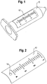
- FIG. 1 shows an injection syringe body 10 with a carrier foil 12, on which a scale is mounted.
- the injection-molded body 10 is hollow-cylindrical and has on one side a conical taper on which an injection needle is attached. At its other end, a flange can be seen, which facilitates the later handling of the syringe.
- the injection syringe body can also assume other shapes at its ends and, for example, also have no flange.
- Crucial for the invention are only the hollow cylindrical shape and the applied scale.
- the width of the carrier film 12 is about one third to one quarter of the circumference of the syringe body.
- the length of the injection syringe body is approximately between 5 and 15 cm, its diameter is correspondingly approximately between 1 and 3 cm.
- FIG. 2 shows the carrier film 12, on which the scale is already applied, for example by screen printing. At one end, under the measure 4, an opening 14 can be seen. The importance of the opening 14 will be discussed below.
- the carrier sheet 12 shown is already preformed so that it conforms better to the inner wall of an injection mold.
- FIG. 3 shows a detail of a cross section through an injection mold 16.
- a cavity 18 has the shape of the injection syringe body 10 to be produced. It can be seen already inserted carrier film 12.
- FIG. 3a is an enlarged detail FIG. 3 to see.
- the support film 12, which is also cut, lies in a recess 20. As can be seen in the detail magnification, it protrudes into the cavity 18, since the depth of the recess corresponds to only a fraction of the thickness of the carrier film 12.
- FIG. 4 shows a section through a syringe body 22 of another embodiment. Only in the detail enlargement in FIG. 4a is the to recognize applied carrier sheet 12. At the point where the hollow cylindrical part of the injection syringe body 22 merges into a conical shape, there is a step 24. An edge of the carrier foil 12 is aligned with the step 24. The corresponding inverse step of the injection mold with which the injection syringe body 22 is made serves as Stop for the carrier film 12 when inserting the same in the mold.
- the choice of the injection point helps to avoid a washing away or slippage of the carrier film 12, which does not cover the entire shaping surface of the injection mold.
- the preferred injection point is represented symbolically.
- a spray nozzle 28 is shown schematically.
- the injection mold is not shown, in which the injection syringe body 26 is injection-molded.
- the carrier film 12 has an opening 14, the opening 14 is arranged in alignment with the injection channel of the spray nozzle 28, so that during injection, the injected plastic material passes through the opening 14.
- the opening 14 is located in the vicinity of the flange facing edge of the carrier film 12 and substantially centrally to their longitudinal edges.
Description
Die Erfindung betrifft ein Verfahren zur Herstellung eines hohlzylinderförmigen Injektionsspritzenkörpers durch Spritzgießen sowie einen durch dieses Verfahren hergestellten Injektionsspritzenkörper. Der Spritzenkörper ist mit einer in Längsrichtung angebrachten Skala versehen. Die Erfindung betrifft ferner eine Spritzgießform zur Herstellung eines Injektionsspritzenkörpers.The invention relates to a method for producing a hollow-cylindrical injection-molded body by injection molding and to a syringe body produced by this method. The syringe body is provided with a longitudinally mounted scale. The invention further relates to an injection mold for producing a syringe body.
Injektionsspritzen bestehen aus einem Spritzenkörper und einem darin beweglichen Kolben. Insbesondere bei den sogenannten Einwegspritzen besteht der Spritzenkörper aus einem Kunststoff und wird kostengünstig durch Spritzgießen als Massenartikel hergestellt. Zum Dosieren des zu injizierenden Medikaments muß der Injektionsspritzenkörper mit einer in Längsrichtung angebrachten Skala versehen sein.Injection syringes consist of a syringe body and a piston movable therein. In particular, in the so-called disposable syringes, the syringe body is made of a plastic and is produced inexpensively by injection molding as a mass-produced article. In order to dose the medicament to be injected, the syringe body must be provided with a graduated scale.
Die Meßskala kann durch Bedrucken aufgebracht werden. Die Meßskala kann alternativ von außen auf den Spritzenkörper aufgeklebt werden. In beiden Fällen ist ein Arbeitsschritt im Anschluß an den Spritzgießprozeß erforderlich.The measuring scale can be applied by printing. The measuring scale can alternatively be glued to the syringe body from the outside. In both cases, a step following the injection molding process is required.
Aus der
Da Injektionsspritzen Massenartikel sind, besteht ein Bedarf an einem Verfahren, mit dem Injektionsspritzenkörper ohne Aufwand mit einer Skala versehen werden können.Since hypodermic syringes are mass-produced articles, there is a need for a method whereby a hypodermic body can be scaled easily.
Die Erfindung stellt ein Verfahren mit den Merkmalen des Anspruchs 1 bereit, bei dem eine Skala zunächst auf einer dünnen Trägerfolie aufgebracht wird und die Trägerfolie mit der Skala vor dem Spritzen in die Spritzgießform eingelegt wird wobei die Trägerfolie von der Kunststoffmasse an die Innenwand der Spritzgießform angedrückt wird. Das Bedrucken von Folie ist eine gut beherrschte Technik, mit der schnell eine dauerhafte Bedruckung erreicht wird. Das Einlegen der Trägerfolie in die Gießform kann leicht in den Gußprozeß integriert werden und erfolgt beispielsweise unmittelbar nachdem der jeweils zuvor gefertigte Spritzenkörper entformt wurde.The invention provides a method with the features of claim 1, wherein a scale is first applied to a thin carrier film and the carrier film is inserted with the scale before spraying into the injection mold, wherein the carrier film is pressed by the plastic compound to the inner wall of the injection mold becomes. Foil printing is a well-controlled technique that quickly achieves durable printing. The insertion of the carrier film in the mold can be easily integrated into the casting process and takes place, for example, immediately after the respective previously manufactured syringe body was removed from the mold.
Vorzugsweise ist in die formgebende Fläche der Spritzgießform eine Ausrichtstruktur eingearbeitet, mit deren Hilfe die Trägerfolie präzise positioniert wird. Die Ausrichtstruktur ist dabei in einer bevorzugten Ausführungsform eine flache Ausnehmung, deren Form der Außenkontur der Trägerfolie entspricht, vorzugsweise ist die Ausnehmung einen Bruchteil der Dicke der Trägerfolie tief. Die eingelegte Trägerfolie ragt also beim Spritzvorgang in die Kunststoffmasse hinein und wird so am fertigen Injektionsspritzenkörper sicher gehalten.Preferably, an alignment structure is incorporated into the shaping surface of the injection mold, with the help of which the carrier film precisely positioned becomes. The alignment structure is in a preferred embodiment, a flat recess whose shape corresponds to the outer contour of the carrier film, preferably, the recess is a fraction of the thickness of the carrier film deep. The inserted carrier film therefore projects into the plastic compound during the injection process and is thus held securely on the finished injection-molded body.
Alternativ kann in die formgebende Fläche der Spritzgießform wenigstens ein Anschlag eingearbeitet sein, an dem die Trägerfolie ausgerichtet wird. Dieser Anschlag ist vorzugsweise eine Stufe, so daß die Trägerfolie bis zur Anlage an dieser Stufe geschoben werden kann.Alternatively, at least one stop can be incorporated in the shaping surface of the injection mold, on which the carrier film is aligned. This stop is preferably a step, so that the carrier film can be pushed to the plant at this stage.
Bei einer vorteilhaften Ausführungsform wird die Trägerfolie vor dem Einlegen in die Spritzgießform entsprechend deren Innenradius vorgeformt.In an advantageous embodiment, the carrier film is preformed prior to insertion into the injection mold according to its inner radius.
Beim Spritzgießen wird der Kunststoff in flüssiger Form in die Spritzgießform gespritzt. Der Strom des flüssigen Kunststoffs kann die eingelegte Trägerfolie gegen ein Verschieben während des Einspritzvorgangs sichern, wenn der Einspritzort in Bezug auf die Trägerfolie geschickt gewählt wird. Vorzugsweise ist die Trägerfolie mit einer Öffnung ausgebildet, und die Öffnung ist mit dem Anspritzkanal fluchtend angeordnet, so daß beim Spritzen die eingespritzte Kunststoffmasse die Öffnung durchquert. Die eingespritzte Kunststoffmasse umströmt dann den Kern der Spritzgießform zuerst in einer Richtung weg von der Trägerfolie und baut dann einen Druck auf, durch den die Trägerfolie an die Innenfläche der Form angepreßt und somit lagefixiert wird.In injection molding, the plastic is injected in liquid form into the injection mold. The flow of the liquid plastic can secure the inserted carrier film against displacement during the injection process, if the injection location is selected skillfully with respect to the carrier film. Preferably, the carrier film is formed with an opening, and the opening is arranged in alignment with the Anspritzkanal, so that during injection, the injected plastic material passes through the opening. The injected plastic mass then flows around the core of the injection mold first in a direction away from the carrier film and then builds up a pressure through which the carrier film is pressed against the inner surface of the mold and thus fixed in position.
Weitere Vorteile des erfindungsgemäßen Verfahrens werden durch die nachstehende Beschreibung bevorzugter Ausführungsformen anhand der beigefügten Zeichnung deutlich. Hierbei zeigen:
-
Figur 1 einen nach dem erfindungsgemäßen Verfahren hergestellten Injektionsspritzenkörper; -
Figur 2 eine dünne Trägerfolie mit aufgebrachter Skala; -
Figur 3 -
Figur 3a eine Detailvergrößerung derFigur 3 -
Figur 4 eine teilweisen Querschnitt durch einen Injektionsspritzenkörper gemäß einer weiteren Ausführungsform mit Trägerfolie an einem Anschlag; -
Figur 4a eine Detailvergrößerung derFigur 4 zur Verdeutlichung einer Stufe; -
Figur 5 eine schematische Darstellung der Positionierung der Einspritzdüse im Verhältnis zum fertigen Injektionsspritzenkörper.
-
FIG. 1 an injection syringe body made by the method of the invention; -
FIG. 2 a thin carrier film with applied scale; -
FIG. 3 a partial cross section through an injection mold with inserted carrier film in a recess; -
FIG. 3a an enlarged detail of theFIG. 3 to clarify the recess -
FIG. 4 a partial cross-section through a syringe body according to another embodiment with carrier foil on a stop; -
FIG. 4a an enlarged detail of theFIG. 4 to illustrate a step; -
FIG. 5 a schematic representation of the positioning of the injection nozzle in relation to the finished injection syringe body.
Neben der Ausnehmung 20 bzw. der Stufe 24 hilft die Wahl des Einspritzpunktes, ein Wegspülen oder Verrutschen der Trägerfolie 12, die nicht die ganze formgebende Fläche der Spritzgießform bedeckt, zu vermeiden. In
Claims (10)
- A method of producing, by injection molding, a hollow cylindrical syringe body (10, 22, 26) which is provided with a scale fitted in the longitudinal direction,
the scale being applied to a thin carrier film (12), and the carrier film (12) with the scale being inserted into the injection mold (16) prior to the injection molding process, characterized in that
the carrier film (12) is pressed against the inner wall of the injection mold (16) by the plastic composition. - The method according to claim 1, characterized in that the carrier film (12) is accurately positioned in the injection mold by alignment structures incorporated in the shaping surface of the injection mold.
- The method according to claim 2, characterized in that the shaping surface has a flat recess (20) incorporated therein having a shape that corresponds to the outer contour of the carrier film (12), and the carrier film is inserted into the recess.
- The method according to claim 3, characterized in that the depth of the recess (20) corresponds to a fraction of the thickness of the carrier film (12).
- The method according to claim 2, characterized in that the shaping surface has at least one stop (24) incorporated therein and the carrier film (12) is aligned by means of this stop.
- The method according to claim 5, characterized in that the stop is made in the form of a step (24).
- The method according to any of the preceding claims, characterized in that the carrier film (12) is made to have an opening (14) and the opening (14) is arranged in alignment with the runner, so that in the injection molding process the plastic composition that is injected traverses the opening (14).
- The method according to any of the preceding claims, characterized in that the carrier film (12) is preformed before being inserted into the injection mold.
- A syringe body, produced by means of the method according to any of claims 1 to 8.
- An injection mold for producing a syringe body (10, 22, 26) having a shaping surface, characterized in that the shaping surface has a flat recess (20) incorporated therein, that an injection opening is disposed in the flat recess, and that the shape of the outer contour of the recess corresponds to a carrier film (12) which is inserted into the flat recess.
Applications Claiming Priority (2)
| Application Number | Priority Date | Filing Date | Title |
|---|---|---|---|
| DE102006047670A DE102006047670A1 (en) | 2006-10-09 | 2006-10-09 | syringe body |
| PCT/EP2007/008759 WO2008043516A1 (en) | 2006-10-09 | 2007-10-09 | Syringe body |
Publications (2)
| Publication Number | Publication Date |
|---|---|
| EP2106333A1 EP2106333A1 (en) | 2009-10-07 |
| EP2106333B1 true EP2106333B1 (en) | 2019-01-02 |
Family
ID=38728791
Family Applications (1)
| Application Number | Title | Priority Date | Filing Date |
|---|---|---|---|
| EP07818832.3A Not-in-force EP2106333B1 (en) | 2006-10-09 | 2007-10-09 | Syringe body |
Country Status (5)
| Country | Link |
|---|---|
| US (1) | US20100096773A1 (en) |
| EP (1) | EP2106333B1 (en) |
| JP (1) | JP2010505668A (en) |
| DE (1) | DE102006047670A1 (en) |
| WO (1) | WO2008043516A1 (en) |
Families Citing this family (6)
| Publication number | Priority date | Publication date | Assignee | Title |
|---|---|---|---|---|
| US9474861B2 (en) * | 2009-03-31 | 2016-10-25 | Sanofi-Aventis Deutschland Gmbh | Drug delivery device body |
| WO2012155056A1 (en) * | 2011-05-11 | 2012-11-15 | Isto Technologies, Inc. | Injection pressure monitoring device and system |
| FR2994851B1 (en) * | 2012-09-04 | 2015-08-21 | Rexam Healthcare La Verpillier | APPARATUS FOR INJECTING PHARMACEUTICAL LIQUID CONFIGURED TO BE PRE-FILLED |
| FR3005597B1 (en) * | 2013-05-16 | 2015-08-21 | Stiplastics | PROCESS FOR MANUFACTURING A TUBULAR OBJECT COATED WITH A FUNCTIONALIZATION FILM, AND OBJECT OBTAINED THEREBY |
| EP3449963B1 (en) | 2016-04-25 | 2023-09-27 | Terumo Kabushiki Kaisha | Syringe barrel for pre-filled syringe, syringe system, and pre-filled syringe |
| DE102018108549B4 (en) * | 2018-04-11 | 2022-01-05 | Gerresheimer Regensburg Gmbh | Method for producing an injection device with a bypass channel and a tool therefor |
Family Cites Families (5)
| Publication number | Priority date | Publication date | Assignee | Title |
|---|---|---|---|---|
| NZ244576A (en) * | 1989-02-08 | 1994-11-25 | Becton Dickinson Co | Syringe barrel with contrast band opposite indicia to improve readability |
| US5604006A (en) * | 1992-01-24 | 1997-02-18 | Cascade Engineering | Label inmolding process and article of manufacture produced therefrom |
| US5759494A (en) * | 1995-10-05 | 1998-06-02 | Corning Incorporated | Microplates which prevent optical cross-talk between wells |
| US6120481A (en) * | 1998-12-21 | 2000-09-19 | Becton, Dickinson And Company | Scale on a plastic syringe |
| US6966897B2 (en) * | 2000-09-22 | 2005-11-22 | Arte Corporation | Combined container-syringe and assembly method of the same |
-
2006
- 2006-10-09 DE DE102006047670A patent/DE102006047670A1/en not_active Withdrawn
-
2007
- 2007-10-09 WO PCT/EP2007/008759 patent/WO2008043516A1/en active Application Filing
- 2007-10-09 EP EP07818832.3A patent/EP2106333B1/en not_active Not-in-force
- 2007-10-09 US US12/311,651 patent/US20100096773A1/en not_active Abandoned
- 2007-10-09 JP JP2009531759A patent/JP2010505668A/en active Pending
Non-Patent Citations (1)
| Title |
|---|
| None * |
Also Published As
| Publication number | Publication date |
|---|---|
| EP2106333A1 (en) | 2009-10-07 |
| DE102006047670A1 (en) | 2008-04-10 |
| WO2008043516A1 (en) | 2008-04-17 |
| JP2010505668A (en) | 2010-02-25 |
| US20100096773A1 (en) | 2010-04-22 |
Similar Documents
| Publication | Publication Date | Title |
|---|---|---|
| EP2106333B1 (en) | Syringe body | |
| EP2731647B1 (en) | Multi-chamber syringe | |
| DE2140311C3 (en) | Hose end piece and device for producing the same | |
| DE3834917A1 (en) | NOZZLE FOR INJECTION MOLDING MACHINES | |
| EP2505332B1 (en) | Plastic body and system for producing the plastic body | |
| DE102005005468B4 (en) | syringe | |
| EP3606719A1 (en) | Injection-moulding tool and method for producing an injection-moulded product with a long, thin channel | |
| DE2854647A1 (en) | METHOD AND DEVICE FOR MEASURING AND DISPENSING A PRE-DETERMINED QUANTITY OF LIQUID | |
| DE202014100008U1 (en) | Threaded insert for an injection molded part and injection molded part | |
| DE3820348A1 (en) | METHOD AND DEVICE FOR PRODUCING A HOUSING FOR A SENSOR AND CATHETER WITH SENSOR HOUSING | |
| WO1998006556A1 (en) | Injection molding form and process for producing hollow parts | |
| DE102013208541A1 (en) | Detection device and method for producing a detection device | |
| DE102014201380B4 (en) | Process for producing a fiber-reinforced hollow profile component | |
| WO1993010849A1 (en) | Canula, in particular for vascular puncture | |
| DE102009010950A1 (en) | Lamella for use as e.g. screen, in ventilation nozzle of vehicle, has bearing element comprising inner lying core that is extended over entire length of bearing element and coated by surrounding layer | |
| DE2200740A1 (en) | CORE FOR PIPE ELBOWS MADE OF PLASTIC | |
| EP2557644A2 (en) | Aide à l'introduction pour câble | |
| AT403676B (en) | HOLLOW MOLD FOR THE PRODUCTION OF HOLLOW BODIES WITH HANDLE TIPS FROM THERMOPLASTIC MATERIAL | |
| DE102016225535B4 (en) | Device and method for molding an elongated insert by means of centering | |
| DE102007015216B4 (en) | Device and method for producing a hollow body from at least two layers of plastic | |
| EP2801465A2 (en) | Method for producing a container with a flexible inner bag | |
| DE2929075A1 (en) | METHOD AND DEVICE FOR PREVENTING A DROP LEAK FROM A PLASTIC INJECTION MOLD | |
| DE10328692A1 (en) | Connecting element e.g. for motor vehicle construction, uses clamping body for limiting installation depth via shoulder or collar | |
| DE102004040358A1 (en) | Method for producing an indwelling catheter and indwelling catheter | |
| DE102017119345A1 (en) | Adapter element for attaching a needle tip to a syringe body |
Legal Events
| Date | Code | Title | Description |
|---|---|---|---|
| PUAI | Public reference made under article 153(3) epc to a published international application that has entered the european phase |
Free format text: ORIGINAL CODE: 0009012 |
|
| 17P | Request for examination filed |
Effective date: 20090508 |
|
| AK | Designated contracting states |
Kind code of ref document: A1 Designated state(s): AT BE BG CH CY CZ DE DK EE ES FI FR GB GR HU IE IS IT LI LT LU LV MC MT NL PL PT RO SE SI SK TR |
|
| DAX | Request for extension of the european patent (deleted) | ||
| 17Q | First examination report despatched |
Effective date: 20130715 |
|
| STAA | Information on the status of an ep patent application or granted ep patent |
Free format text: STATUS: EXAMINATION IS IN PROGRESS |
|
| GRAP | Despatch of communication of intention to grant a patent |
Free format text: ORIGINAL CODE: EPIDOSNIGR1 |
|
| STAA | Information on the status of an ep patent application or granted ep patent |
Free format text: STATUS: GRANT OF PATENT IS INTENDED |
|
| INTG | Intention to grant announced |
Effective date: 20180301 |
|
| RIC1 | Information provided on ipc code assigned before grant |
Ipc: B29C 45/14 20060101AFI20180216BHEP Ipc: A61M 5/31 20060101ALI20180216BHEP Ipc: B29L 31/00 20060101ALI20180216BHEP Ipc: B29C 45/26 20060101ALI20180216BHEP |
|
| GRAS | Grant fee paid |
Free format text: ORIGINAL CODE: EPIDOSNIGR3 |
|
| GRAA | (expected) grant |
Free format text: ORIGINAL CODE: 0009210 |
|
| STAA | Information on the status of an ep patent application or granted ep patent |
Free format text: STATUS: THE PATENT HAS BEEN GRANTED |
|
| AK | Designated contracting states |
Kind code of ref document: B1 Designated state(s): AT BE BG CH CY CZ DE DK EE ES FI FR GB GR HU IE IS IT LI LT LU LV MC MT NL PL PT RO SE SI SK TR |
|
| REG | Reference to a national code |
Ref country code: GB Ref legal event code: FG4D Free format text: NOT ENGLISH |
|
| REG | Reference to a national code |
Ref country code: CH Ref legal event code: EP Ref country code: AT Ref legal event code: REF Ref document number: 1083786 Country of ref document: AT Kind code of ref document: T Effective date: 20190115 |
|
| REG | Reference to a national code |
Ref country code: IE Ref legal event code: FG4D Free format text: LANGUAGE OF EP DOCUMENT: GERMAN |
|
| REG | Reference to a national code |
Ref country code: DE Ref legal event code: R096 Ref document number: 502007016549 Country of ref document: DE |
|
| REG | Reference to a national code |
Ref country code: NL Ref legal event code: MP Effective date: 20190102 |
|
| REG | Reference to a national code |
Ref country code: LT Ref legal event code: MG4D |
|
| PG25 | Lapsed in a contracting state [announced via postgrant information from national office to epo] |
Ref country code: NL Free format text: LAPSE BECAUSE OF FAILURE TO SUBMIT A TRANSLATION OF THE DESCRIPTION OR TO PAY THE FEE WITHIN THE PRESCRIBED TIME-LIMIT Effective date: 20190102 |
|
| PG25 | Lapsed in a contracting state [announced via postgrant information from national office to epo] |
Ref country code: PT Free format text: LAPSE BECAUSE OF FAILURE TO SUBMIT A TRANSLATION OF THE DESCRIPTION OR TO PAY THE FEE WITHIN THE PRESCRIBED TIME-LIMIT Effective date: 20190502 Ref country code: ES Free format text: LAPSE BECAUSE OF FAILURE TO SUBMIT A TRANSLATION OF THE DESCRIPTION OR TO PAY THE FEE WITHIN THE PRESCRIBED TIME-LIMIT Effective date: 20190102 Ref country code: PL Free format text: LAPSE BECAUSE OF FAILURE TO SUBMIT A TRANSLATION OF THE DESCRIPTION OR TO PAY THE FEE WITHIN THE PRESCRIBED TIME-LIMIT Effective date: 20190102 Ref country code: LT Free format text: LAPSE BECAUSE OF FAILURE TO SUBMIT A TRANSLATION OF THE DESCRIPTION OR TO PAY THE FEE WITHIN THE PRESCRIBED TIME-LIMIT Effective date: 20190102 Ref country code: SE Free format text: LAPSE BECAUSE OF FAILURE TO SUBMIT A TRANSLATION OF THE DESCRIPTION OR TO PAY THE FEE WITHIN THE PRESCRIBED TIME-LIMIT Effective date: 20190102 Ref country code: FI Free format text: LAPSE BECAUSE OF FAILURE TO SUBMIT A TRANSLATION OF THE DESCRIPTION OR TO PAY THE FEE WITHIN THE PRESCRIBED TIME-LIMIT Effective date: 20190102 |
|
| PG25 | Lapsed in a contracting state [announced via postgrant information from national office to epo] |
Ref country code: BG Free format text: LAPSE BECAUSE OF FAILURE TO SUBMIT A TRANSLATION OF THE DESCRIPTION OR TO PAY THE FEE WITHIN THE PRESCRIBED TIME-LIMIT Effective date: 20190402 Ref country code: LV Free format text: LAPSE BECAUSE OF FAILURE TO SUBMIT A TRANSLATION OF THE DESCRIPTION OR TO PAY THE FEE WITHIN THE PRESCRIBED TIME-LIMIT Effective date: 20190102 Ref country code: IS Free format text: LAPSE BECAUSE OF FAILURE TO SUBMIT A TRANSLATION OF THE DESCRIPTION OR TO PAY THE FEE WITHIN THE PRESCRIBED TIME-LIMIT Effective date: 20190502 Ref country code: GR Free format text: LAPSE BECAUSE OF FAILURE TO SUBMIT A TRANSLATION OF THE DESCRIPTION OR TO PAY THE FEE WITHIN THE PRESCRIBED TIME-LIMIT Effective date: 20190403 |
|
| REG | Reference to a national code |
Ref country code: DE Ref legal event code: R097 Ref document number: 502007016549 Country of ref document: DE |
|
| PG25 | Lapsed in a contracting state [announced via postgrant information from national office to epo] |
Ref country code: EE Free format text: LAPSE BECAUSE OF FAILURE TO SUBMIT A TRANSLATION OF THE DESCRIPTION OR TO PAY THE FEE WITHIN THE PRESCRIBED TIME-LIMIT Effective date: 20190102 Ref country code: IT Free format text: LAPSE BECAUSE OF FAILURE TO SUBMIT A TRANSLATION OF THE DESCRIPTION OR TO PAY THE FEE WITHIN THE PRESCRIBED TIME-LIMIT Effective date: 20190102 Ref country code: DK Free format text: LAPSE BECAUSE OF FAILURE TO SUBMIT A TRANSLATION OF THE DESCRIPTION OR TO PAY THE FEE WITHIN THE PRESCRIBED TIME-LIMIT Effective date: 20190102 Ref country code: SK Free format text: LAPSE BECAUSE OF FAILURE TO SUBMIT A TRANSLATION OF THE DESCRIPTION OR TO PAY THE FEE WITHIN THE PRESCRIBED TIME-LIMIT Effective date: 20190102 Ref country code: CZ Free format text: LAPSE BECAUSE OF FAILURE TO SUBMIT A TRANSLATION OF THE DESCRIPTION OR TO PAY THE FEE WITHIN THE PRESCRIBED TIME-LIMIT Effective date: 20190102 Ref country code: RO Free format text: LAPSE BECAUSE OF FAILURE TO SUBMIT A TRANSLATION OF THE DESCRIPTION OR TO PAY THE FEE WITHIN THE PRESCRIBED TIME-LIMIT Effective date: 20190102 |
|
| PLBE | No opposition filed within time limit |
Free format text: ORIGINAL CODE: 0009261 |
|
| STAA | Information on the status of an ep patent application or granted ep patent |
Free format text: STATUS: NO OPPOSITION FILED WITHIN TIME LIMIT |
|
| 26N | No opposition filed |
Effective date: 20191003 |
|
| PG25 | Lapsed in a contracting state [announced via postgrant information from national office to epo] |
Ref country code: SI Free format text: LAPSE BECAUSE OF FAILURE TO SUBMIT A TRANSLATION OF THE DESCRIPTION OR TO PAY THE FEE WITHIN THE PRESCRIBED TIME-LIMIT Effective date: 20190102 |
|
| PG25 | Lapsed in a contracting state [announced via postgrant information from national office to epo] |
Ref country code: TR Free format text: LAPSE BECAUSE OF FAILURE TO SUBMIT A TRANSLATION OF THE DESCRIPTION OR TO PAY THE FEE WITHIN THE PRESCRIBED TIME-LIMIT Effective date: 20190102 |
|
| REG | Reference to a national code |
Ref country code: DE Ref legal event code: R119 Ref document number: 502007016549 Country of ref document: DE |
|
| PG25 | Lapsed in a contracting state [announced via postgrant information from national office to epo] |
Ref country code: MC Free format text: LAPSE BECAUSE OF FAILURE TO SUBMIT A TRANSLATION OF THE DESCRIPTION OR TO PAY THE FEE WITHIN THE PRESCRIBED TIME-LIMIT Effective date: 20190102 |
|
| REG | Reference to a national code |
Ref country code: CH Ref legal event code: PL |
|
| PG25 | Lapsed in a contracting state [announced via postgrant information from national office to epo] |
Ref country code: CH Free format text: LAPSE BECAUSE OF NON-PAYMENT OF DUE FEES Effective date: 20191031 Ref country code: LI Free format text: LAPSE BECAUSE OF NON-PAYMENT OF DUE FEES Effective date: 20191031 Ref country code: DE Free format text: LAPSE BECAUSE OF NON-PAYMENT OF DUE FEES Effective date: 20200501 Ref country code: LU Free format text: LAPSE BECAUSE OF NON-PAYMENT OF DUE FEES Effective date: 20191009 |
|
| REG | Reference to a national code |
Ref country code: BE Ref legal event code: MM Effective date: 20191031 |
|
| PG25 | Lapsed in a contracting state [announced via postgrant information from national office to epo] |
Ref country code: BE Free format text: LAPSE BECAUSE OF NON-PAYMENT OF DUE FEES Effective date: 20191031 |
|
| GBPC | Gb: european patent ceased through non-payment of renewal fee |
Effective date: 20191009 |
|
| PG25 | Lapsed in a contracting state [announced via postgrant information from national office to epo] |
Ref country code: FR Free format text: LAPSE BECAUSE OF NON-PAYMENT OF DUE FEES Effective date: 20191031 Ref country code: GB Free format text: LAPSE BECAUSE OF NON-PAYMENT OF DUE FEES Effective date: 20191009 Ref country code: IE Free format text: LAPSE BECAUSE OF NON-PAYMENT OF DUE FEES Effective date: 20191009 |
|
| REG | Reference to a national code |
Ref country code: AT Ref legal event code: MM01 Ref document number: 1083786 Country of ref document: AT Kind code of ref document: T Effective date: 20191009 |
|
| PG25 | Lapsed in a contracting state [announced via postgrant information from national office to epo] |
Ref country code: AT Free format text: LAPSE BECAUSE OF NON-PAYMENT OF DUE FEES Effective date: 20191009 |
|
| PG25 | Lapsed in a contracting state [announced via postgrant information from national office to epo] |
Ref country code: CY Free format text: LAPSE BECAUSE OF FAILURE TO SUBMIT A TRANSLATION OF THE DESCRIPTION OR TO PAY THE FEE WITHIN THE PRESCRIBED TIME-LIMIT Effective date: 20190102 |
|
| PG25 | Lapsed in a contracting state [announced via postgrant information from national office to epo] |
Ref country code: MT Free format text: LAPSE BECAUSE OF FAILURE TO SUBMIT A TRANSLATION OF THE DESCRIPTION OR TO PAY THE FEE WITHIN THE PRESCRIBED TIME-LIMIT Effective date: 20190102 Ref country code: HU Free format text: LAPSE BECAUSE OF FAILURE TO SUBMIT A TRANSLATION OF THE DESCRIPTION OR TO PAY THE FEE WITHIN THE PRESCRIBED TIME-LIMIT; INVALID AB INITIO Effective date: 20071009 |