EP2106052A2 - Communication system, transmitting apparatus, receiving apparatus, communication method and record medium for transferring a clock in a packet network - Google Patents
Communication system, transmitting apparatus, receiving apparatus, communication method and record medium for transferring a clock in a packet network Download PDFInfo
- Publication number
- EP2106052A2 EP2106052A2 EP20090156122 EP09156122A EP2106052A2 EP 2106052 A2 EP2106052 A2 EP 2106052A2 EP 20090156122 EP20090156122 EP 20090156122 EP 09156122 A EP09156122 A EP 09156122A EP 2106052 A2 EP2106052 A2 EP 2106052A2
- Authority
- EP
- European Patent Office
- Prior art keywords
- time
- time stamp
- stamp packet
- packet
- sending
- Prior art date
- Legal status (The legal status is an assumption and is not a legal conclusion. Google has not performed a legal analysis and makes no representation as to the accuracy of the status listed.)
- Withdrawn
Links
Images


Classifications
-
- H—ELECTRICITY
- H04—ELECTRIC COMMUNICATION TECHNIQUE
- H04L—TRANSMISSION OF DIGITAL INFORMATION, e.g. TELEGRAPHIC COMMUNICATION
- H04L47/00—Traffic control in data switching networks
- H04L47/10—Flow control; Congestion control
- H04L47/22—Traffic shaping
-
- H—ELECTRICITY
- H04—ELECTRIC COMMUNICATION TECHNIQUE
- H04J—MULTIPLEX COMMUNICATION
- H04J3/00—Time-division multiplex systems
- H04J3/02—Details
- H04J3/06—Synchronising arrangements
- H04J3/0635—Clock or time synchronisation in a network
- H04J3/0638—Clock or time synchronisation among nodes; Internode synchronisation
- H04J3/0658—Clock or time synchronisation among packet nodes
- H04J3/0661—Clock or time synchronisation among packet nodes using timestamps
- H04J3/0664—Clock or time synchronisation among packet nodes using timestamps unidirectional timestamps
-
- H—ELECTRICITY
- H04—ELECTRIC COMMUNICATION TECHNIQUE
- H04L—TRANSMISSION OF DIGITAL INFORMATION, e.g. TELEGRAPHIC COMMUNICATION
- H04L47/00—Traffic control in data switching networks
- H04L47/10—Flow control; Congestion control
-
- H—ELECTRICITY
- H04—ELECTRIC COMMUNICATION TECHNIQUE
- H04J—MULTIPLEX COMMUNICATION
- H04J3/00—Time-division multiplex systems
- H04J3/02—Details
- H04J3/06—Synchronising arrangements
- H04J3/0635—Clock or time synchronisation in a network
- H04J3/0638—Clock or time synchronisation among nodes; Internode synchronisation
- H04J3/0658—Clock or time synchronisation among packet nodes
- H04J3/0673—Clock or time synchronisation among packet nodes using intermediate nodes, e.g. modification of a received timestamp before further transmission to the next packet node, e.g. including internal delay time or residence time into the packet
Definitions
- the present invention relates to a communication system, a transmitting apparatus, a receiving apparatus, a communication method, and a record medium, and more particularly relates to a technology for transferring a clock in a packet network.
- the network is going to shift to a packet network, being an asynchronous network, from a network for a TDM (Time Division Multiplexing) device.
- a packet network being an asynchronous network
- TDM Time Division Multiplexing
- the appliance for using a synchronous signal still lingers in the network signifies that propagation of a time signal, being a synchronous clock, is indispensable.
- the technology of packetizing and transmitting the time signal for example, see Patent document 1.
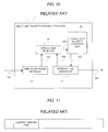
- the transmitting apparatus as shown in Fig. 9 can be listed as a time stamp packet transmitting apparatus relating to the present invention.
- This time stamp packet transmitting apparatus 3 includes a time stamp packet transmitter 31, and a sending cycle generator 32.
- the time stamp packet transmitter 31 of the time stamp packet transmitting apparatus 3 inputs a time information input 301 and a sending trigger 303. And, the time stamp packet transmitter 31 generates a time stamp packet 302 in which a current time has been filed, as shown in Fig. 11 , and outputs it to a packet network (not shown in the figure).
- the sending cycle generator 32 inputs the time information input 301, generates the sending trigger 303, and transmits it to the time stamp packet transmitter 31.
- This time stamp packet receiving apparatus 4 includes a time stamp packet receiver 41, and an arrival time detector 42, an internal time generator 43, and a correction quantity statistics unit 44.
- the time stamp packet receiver 41 extracts a reception trigger 403 from a time stamp packet 401 coming from the packet network, and outputs it.
- the arrival time detector 42 outputs a difference time 406 between the reception trigger 403 coming from the time stamp packet receiver 41, and an internal time 404 coming from the internal time generator 43 to the correction quantity statistics unit 44.
- the internal time generator 43 inputs a correction time 405 coming from the correction quantity statistics unit 44, and outputs the internal time 404 to the arrival time detector 42. Further, the internal time generator 43 outputs an internal time 402 to the outside.
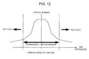
- the correction quantity statistics unit 44 subject the difference time 406 coming from the arrival time detector 42 to a statistics process, and gains a distribution of the difference times as shown in Fig. 12 . And, the correction quantity statistics unit 44 generates the correction time 405 based upon the above distribution, and outputs it the internal time generator 43.
- Patent document 1 JP-P2007-104347A
- a periodic dispersion time of a delay occurs due to a protocol transform, a format transform, etc. that the appliances constituting the packet network use.
- This periodic fluctuation is described in ITU-T (International Telecommunication Union-Telecommunication Standardization Sector) G. 8261
- an exemplary object of the present invention lies in a point of eliminating the above-mentioned points at issue, and providing a technology capable of transmitting time information in the packet network without being effected by the periodic dispersion time of a delay.
- the time stamp packet communication system in accordance with the present invention includes a time stamp packet transmitting apparatus including a changer for changing a sending time period of a time stamp packet for filing time information, and a transmission unit for transmitting the time stamp packet at its changed sending time period to a time stamp packet receiving apparatus via a packet network.
- the time stamp packet transmitting apparatus in accordance with the present invention includes a changer for changing a sending time period of a time stamp packet for filing time information, and a transmission unit for transmitting the time stamp packet at its changed sending time period to a time stamp packet receiving apparatus via a packet network.
- the time stamp packet receiving apparatus in accordance with the present invention includes a classifier for making a frequency classification for a time stamp packet in which an absolute time of a transmission source and information indicative of a changed sending time period have been inserted, which is transmitted from the time stamp packet transmitting apparatus, from the above sending time period.
- the clock transfer method in accordance with the present invention includes a process of changing a sending time period of a time stamp packet for filing time information, and a transmission process of transmitting the time stamp packet at its changed sending time period to a time stamp packet receiving apparatus via a packet network in the time stamp packet transmitting apparatus side.
- the present invention makes it possible to transfer time information in the packet network without being effected by the periodic dispersion time of a delay by assuming a configuration and operation as mentioned above.
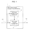
- Fig. 1 is a block diagram illustrating a configuration example of the time stamp packet transmitting apparatus in accordance with the embodiment of the present invention.
- a time stamp packet transmitting apparatus 1 includes a time stamp packet transmitter 11 and an arbitrary sending cycle generator 12.
- the time stamp packet transmitter 11 inputs time information 101 indicative of the current time, and a sending trigger 111. Further, the time stamp packet transmitter 11 outputs a time stamp packet 102 to a packet network 100.
- the arbitrary sending cycle generator 12 outputs to the time stamp packet transmitter 11 the sending trigger 111 generated so as to change a transmission time period based upon the time information 101.
- the time stamp packet transmitter 11 sends the time stamp packet 102 for filing time information at an arbitrary sending packet time period responding to the sending trigger 111 that is output from the arbitrary sending cycle generator 12, thereby making it possible to detect a periodic delay jitter frequency that occurs in the appliances within the packet network, and to remove the corresponding frequency.
- the time stamp packet it becomes possible to use the time stamp packet, thereby to make a synchronous clock transfer with a high precision through an asynchronous packet network.
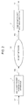
- Fig. 2 is a block diagram illustrating a configuration example of the time stamp packet communication system in accordance with the embodiment of the present invention.
- the time stamp packet communication system in accordance with the embodiment of the present invention includes a packet network 100, a time stamp packet transmitting apparatus 1, and a time stamp packet receiving apparatus 2.
- the time stamp packet transmitting apparatus 1 inputs time information 101, generates time stamp packet 102, and outputs it to the packet network 100.
- the time stamp packet receiving apparatus 2 inputs a time stamp packet 103 coming from the packet network 100, and outputs time information 104.
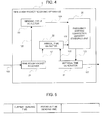
- Fig. 3 is a block diagram illustrating a detailed configuration example of the time stamp packet transmitting apparatus 1 in accordance with the embodiment of the present invention.
- the time stamp packet transmitting apparatus 1 includes a time stamp packet transmitter 11, an arbitrary sending cycle generator 12, a previous sending time holder 13, and a random number generator 14.
- the time stamp packet transmitter 11 inputs time information 101, a sending trigger 111 coming from the arbitrary sending cycle generator 12 and a previous-time sending time 112 coming from the previous sending time holder 13. Further, the time stamp packet transmitter 11 outputs a this-time sending time 113 to the previous sending time holder 13. In addition hereto, the time stamp packet transmitter 11 outputs a time stamp packet 102 to the packet network 100 with the sending trigger 111 as a turning point. In this time stamp packet 102, the time information 101 for defining an absolute time of a transmission source as a current sending time is inserted, and the previous-time sending time 112 is inserted for a purpose of calculating a sending time period of the time stamp packet.
- time stamp packet transmitter 11 inserts the current sending time 101 and the previous-time sending time 112 in the time stamp packet 102, it is enough to insert at least the current sending time 101 in the time stamp packet 102, and what is inserted is not limited hereto. However, the following explanation is made on the assumption that the time stamp packet transmitter 11 inserts the current sending time 101 and the previous-time sending time 112 in the time stamp packet 102.
- the previous sending time holder 13 inputs the this-time sending time 113 from the time stamp packet transmitter 11, and holds it. Further, the previous sending time holder 13 outputs the held this-time sending time as the previous-time sending time 112 to the time stamp packet transmitter 11.
- the arbitrary sending cycle generator 12 inputs the time information 101 and a random number 114 coming from the random number generator 14, and output the sending trigger 111 to the time stamp packet transmitter 11.
- the random number generator 14 generates the random number 114, and outputs it to the arbitrary sending cycle generator 12.
- Fig. 4 is a block diagram illustrating a detailed configuration example of the time stamp packet receiving apparatus 2 in accordance with the embodiment of the present invention.
- the time stamp packet receiving apparatus 2 includes a time stamp packet receiver 21, an arrival time detector 22, a sending cycle detector 23, an internal time generator 24, and a frequency sorting correction quantity statistics unit 25.
- the time stamp packet receiver 21 inputs a time stamp packet 103 that inputs from the packet network 100. Further, the time stamp packet receiver 21 outputs a previous-time/this-time sending time 126 extracted from the time stamp packet 103 to the sending cycle detector 23, and outputs a reception trigger 121 to the arrival time detector 22.
- the arrival time detector 22 generates a difference time 125 between the reception trigger 121 coming from the time stamp packet receiver 21 and an internal time 122 coming from the internal time generator 24, and outputs it to the frequency sorting correction quantity statistics unit 25.
- the sending cycle detector 23 inputs the previous-time/this-time sending time 126 coming from the time stamp packet receiver 21, and works out a sending cycle from a difference between the previous-time sending time and the this-time sending time. And, the sending cycle detector 23 outputs the worked-out sending cycle as a frequency identifier 124 to the frequency sorting correction quantity statistics unit 25. Additionally, when the time stamp packet transmitting apparatus has a configuration in which the previous-time sending time 112 is not inserted in the time stamp packet 102, the sending cycle detector 23 is configured to hold the sending time of the time stamp packet received previous time.
- the frequency sorting correction quantity statistics unit 25 generates a correction time 123 from the difference time 125 coming from the arrival time detector 22 and the frequency identifier 124 from the sending cycle detector 23, and outputs it to the internal time generator 24.
- the internal time generator 24 generates the internal time 122 based upon the correction time 123 coming from the frequency sorting correction quantity statistics unit 25, and outputs it to the arrival time detector 22. Further, the internal time generator 24 outputs an internal time 127 to the outside.
- Fig. 5 is a view illustrating a format of the time stamp packet in accordance with the embodiment of the present invention.
- the current sending time has been inserted as an absolute time of a transmission source, and the previous-time sending time has been inserted so as to calculate the sending time period of the time stamp packet.
- Fig. 6 is a view illustrating a distribution of difference times for each frequency subjected to a statistics process by the frequency sorting correction quantity statistics unit 25 of Fig. 4 .
- Fig. 7 is a flowchart illustrating a time stamp packet identification operation by the frequency sorting correction quantity statistics unit 25 of Fig. 4 .
- Fig. 8 is a flowchart illustrating a statistics process operation by the frequency sorting correction quantity statistics unit 25 of Fig. 4 .
- the time stamp packet transmitting apparatus 1 transmits the time information 101 (current sending time), being a this-time sending time of a transmission source, and the previous-time sending time 112 to the packet network 100.
- the time stamp packet transmitter 11 inputs the sending trigger 111 as frequency component information (sending time period) in order to retrieve a frequency fluctuation component that occurs in the packet network 100, and outputs the time stamp packet shown in Fig. 5 to the packet network 100.
- the previous sending holder 13 holds the previous-time sending time 112. Further, the arbitrary sending cycle generator 12 outputs the sending trigger 111 arbitrarily at a frequency (sending time period) such that the frequency fluctuation component occurring in the packet network 100 can be retrieved, thereby to retrieve the frequency fluctuation component.
- the random number generator 14 generates a random number 114 for smoothing and outputting an occurrence cycle of the sending trigger 111 as a range in which the frequency fluctuation component occurring in the packet network 100 is retrieved.
- the time stamp packet receiver 21 inputs the time stamp packet 103 from the packet network 100. And, the time stamp packet receiver 21 outputs the previous-time/this-time sending time 126 extracted from the time stamp packet 103 to the sending cycle detector 23, and outputs a reception trigger 121 to the arrival time detector 22.
- the sending cycle detector 23 inputs a previous-time/this-time sending time 126 extracted from the time stamp packet 103, and outputs a frequency identifier 124 to the frequency sorting correction quantity statistics unit 25.
- the arrival time detector 22 inputs the reception trigger 121 and the internal time 122, and outputs the difference time 125 to the frequency sorting correction quantity statistics unit 25.
- the frequency sorting correction quantity statistics unit 25 inputs the frequency identifier 124 and the difference time 125, and performs two operations, i.e. a statistics process operation shown in Fig. 8 and a time stamp packet identification operation shown in Fig. 7 . An operation of the frequency sorting correction quantity statistics unit 25 will be explained by making a reference to these Fig. 7 and Fig. 8 .
- the frequency sorting correction quantity statistics unit 25 makes a frequency sorting by use of the frequency identifier 124 coming from the sending cycle detector 23 (step S11 of Fig. 8 ), and collects a distribution of difference times 125 for each frequency, that is, takes the statistics of the frequency fluctuation for each frequency that occurs in the packet network 100 shown in Fig. 6 .
- the frequency sorting correction quantity statistics unit 25 computes a dispersion value (1 to n) for each frequency (1 to n+1) (step S12 of Fig. 8 ).
- the frequency sorting correction quantity statistics unit 25 detects an abnormal frequency band (sorting of the frequency that is not used) by using the dispersion value (1 to n) calculated for each frequency (1 to n+1) (step S13 of Fig. 8 ).
- the number of occurrence packets which is proportional to an occurrence quantity of information, largely viewing, is a random number, and does not include the frequency component. For this, originally, it is hardly possible that the dispersion time of a delay due to passage through the packet network 100 for handling this information includes the frequency component.
- a periodic dispersion time of a delay occurs due to a protocol transform, a format transform, etc. that the appliances constituting the packet network 100 use.
- This periodic dispersion time of a delay is defined as an abnormal frequency band.
- the frequency sorting correction quantity statistics unit 25 makes a frequency sorting by use of the frequency identifier 124 coming from the sending cycle detector 23.
- the frequency sorting correction quantity statistics unit 25 confirms that the frequency of the above packet is not an abnormal frequency determined in the first operation (it is a frequency that may be used) (step S1 of Fig. 7 ). When it is an abnormal frequency, the frequency sorting correction quantity statistics unit 25 does not perform the operation subsequent to it (step S4 of Fig. 7 ).
- the frequency sorting correction quantity statistics unit 25 outputs the correction time (step S3 of Fig. 7 ) when a difference time of the above packet is within an pre-decided arrival expectation value range (step S2 of Fig. 7 ). Further, it does not perform the operation subsequent to it (step S4 of Fig. 7 ) when a difference time of the above packet is out of an arrival expectation value range (step S2 of Fig. 7 ).
- the internal time generator 24 which is usually configured with PLL (Phase Locked Loop), generates the internal time 122 based upon the correction time 123 that is inputted from the frequency sorting correction quantity statistics unit 25, and outputs it.
- PLL Phase Locked Loop
- the time stamp packet transmitter 11 sends the time stamp packet 102 for filing time information at an arbitrary sending time period responding to the sending trigger 111 that is output from the arbitrary sending cycle generator 12, thereby enabling the time stamp packet receiving apparatus 2 to detect a periodic delay jitter frequency that occurs in the appliances within the packet network 100, and to remove the corresponding frequency.
- the time stamp packet transmitter 11 inserts the current sending time and an arbitrary sending packet time period (previous-time sending time) in the time stamp packet 102, thereby enabling the time stamp packet receiving apparatus 2 to detect a periodic delay jitter frequency that occurs in the appliances within the packet network 100, and to remove the corresponding frequency.
Abstract
An exemplary object of the present invention lies in a point of providing a time stamp packet transmitting apparatus capable of transferring time information in a packet network without being effected by a periodic dispersion time of a delay. The time stamp packet transmitting apparatus of the present invention is for changing a sending time period of a time stamp packet for filing time information, and transmitting the time stamp packet at its changed sending time period to a time stamp packet receiving apparatus via a packet network. In the present invention, sending the time stamp packet at an arbitrary sending packet time period responding to a sending trigger, which is output from an arbitrary sending cycle generator, makes it possible to detect a periodic delay jitter frequency that occurs in appliances within the packet network, and to remove the corresponding frequency.
Description
- This application is based upon and claims the benefit of priority from Japanese patent application No.
2008-079457, filed on March 26, 2008 - The present invention relates to a communication system, a transmitting apparatus, a receiving apparatus, a communication method, and a record medium, and more particularly relates to a technology for transferring a clock in a packet network.
- In recent years, the network is going to shift to a packet network, being an asynchronous network, from a network for a TDM (Time Division Multiplexing) device. However, the fact that the appliance for using a synchronous signal still lingers in the network signifies that propagation of a time signal, being a synchronous clock, is indispensable. For this, the technology of packetizing and transmitting the time signal (for example, see Patent document 1) is used.
- The transmitting apparatus as shown in
Fig. 9 can be listed as a time stamp packet transmitting apparatus relating to the present invention. This time stamppacket transmitting apparatus 3 includes a timestamp packet transmitter 31, and asending cycle generator 32. - The time
stamp packet transmitter 31 of the time stamppacket transmitting apparatus 3 inputs atime information input 301 and asending trigger 303. And, the timestamp packet transmitter 31 generates atime stamp packet 302 in which a current time has been filed, as shown inFig. 11 , and outputs it to a packet network (not shown in the figure). Herein, thesending cycle generator 32 inputs thetime information input 301, generates thesending trigger 303, and transmits it to the timestamp packet transmitter 31. - Further, the receiving apparatus shown in
Fig. 10 can be listed as a time stamp packet receiving apparatus relating to the present invention. This time stamppacket receiving apparatus 4 includes a timestamp packet receiver 41, and anarrival time detector 42, aninternal time generator 43, and a correctionquantity statistics unit 44. - In the time stamp
packet receiving apparatus 4, the timestamp packet receiver 41 extracts a reception trigger 403 from atime stamp packet 401 coming from the packet network, and outputs it. Thearrival time detector 42 outputs adifference time 406 between thereception trigger 403 coming from the timestamp packet receiver 41, and aninternal time 404 coming from theinternal time generator 43 to the correctionquantity statistics unit 44. - The
internal time generator 43 inputs acorrection time 405 coming from the correctionquantity statistics unit 44, and outputs theinternal time 404 to thearrival time detector 42. Further, theinternal time generator 43 outputs aninternal time 402 to the outside. The correctionquantity statistics unit 44 subject thedifference time 406 coming from thearrival time detector 42 to a statistics process, and gains a distribution of the difference times as shown inFig. 12 . And, the correctionquantity statistics unit 44 generates thecorrection time 405 based upon the above distribution, and outputs it theinternal time generator 43. - In the above-mentioned
Patent document 1, it is described that, in the clock synchronization system using the time stamp, the transmission side generates time stamp information from a clock resource, inserts it in a packet, and transmits the above packet at a regular time period. Besides, in thisPatent document 1, it is described that the reception side carries out packet synchronization based upon the time stamp information inserted in the packet that is sent.
Patent document 1:JP-P2007-104347A - In the technology described in the
foregoing Patent document 1, when the difference time of each packet is subjected to the statistics process based upon the packet arrival time, a distribution of the difference times shown inFig. 12 is gained because the packet in which the time stamp information has been inserted is transmitted at a regular time period. For this, the above-mentioned technology is capable of correcting the internal time of the reception side, and taking a synchronous control by using the packet of which the arrival time is within a permissible time difference. - However, in the clock synchronization system as mentioned above, a periodic dispersion time of a delay (periodic fluctuation) occurs due to a protocol transform, a format transform, etc. that the appliances constituting the packet network use. This periodic fluctuation is described in ITU-T (International Telecommunication Union-Telecommunication Standardization Sector) G. 8261
- When the packet is transmitted at a regular time period like the case of the above-mentioned
Patent document 1, this periodic dispersion time of a delay cannot be detected. For this, it becomes difficult to transmit accurate time information in the packet network. - Thereupon, an exemplary object of the present invention lies in a point of eliminating the above-mentioned points at issue, and providing a technology capable of transmitting time information in the packet network without being effected by the periodic dispersion time of a delay.
- The time stamp packet communication system in accordance with the present invention includes a time stamp packet transmitting apparatus including a changer for changing a sending time period of a time stamp packet for filing time information, and a transmission unit for transmitting the time stamp packet at its changed sending time period to a time stamp packet receiving apparatus via a packet network.
- The time stamp packet transmitting apparatus in accordance with the present invention includes a changer for changing a sending time period of a time stamp packet for filing time information, and a transmission unit for transmitting the time stamp packet at its changed sending time period to a time stamp packet receiving apparatus via a packet network.
- The time stamp packet receiving apparatus in accordance with the present invention includes a classifier for making a frequency classification for a time stamp packet in which an absolute time of a transmission source and information indicative of a changed sending time period have been inserted, which is transmitted from the time stamp packet transmitting apparatus, from the above sending time period.
- The clock transfer method in accordance with the present invention includes a process of changing a sending time period of a time stamp packet for filing time information, and a transmission process of transmitting the time stamp packet at its changed sending time period to a time stamp packet receiving apparatus via a packet network in the time stamp packet transmitting apparatus side.
- The present invention makes it possible to transfer time information in the packet network without being effected by the periodic dispersion time of a delay by assuming a configuration and operation as mentioned above.
- This and other objects, features and advantages of the present invention will become more apparent upon a reading of the following detailed description and drawings, in which:
-
Fig. 1 is a block diagram illustrating a configuration example of the time stamp packet transmitting apparatus in accordance with the embodiment of the present invention; -
Fig. 2 is a block diagram illustrating a configuration example of the time stamp packet communication system in accordance with the embodiment of the present invention; -
Fig. 3 is a block diagram illustrating a detailed configuration example of the time stamp packet transmitting apparatus in accordance with the embodiment of the present invention; -
Fig. 4 is a block diagram illustrating a detailed configuration example of the time stamp packet receiving apparatus in accordance with the embodiment of the present invention; -
Fig. 5 is a view illustrating a format of the time stamp packet in accordance with the embodiment of the present invention; -
Fig. 6 is a view illustrating a distribution of difference times for each frequency subjected to a statistics process by a frequency sorting correction quantity statistics unit ofFig. 4 ; -
Fig. 7 is a flowchart illustrating a time stamp packet identification operation by the frequency sorting correction quantity statistics unit ofFig. 4 ; -
Fig. 8 is a flowchart illustrating a statistics process operation by the frequency sorting correction quantity statistics unit ofFig. 4 ; -
Fig. 9 is a block diagram illustrating a configuration example of the time stamp packet transmitting apparatus relating to the present invention; -
Fig. 10 is a block diagram illustrating a configuration example of the time stamp packet receiving apparatus relating to the present invention; -
Fig. 11 is a view illustrating a format of the time stamp packet relating to the present invention; and -
Fig. 12 is a view illustrating a distribution of difference times subjected to a statistics process by a correction quantity statistics unit ofFig. 10 . - Next, the embodiment of the present invention will be explained by making a reference to the accompanied drawings.
-
Fig. 1 is a block diagram illustrating a configuration example of the time stamp packet transmitting apparatus in accordance with the embodiment of the present invention. InFig. 1 , a time stamppacket transmitting apparatus 1 includes a timestamp packet transmitter 11 and an arbitrarysending cycle generator 12. - The time
stamp packet transmitter 11inputs time information 101 indicative of the current time, and asending trigger 111. Further, the timestamp packet transmitter 11 outputs atime stamp packet 102 to apacket network 100. - The arbitrary
sending cycle generator 12 outputs to the timestamp packet transmitter 11 thesending trigger 111 generated so as to change a transmission time period based upon thetime information 101. - In such a manner, in this embodiment, the time
stamp packet transmitter 11 sends thetime stamp packet 102 for filing time information at an arbitrary sending packet time period responding to thesending trigger 111 that is output from the arbitrarysending cycle generator 12, thereby making it possible to detect a periodic delay jitter frequency that occurs in the appliances within the packet network, and to remove the corresponding frequency. With this, in this embodiment, it becomes possible to use the time stamp packet, thereby to make a synchronous clock transfer with a high precision through an asynchronous packet network. -
Fig. 2 is a block diagram illustrating a configuration example of the time stamp packet communication system in accordance with the embodiment of the present invention. InFig. 2 , the time stamp packet communication system in accordance with the embodiment of the present invention includes apacket network 100, a time stamppacket transmitting apparatus 1, and a time stamppacket receiving apparatus 2. - The time stamp
packet transmitting apparatus 1inputs time information 101, generatestime stamp packet 102, and outputs it to thepacket network 100. The time stamppacket receiving apparatus 2 inputs atime stamp packet 103 coming from thepacket network 100, and outputstime information 104. -
Fig. 3 is a block diagram illustrating a detailed configuration example of the time stamppacket transmitting apparatus 1 in accordance with the embodiment of the present invention. InFig. 3 , the time stamppacket transmitting apparatus 1 includes a timestamp packet transmitter 11, an arbitrarysending cycle generator 12, a previoussending time holder 13, and arandom number generator 14. - The time
stamp packet transmitter 11inputs time information 101, a sendingtrigger 111 coming from the arbitrarysending cycle generator 12 and a previous-time sending time 112 coming from the previoussending time holder 13. Further, the timestamp packet transmitter 11 outputs a this-time sending time 113 to the previoussending time holder 13. In addition hereto, the timestamp packet transmitter 11 outputs atime stamp packet 102 to thepacket network 100 with the sendingtrigger 111 as a turning point. In thistime stamp packet 102, thetime information 101 for defining an absolute time of a transmission source as a current sending time is inserted, and the previous-time sending time 112 is inserted for a purpose of calculating a sending time period of the time stamp packet. - Additionally, while the time
stamp packet transmitter 11 inserts thecurrent sending time 101 and the previous-time sending time 112 in thetime stamp packet 102, it is enough to insert at least thecurrent sending time 101 in thetime stamp packet 102, and what is inserted is not limited hereto. However, the following explanation is made on the assumption that the timestamp packet transmitter 11 inserts thecurrent sending time 101 and the previous-time sending time 112 in thetime stamp packet 102. - The previous
sending time holder 13 inputs the this-time sending time 113 from the timestamp packet transmitter 11, and holds it. Further, the previoussending time holder 13 outputs the held this-time sending time as the previous-time sending time 112 to the timestamp packet transmitter 11. - The arbitrary
sending cycle generator 12 inputs thetime information 101 and arandom number 114 coming from therandom number generator 14, and output the sendingtrigger 111 to the timestamp packet transmitter 11. - The
random number generator 14 generates therandom number 114, and outputs it to the arbitrarysending cycle generator 12. -
Fig. 4 is a block diagram illustrating a detailed configuration example of the time stamppacket receiving apparatus 2 in accordance with the embodiment of the present invention. InFig. 4 , the time stamppacket receiving apparatus 2 includes a timestamp packet receiver 21, anarrival time detector 22, a sendingcycle detector 23, aninternal time generator 24, and a frequency sorting correctionquantity statistics unit 25. - The time
stamp packet receiver 21 inputs atime stamp packet 103 that inputs from thepacket network 100. Further, the timestamp packet receiver 21 outputs a previous-time/this-time sending time 126 extracted from thetime stamp packet 103 to the sendingcycle detector 23, and outputs areception trigger 121 to thearrival time detector 22. - The
arrival time detector 22 generates adifference time 125 between thereception trigger 121 coming from the timestamp packet receiver 21 and aninternal time 122 coming from theinternal time generator 24, and outputs it to the frequency sorting correctionquantity statistics unit 25. - The sending
cycle detector 23 inputs the previous-time/this-time sending time 126 coming from the timestamp packet receiver 21, and works out a sending cycle from a difference between the previous-time sending time and the this-time sending time. And, the sendingcycle detector 23 outputs the worked-out sending cycle as afrequency identifier 124 to the frequency sorting correctionquantity statistics unit 25. Additionally, when the time stamp packet transmitting apparatus has a configuration in which the previous-time sending time 112 is not inserted in thetime stamp packet 102, the sendingcycle detector 23 is configured to hold the sending time of the time stamp packet received previous time. - The frequency sorting correction
quantity statistics unit 25 generates acorrection time 123 from thedifference time 125 coming from thearrival time detector 22 and thefrequency identifier 124 from the sendingcycle detector 23, and outputs it to theinternal time generator 24. - The
internal time generator 24 generates theinternal time 122 based upon thecorrection time 123 coming from the frequency sorting correctionquantity statistics unit 25, and outputs it to thearrival time detector 22. Further, theinternal time generator 24 outputs aninternal time 127 to the outside. -
Fig. 5 is a view illustrating a format of the time stamp packet in accordance with the embodiment of the present invention. InFig. 5 , in the time stamp packet in accordance with the embodiment of the present invention, the current sending time has been inserted as an absolute time of a transmission source, and the previous-time sending time has been inserted so as to calculate the sending time period of the time stamp packet. -
Fig. 6 is a view illustrating a distribution of difference times for each frequency subjected to a statistics process by the frequency sorting correctionquantity statistics unit 25 ofFig. 4 .Fig. 7 is a flowchart illustrating a time stamp packet identification operation by the frequency sorting correctionquantity statistics unit 25 ofFig. 4 .Fig. 8 is a flowchart illustrating a statistics process operation by the frequency sorting correctionquantity statistics unit 25 ofFig. 4 . An operation of the time stamp packet communication system in accordance with the embodiment of the present invention will be explained by making a reference to theseFig. 2 to Fig. 8 . - The time stamp
packet transmitting apparatus 1 transmits the time information 101 (current sending time), being a this-time sending time of a transmission source, and the previous-time sending time 112 to thepacket network 100. In this case, the timestamp packet transmitter 11 inputs the sendingtrigger 111 as frequency component information (sending time period) in order to retrieve a frequency fluctuation component that occurs in thepacket network 100, and outputs the time stamp packet shown inFig. 5 to thepacket network 100. - The previous sending
holder 13 holds the previous-time sending time 112. Further, the arbitrarysending cycle generator 12 outputs the sendingtrigger 111 arbitrarily at a frequency (sending time period) such that the frequency fluctuation component occurring in thepacket network 100 can be retrieved, thereby to retrieve the frequency fluctuation component. - The
random number generator 14 generates arandom number 114 for smoothing and outputting an occurrence cycle of the sendingtrigger 111 as a range in which the frequency fluctuation component occurring in thepacket network 100 is retrieved. - In the time stamp
packet receiving apparatus 2, the timestamp packet receiver 21 inputs thetime stamp packet 103 from thepacket network 100. And, the timestamp packet receiver 21 outputs the previous-time/this-time sending time 126 extracted from thetime stamp packet 103 to the sendingcycle detector 23, and outputs areception trigger 121 to thearrival time detector 22. - The sending
cycle detector 23 inputs a previous-time/this-time sending time 126 extracted from thetime stamp packet 103, and outputs afrequency identifier 124 to the frequency sorting correctionquantity statistics unit 25. Thearrival time detector 22 inputs thereception trigger 121 and theinternal time 122, and outputs thedifference time 125 to the frequency sorting correctionquantity statistics unit 25. - The frequency sorting correction
quantity statistics unit 25 inputs thefrequency identifier 124 and thedifference time 125, and performs two operations, i.e. a statistics process operation shown inFig. 8 and a time stamp packet identification operation shown inFig. 7 . An operation of the frequency sorting correctionquantity statistics unit 25 will be explained by making a reference to theseFig. 7 andFig. 8 . - At first, the statistics process operation by the frequency sorting correction
quantity statistics unit 25 will be explained. When thetime stamp packet 103 has been inputted from thepacket network 100, the frequency sorting correctionquantity statistics unit 25 makes a frequency sorting by use of thefrequency identifier 124 coming from the sending cycle detector 23 (step S11 ofFig. 8 ), and collects a distribution ofdifference times 125 for each frequency, that is, takes the statistics of the frequency fluctuation for each frequency that occurs in thepacket network 100 shown inFig. 6 . At this time, the frequency sorting correctionquantity statistics unit 25 computes a dispersion value (1 to n) for each frequency (1 to n+1) (step S12 ofFig. 8 ). - The frequency sorting correction
quantity statistics unit 25 detects an abnormal frequency band (sorting of the frequency that is not used) by using the dispersion value (1 to n) calculated for each frequency (1 to n+1) (step S13 ofFig. 8 ). - The number of occurrence packets, which is proportional to an occurrence quantity of information, largely viewing, is a random number, and does not include the frequency component. For this, originally, it is hardly possible that the dispersion time of a delay due to passage through the
packet network 100 for handling this information includes the frequency component. - However, a periodic dispersion time of a delay occurs due to a protocol transform, a format transform, etc. that the appliances constituting the
packet network 100 use. This periodic dispersion time of a delay is defined as an abnormal frequency band. - Herein, it is determined that the frequency band of which a dispersion value is larger as compared with that of the neighboring frequency band is an abnormal frequency. That is, the frequency sorting correction
quantity statistics unit 25 determines whether a frequency of a dispersion value K to a dispersion value K+1 (K=1 to n) is included (step S14 ofFig. 8 ). When a dispersion value K is smaller than a dispersion value K-1 (step S15 ofFig. 8 ), the frequency sorting correctionquantity statistics unit 25 determines that the frequency is a frequency that may be used (step S16 ofFig. 8 ). On the other hand, when a dispersion value K is not smaller than a dispersion value K-1 (step S15 ofFig. 8 ), the frequency sorting correctionquantity statistics unit 25 determines that the frequency is a frequency that should not be used (step S17 ofFig. 8 ). - Next, the time stamp packet identification operation by the frequency sorting correction
quantity statistics unit 25 will be explained. When thetime stamp packet 103 has been inputted from thepacket network 100, the frequency sorting correctionquantity statistics unit 25 makes a frequency sorting by use of thefrequency identifier 124 coming from the sendingcycle detector 23. - Firstly, the frequency sorting correction
quantity statistics unit 25 confirms that the frequency of the above packet is not an abnormal frequency determined in the first operation (it is a frequency that may be used) (step S1 ofFig. 7 ). When it is an abnormal frequency, the frequency sorting correctionquantity statistics unit 25 does not perform the operation subsequent to it (step S4 ofFig. 7 ). - Next, the frequency sorting correction
quantity statistics unit 25 outputs the correction time (step S3 ofFig. 7 ) when a difference time of the above packet is within an pre-decided arrival expectation value range (step S2 ofFig. 7 ). Further, it does not perform the operation subsequent to it (step S4 ofFig. 7 ) when a difference time of the above packet is out of an arrival expectation value range (step S2 ofFig. 7 ). - The
internal time generator 24, which is usually configured with PLL (Phase Locked Loop), generates theinternal time 122 based upon thecorrection time 123 that is inputted from the frequency sorting correctionquantity statistics unit 25, and outputs it. - In such a manner, in this embodiment, the time
stamp packet transmitter 11 sends thetime stamp packet 102 for filing time information at an arbitrary sending time period responding to the sendingtrigger 111 that is output from the arbitrarysending cycle generator 12, thereby enabling the time stamppacket receiving apparatus 2 to detect a periodic delay jitter frequency that occurs in the appliances within thepacket network 100, and to remove the corresponding frequency. - That is, in this embodiment, the time
stamp packet transmitter 11 inserts the current sending time and an arbitrary sending packet time period (previous-time sending time) in thetime stamp packet 102, thereby enabling the time stamppacket receiving apparatus 2 to detect a periodic delay jitter frequency that occurs in the appliances within thepacket network 100, and to remove the corresponding frequency. Thus, in this embodiment, it becomes possible to use thetime stamp packets - While the invention has been particularly shown and described with reference to exemplary embodiments thereof, the invention is not limited to these exemplary embodiments. It will be understood by those of ordinary skill in the art that various changes in form and details may be made therein without departing from the spirit and scope of the present invention as defined by the claims.
Claims (15)
- A communication system comprising a time stamp packet transmitting apparatus, said time stamp packet transmitting apparatus comprising:a changer for changing a sending time period of a time stamp packet for filing time information; anda transmission unit for transmitting said time stamp packet at its changed sending time period to a time stamp packet receiving apparatus via a packet network.
- A communication system according to claim 1, wherein said transmission unit inserts at least an absolute time of a transmission source in said time stamp packet, and transmits it to said time stamp packet receiving apparatus.
- A communication system according to claim 1 or 2, wherein said transmission unit inserts an absolute time of a transmission source and information indicative of the sending time period of the above time stamp packet in said time stamp packet, and transmits it to said time stamp packet receiving apparatus.
- A communication system according to one of claims 1 to 3, wherein said changer for changing the sending time period changes the sending time period of said time stamp packet by use of a random number.
- A communication system according to one of claims 1 to 4, wherein said time stamp packet receiving apparatus comprises a classifier for making a frequency classification for said time stamp packet from said sending time period.
- A communication system according to claim 5, wherein said time stamp packet receiving apparatus comprises a deleter for deleting a specific frequency based upon a classification result by said classifier for making a frequency classification.
- A communication system according to one of claims 1 to 6, wherein said time stamp packet receiving apparatus comprises a determiner for determining whether or not an arrival time period of the frequency of said time stamp packet is acceptable according to a dispersion value.
- A transmitting apparatus, comprising:a changer for changing a sending time period of a time stamp packet for filing time information; anda transmission unit for transmitting said time stamp packet at its changed sending time period to a time stamp packet receiving apparatus via a packet network.
- A receiving apparatus, comprising:a unit for receiving a time stamp packet in which at least an absolute time of a transmission source has been inserted, said time stamp packet being transmitted from a time stamp packet transmitting apparatus at a changed sending time period; anda classifier for making a frequency classification from the sending time period of said received time stamp packet.
- A receiving apparatus according to claim 9, wherein said classifier makes a frequency classification for the time stamp packet in which the absolute time of the transmission source and information indicative of a changed sending time period have been inserted, said time stamp packet being transmitted from the time stamp packet transmitting apparatus, from the above sending time period.
- An apparatus according to one of claims 8 to 10, further comprising the features of one of claims 2 to 7.
- A communication method, comprising:a change process of changing a sending time period of a time stamp packet for filing time information; anda transmission process of transmitting said time stamp packet at said changed sending time period to a time stamp packet receiving apparatus via a packet network.
- A receiving method comprising: receiving a time stamp packet in which at least an absolute time of a transmission source has been inserted, said time stamp packet being transmitted from a time stamp packet transmitting apparatus at a changed sending time period; and
making a frequency classification from the sending time period of said received time stamp packet. - The method according to one of claims 12 or 13, further comprising the method steps as carried out by the means defined in one of claims 2 to 7.
- A computer program, preferably recorded on a medium readable by an information processing device, said program for causing the information processing device to execute a method according to one of claims 12 to 14.
Applications Claiming Priority (1)
| Application Number | Priority Date | Filing Date | Title |
|---|---|---|---|
| JP2008079457A JP5298592B2 (en) | 2008-03-26 | 2008-03-26 | Time stamp packet communication system, time stamp packet transmitter, time stamp packet receiver |
Publications (1)
| Publication Number | Publication Date |
|---|---|
| EP2106052A2 true EP2106052A2 (en) | 2009-09-30 |
Family
ID=40810561
Family Applications (1)
| Application Number | Title | Priority Date | Filing Date |
|---|---|---|---|
| EP20090156122 Withdrawn EP2106052A2 (en) | 2008-03-26 | 2009-03-25 | Communication system, transmitting apparatus, receiving apparatus, communication method and record medium for transferring a clock in a packet network |
Country Status (3)
| Country | Link |
|---|---|
| US (1) | US20100074254A1 (en) |
| EP (1) | EP2106052A2 (en) |
| JP (1) | JP5298592B2 (en) |
Cited By (2)
| Publication number | Priority date | Publication date | Assignee | Title |
|---|---|---|---|---|
| EP2999149A1 (en) * | 2009-11-30 | 2016-03-23 | Juniper Networks, Inc. | Apparatus and method of scheduling timing packets to enhance time distribution in telecommunicaton networks |
| EP4016942A4 (en) * | 2019-08-30 | 2022-09-14 | Huawei Technologies Co., Ltd. | Method and apparatus for determining sending period in deterministic ip |
Families Citing this family (3)
| Publication number | Priority date | Publication date | Assignee | Title |
|---|---|---|---|---|
| KR102171117B1 (en) * | 2013-08-30 | 2020-10-29 | 삼성전자주식회사 | Method for receiving or transmitting a packet, terminal thereof, and system thereof |
| CN105516342B (en) * | 2015-12-30 | 2019-02-22 | 深圳市有信网络技术有限公司 | A kind of P2P penetrates synchronous method and system |
| CN112015746B (en) * | 2020-08-27 | 2022-04-29 | 北京字节跳动网络技术有限公司 | Data real-time processing method, device, medium and electronic equipment |
Citations (1)
| Publication number | Priority date | Publication date | Assignee | Title |
|---|---|---|---|---|
| JP2008079457A (en) | 2006-09-22 | 2008-04-03 | Liangfeng Plastic Machinery Co | Electromagnetic type power transmission system |
Family Cites Families (12)
| Publication number | Priority date | Publication date | Assignee | Title |
|---|---|---|---|---|
| JP3711752B2 (en) * | 1998-07-09 | 2005-11-02 | 株式会社日立製作所 | Packet communication device |
| JP4025113B2 (en) * | 2001-04-27 | 2007-12-19 | 松下電器産業株式会社 | Wireless transmission device |
| JP3636348B2 (en) * | 2001-09-12 | 2005-04-06 | 日本電気株式会社 | Voice packet delay fluctuation absorbing apparatus and absorbing method |
| EP1328092A1 (en) * | 2002-01-11 | 2003-07-16 | Alcatel | Method for treating packets of data transmitted with variable delays |
| US7080404B2 (en) * | 2002-04-01 | 2006-07-18 | Microsoft Corporation | Automatic re-authentication |
| JP3822527B2 (en) * | 2002-05-08 | 2006-09-20 | 日本電信電話株式会社 | Network quality management method and apparatus, network quality management program, and recording medium on which network quality management program is recorded |
| US7298741B2 (en) * | 2003-02-27 | 2007-11-20 | Sharp Laboratories Of America, Inc. | Robust MPEG-2 multiplexing system and method using an adjustable time stamp |
| JP3917164B2 (en) * | 2003-12-08 | 2007-05-23 | 松下電器産業株式会社 | Duplexer and multiplexer |
| JP2005269364A (en) * | 2004-03-19 | 2005-09-29 | Nippon Telegr & Teleph Corp <Ntt> | Method and device for detecting communication passage state |
| US7733919B2 (en) * | 2004-07-12 | 2010-06-08 | General Instrument Corporation | Method and apparatus for processing transport stream packets to compensate for jitter |
| JP4504270B2 (en) * | 2005-06-30 | 2010-07-14 | 富士通株式会社 | Packet relay apparatus and packet relay method |
| US7729387B2 (en) * | 2007-01-31 | 2010-06-01 | Agere Systems Inc. | Methods and apparatus for controlling latency variation in a packet transfer network |
-
2008
- 2008-03-26 JP JP2008079457A patent/JP5298592B2/en active Active
-
2009
- 2009-03-25 EP EP20090156122 patent/EP2106052A2/en not_active Withdrawn
- 2009-03-25 US US12/410,675 patent/US20100074254A1/en not_active Abandoned
Patent Citations (1)
| Publication number | Priority date | Publication date | Assignee | Title |
|---|---|---|---|---|
| JP2008079457A (en) | 2006-09-22 | 2008-04-03 | Liangfeng Plastic Machinery Co | Electromagnetic type power transmission system |
Cited By (3)
| Publication number | Priority date | Publication date | Assignee | Title |
|---|---|---|---|---|
| EP2999149A1 (en) * | 2009-11-30 | 2016-03-23 | Juniper Networks, Inc. | Apparatus and method of scheduling timing packets to enhance time distribution in telecommunicaton networks |
| EP4016942A4 (en) * | 2019-08-30 | 2022-09-14 | Huawei Technologies Co., Ltd. | Method and apparatus for determining sending period in deterministic ip |
| US11677670B2 (en) | 2019-08-30 | 2023-06-13 | Huawei Technologies Co., Ltd. | Method for determining sending period in deterministic network and apparatus |
Also Published As
| Publication number | Publication date |
|---|---|
| US20100074254A1 (en) | 2010-03-25 |
| JP2009239373A (en) | 2009-10-15 |
| JP5298592B2 (en) | 2013-09-25 |
Similar Documents
| Publication | Publication Date | Title |
|---|---|---|
| CN107508719B (en) | Method and device for measuring network time delay and network node | |
| US10887211B2 (en) | Indirect packet classification timestamping system and method | |
| CN103155488B (en) | Delay measurements system and delay measuring method and delay measurements equipment and delay measurements program | |
| EP2801162B1 (en) | Method and apparatus for communicating time information between time-aware devices | |
| KR101481396B1 (en) | Method for synchronizing master and slave clocks of packet-switched network with aggregated connections between nodes, and associated synchronization devices | |
| JP5223427B2 (en) | Clock synchronization system | |
| US20210392065A1 (en) | Receive-side timestamp accuracy | |
| CN103563287B (en) | Synchronization device and synchronization method | |
| JP5937243B1 (en) | Time synchronization method and time synchronization apparatus | |
| EP2683110A1 (en) | Synchronization system, synchronization method, first synchronization device, second synchronization device, and computer program | |
| CN105610652B (en) | Method and device for acquiring data transmission delay | |
| US8718213B2 (en) | Clock synchronization method, apparatus, and system | |
| WO2005077063A2 (en) | Method and apparatus for aligning time references when separated by an unreliable data packet network | |
| CN104012025A (en) | Physical layer processing of timestamps and MAC security | |
| CN102349251A (en) | Method for processing distributed data having a chosen type for synchronizing communication nodes of a data packet network, and associated device | |
| EP2106052A2 (en) | Communication system, transmitting apparatus, receiving apparatus, communication method and record medium for transferring a clock in a packet network | |
| EP2749968A1 (en) | Time control device, time control method, and program | |
| EP2749967A1 (en) | Time control device, time control method, and program | |
| EP2658161A1 (en) | Transmission device, transmission method and computer program | |
| CN111327478A (en) | Network measurement method and device, equipment and storage medium | |
| JP2012513139A (en) | Method for synchronizing transport streams in a multiplexer with an external coprocessor | |
| CN101795190B (en) | Method and arrangement for adjustment of a clock signal | |
| CN113574813A (en) | Network entity and method for a wireless network system for determining time information | |
| US8976818B2 (en) | Communication device, a control device, and a non-transitory computer readable medium | |
| EP1883247A2 (en) | Digital transmission apparatus and methods |
Legal Events
| Date | Code | Title | Description |
|---|---|---|---|
| PUAI | Public reference made under article 153(3) epc to a published international application that has entered the european phase |
Free format text: ORIGINAL CODE: 0009012 |
|
| AK | Designated contracting states |
Kind code of ref document: A2 Designated state(s): AT BE BG CH CY CZ DE DK EE ES FI FR GB GR HR HU IE IS IT LI LT LU LV MC MK MT NL NO PL PT RO SE SI SK TR |
|
| AX | Request for extension of the european patent |
Extension state: AL BA RS |
|
| STAA | Information on the status of an ep patent application or granted ep patent |
Free format text: STATUS: THE APPLICATION HAS BEEN WITHDRAWN |
|
| 18W | Application withdrawn |
Effective date: 20140528 |