EP2106012A2 - Electric rotational motor - Google Patents
Electric rotational motor Download PDFInfo
- Publication number
- EP2106012A2 EP2106012A2 EP09155326A EP09155326A EP2106012A2 EP 2106012 A2 EP2106012 A2 EP 2106012A2 EP 09155326 A EP09155326 A EP 09155326A EP 09155326 A EP09155326 A EP 09155326A EP 2106012 A2 EP2106012 A2 EP 2106012A2
- Authority
- EP
- European Patent Office
- Prior art keywords
- coil
- uppermost layer
- layer winding
- radial direction
- winding
- Prior art date
- Legal status (The legal status is an assumption and is not a legal conclusion. Google has not performed a legal analysis and makes no representation as to the accuracy of the status listed.)
- Withdrawn
Links
- 238000004804 winding Methods 0.000 claims abstract description 134
- 238000000034 method Methods 0.000 claims description 20
- 238000004519 manufacturing process Methods 0.000 claims description 6
- 229910000831 Steel Inorganic materials 0.000 description 4
- 239000000463 material Substances 0.000 description 4
- 239000011295 pitch Substances 0.000 description 4
- 239000010959 steel Substances 0.000 description 4
- 239000004020 conductor Substances 0.000 description 2
- 238000010586 diagram Methods 0.000 description 2
- 230000000694 effects Effects 0.000 description 2
- 230000004907 flux Effects 0.000 description 2
- 239000000843 powder Substances 0.000 description 2
- 230000002265 prevention Effects 0.000 description 2
- 230000003247 decreasing effect Effects 0.000 description 1
- 239000000696 magnetic material Substances 0.000 description 1
- 230000005389 magnetism Effects 0.000 description 1
- 238000003825 pressing Methods 0.000 description 1
Images



Classifications
-
- H—ELECTRICITY
- H02—GENERATION; CONVERSION OR DISTRIBUTION OF ELECTRIC POWER
- H02K—DYNAMO-ELECTRIC MACHINES
- H02K3/00—Details of windings
- H02K3/46—Fastening of windings on the stator or rotor structure
- H02K3/52—Fastening salient pole windings or connections thereto
- H02K3/521—Fastening salient pole windings or connections thereto applicable to stators only
- H02K3/522—Fastening salient pole windings or connections thereto applicable to stators only for generally annular cores with salient poles
-
- H—ELECTRICITY
- H02—GENERATION; CONVERSION OR DISTRIBUTION OF ELECTRIC POWER
- H02K—DYNAMO-ELECTRIC MACHINES
- H02K15/00—Processes or apparatus specially adapted for manufacturing, assembling, maintaining or repairing of dynamo-electric machines
- H02K15/08—Forming windings by laying conductors into or around core parts
- H02K15/095—Forming windings by laying conductors into or around core parts by laying conductors around salient poles
-
- H—ELECTRICITY
- H02—GENERATION; CONVERSION OR DISTRIBUTION OF ELECTRIC POWER
- H02K—DYNAMO-ELECTRIC MACHINES
- H02K1/00—Details of the magnetic circuit
- H02K1/06—Details of the magnetic circuit characterised by the shape, form or construction
- H02K1/12—Stationary parts of the magnetic circuit
- H02K1/14—Stator cores with salient poles
- H02K1/146—Stator cores with salient poles consisting of a generally annular yoke with salient poles
- H02K1/148—Sectional cores
Definitions
- the present invention relates to an electric rotational motor having a core member configured by winding a coil around a magnetic core portion, more specifically the present invention relates to a rotational motor having a core member including a coil wound so as not to be easily unwound.
- a rotational motor having a stator, which configures a plurality of poles by assembling a plurality of core members so as to form a substantially circular. shape.
- a width of the core member in a circumferential direction of the rotational motor is determined to be shorter at an outer side of the core member than at an inner side thereof in a radial direction of the rotational motor (in a radial direction of the circular-shaped stator) when seen from a rotational-shaft-extending direction.
- the core member is formed to be accommodated, with a minimum clearance, into a substantially trapezoid shape, whose width at an outer side thereof in the radial direction forms a longer side and whose width at an inner side thereof in the radial direction forms a shorter side being shorter than the longer side thereof. Consequently, the rotational motor is configured to be downsized and to output a high torque by minimizing a clearance generated between the adjacent core members.
- JP2007-215364A (which will be referred to as reference 1 hereinbelow).
- a magnetic core portion itself is formed into the substantially trapezoid-shape and a coil is wound around a circumference of the magnetic core portion so as to achieve a substantially uniform thickness.
- a dimension of a cross section of the magnetic core portion is fixed in a magnetic-core-portion-extending direction.
- a three dimensional shape is adapted in which a thickness thereof is larger at an inner side of the magnetic core portion than an outer side thereof in the radial direction in contrast with a difference in width between the outer side of the magnetic core portion and the inner side thereof in the radial direction, in order to maintain a uniformity of a magnetic flux density (see Figs. 1 to 3 in reference 1, for example).
- a method for having a minimum clearance relative to a predetermined substantially trapezoid-shape is disclosed in reference 1.
- a magnetic core portion extending in the radial direction of the motor, is formed into a substantially fixed shape in every cross section thereof extending orthogonally relative to the magnetic-core-extending direction, so as to maintain a magnetic flux density.
- a coil is wound to a greater extent around an outer portion of the magnetic core portion than around an inner portion thereof in the radial direction (see Fig. 7 in reference 1, for example).
- a method is disclosed in reference 1 by which the three-dimensional magnetic core portion, shown in Figs. 1 to 3 of reference 1 and having variation in width and thickness thereof, is formed from a pressed powder material.
- the magnetic core portion made of the pressed powder material does not have a sufficient strength.
- a method for forming the three-dimensional shape is disclosed in reference I.
- An additional component is provided to the magnetic core portion, which is formed into the fixed shape in every cross section thereof and which is configured by stacking a plurality of magnetic steel plates conventionally adapted to a usual motor in layers.
- a manufacturing cost increases because the additional component is required.
- the method for having the minimum clearance relative to the predetermined substantially trapezoid-shape is known in which the coil is wound around the magnetic core portion, which is formed into the fixed shape in every cross section thereof in the magnetic-core-portion-extending direction, so as to form a substantially trapezoid-shape.
- the wound coil is easily unwound.
- a difference between a longer side and a shorter side of a trapezoid-shape is smaller relative to the core member disclosed in Fig. 7 in reference 1, in other words, in an electric rotational motor having a stator of a more number of poles, a wound coil is easily unwound.
- a core member 105 is manufactured by a conventional winding method.
- the core member 105 is configured by winding a coil 108 around a magnetic core portion 150, which extends to be a fixed shape in every cross section thereof.
- the coil 108 is wound around the magnetic core portion 150 to form a plurality of layers.
- a winding number of an uppermost layer winding portion 181 is smaller than that of a second layer winding portion 182, which is provided at a lower side of the uppermost layer,winding portion 181.
- a winding number of the uppermost layer winding portion 181 of the core member 105 increases when the difference in width between the longer side A and the shorter side B is small compared to when the difference in width between the longer side A and the shorter side B is large. Therefore, a length between a final winding portion 181a of the uppermost layer winding portion 181 of the coil 108 and an engagement portion 106 increases. Further, a cross angle ⁇ between a bridge portion 187, connecting the final winding portion 181a and the engagement portion 106, and a winding portion 181b, wound before the final winding portion 181a, increases.
- the final winding portion 181a crosses over the winding portion 181b to be displaced from a predetermined position during a coil-winding process or a motor-assembling process.
- the bridge portion 187 is connected to the engagement portion 106, engaging with an end portion 189 of the coil 108, so as to extend obliquely. Therefore, operators and tools easily contact the bridge portion 187 during the motor-assembly process and the coil is easily unwound.
- a rotational motor includes a stator formed by a core member including: a magnetic core portion, extending in a radial direction of the rotational motor and formed into a fixed shape in every cross section thereof extending orthogonally relative to the radial direction; coil, wound around the magnetic core portion to form a plurality of layers and having a less winding number thereof at an uppermost layer winding portion of the plurality of layers than a winding number at a second layer winding portion provided at a lower side of the uppermost layer winding portion; and an engagement member, provided at an outer side of the magnetic core portion in the radial direction and engaging with an end portion of the coil.
- a gap is generated between windings of the coil at a predetermined position when the uppermost layer winding portion of the coil is wound in series with the second layer winding portion from an outer side to an inner side of the uppermost layer winding portion in the radial direction.
- the coil is wound to fill the gap when a winding position of the coil is returned from an innermost side to the outer side of the uppermost layer winding portion in the radial direction.
- the cross angle between the coil and the bridge portion is decreased by winding the coil to fill the gap, provided at an intermediate portion of the uppermost layer winding portion, when the coil is wound from the inner side of the uppermost layer winding portion to the outer side thereof in the radial direction. Consequently, the coil is prevented from being easily unwound.
- one or more of the gap is provided at the uppermost layer winding portion, and a portion of the coil, wound from the innermost side to the outer side of the uppermost layer winding portion in the radial direction and overlapping with the uppermost layer winding portion, forms a bridge portion.
- the bridge portion, engaged with the engagement portion, is provided at an end surface of the magnetic core portion at either side in a rotational-shaft-extending direction where the engagement portion is provided.
- a length of the bridge portion is minimized. Therefore, it is prevented that operators and tools contact the bridge portion in a motor-assembly operation and thereby preventing unwinding.
- the predetermined position of the gap is determined so that a cross angle between the bridge portion and the coil of the uppermost layer winding portion is within a predetermined angle range.
- At least one winding of the coil is wound between the engagement portion and the gap, provided to be the closest to the engagement portion, when the coil of the uppermost layer winding portion is wound in series with the second layer winding portion from the outer side to the inner side of the uppermost layer winding portion in the radial direction.
- the coil is wound around the core member in a manner in which one of the core member and the end portion of the coil is rotated and the other one of the core member and the end portion of the coil is moved synchronously with the rotation in a direction in which the magnetic core portion extends by controlling a speed.
- the coil is wound around the core member so as not to be easily unwound.
- the bridge portion overlaps with the uppermost layer winding portion and extends obliquely inwardly relative to the radial direction.
- the cross angle is within a range from 9 degree to 15 degree.
- a bobbin is attached to the magnetic core portion so as to surround a circumference of the magnetic core portion.
- a first winding of the uppermost layer winding portion is wound to contact a holding wall formed at the bobbin, and a final winding, led by the bridge portion, contacts the first winding.
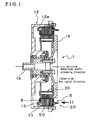
- Fig. 1 is a cross-sectional view illustrating an electric rotational motor according to an embodiment
- Fig. 2 is a partial view indicated by an arrow II in Fig. 1 ;
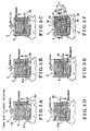
- Fig. 3A illustrates a process sequence of winding a coil around a core member of the electric rotational motor according to the embodiment
- Fig. 3B illustrates the process sequence of winding the coil around the core member of the electric rotational motor according to the embodiment
- Fig. 3C illustrates the process sequence of winding the coil around the core member of the electric rotational motor according to the embodiment
- Fig. 3D illustrates the process sequence of winding the coil around the core member of the electric rotational motor according to the embodiment
- Fig. 3F illustrates the process sequence of winding the coil around the core member of the electric rotational motor according to the embodiment
- Fig. 4 is a perspective view taken along line IV - IV in Fig. 3F ;
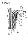
- Fig. 5 is a cross-sectional view taken along line V - V in Fig. 4 ;
- Fig. 6 is a principle diagram illustrating a winding device for manufacturing the core member
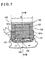
- Fig. 7 is a planar view illustrating a conventional core member
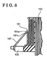
- Fig. 8 is a cross-sectional view taken along line VIII - VIII in Fig. 7 .
- Fig. 1 is a cross-sectional view illustrating an electric rotational motor (a rotational motor) 1.
- the electric rotational motor 1 will be referred to as a motor 1 hereinbelow.
- the motor 1 includes a housing 12, which is formed into a circular shape.
- a supporting member 13 is fixed at the housing 12 so as to contact an inner circumference of a cylindrical portion 12a of the housing 12.
- a plurality of core members 5 is fixed at the housing 12 so as to contact an inner circumference of the supporting member 13.
- a rotational shaft 15 is rotatably attached at a central portion of the housing 12.
- a rotor 30 is fixed at the rotational shaft 15 via a rotational plate 16.
- a right - left direction in Fig. 1 toward which the rotational shaft 15 extends, will be hereinbelow referred to as a rotational-shaft-extending direction.
- Fig. 2 is a partial view indicated by an arrow II in Fig. 1 .
- a direction, in which the motor 1 rotates, is referred to as a circumferential direction.
- a direction orthogonal to the circumferential direction is referred to as a radial direction.
- a direction to be away from a center of a rotational axis of the motor 1 is referred to as an outer side in the radial direction.
- a direction toward the center of the rotational axis of the motor 1 is referred to as an inner side in the radial direction.
- a corresponding number of core members 5 to the number of poles of the motor 1 are connected to contact each other and circularly attached at an inside of the supporting member 13, thereby forming a stator 20.
- the core members 5 respectively include magnetic cores 50 (see Fig. 1 ), which are made of a magnetic material. Each of the magnetic cores 50 is formed into a substantially T-shape in a planar view in Fig. 2 .
- the core members 5 are connected to contact each other at yoke portions 50a extending in the circumferential direction, Magnetic core portions 50b are provided at intermediate portions of the corresponding yoke portions 50a so as to extend toward the inner side in the radial direction of the motor 1.
- the plurality of core members 5 is substantially the same in structure and function. Therefore, only one of the core members 5 will be mainly described hereinbelow as an example.
- a bobbin 71 is attached to the magnetic core 50b so as to surround a circumference of the magnetic core portion 50b.
- a coil 8 is wound around the bobbin 71 so as to form a plurality of layers.
- An uppermost layer winding portion 81 of the coil 8 and a second layer winding portion 82 of the coil 8, which is provided at a lower side of an uppermost layer, are seen in Fig. 2 as an outer appearance.
- the second layer winding portion 82 is wound around the bobbin 71 for an entire length defined by the bobbin 71 in the radial direction to achieve the largest winding number.
- a winding number of the uppermost layer winding portion 81 is smaller than that of the second layer winding portion 82.
- the winding number of the second layer winding portion 82 is determined so that a clearance C relative to the adjacent core members 5 is a minimum acceptable value and so that the second layer winding portion 82 is accommodated in a trapezoid-shape shown by a double-dashed line in Fig. 2 with a minimum clearance.
- a width of the magnetic core portion 50b in the circumferential direction is fixed. However, a width of the core member 5 in the circumferential direction is larger at an outer side thereof in the radial direction than at an inner side thereof in the radial direction. Thus, an inner space of the motor 1 is maximally utilized.
- the motor 1 Similar to an operation principle of a known motor, the motor 1 outputs a rotational torque from the rotational shaft 15 by means of magnetism between the stator 20 and the rotor 30 when the coil 8 is electrified.
- Fig. 6 is a principle diagram illustrating a winding device 90 for manufacturing the core member 5.
- the winding device 90 includes a rotating station 91 and a wire-supplying station 92.
- the rotating station 91 rotates while supporting the core member 5.
- the wire-supplying station 92 supplies a wire 89a, which is integrally connected to an end portion 89 of the coil 8.
- the wire-supplying station 92 includes a wire-supplying nozzle 93.
- the wire-supplying nozzle 93 is controlled by a control device to move in X, Y and Z directions of three-dimensional directions shown in Fig. 6 .
- a rotation R of the rotating station 91 is controlled by the control device.
- Figs. 3A to 3F sequentially illustrate a completion of the uppermost layer winding portion 81 in a winding process of the coil 8 operated by the winding device 90.
- Fig. 3A illustrates that a first winding 81c of the uppermost layer winding portion 81 starts to be wound after the coil 8 is wound around the core member 5 to complete winding the second layer winding portion 82.
- the end portion 89 of the coil 8 is moved in the X direction (see Fig. 6 ) by one pitch by the wire supplying nozzle 93 so as to synchronize a rotation of the core member 5 while the core member 5 is rotated by one rotation around an axis extending in the radial direction.
- the end portion 89 is supplied with the wire 89a of a necessary length by the wire-supplying device 92 with an appropriate tension applied thereon.
- a first gap 81a (a gap), corresponding to one winding, is generated between the first winding 81c and a second winding by moving the end portion 89 by two pitches while the core member 5 is rotated by one rotation.
- a first gap 81a (a gap), corresponding to one winding, is generated between the first winding 81c and a second winding by moving the end portion 89 by two pitches while the core member 5 is rotated by one rotation.
- three windings are generated to be adjacent to each other by moving the end portion 89 by one pitch for each rotation of the core member 5.
- a second gap 81b (a gap), corresponding to one winding, is generated in a manner similar to generating the first gap 81a. Further, three windings are generated to be adjacent to each other.
- a width of the coil 8 is a predetermined width at a position shown in Fig. 3D .
- a moving direction of the end portion 89 is reversed. More specifically, the coil 8 is wound from an outer side to an inner side of the uppermost layer winding portion 81 in the radical direction before the moving direction of the coil 8 is reversed so that the coil 8 is wound from the inner side to the outer side of the uppermost layer winding portion 81 in the radial direction.
- the first gap 8 1 a is filled by the coil 8 in a manner similar to filling the second gap 81b.
- the end portion 89 is engaged with an engagement portion 6 before being cut from the wire 89a of the wire-supplying device 92.
- a manufacturing method in which the core member 5 is rotated and the end portion 89 is moved, is described above. Instead, a method may be adapted in which the core member is fixed and the end portion 89 is rotated around the core member 5 so as to revolve therearound.
- a portion connecting therebetween is a first bridge portion 85 (a bridge portion).
- a portion connecting therebetween is a second bridge portion 86 (a bridge portion).
- a portion connecting therebetween is a third bridge portion 87 (a bridge portion).
- Each of the first, second and third bridge portions 85, 86 and 87 is provided to overlap with an upper side of the uppermost layer winding portion 81 and to extend obliquely inwardly relative to the radial direction.
- Each of the first, second and third bridge portions, 85, 86 and 87 is provided at either end surface of the core member 5 in the rotational-shaft-extending direction so as not to interfere with the adjacent core members 5 and may be provided at the same side as the engagement portion 6.
- a length of each of the first, second and third bridge portions, 85, 86 and 87 is configured to be minimum.
- the coil 8 is wound with a predetermined tension in the winding process.
- the coil 8 is not held at a predetermined position and the coil 8 may be easily unwound. Further, when the motor 1 is operated, the coil 8 may be easily unwound as a result of vibration and an operational force.
- a coil may be easily unwound when a cross angle is equal to or more than 33 degree in a conventional structure and that the coil 8 is wound so as to prevent from being unwound surely and effectively when each of the first, second and third cross angles ⁇ 1, ⁇ 2 and ⁇ 3 is within a predetermined range from 9 degree to 15 degree, for example, in the above-described structure.
- two of gaps are provided.
- positions and numbers of gaps are not limited to the above-described structure and may be determined within an appropriate predetermined angle range.
- Fig. 4 is a perspective view illustrating a cross-sectional surface taken along line IV - IV in Fig. 3F .
- Fig. 5 is an end view taken along line V - V in Fig. 4 .
- the third bridge portion 87 which is one terminal of the coil 8, and a conductor portion 88, which is led from a lowermost layer winding portion 83 of the coil 8 and is the other terminal of the coil 8, are engaged with the engagement portion 6.
- the third bridge portion 87 and the conductor portion 88 are connected to a first power source terminal 18 and a second power source terminal 19, respectively.
- the magnetic core 50 is configured by stacking a plurality of magnetic steel plates 52.
- the coil 8 is wound around the magnetic core portion 50b via the bobbin 71, which surrounds a circumference of the magnetic core 50. Every cross section of the magnetic core portion 50b, extending orthogonally relative to the radial direction, is formed into a substantially rectangular shape and formed to be a fixed shape in the radial direction.
- the magnetic core portion 50b and the yoke portion 50a are respectively formed into shapes in which the magnetic core 50 is configured by stacking the same-shaped magnetic steel plates 52 in layers. Therefore, the magnetic steel plates 52 may be manufactured by the same pressing die at a low cost. Further, an additional component is not required.
- the first winding 81c of the uppermost layer winding portion 81 is wound to contact a holding wall 71a of the bobbin 71.
- a winding position of a final winding 81d, which leads the third bridge portion 87, is surely maintained by contact of the final winding 81d with the first winding 81c. Therefore, a tension applied on the third bridge portion 87 is prevented from being loosened and thereby improving an unwinding prevention effect.
- the third bridge portion 87 is led by the final winding 81d, which is positioned in the vicinity of the engagement portion 6. Therefore, the third bridge portion 87 extends in a short length. Accordingly, it is prevented that operators or tools contact the third bridge portion 87 in a motor-assembly operation and thereby preventing unwinding.
- a rotational motor (1) includes a stator (20) formed by a core member (5) including: a magnetic core portion (50b) extending in a radial direction of the rotational motor (1) and formed into a fixed shape in every cross section thereof extending orthogonally relative to the radial direction, a coil (8) wound around the magnetic core portion (50b) to form a plurality of layers and an engagement member (6) engaging the coil (8).
- a gap (81a, 81b) is generated between windings of the coil (8) at a predetermined position when an uppermost layer winding portion (81) of the coil (8) is wound in series with a second layer winding portion (82) from an outer side to an inner side of the uppermost layer winding portion (81) in a radial direction.
- the coil (8) is wound to fill the gap (81a, 81b) when a winding position of the coil (8) is returned from an innermost side to the outer side of the uppermost layer winding portion (81) in the radial direction.
Landscapes
- Engineering & Computer Science (AREA)
- Power Engineering (AREA)
- Manufacturing & Machinery (AREA)
- Manufacture Of Motors, Generators (AREA)
- Windings For Motors And Generators (AREA)
- Iron Core Of Rotating Electric Machines (AREA)
- Insulation, Fastening Of Motor, Generator Windings (AREA)
Abstract
Description
- The present invention relates to an electric rotational motor having a core member configured by winding a coil around a magnetic core portion, more specifically the present invention relates to a rotational motor having a core member including a coil wound so as not to be easily unwound.
- A rotational motor is known having a stator, which configures a plurality of poles by assembling a plurality of core members so as to form a substantially circular. shape.
- In the above-described rotational motor, a width of the core member in a circumferential direction of the rotational motor is determined to be shorter at an outer side of the core member than at an inner side thereof in a radial direction of the rotational motor (in a radial direction of the circular-shaped stator) when seen from a rotational-shaft-extending direction. In other words, the core member is formed to be accommodated, with a minimum clearance, into a substantially trapezoid shape, whose width at an outer side thereof in the radial direction forms a longer side and whose width at an inner side thereof in the radial direction forms a shorter side being shorter than the longer side thereof. Consequently, the rotational motor is configured to be downsized and to output a high torque by minimizing a clearance generated between the adjacent core members.
- A method for accommodating core members into a substantially trapezoid-shape with a minimum clearance is disclosed in
JP2007-215364A Figs. 1 to 3 in reference 1, for example). - Further, a method for having a minimum clearance relative to a predetermined substantially trapezoid-shape is disclosed in reference 1. According to reference 1, a magnetic core portion, extending in the radial direction of the motor, is formed into a substantially fixed shape in every cross section thereof extending orthogonally relative to the magnetic-core-extending direction, so as to maintain a magnetic flux density. A coil is wound to a greater extent around an outer portion of the magnetic core portion than around an inner portion thereof in the radial direction (see
Fig. 7 in reference 1, for example). - A method is disclosed in reference 1 by which the three-dimensional magnetic core portion, shown in
Figs. 1 to 3 of reference 1 and having variation in width and thickness thereof, is formed from a pressed powder material. However, the magnetic core portion made of the pressed powder material does not have a sufficient strength. Further, a method for forming the three-dimensional shape is disclosed in reference I. An additional component is provided to the magnetic core portion, which is formed into the fixed shape in every cross section thereof and which is configured by stacking a plurality of magnetic steel plates conventionally adapted to a usual motor in layers. However, in such case, a manufacturing cost increases because the additional component is required. - On the other hand, the method for having the minimum clearance relative to the predetermined substantially trapezoid-shape is known in which the coil is wound around the magnetic core portion, which is formed into the fixed shape in every cross section thereof in the magnetic-core-portion-extending direction, so as to form a substantially trapezoid-shape. However, in such case, the wound coil is easily unwound. Specifically when a difference between a longer side and a shorter side of a trapezoid-shape is smaller relative to the core member disclosed in
Fig. 7 in reference 1, in other words, in an electric rotational motor having a stator of a more number of poles, a wound coil is easily unwound. - An example of a case where a difference in width between a longer side A and a shorter side B of a trapezoid-shape is small is shown in
Figs. 7 and8 . In the example, acore member 105 is manufactured by a conventional winding method. Thecore member 105 is configured by winding acoil 108 around amagnetic core portion 150, which extends to be a fixed shape in every cross section thereof. Thecoil 108 is wound around themagnetic core portion 150 to form a plurality of layers. A winding number of an uppermostlayer winding portion 181 is smaller than that of a secondlayer winding portion 182, which is provided at a lower side of the uppermost layer,windingportion 181. ("Upper" and "lower" hereinbelow corresponds to a left side and a right side inFig. 8 , respectively.) Consequently, thecore member 105 is accommodated in the trapezoid-shape shown by a double-dashed line inFig. 7 with a minimum clearance. - A winding number of the uppermost
layer winding portion 181 of thecore member 105 increases when the difference in width between the longer side A and the shorter side B is small compared to when the difference in width between the longer side A and the shorter side B is large. Therefore, a length between afinal winding portion 181a of the uppermostlayer winding portion 181 of thecoil 108 and anengagement portion 106 increases. Further, a cross angle α between abridge portion 187, connecting thefinal winding portion 181a and theengagement portion 106, and awinding portion 181b, wound before thefinal winding portion 181a, increases. - When the cross angle α is equal to or larger than a predetermined value, the final winding
portion 181a crosses over the windingportion 181b to be displaced from a predetermined position during a coil-winding process or a motor-assembling process. Further, as illustrated inFig. 7 , thebridge portion 187 is connected to theengagement portion 106, engaging with anend portion 189 of thecoil 108, so as to extend obliquely. Therefore, operators and tools easily contact thebridge portion 187 during the motor-assembly process and the coil is easily unwound. - A need thus exits for an electric rotational motor having a core member, which is manufactured at a low cost in a method where a coil is wound therearound so as not to be easily unwound.
- According to an aspect of the present invention, a rotational motor includes a stator formed by a core member including: a magnetic core portion, extending in a radial direction of the rotational motor and formed into a fixed shape in every cross section thereof extending orthogonally relative to the radial direction; coil, wound around the magnetic core portion to form a plurality of layers and having a less winding number thereof at an uppermost layer winding portion of the plurality of layers than a winding number at a second layer winding portion provided at a lower side of the uppermost layer winding portion; and an engagement member, provided at an outer side of the magnetic core portion in the radial direction and engaging with an end portion of the coil. A gap is generated between windings of the coil at a predetermined position when the uppermost layer winding portion of the coil is wound in series with the second layer winding portion from an outer side to an inner side of the uppermost layer winding portion in the radial direction. The coil is wound to fill the gap when a winding position of the coil is returned from an innermost side to the outer side of the uppermost layer winding portion in the radial direction.
- Accordingly, the cross angle between the coil and the bridge portion is decreased by winding the coil to fill the gap, provided at an intermediate portion of the uppermost layer winding portion, when the coil is wound from the inner side of the uppermost layer winding portion to the outer side thereof in the radial direction. Consequently, the coil is prevented from being easily unwound.
- According to a further aspect of the present invention, one or more of the gap is provided at the uppermost layer winding portion, and a portion of the coil, wound from the innermost side to the outer side of the uppermost layer winding portion in the radial direction and overlapping with the uppermost layer winding portion, forms a bridge portion. The bridge portion, engaged with the engagement portion, is provided at an end surface of the magnetic core portion at either side in a rotational-shaft-extending direction where the engagement portion is provided.
- Accordingly, a length of the bridge portion is minimized. Therefore, it is prevented that operators and tools contact the bridge portion in a motor-assembly operation and thereby preventing unwinding.
- According to a further aspect of the present invention, the predetermined position of the gap is determined so that a cross angle between the bridge portion and the coil of the uppermost layer winding portion is within a predetermined angle range.
- Accordingly, unwinding is surely prevented by determining the cross angle between the coil and the bridge portion to be within the predetermined range.
- According to a further aspect of the present invention, at least one winding of the coil is wound between the engagement portion and the gap, provided to be the closest to the engagement portion, when the coil of the uppermost layer winding portion is wound in series with the second layer winding portion from the outer side to the inner side of the uppermost layer winding portion in the radial direction.
- Accordingly, the winding position of a final winding, which leads the bridge portion, is surely maintained by contact of the final winding with the first winding. Therefore, a tension applied on the bridge portion is prevented from being loosened and thereby improving an unwinding prevention effect.
- According to a further aspect of the present invention, the coil is wound around the core member in a manner in which one of the core member and the end portion of the coil is rotated and the other one of the core member and the end portion of the coil is moved synchronously with the rotation in a direction in which the magnetic core portion extends by controlling a speed.
- Accordingly, the coil is wound around the core member so as not to be easily unwound.
- According to a further aspect of the present invention, the bridge portion overlaps with the uppermost layer winding portion and extends obliquely inwardly relative to the radial direction.
- According to a further aspect of the present invention, the cross angle is within a range from 9 degree to 15 degree.
- According to a further aspect of the present invention, a bobbin is attached to the magnetic core portion so as to surround a circumference of the magnetic core portion. A first winding of the uppermost layer winding portion is wound to contact a holding wall formed at the bobbin, and a final winding, led by the bridge portion, contacts the first winding.
- The foregoing and additional features and characteristics of the present invention will become more apparent from the following detailed description considered with the reference to the accompanying drawings, wherein:
-
Fig. 1 is a cross-sectional view illustrating an electric rotational motor according to an embodiment; -
Fig. 2 is a partial view indicated by an arrow II inFig. 1 ; -
Fig. 3A illustrates a process sequence of winding a coil around a core member of the electric rotational motor according to the embodiment; -
Fig. 3B illustrates the process sequence of winding the coil around the core member of the electric rotational motor according to the embodiment; -
Fig. 3C illustrates the process sequence of winding the coil around the core member of the electric rotational motor according to the embodiment; -
Fig. 3D illustrates the process sequence of winding the coil around the core member of the electric rotational motor according to the embodiment; -
Fig. 3F illustrates the process sequence of winding the coil around the core member of the electric rotational motor according to the embodiment; -
Fig. 4 is a perspective view taken along line IV - IV inFig. 3F ; -
Fig. 5 is a cross-sectional view taken along line V - V inFig. 4 ; -
Fig. 6 is a principle diagram illustrating a winding device for manufacturing the core member; -
Fig. 7 is a planar view illustrating a conventional core member; and -
Fig. 8 is a cross-sectional view taken along line VIII - VIII inFig. 7 . - A detailed description of an embodiment will be described hereinbelow with reference to the attached drawings.
-
Fig. 1 is a cross-sectional view illustrating an electric rotational motor (a rotational motor) 1. The electric rotational motor 1 will be referred to as a motor 1 hereinbelow. - The motor 1 includes a
housing 12, which is formed into a circular shape. A supportingmember 13 is fixed at thehousing 12 so as to contact an inner circumference of acylindrical portion 12a of thehousing 12. A plurality ofcore members 5 is fixed at thehousing 12 so as to contact an inner circumference of the supportingmember 13. - A
rotational shaft 15 is rotatably attached at a central portion of thehousing 12. Arotor 30 is fixed at therotational shaft 15 via arotational plate 16. A right - left direction inFig. 1 , toward which therotational shaft 15 extends, will be hereinbelow referred to as a rotational-shaft-extending direction. -
Fig. 2 is a partial view indicated by an arrow II inFig. 1 . A direction, in which the motor 1 rotates, is referred to as a circumferential direction. A direction orthogonal to the circumferential direction is referred to as a radial direction. A direction to be away from a center of a rotational axis of the motor 1 is referred to as an outer side in the radial direction. A direction toward the center of the rotational axis of the motor 1 is referred to as an inner side in the radial direction. - A corresponding number of
core members 5 to the number of poles of the motor 1 are connected to contact each other and circularly attached at an inside of the supportingmember 13, thereby forming astator 20. Thecore members 5 respectively include magnetic cores 50 (seeFig. 1 ), which are made of a magnetic material. Each of themagnetic cores 50 is formed into a substantially T-shape in a planar view inFig. 2 . Thecore members 5 are connected to contact each other atyoke portions 50a extending in the circumferential direction,Magnetic core portions 50b are provided at intermediate portions of thecorresponding yoke portions 50a so as to extend toward the inner side in the radial direction of the motor 1. The plurality ofcore members 5 is substantially the same in structure and function. Therefore, only one of thecore members 5 will be mainly described hereinbelow as an example. - A
bobbin 71 is attached to themagnetic core 50b so as to surround a circumference of themagnetic core portion 50b. Acoil 8 is wound around thebobbin 71 so as to form a plurality of layers. An uppermostlayer winding portion 81 of thecoil 8 and a secondlayer winding portion 82 of thecoil 8, which is provided at a lower side of an uppermost layer, are seen inFig. 2 as an outer appearance. ("Upper" and "lower" hereinbelow corresponds to a right side and a left side inFig. 1 .) - The second
layer winding portion 82 is wound around thebobbin 71 for an entire length defined by thebobbin 71 in the radial direction to achieve the largest winding number. On the other hand, a winding number of the uppermostlayer winding portion 81 is smaller than that of the secondlayer winding portion 82. The winding number of the secondlayer winding portion 82 is determined so that a clearance C relative to theadjacent core members 5 is a minimum acceptable value and so that the secondlayer winding portion 82 is accommodated in a trapezoid-shape shown by a double-dashed line inFig. 2 with a minimum clearance. A width of themagnetic core portion 50b in the circumferential direction is fixed. However, a width of thecore member 5 in the circumferential direction is larger at an outer side thereof in the radial direction than at an inner side thereof in the radial direction. Thus, an inner space of the motor 1 is maximally utilized. - Similar to an operation principle of a known motor, the motor 1 outputs a rotational torque from the
rotational shaft 15 by means of magnetism between thestator 20 and therotor 30 when thecoil 8 is electrified. - A structure and a manufacturing method of the
coil 8 of thecore member 5 according to the embodiment will be described hereinbelow. -
Fig. 6 is a principle diagram illustrating a windingdevice 90 for manufacturing thecore member 5. The windingdevice 90 includes arotating station 91 and a wire-supplyingstation 92. The rotatingstation 91 rotates while supporting thecore member 5. The wire-supplyingstation 92 supplies awire 89a, which is integrally connected to anend portion 89 of thecoil 8. The wire-supplyingstation 92 includes a wire-supplyingnozzle 93. The wire-supplyingnozzle 93 is controlled by a control device to move in X, Y and Z directions of three-dimensional directions shown inFig. 6 . A rotation R of therotating station 91 is controlled by the control device. -
Figs. 3A to 3F sequentially illustrate a completion of the uppermostlayer winding portion 81 in a winding process of thecoil 8 operated by the windingdevice 90. -
Fig. 3A illustrates that a first winding 81c of the uppermostlayer winding portion 81 starts to be wound after thecoil 8 is wound around thecore member 5 to complete winding the secondlayer winding portion 82. In order to wind thecoil 8 around thecore member 5, theend portion 89 of thecoil 8 is moved in the X direction (seeFig. 6 ) by one pitch by thewire supplying nozzle 93 so as to synchronize a rotation of thecore member 5 while thecore member 5 is rotated by one rotation around an axis extending in the radial direction. Theend portion 89 is supplied with thewire 89a of a necessary length by the wire-supplyingdevice 92 with an appropriate tension applied thereon. - As illustrated in
Fig. 3B , afirst gap 81a (a gap), corresponding to one winding, is generated between the first winding 81c and a second winding by moving theend portion 89 by two pitches while thecore member 5 is rotated by one rotation. As illustrated inFig. 3C , after thefirst gap 81a is generated, three windings are generated to be adjacent to each other by moving theend portion 89 by one pitch for each rotation of thecore member 5. - As illustrated in
Fig. 3D , asecond gap 81b (a gap), corresponding to one winding, is generated in a manner similar to generating thefirst gap 81a. Further, three windings are generated to be adjacent to each other. A width of thecoil 8 is a predetermined width at a position shown inFig. 3D . Then, a moving direction of theend portion 89 is reversed. More specifically, thecoil 8 is wound from an outer side to an inner side of the uppermostlayer winding portion 81 in the radical direction before the moving direction of thecoil 8 is reversed so that thecoil 8 is wound from the inner side to the outer side of the uppermostlayer winding portion 81 in the radial direction. - After the moving direction of the
end portion 89 is reversed, a position of theend portion 89 is returned by a necessary number of pitches so that thesecond gap 81b, to which thecoil 8 is positioned to be the closest, is filled with thecoil 8 while thecore portion 5 is rotated by one rotation, thereby winding theend portion 89, as illustrated inFig. 3E . - As illustrated in
Fig. 3F , thefirst gap 8 1 a is filled by thecoil 8 in a manner similar to filling thesecond gap 81b. In the final winding process, theend portion 89 is engaged with anengagement portion 6 before being cut from thewire 89a of the wire-supplyingdevice 92. - A manufacturing method, in which the
core member 5 is rotated and theend portion 89 is moved, is described above. Instead, a method may be adapted in which the core member is fixed and theend portion 89 is rotated around thecore member 5 so as to revolve therearound. - As illustrated in
Fig. 3F , when a winding position of thecoil 8 is returned from an inner end of the uppermostlayer winding portion 81 in the radial direction to thesecond gap 81b, a portion connecting therebetween is a first bridge portion 85 (a bridge portion). Likewise, as illustrated inFig. 3F , when a winding position of thecoil 8 is returned from thesecond gap 81b to thefirst gap 81a, a portion connecting therebetween is a second bridge portion 86 (a bridge portion). Likewise, as illustrated inFig. 3F , when a winding position of thecoil 8 is returned from thefirst gap 81a to theengagement portion 6, a portion connecting therebetween is a third bridge portion 87 (a bridge portion). Each of the first, second andthird bridge portions layer winding portion 81 and to extend obliquely inwardly relative to the radial direction. Each of the first, second and third bridge portions, 85, 86 and 87 is provided at either end surface of thecore member 5 in the rotational-shaft-extending direction so as not to interfere with theadjacent core members 5 and may be provided at the same side as theengagement portion 6. A length of each of the first, second and third bridge portions, 85, 86 and 87 is configured to be minimum. - As illustrated in
Fig. 3F , each of the first, second andthird bridge portions coil 8, wound around the uppermostlayer winding portion 81, form a first cross angle α1 (a cross angle), a second cross angle α2 (a cross angle) and a third cross angle α3 (a cross angle), respectively. Thecoil 8 is wound with a predetermined tension in the winding process. When each of the first, second and third cross angles α1, α2 and α3 is equal to or more than a predetermined value, thecoil 8 is not held at a predetermined position and thecoil 8 may be easily unwound. Further, when the motor 1 is operated, thecoil 8 may be easily unwound as a result of vibration and an operational force. Experiments show that a coil may be easily unwound when a cross angle is equal to or more than 33 degree in a conventional structure and that thecoil 8 is wound so as to prevent from being unwound surely and effectively when each of the first, second and third cross angles α1, α2 and α3 is within a predetermined range from 9 degree to 15 degree, for example, in the above-described structure. According to the above-described embodiment, two of gaps, the first andsecond gaps -
Fig. 4 is a perspective view illustrating a cross-sectional surface taken along line IV - IV inFig. 3F .Fig. 5 is an end view taken along line V - V inFig. 4 . - The
third bridge portion 87, which is one terminal of thecoil 8, and aconductor portion 88, which is led from a lowermostlayer winding portion 83 of thecoil 8 and is the other terminal of thecoil 8, are engaged with theengagement portion 6. After thecore member 5 is assembled to the motor 1, thethird bridge portion 87 and theconductor portion 88 are connected to a firstpower source terminal 18 and a secondpower source terminal 19, respectively. - As illustrated in
Fig. 4 , themagnetic core 50 is configured by stacking a plurality ofmagnetic steel plates 52. Thecoil 8 is wound around themagnetic core portion 50b via thebobbin 71, which surrounds a circumference of themagnetic core 50. Every cross section of themagnetic core portion 50b, extending orthogonally relative to the radial direction, is formed into a substantially rectangular shape and formed to be a fixed shape in the radial direction. Themagnetic core portion 50b and theyoke portion 50a are respectively formed into shapes in which themagnetic core 50 is configured by stacking the same-shapedmagnetic steel plates 52 in layers. Therefore, themagnetic steel plates 52 may be manufactured by the same pressing die at a low cost. Further, an additional component is not required. - As illustrated in
Fig. 5 , the first winding 81c of the uppermostlayer winding portion 81 is wound to contact a holdingwall 71a of thebobbin 71. A winding position of a final winding 81d, which leads thethird bridge portion 87, is surely maintained by contact of the final winding 81d with the first winding 81c. Therefore, a tension applied on thethird bridge portion 87 is prevented from being loosened and thereby improving an unwinding prevention effect. Further, thethird bridge portion 87 is led by the final winding 81d, which is positioned in the vicinity of theengagement portion 6. Therefore, thethird bridge portion 87 extends in a short length. Accordingly, it is prevented that operators or tools contact thethird bridge portion 87 in a motor-assembly operation and thereby preventing unwinding. - In the above-described embodiment, a cross section of a wire material of the
coil 8 is described as a circular-shaped cross section. However, a core member may be adapted instead which includes a wire material having a different cross section, such as a substantially rectangular-shaped cross section, or the like.
A rotational motor (1) includes a stator (20) formed by a core member (5) including: a magnetic core portion (50b) extending in a radial direction of the rotational motor (1) and formed into a fixed shape in every cross section thereof extending orthogonally relative to the radial direction, a coil (8) wound around the magnetic core portion (50b) to form a plurality of layers and an engagement member (6) engaging the coil (8). A gap (81a, 81b) is generated between windings of the coil (8) at a predetermined position when an uppermost layer winding portion (81) of the coil (8) is wound in series with a second layer winding portion (82) from an outer side to an inner side of the uppermost layer winding portion (81) in a radial direction. The coil (8) is wound to fill the gap (81a, 81b) when a winding position of the coil (8) is returned from an innermost side to the outer side of the uppermost layer winding portion (81) in the radial direction.
Claims (8)
- A rotational motor (1) comprising:A stator (20) formed by a core member (5) including
a magnetic core portion (50b) extending in a radial direction of the rotational motor (1) and formed into a fixed shape in every cross section thereof extending orthogonally relative to the radial direction,
a coil (8) wound around the magnetic core portion (50b) to form a plurality of layers and having a less winding number thereof at an uppermost layer winding portion (81) of the plurality of layers than a winding number at a second layer winding portion (82) provided at a lower side of the uppermost layer winding portion (81), and
an engagement member (6) provided at an outer side of the magnetic core portion (50b) in the radial direction and engaging with an end portion (89) of the coil (8), wherein
a gap (81a, 81b) is generated between windings of the coil (8) at a predetermined position when the uppermost layer winding portion (81) of the coil (8) is wound in series with the second layer winding portion (82) from an outer side to an inner side of the uppermost layer winding portion (81) in the radial direction, and wherein
the coil (8) is wound to fill the gap (81a, 81b) when a winding position of the coil (8) is returned from an innermost side to the outer side of the uppermost layer winding portion (81) in the radial direction. - The rotational motor (1) according to claim 1, wherein
one or more of the gap (81a, 81b) is provided at the uppermost layer winding portion (81), and
a portion of the coil (8) wound from the innermost side to the outer side of the uppermost layer winding portion (81) in the radial direction and overlapping with the
uppermost layer winding portion (81) forms a bridge portion (85, 86, 87),
the bridge portion (85,86, 87) being engaged with the engagement portion (6) and provided at an end surface of the magnetic core portion (50b) at either side in a rotational-shaft-extending direction where the engagement portion (6) is provided. - The rotational motor (1) according to claim 2, wherein
the predetermined position of the gap (81a, 81b) is determined so that a cross angle (α1, α2, α3) between the bridge portion (85, 86, 87) and the coil (8) of the uppermost layer winding portion (81) is within a predetermined angle range. - The rotational motor (1) according to any one of claims 1 to 3, wherein
at least one winding of the coil (8) is wound between the engagement portion (6) and the gap (81a, 81b), provided to be the closest to the engagement portion (6), when the coil (8) of the uppermost layer winding portion (81) is wound in series with the second layer winding portion (82) from the outer side to the inner side of the uppermost layer winding portion (81) in the radial direction. - A method for manufacturing the rotational motor (1) according to claim 1, wherein
the coil (8) is wound around the core member (5) in a manner in which one of the core member (5) and the end portion (89) of the coil (8) is rotated and the other one of the core member (5) and the end portion (89) of the coil (8) is moved synchronously with the rotation in a direction in which the magnetic core portion (50b) extends by controlling a speed. - The rotational motor (1) according to either claim 2 or 3, wherein
the bridge portion (85, 86, 87) overlaps with the uppermost layer winding portion (81) and extends obliquely inwardly relative to the radial direction. - The rotational motor (1) according to claim 3, wherein
the cross angle (α1, α2, α3) is within a range from 9 degree to 15 degree. - The rotational motor (1) according to any one of claims 2, 3, 6 and 7, wherein
a bobbin (71) is attached to the magnetic core portion (50b) so as to surround a circumference of the magnetic core portion (50b),
a first winding (81c) of the uppermost layer winding portion (81) is wound to contact a holding wall (71a) formed at the bobbin (71), and
a final winding (81d), led by the bridge portion (85, 86, 87), contacts the first winding (81c).
Applications Claiming Priority (1)
| Application Number | Priority Date | Filing Date | Title |
|---|---|---|---|
| JP2008080232A JP5315743B2 (en) | 2008-03-26 | 2008-03-26 | Electric rotary motor |
Publications (2)
| Publication Number | Publication Date |
|---|---|
| EP2106012A2 true EP2106012A2 (en) | 2009-09-30 |
| EP2106012A3 EP2106012A3 (en) | 2017-02-15 |
Family
ID=40848684
Family Applications (1)
| Application Number | Title | Priority Date | Filing Date |
|---|---|---|---|
| EP09155326.3A Withdrawn EP2106012A3 (en) | 2008-03-26 | 2009-03-17 | Electric rotational motor |
Country Status (3)
| Country | Link |
|---|---|
| US (1) | US8058766B2 (en) |
| EP (1) | EP2106012A3 (en) |
| JP (1) | JP5315743B2 (en) |
Cited By (2)
| Publication number | Priority date | Publication date | Assignee | Title |
|---|---|---|---|---|
| WO2016000882A1 (en) * | 2014-07-04 | 2016-01-07 | Zf Friedrichshafen Ag | Coil for an electric machine |
| CN112362212A (en) * | 2020-11-12 | 2021-02-12 | 常州路航轨道装备有限公司 | Pantograph static tension detector and pantograph static tension detection control method |
Families Citing this family (14)
| Publication number | Priority date | Publication date | Assignee | Title |
|---|---|---|---|---|
| AT505066B1 (en) * | 2007-03-16 | 2008-12-15 | Egston System Electronics Egge | METHOD FOR MACHINING WRAP OF A COIL |
| JP5292542B2 (en) * | 2009-02-05 | 2013-09-18 | 多摩川精機株式会社 | Resolver stator structure |
| KR101074939B1 (en) * | 2009-11-23 | 2011-10-18 | 뉴모텍(주) | Magmate Winding Frame and Stator Core with the Same |
| JP5636710B2 (en) * | 2010-03-23 | 2014-12-10 | 日産自動車株式会社 | Insulator for rotating electrical machine and method for manufacturing stator winding structure |
| US8310115B2 (en) * | 2010-07-23 | 2012-11-13 | General Electric Company | High power-density, high efficiency, non-permanent magnet electric machine |
| JPWO2012127658A1 (en) * | 2011-03-23 | 2014-07-24 | 三菱電機株式会社 | Core winding method and stator |
| GB2495544B (en) * | 2011-10-14 | 2014-11-05 | Dyson Technology Ltd | Stator for an electrical machine |
| CN204633497U (en) * | 2012-09-28 | 2015-09-09 | 株式会社安川电机 | Coil, rotary and linear motors |
| JP6026259B2 (en) * | 2012-12-13 | 2016-11-16 | 愛三工業株式会社 | Stator and electric pump |
| US10050482B2 (en) | 2013-10-30 | 2018-08-14 | Mitsubishi Electric Corporation | Electric motor, compressor including the same, and method of manufacturing electric motor |
| WO2017072912A1 (en) | 2015-10-29 | 2017-05-04 | 三菱電機株式会社 | Rotating electric machine |
| ES2622300B1 (en) * | 2016-03-15 | 2018-01-09 | Benet SAFONT MARESMA | Axial electric motor. |
| JP6790761B2 (en) * | 2016-11-24 | 2020-11-25 | アイシン精機株式会社 | Manufacturing method of rotary electric machine |
| CN112910186A (en) * | 2019-12-04 | 2021-06-04 | 北京金风科创风电设备有限公司 | Installation method of split motor |
Citations (1)
| Publication number | Priority date | Publication date | Assignee | Title |
|---|---|---|---|---|
| JP2007215364A (en) | 2006-02-10 | 2007-08-23 | Sumitomo Electric Ind Ltd | Motor core parts and motor parts |
Family Cites Families (16)
| Publication number | Priority date | Publication date | Assignee | Title |
|---|---|---|---|---|
| US2647696A (en) * | 1948-11-23 | 1953-08-04 | Styled Cie Electro Mecanique S | Stator winding machine |
| JPH0775270A (en) * | 1993-09-03 | 1995-03-17 | Canon Electron Inc | Rotating magnetic field generating unit for electromagnetic rotary apparatus |
| US6255756B1 (en) * | 1997-12-01 | 2001-07-03 | General Electric Company | Winding arrangement for switched reluctance machine based internal starter generator |
| JP3498129B2 (en) * | 2001-05-24 | 2004-02-16 | 三菱電機株式会社 | Rotating electric machine |
| US6851175B2 (en) * | 2001-09-12 | 2005-02-08 | Delphi Technologies, Inc. | Wound stator core and method of making |
| JP3980402B2 (en) * | 2002-05-13 | 2007-09-26 | 本田技研工業株式会社 | Rotating electric machine |
| JP3903922B2 (en) * | 2003-01-27 | 2007-04-11 | 株式会社デンソー | Concentrated winding stator coil of rotating electric machine |
| US7026739B2 (en) * | 2003-05-23 | 2006-04-11 | Honda Motor Co., Ltd | Stator and insulating bobbin and a manufacturing method of the stator |
| JP2005012876A (en) * | 2003-06-17 | 2005-01-13 | Mitsubishi Electric Corp | Winding structure of motor stator core |
| JP2005057931A (en) * | 2003-08-06 | 2005-03-03 | Honda Motor Co Ltd | Stator |
| JP4490177B2 (en) * | 2003-08-26 | 2010-06-23 | 本田技研工業株式会社 | Stator winding and method for manufacturing stator winding |
| JP4784440B2 (en) * | 2006-08-11 | 2011-10-05 | アイシン精機株式会社 | Winding device |
| JP2008136284A (en) | 2006-11-28 | 2008-06-12 | Aisin Seiki Co Ltd | Varnish impregnation equipment |
| AT505066B1 (en) * | 2007-03-16 | 2008-12-15 | Egston System Electronics Egge | METHOD FOR MACHINING WRAP OF A COIL |
| JP5061735B2 (en) * | 2007-06-06 | 2012-10-31 | 日産自動車株式会社 | Stator winding unwinding prevention structure and stator manufacturing method having unwinding prevention structure |
| JP5469873B2 (en) * | 2008-03-11 | 2014-04-16 | 株式会社日立製作所 | Rotating electric machine |
-
2008
- 2008-03-26 JP JP2008080232A patent/JP5315743B2/en not_active Expired - Fee Related
-
2009
- 2009-03-17 EP EP09155326.3A patent/EP2106012A3/en not_active Withdrawn
- 2009-03-20 US US12/408,477 patent/US8058766B2/en not_active Expired - Fee Related
Patent Citations (1)
| Publication number | Priority date | Publication date | Assignee | Title |
|---|---|---|---|---|
| JP2007215364A (en) | 2006-02-10 | 2007-08-23 | Sumitomo Electric Ind Ltd | Motor core parts and motor parts |
Cited By (3)
| Publication number | Priority date | Publication date | Assignee | Title |
|---|---|---|---|---|
| WO2016000882A1 (en) * | 2014-07-04 | 2016-01-07 | Zf Friedrichshafen Ag | Coil for an electric machine |
| CN112362212A (en) * | 2020-11-12 | 2021-02-12 | 常州路航轨道装备有限公司 | Pantograph static tension detector and pantograph static tension detection control method |
| CN112362212B (en) * | 2020-11-12 | 2022-05-06 | 常州路航轨道装备有限公司 | Pantograph static tension detector and pantograph static tension detection control method |
Also Published As
| Publication number | Publication date |
|---|---|
| US20090243420A1 (en) | 2009-10-01 |
| JP5315743B2 (en) | 2013-10-16 |
| JP2009240010A (en) | 2009-10-15 |
| EP2106012A3 (en) | 2017-02-15 |
| US8058766B2 (en) | 2011-11-15 |
Similar Documents
| Publication | Publication Date | Title |
|---|---|---|
| US8058766B2 (en) | Electric rotational motor | |
| US12470114B2 (en) | Apparatus for inserting an undulated coil assembly in slots of a core of a stator of a dynamoelectric machine | |
| US10910928B2 (en) | Stator assembly method and stator assembly apparatus | |
| KR100923463B1 (en) | Dynamoelectric machine stator and method for mounting prewound coils thereunto | |
| US10594182B2 (en) | Stator manufacturing method and stator | |
| CN103107659B (en) | The winding structure of lenticular wire | |
| JP5105169B2 (en) | Resolver, motor, power steering device, and resolver manufacturing method | |
| EP2680412B1 (en) | Arrangement of coil wires in a rotor of an electric motor | |
| WO2007055210A1 (en) | Motor core part and motor part | |
| WO2013190673A1 (en) | Rotary electric machine | |
| CN103840576A (en) | Wire guide for use in an electric machine | |
| CN108141082A (en) | Electric rotating machine | |
| JP2002272045A (en) | Stator structure of rotating magnetic field electric apparatus | |
| JP2014023299A5 (en) | ||
| JP6196804B2 (en) | Rotating electric machine stator | |
| JP5768305B1 (en) | Stator manufacturing method and apparatus | |
| JP6789062B2 (en) | Manufacturing method of stator and stator winding of rotary electric machine | |
| JP2007244115A (en) | Winding structure of motor, winding method thereof and winding device thereof | |
| JP2014230293A (en) | Manufacturing method of stator for rotary electric machine | |
| JP2008172863A (en) | Rotating electric machine and manufacturing method thereof | |
| US20230246528A1 (en) | Method for producing a skewed stator | |
| JP2023140069A (en) | Coil manufacturing method, coil, and electric motor | |
| JP2005229678A (en) | Motor and coil winder for motor core | |
| JP6824014B2 (en) | Winding device | |
| JP2024044240A (en) | Stator, rotating electric machine, and stator winding method |
Legal Events
| Date | Code | Title | Description |
|---|---|---|---|
| PUAI | Public reference made under article 153(3) epc to a published international application that has entered the european phase |
Free format text: ORIGINAL CODE: 0009012 |
|
| AK | Designated contracting states |
Kind code of ref document: A2 Designated state(s): AT BE BG CH CY CZ DE DK EE ES FI FR GB GR HR HU IE IS IT LI LT LU LV MC MK MT NL NO PL PT RO SE SI SK TR |
|
| AX | Request for extension of the european patent |
Extension state: AL BA RS |
|
| PUAL | Search report despatched |
Free format text: ORIGINAL CODE: 0009013 |
|
| AK | Designated contracting states |
Kind code of ref document: A3 Designated state(s): AT BE BG CH CY CZ DE DK EE ES FI FR GB GR HR HU IE IS IT LI LT LU LV MC MK MT NL NO PL PT RO SE SI SK TR |
|
| AX | Request for extension of the european patent |
Extension state: AL BA RS |
|
| RIC1 | Information provided on ipc code assigned before grant |
Ipc: H02K 15/095 20060101ALI20170111BHEP Ipc: H02K 3/52 20060101AFI20170111BHEP Ipc: H02K 1/14 20060101ALI20170111BHEP |
|
| 17P | Request for examination filed |
Effective date: 20170810 |
|
| RBV | Designated contracting states (corrected) |
Designated state(s): AT BE BG CH CY CZ DE DK EE ES FI FR GB GR HR HU IE IS IT LI LT LU LV MC MK MT NL NO PL PT RO SE SI SK TR |
|
| AKX | Designation fees paid |
Designated state(s): AT BE BG CH CY CZ DE DK EE ES FI FR GB GR HR HU IE IS IT LI LT LU LV MC MK MT NL NO PL PT RO SE SI SK TR |
|
| AXX | Extension fees paid |
Extension state: RS Extension state: AL Extension state: BA |
|
| 17Q | First examination report despatched |
Effective date: 20180226 |
|
| STAA | Information on the status of an ep patent application or granted ep patent |
Free format text: STATUS: THE APPLICATION IS DEEMED TO BE WITHDRAWN |
|
| 18D | Application deemed to be withdrawn |
Effective date: 20200707 |