EP2105609A2 - Flange joint for blade sections of a wind turbine with load sensor on the bolts - Google Patents
Flange joint for blade sections of a wind turbine with load sensor on the bolts Download PDFInfo
- Publication number
- EP2105609A2 EP2105609A2 EP08015978A EP08015978A EP2105609A2 EP 2105609 A2 EP2105609 A2 EP 2105609A2 EP 08015978 A EP08015978 A EP 08015978A EP 08015978 A EP08015978 A EP 08015978A EP 2105609 A2 EP2105609 A2 EP 2105609A2
- Authority
- EP
- European Patent Office
- Prior art keywords
- blade
- joint
- sensors
- control system
- sensorised
- Prior art date
- Legal status (The legal status is an assumption and is not a legal conclusion. Google has not performed a legal analysis and makes no representation as to the accuracy of the status listed.)
- Granted
Links
Images

Classifications
-
- F—MECHANICAL ENGINEERING; LIGHTING; HEATING; WEAPONS; BLASTING
- F03—MACHINES OR ENGINES FOR LIQUIDS; WIND, SPRING, OR WEIGHT MOTORS; PRODUCING MECHANICAL POWER OR A REACTIVE PROPULSIVE THRUST, NOT OTHERWISE PROVIDED FOR
- F03D—WIND MOTORS
- F03D80/00—Details, components or accessories not provided for in groups F03D1/00 - F03D17/00
-
- F—MECHANICAL ENGINEERING; LIGHTING; HEATING; WEAPONS; BLASTING
- F03—MACHINES OR ENGINES FOR LIQUIDS; WIND, SPRING, OR WEIGHT MOTORS; PRODUCING MECHANICAL POWER OR A REACTIVE PROPULSIVE THRUST, NOT OTHERWISE PROVIDED FOR
- F03D—WIND MOTORS
- F03D1/00—Wind motors with rotation axis substantially parallel to the air flow entering the rotor
- F03D1/06—Rotors
- F03D1/065—Rotors characterised by their construction elements
- F03D1/0675—Rotors characterised by their construction elements of the blades
-
- F—MECHANICAL ENGINEERING; LIGHTING; HEATING; WEAPONS; BLASTING
- F03—MACHINES OR ENGINES FOR LIQUIDS; WIND, SPRING, OR WEIGHT MOTORS; PRODUCING MECHANICAL POWER OR A REACTIVE PROPULSIVE THRUST, NOT OTHERWISE PROVIDED FOR
- F03D—WIND MOTORS
- F03D1/00—Wind motors with rotation axis substantially parallel to the air flow entering the rotor
- F03D1/06—Rotors
- F03D1/065—Rotors characterised by their construction elements
-
- F—MECHANICAL ENGINEERING; LIGHTING; HEATING; WEAPONS; BLASTING
- F03—MACHINES OR ENGINES FOR LIQUIDS; WIND, SPRING, OR WEIGHT MOTORS; PRODUCING MECHANICAL POWER OR A REACTIVE PROPULSIVE THRUST, NOT OTHERWISE PROVIDED FOR
- F03D—WIND MOTORS
- F03D17/00—Monitoring or testing of wind motors, e.g. diagnostics
-
- F—MECHANICAL ENGINEERING; LIGHTING; HEATING; WEAPONS; BLASTING
- F03—MACHINES OR ENGINES FOR LIQUIDS; WIND, SPRING, OR WEIGHT MOTORS; PRODUCING MECHANICAL POWER OR A REACTIVE PROPULSIVE THRUST, NOT OTHERWISE PROVIDED FOR
- F03D—WIND MOTORS
- F03D7/00—Controlling wind motors
-
- F—MECHANICAL ENGINEERING; LIGHTING; HEATING; WEAPONS; BLASTING
- F03—MACHINES OR ENGINES FOR LIQUIDS; WIND, SPRING, OR WEIGHT MOTORS; PRODUCING MECHANICAL POWER OR A REACTIVE PROPULSIVE THRUST, NOT OTHERWISE PROVIDED FOR
- F03D—WIND MOTORS
- F03D7/00—Controlling wind motors
- F03D7/02—Controlling wind motors the wind motors having rotation axis substantially parallel to the air flow entering the rotor
-
- F—MECHANICAL ENGINEERING; LIGHTING; HEATING; WEAPONS; BLASTING
- F16—ENGINEERING ELEMENTS AND UNITS; GENERAL MEASURES FOR PRODUCING AND MAINTAINING EFFECTIVE FUNCTIONING OF MACHINES OR INSTALLATIONS; THERMAL INSULATION IN GENERAL
- F16B—DEVICES FOR FASTENING OR SECURING CONSTRUCTIONAL ELEMENTS OR MACHINE PARTS TOGETHER, e.g. NAILS, BOLTS, CIRCLIPS, CLAMPS, CLIPS OR WEDGES; JOINTS OR JOINTING
- F16B31/00—Screwed connections specially modified in view of tensile load; Break-bolts
- F16B31/02—Screwed connections specially modified in view of tensile load; Break-bolts for indicating the attainment of a particular tensile load or limiting tensile load
- F16B31/028—Screwed connections specially modified in view of tensile load; Break-bolts for indicating the attainment of a particular tensile load or limiting tensile load with a load-indicating washer or washer assembly
-
- F—MECHANICAL ENGINEERING; LIGHTING; HEATING; WEAPONS; BLASTING
- F05—INDEXING SCHEMES RELATING TO ENGINES OR PUMPS IN VARIOUS SUBCLASSES OF CLASSES F01-F04
- F05B—INDEXING SCHEME RELATING TO WIND, SPRING, WEIGHT, INERTIA OR LIKE MOTORS, TO MACHINES OR ENGINES FOR LIQUIDS COVERED BY SUBCLASSES F03B, F03D AND F03G
- F05B2240/00—Components
- F05B2240/20—Rotors
- F05B2240/30—Characteristics of rotor blades, i.e. of any element transforming dynamic fluid energy to or from rotational energy and being attached to a rotor
- F05B2240/302—Segmented or sectional blades
-
- F—MECHANICAL ENGINEERING; LIGHTING; HEATING; WEAPONS; BLASTING
- F05—INDEXING SCHEMES RELATING TO ENGINES OR PUMPS IN VARIOUS SUBCLASSES OF CLASSES F01-F04
- F05B—INDEXING SCHEME RELATING TO WIND, SPRING, WEIGHT, INERTIA OR LIKE MOTORS, TO MACHINES OR ENGINES FOR LIQUIDS COVERED BY SUBCLASSES F03B, F03D AND F03G
- F05B2260/00—Function
- F05B2260/30—Retaining components in desired mutual position
- F05B2260/301—Retaining bolts or nuts
-
- F—MECHANICAL ENGINEERING; LIGHTING; HEATING; WEAPONS; BLASTING
- F05—INDEXING SCHEMES RELATING TO ENGINES OR PUMPS IN VARIOUS SUBCLASSES OF CLASSES F01-F04
- F05B—INDEXING SCHEME RELATING TO WIND, SPRING, WEIGHT, INERTIA OR LIKE MOTORS, TO MACHINES OR ENGINES FOR LIQUIDS COVERED BY SUBCLASSES F03B, F03D AND F03G
- F05B2260/00—Function
- F05B2260/80—Diagnostics
-
- F—MECHANICAL ENGINEERING; LIGHTING; HEATING; WEAPONS; BLASTING
- F05—INDEXING SCHEMES RELATING TO ENGINES OR PUMPS IN VARIOUS SUBCLASSES OF CLASSES F01-F04
- F05B—INDEXING SCHEME RELATING TO WIND, SPRING, WEIGHT, INERTIA OR LIKE MOTORS, TO MACHINES OR ENGINES FOR LIQUIDS COVERED BY SUBCLASSES F03B, F03D AND F03G
- F05B2270/00—Control
- F05B2270/10—Purpose of the control system
- F05B2270/20—Purpose of the control system to optimise the performance of a machine
-
- F—MECHANICAL ENGINEERING; LIGHTING; HEATING; WEAPONS; BLASTING
- F05—INDEXING SCHEMES RELATING TO ENGINES OR PUMPS IN VARIOUS SUBCLASSES OF CLASSES F01-F04
- F05B—INDEXING SCHEME RELATING TO WIND, SPRING, WEIGHT, INERTIA OR LIKE MOTORS, TO MACHINES OR ENGINES FOR LIQUIDS COVERED BY SUBCLASSES F03B, F03D AND F03G
- F05B2270/00—Control
- F05B2270/30—Control parameters, e.g. input parameters
- F05B2270/331—Mechanical loads
-
- F—MECHANICAL ENGINEERING; LIGHTING; HEATING; WEAPONS; BLASTING
- F05—INDEXING SCHEMES RELATING TO ENGINES OR PUMPS IN VARIOUS SUBCLASSES OF CLASSES F01-F04
- F05B—INDEXING SCHEME RELATING TO WIND, SPRING, WEIGHT, INERTIA OR LIKE MOTORS, TO MACHINES OR ENGINES FOR LIQUIDS COVERED BY SUBCLASSES F03B, F03D AND F03G
- F05B2270/00—Control
- F05B2270/80—Devices generating input signals, e.g. transducers, sensors, cameras or strain gauges
- F05B2270/808—Strain gauges; Load cells
-
- Y—GENERAL TAGGING OF NEW TECHNOLOGICAL DEVELOPMENTS; GENERAL TAGGING OF CROSS-SECTIONAL TECHNOLOGIES SPANNING OVER SEVERAL SECTIONS OF THE IPC; TECHNICAL SUBJECTS COVERED BY FORMER USPC CROSS-REFERENCE ART COLLECTIONS [XRACs] AND DIGESTS
- Y02—TECHNOLOGIES OR APPLICATIONS FOR MITIGATION OR ADAPTATION AGAINST CLIMATE CHANGE
- Y02E—REDUCTION OF GREENHOUSE GAS [GHG] EMISSIONS, RELATED TO ENERGY GENERATION, TRANSMISSION OR DISTRIBUTION
- Y02E10/00—Energy generation through renewable energy sources
- Y02E10/70—Wind energy
- Y02E10/72—Wind turbines with rotation axis in wind direction
Definitions
- the invention consists of sensors in the blade joining points for the purpose of permanently monitoring these points.
- the measurements are used to complement the control systems 1 reducing the loads and controlling the forces throughout the life of the blade, 2 detecting damages and stopping the machine if necessary 3 and obtaining an optimised design for real loads.
- This system is applicable to any mechanical joining system with fastening components and is especially applicable to a wind turbine blade made up of several sections.
- the blade that will be sensorised is a transversely subdivided blade, referred to in patent P200500740 whose applicant is the holder.
- patent P 200700444 which includes a sensorised gearbox that has a number of sensors assembled in a set of fixed parts, measuring the loads in the rotating shaft and the axial and radial forces derived from the operation of the wind turbine.
- the object of the invention is to have sensors in a transversely subdivided blade to measure the forces transmitted through the transverse joint of the blade.
- the invention also aims to detect damage in the joining elements which results in the stopping of the machine (if necessary).
- Another purpose of the invention is to obtain a precise measurement of the loads experienced by the blade for the control system and its management for different operating modes for the pitch and rotation control, in order to reduce the loads in the wind turbine.
- Another object of the invention is the experimental determination of the load range supported by the joining elements; to experimentally validate the design hypothesis and to allow the number or design of the joining elements to be optimised.
- Yet another object of the invention is the determination of the number of sensors and the places where they are positioned to obtain the axial forces of the joint pin, instantly and simultaneously, managing these data at all times.
- the invention aims to select the type of sensor that is the most suitable with respect to ultrasound sensors and load cells.
- connection means (3) are integrated in the structurally resistant part corresponding to the beam (4).
- connection means (3) are integrated in the structurally resistant part corresponding to the beam (4).
- Figure 3 shows the successive steps to prepare the connection means.
- First the metal insert (6) is prepared that has an axial drill (7) facing another insert in one of its ends. Later the metal insert (6) is shown joined, by adhesive, to a machined housing in the beam or resistant internal longitudinal structure (8). Finally, two metal inserts (6) are depicted with their axial drills (7) facing to receive pins and nuts (9) that make up the joining points. The aforementioned joint pins (9) work by traction.
- An ultrasound sensor (14) is used in figure 5 ; it sends an impulse that bounces off the end of the pin (9). The sensor measures the time that passes between the emission and reception of the impulse and transforms it into a preload measurement of the bolt that is sent to the control system (12). The ultrasound sensor (14) is at the end of the bolt (9) so that its signal can move lengthwise without any difficulty.
- a load cell (15) is used in figure 6 ; it consists of a metal washer from which its strain is measured. Later, the measurement of the load is transformed to that which the bolt is subject to and the result is sent to the control system (12).
- the location of the sensor (15) is such that it is easy to replace in case of damage.
Landscapes
- Engineering & Computer Science (AREA)
- General Engineering & Computer Science (AREA)
- Mechanical Engineering (AREA)
- Life Sciences & Earth Sciences (AREA)
- Sustainable Development (AREA)
- Sustainable Energy (AREA)
- Chemical & Material Sciences (AREA)
- Combustion & Propulsion (AREA)
- Wind Motors (AREA)
- Component Parts Of Construction Machinery (AREA)
- Force Measurement Appropriate To Specific Purposes (AREA)
- Hydraulic Turbines (AREA)
Abstract

Description
- The invention consists of sensors in the blade joining points for the purpose of permanently monitoring these points. The measurements are used to complement the
control systems ① reducing the loads and controlling the forces throughout the life of the blade, ② detecting damages and stopping the machine if necessary ③ and obtaining an optimised design for real loads. - This system is applicable to any mechanical joining system with fastening components and is especially applicable to a wind turbine blade made up of several sections.
- The blade that will be sensorised is a transversely subdivided blade, referred to in patent
P200500740 - On the other hand, the use of sensors located in wind power components is mentioned in document
WO 2005/010358 which includes a wind turbine with a sensorised main shaft whose control reduces the effects of the loads. Sensorisation is applied in order to understand the forces caused by the rotor in the main shaft and to therefore regulate the pitch or variable angle of the wind turbine blades. - Document
WO 01/33075 - The same applicant of this invention holds patent
P 200700444 - None of the patents mentioned sensorise the joint of a longitudinal structure that is internal, resistant and equipped with connection means at its end sections.
- The object of the invention is to have sensors in a transversely subdivided blade to measure the forces transmitted through the transverse joint of the blade.
- The invention also aims to detect damage in the joining elements which results in the stopping of the machine (if necessary).
- Another purpose of the invention is to obtain a precise measurement of the loads experienced by the blade for the control system and its management for different operating modes for the pitch and rotation control, in order to reduce the loads in the wind turbine.
- Another object of the invention is the experimental determination of the load range supported by the joining elements; to experimentally validate the design hypothesis and to allow the number or design of the joining elements to be optimised.
- Yet another object of the invention is the determination of the number of sensors and the places where they are positioned to obtain the axial forces of the joint pin, instantly and simultaneously, managing these data at all times.
- Finally, the invention aims to select the type of sensor that is the most suitable with respect to ultrasound sensors and load cells.
- From all the information described above, one can see that the advantages provided by the sensors referred to in the invention are:
- Load reduction and weight reduction.
- Optimisation and reduction of energy costs.
- Avoids preventative maintenance.
- Reduction of catastrophic failure.
- Knowledge of the real loads in the blade joint.
- Adjusted design hypotheses based on real loads.
- Design optimised for real loads.
- Decrease in the probability of failure of the blade and its joint.
-
-
Figure 1 is a view of the end of a blade section showing the connection means. -
Figure 2 is a view of the blade joined by means of the connection bolts. -
Figure 3 shows certain details of a metal joint insert, its assembly with the composite material in the blade laminate and the assembly between metal inserts by means of joint pins. -
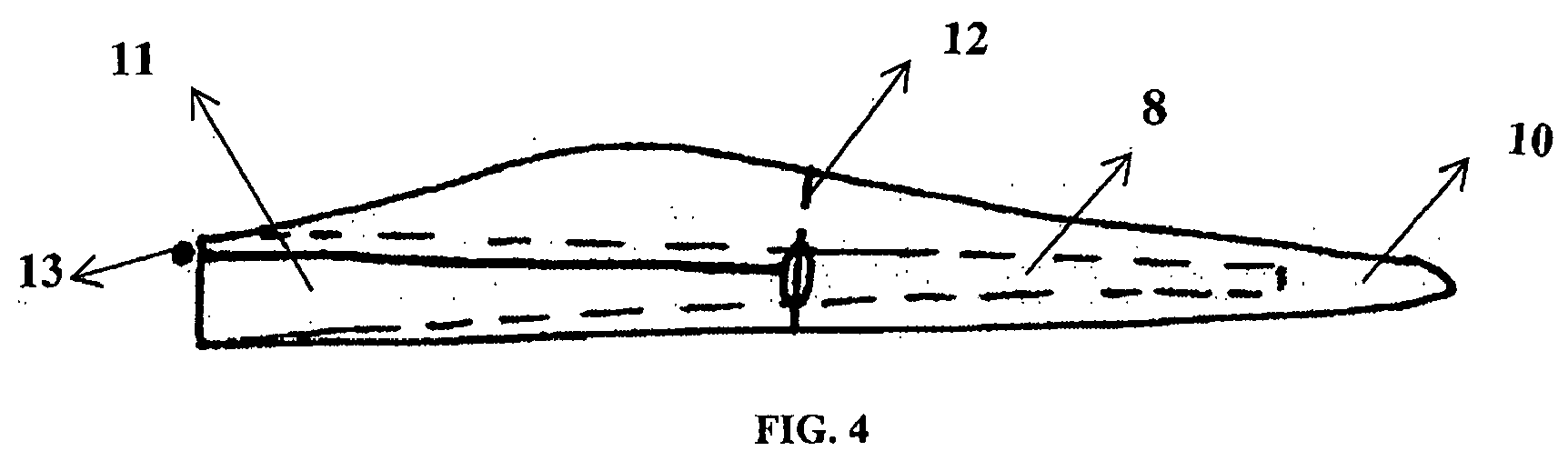
Figure 4 is a general view of a blade divided into two parts, with the transverse parts attached and with the controlled transmission system. -
Figure 5 shows the detail of an ultrasound sensor in the pin. -
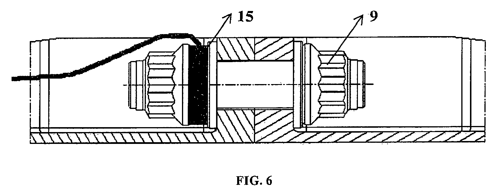
Figure 6 shows the detail of a load cell in the pin. -
Figure 7 shows the detail of a load cell between the front faces of two opposite inserts. - In
figure 1 , one can see part of a transversely subdivided blade (1) which shows its internal longitudinal structure (2) and that it is equipped with connection means (3) in its end sections. These connection means (3) are integrated in the structurally resistant part corresponding to the beam (4). When two end sections are joined, they give continuity to the blade (1), leaving only the connection means (3) without shell covering (5). These spaces are later covered with a fairing (5b) levelling the outer surface of the blade (1). -
Figure 3 shows the successive steps to prepare the connection means. First the metal insert (6) is prepared that has an axial drill (7) facing another insert in one of its ends. Later the metal insert (6) is shown joined, by adhesive, to a machined housing in the beam or resistant internal longitudinal structure (8). Finally, two metal inserts (6) are depicted with their axial drills (7) facing to receive pins and nuts (9) that make up the joining points. The aforementioned joint pins (9) work by traction. - All the induced loads in the blade tip modules (10) are transmitted through the transverse subdivision (12) of the blade (1). This subdivision is made up of a small number of joining elements (3) so that the load ends up passing only through the joint pins (9). In this way one may obtain the exact total load that goes through the subdivision and may get an excellent estimator of the load transmitted by the blade to the wind turbine. As shown in
figure 4 , monitoring the joining points corresponding to the transverse subdivision (12) with different sensors, the measurements of the sensors can be sent up to the root of the blade (11) using the inside of the beam (8). Finally, the measurements will arrive at the control point (12) in the hub (not shown in the figure). - An ultrasound sensor (14) is used in
figure 5 ; it sends an impulse that bounces off the end of the pin (9). The sensor measures the time that passes between the emission and reception of the impulse and transforms it into a preload measurement of the bolt that is sent to the control system (12). The ultrasound sensor (14) is at the end of the bolt (9) so that its signal can move lengthwise without any difficulty. - A load cell (15) is used in
figure 6 ; it consists of a metal washer from which its strain is measured. Later, the measurement of the load is transformed to that which the bolt is subject to and the result is sent to the control system (12). The location of the sensor (15) is such that it is easy to replace in case of damage. - In a second installation shown in
figure 7 , the load cell (15) is between the two inserts to be assembled.
Claims (5)
- Sensorised blade joint uses a series of sensors to control the load of the bolts during the life of the blade, characterised in that:a.- the sensors are available in at least one the multiple connection means in the transverse joint sectionb.- the signals measured by the sensors are transmitted to a control system that may or may not be located in the blade that controls the forces exerted on the jointc.- the signals transmitted to the control system are used to detect possible damages in the connectionsd.- the signals transmitted to the control system are used to control the loads transmitted to the wind turbinee.- the signals transmitted to the control system are used to store the load range, optimising the design with the real loads obtained.
- Sensorised blade joint, according to the first claim, characterised in that the sensors include at least one ultrasound sensor available at the end of the joint pin aligned with the resistant material that forms the insert.
- Sensorised blade joint, according to the first claim, characterised in that the sensors include at least one load cell located in a part near the pin or between the walls of the two facing inserts.
- Sensorised blade joint, according to the first claim, characterised in that the control system is located in the hub away from the distortions produced by blade rotation acceleration.
- Sensorised blade joint, according to the previous claim, characterised in that the control system is supplied with the measurements of the sensors leading their signal through the inside of the beam which forms the blade.
Priority Applications (1)
| Application Number | Priority Date | Filing Date | Title |
|---|---|---|---|
| PL08015978T PL2105609T3 (en) | 2007-09-14 | 2008-09-10 | Flange joint for blade sections of a wind turbine with load sensor on the bolts |
Applications Claiming Priority (1)
| Application Number | Priority Date | Filing Date | Title |
|---|---|---|---|
| ES200702442A ES2337645B1 (en) | 2007-09-14 | 2007-09-14 | SENSORIZED SHOVEL UNION. |
Publications (3)
| Publication Number | Publication Date |
|---|---|
| EP2105609A2 true EP2105609A2 (en) | 2009-09-30 |
| EP2105609A3 EP2105609A3 (en) | 2015-03-04 |
| EP2105609B1 EP2105609B1 (en) | 2017-05-03 |
Family
ID=40588239
Family Applications (1)
| Application Number | Title | Priority Date | Filing Date |
|---|---|---|---|
| EP08015978.3A Active EP2105609B1 (en) | 2007-09-14 | 2008-09-10 | Flange joint for blade sections of a wind turbine with load sensor on the bolts |
Country Status (5)
| Country | Link |
|---|---|
| US (1) | US20090116962A1 (en) |
| EP (1) | EP2105609B1 (en) |
| CN (1) | CN101457739B (en) |
| ES (2) | ES2337645B1 (en) |
| PL (1) | PL2105609T3 (en) |
Cited By (4)
| Publication number | Priority date | Publication date | Assignee | Title |
|---|---|---|---|---|
| US8376713B2 (en) | 2010-10-22 | 2013-02-19 | Mitsubishi Heavy Industries, Ltd. | Wind turbine rotor blade |
| EP4497582A1 (en) | 2023-07-28 | 2025-01-29 | Siemens Gamesa Renewable Energy A/S | Method for manufacturing a wind turbine blade and wind turbine blade |
| EP4497581A1 (en) | 2023-07-28 | 2025-01-29 | Siemens Gamesa Renewable Energy A/S | Method for manufacturing a wind turbine blade and wind turbine blade |
| US12607163B2 (en) | 2022-08-31 | 2026-04-21 | GE Vernova Renovables Espana, S.L.U. | System and method for detecting and responding to rotor blade damage in a wind turbine |
Families Citing this family (52)
| Publication number | Priority date | Publication date | Assignee | Title |
|---|---|---|---|---|
| ES2436664T3 (en) * | 2008-05-07 | 2014-01-03 | Vestas Wind Systems A/S | Sectional Shovel |
| WO2010023299A2 (en) * | 2008-08-31 | 2010-03-04 | Vestas Wind Systems A/S | A sectional blade |
| FR2948154B1 (en) * | 2009-07-16 | 2011-09-16 | Astrium Sas | DEVICE FOR ASSEMBLING WINDMILL BLADE RODS AND METHOD FOR CONNECTING WINDMILL BLADE TRUNCONS |
| US20100135796A1 (en) * | 2009-12-01 | 2010-06-03 | Venkateswara Rao Kavala | Monitoring joint efficiency in wind turbine rotor blades |
| WO2011067323A2 (en) * | 2009-12-02 | 2011-06-09 | Vestas Wind Systems A/S | Sectional wind turbine blade |
| DK2354543T3 (en) * | 2010-01-29 | 2016-02-01 | Siemens Ag | Method of attaching a load sensor to a surface of a rotor vane and rotor vane |
| DE102010040596A1 (en) * | 2010-09-10 | 2012-03-15 | Aloys Wobben | Removable rotor blade tip |
| ES2392523B2 (en) | 2011-05-13 | 2013-05-16 | Investigaciones Y Desarrollos Eólicos, S.L. | SYSTEM OF UNION OF COMPONENT SECTIONS OF AEROGENERATOR SHOES. |
| CN102269117B (en) * | 2011-07-05 | 2013-09-18 | 浙江运达风电股份有限公司 | Paddle of wind power generating set and wind power generating set |
| CN102269126B (en) * | 2011-07-14 | 2013-07-03 | 江苏新誉重工科技有限公司 | Electric variable pitch control system |
| US8454311B2 (en) * | 2011-09-29 | 2013-06-04 | General Electric Company | Wind turbine blade edge monitoring system |
| US8591187B2 (en) | 2011-12-06 | 2013-11-26 | General Electric Company | System and method for detecting loads transmitted through a blade root of a wind turbine rotor blade |
| US8430632B2 (en) | 2011-12-22 | 2013-04-30 | General Electric Company | System and method for pitching a rotor blade in a wind turbine |
| ES2425026B1 (en) * | 2012-04-03 | 2014-12-05 | Gamesa Innovation & Technology, S.L. | Method of manufacturing a component of a split blade of a wind turbine |
| US20140119914A1 (en) * | 2012-11-01 | 2014-05-01 | General Electric Company | Load control system and method |
| US9297357B2 (en) | 2013-04-04 | 2016-03-29 | General Electric Company | Blade insert for a wind turbine rotor blade |
| US9506452B2 (en) | 2013-08-28 | 2016-11-29 | General Electric Company | Method for installing a shear web insert within a segmented rotor blade assembly |
| WO2015058209A1 (en) | 2013-10-18 | 2015-04-23 | Tramontane Technologies, Inc. | Amplified optical circuit |
| EP2930350B1 (en) * | 2014-04-11 | 2018-02-14 | Siemens Aktiengesellschaft | Segmented rotor blade with a bolt connection |
| DE102014218518A1 (en) * | 2014-09-16 | 2016-03-17 | Dr. Johannes Heidenhain Gmbh | Device for detecting deformations of a rotor blade and method for mounting such a device |
| CN104747372A (en) * | 2015-04-20 | 2015-07-01 | 常州易驱动电气科技有限公司 | Electric flexible pitch control system |
| DE102016112633A1 (en) * | 2016-07-11 | 2018-01-11 | Wobben Properties Gmbh | Torsion angle measurement of a rotor blade |
| US10495058B2 (en) | 2017-02-21 | 2019-12-03 | General Electric Company | Joint assembly for rotor blade segments of a wind turbine |
| CN109681391B (en) * | 2017-10-18 | 2020-09-11 | 中车株洲电力机车研究所有限公司 | Blade root bolt fracture fault detection method and medium |
| US10961982B2 (en) | 2017-11-07 | 2021-03-30 | General Electric Company | Method of joining blade sections using thermoplastics |
| DE102017222444A1 (en) * | 2017-12-12 | 2019-06-13 | Robert Bosch Gmbh | Battery module, method of operating the same and its use |
| CN108590984B (en) * | 2018-04-04 | 2020-05-26 | 浙江运达风电股份有限公司 | Method and device for monitoring blade load of wind generating set |
| US11719222B2 (en) | 2018-08-03 | 2023-08-08 | General Electric Company | Method of joining wind turbine rotor blade segments via structural members |
| US10830207B2 (en) | 2018-08-28 | 2020-11-10 | General Electric Company | Spar configuration for jointed wind turbine rotor blades |
| DK3870834T3 (en) | 2018-10-25 | 2024-09-30 | Lm Wind Power As | Beam flange construction for a joined wind turbine blade |
| PL3874155T3 (en) | 2018-10-31 | 2023-11-20 | General Electric Company | Jointed wind turbine rotor blade having varying material combinations along its span for pin reinforcement |
| JP7221384B2 (en) | 2018-11-01 | 2023-02-13 | ゼネラル・エレクトリック・カンパニイ | Wind turbine jointed rotor blades with hollow chordally extending pins |
| EP3874143B1 (en) | 2018-11-01 | 2026-04-01 | General Electric Renovables España, S.L. | Compliant structures for jointed rotor blades |
| CN112955646B (en) | 2018-11-01 | 2024-10-11 | 通用电气可再生能源西班牙有限公司 | Scarf joint for wind turbine rotor blades |
| CN113286696A (en) | 2018-11-01 | 2021-08-20 | 通用电气公司 | Spacer material for reducing a bond gap between a beam structure and a blade shell of a segmented rotor blade |
| EP3874144B1 (en) | 2018-11-01 | 2023-08-02 | General Electric Company | Method for installing and retaining a bushing in a bearing block of a rotor blade joint |
| US11536246B2 (en) | 2018-11-01 | 2022-12-27 | General Electric Company | Span-wise extending pin for joining rotor blade segments |
| US11542917B2 (en) | 2018-12-11 | 2023-01-03 | General Electric Company | Beam structure for a segmented rotor blade having a transitioning shape |
| CN113165285A (en) | 2018-12-11 | 2021-07-23 | 通用电气公司 | Method for manufacturing a structural component for a blade segment of a rotor blade of a wind turbine |
| CA3121890A1 (en) | 2018-12-11 | 2020-06-18 | Louis Rondeau | Method for manufacturing a hollow composite structure, particularly a spar beam for a wind turbine rotor blade, and an associated mandrel |
| BR112021009996B1 (en) | 2018-12-11 | 2023-10-17 | General Electric Company | METHOD FOR PREVENTING MANUFACTURE AND STRUCTURAL COMPONENT DEFECTS FOR A BLADE SEGMENT OF A ROTOR BLADE OF A WIND TURBINE |
| DK3894191T3 (en) | 2018-12-11 | 2023-10-02 | Gen Electric | METHOD OF MANUFACTURE OF WIND COMPONENTS FOR WIND TURBINE ROTOR BLADES |
| DK3894691T3 (en) | 2018-12-13 | 2025-05-19 | General Electric Renovables Espana Sl | JOINTED ROTOR BLADE WITH A CHORD-WIDE EXTENDED PIN SUPPORTED VIA ONE OR MORE STRUCTURAL ELEMENTS |
| CN113167217B (en) | 2018-12-19 | 2024-06-07 | Lm风力发电公司 | Bonded rotor blade with internal support structure having different fiber orientations for pin reinforcement |
| EP3670902A1 (en) * | 2018-12-19 | 2020-06-24 | Siemens Gamesa Renewable Energy A/S | Wind turbine comprising at least one attachment arrangement |
| CN113167214A (en) | 2018-12-20 | 2021-07-23 | 通用电气公司 | Joint wind turbine rotor blade with spar caps constructed of different forms of material along its span |
| CN113167215B (en) | 2018-12-20 | 2024-06-18 | Lm风力发电公司 | Rotor blade segments fastened together via internal support structures defining gaps of variable size therebetween |
| DK3931436T3 (en) | 2019-03-01 | 2026-03-16 | General Electric Renovables Espana Sl | JOINTED WIND TURBINE ROTOR BLADE WITH EXTENDED PIN BUSHINGS DESIGNED TO MINIMIZE EXTENDED SPACES |
| US12385465B2 (en) * | 2020-08-28 | 2025-08-12 | Vestas Wind Systems A/S | Connection joint for a split wind turbine blade |
| GB202013647D0 (en) | 2020-08-31 | 2020-10-14 | Lm Wind Power As | Jointed wind turbine blade having improved transitions between varying material combinations |
| GB202020710D0 (en) | 2020-12-30 | 2021-02-10 | Gen Electric | Method of joining segments of a composite component |
| PL4036400T3 (en) * | 2021-01-27 | 2024-05-13 | Nordex Energy Se & Co. Kg | Wind turbine rotor blade |
Citations (2)
| Publication number | Priority date | Publication date | Assignee | Title |
|---|---|---|---|---|
| WO2001033075A1 (en) | 1999-11-03 | 2001-05-10 | Vestas Wind Systems A/S | Method of controlling the operation of a wind turbine and wind turbine for use in said method |
| WO2005010358A1 (en) | 2003-07-15 | 2005-02-03 | General Electric Company | Method and apparatus for wind turbine rotor load control based on shaft radial displacement |
Family Cites Families (15)
| Publication number | Priority date | Publication date | Assignee | Title |
|---|---|---|---|---|
| US4292835A (en) * | 1980-02-25 | 1981-10-06 | Raymond Engineering, Inc. | Calibration apparatus and method for strain measuring instruments |
| US4899591A (en) * | 1987-09-11 | 1990-02-13 | Sps Technologies, Inc. | Ultrasonic load indicating member, apparatus and method |
| GB2298624A (en) * | 1995-03-04 | 1996-09-11 | Nigel Howard Mckrill | Light controlled helicopter rotor blade |
| US6354152B1 (en) * | 1996-05-08 | 2002-03-12 | Edward Charles Herlik | Method and system to measure dynamic loads or stresses in aircraft, machines, and structures |
| DK58998A (en) * | 1998-04-30 | 1999-10-31 | Lm Glasfiber As | Windmill |
| JP2004011616A (en) * | 2002-06-11 | 2004-01-15 | Shin Meiwa Ind Co Ltd | Wind turbine blade structure of wind generator |
| US7160083B2 (en) * | 2003-02-03 | 2007-01-09 | General Electric Company | Method and apparatus for wind turbine rotor load control |
| DK200300670A (en) * | 2003-05-05 | 2004-11-06 | Lm Glasfiber As | Wind turbine with buoyancy regulating organs |
| EP1584817A1 (en) * | 2004-04-07 | 2005-10-12 | Gamesa Eolica, S.A. (Sociedad Unipersonal) | Wind turbine blade |
| US7086834B2 (en) * | 2004-06-10 | 2006-08-08 | General Electric Company | Methods and apparatus for rotor blade ice detection |
| DK176176B1 (en) * | 2004-11-24 | 2006-11-27 | Siemens Wind Power As | Method and connector for assembling a blade, preferably wind turbine blade, into sections |
| ES2265760B1 (en) * | 2005-03-31 | 2008-01-16 | GAMESA INNOVATION & TECHNOLOGY, S.L. | SHOVEL FOR WIND GENERATORS. |
| US20070193361A1 (en) * | 2006-02-20 | 2007-08-23 | Davie/Coffee Technologies, LLC | Compressive load sensor by capacitive measurement |
| DE102006036157B4 (en) * | 2006-08-01 | 2016-09-15 | Senvion Gmbh | calibration |
| EP1911968A1 (en) * | 2006-10-10 | 2008-04-16 | Ecotecnia Energias Renovables S.L. | Control system for a wind turbine and method of controlling said wind turbine |
-
2007
- 2007-09-14 ES ES200702442A patent/ES2337645B1/en not_active Expired - Fee Related
-
2008
- 2008-08-28 US US12/199,816 patent/US20090116962A1/en not_active Abandoned
- 2008-09-08 CN CN2008102156184A patent/CN101457739B/en active Active
- 2008-09-10 PL PL08015978T patent/PL2105609T3/en unknown
- 2008-09-10 EP EP08015978.3A patent/EP2105609B1/en active Active
- 2008-09-10 ES ES08015978.3T patent/ES2633414T3/en active Active
Patent Citations (2)
| Publication number | Priority date | Publication date | Assignee | Title |
|---|---|---|---|---|
| WO2001033075A1 (en) | 1999-11-03 | 2001-05-10 | Vestas Wind Systems A/S | Method of controlling the operation of a wind turbine and wind turbine for use in said method |
| WO2005010358A1 (en) | 2003-07-15 | 2005-02-03 | General Electric Company | Method and apparatus for wind turbine rotor load control based on shaft radial displacement |
Cited By (6)
| Publication number | Priority date | Publication date | Assignee | Title |
|---|---|---|---|---|
| US8376713B2 (en) | 2010-10-22 | 2013-02-19 | Mitsubishi Heavy Industries, Ltd. | Wind turbine rotor blade |
| US12607163B2 (en) | 2022-08-31 | 2026-04-21 | GE Vernova Renovables Espana, S.L.U. | System and method for detecting and responding to rotor blade damage in a wind turbine |
| EP4497582A1 (en) | 2023-07-28 | 2025-01-29 | Siemens Gamesa Renewable Energy A/S | Method for manufacturing a wind turbine blade and wind turbine blade |
| EP4497581A1 (en) | 2023-07-28 | 2025-01-29 | Siemens Gamesa Renewable Energy A/S | Method for manufacturing a wind turbine blade and wind turbine blade |
| WO2025026678A1 (en) | 2023-07-28 | 2025-02-06 | Siemens Gamesa Renewable Energy A/S | Method for manufacturing a wind turbine blade and wind turbine blade |
| WO2025026645A1 (en) | 2023-07-28 | 2025-02-06 | Siemens Gamesa Renewable Energy A/S | Method for manufacturing a wind turbine blade and wind turbine blade |
Also Published As
| Publication number | Publication date |
|---|---|
| CN101457739A (en) | 2009-06-17 |
| EP2105609A3 (en) | 2015-03-04 |
| ES2337645A1 (en) | 2010-04-27 |
| ES2633414T3 (en) | 2017-09-21 |
| EP2105609B1 (en) | 2017-05-03 |
| CN101457739B (en) | 2012-12-12 |
| PL2105609T3 (en) | 2017-10-31 |
| ES2337645B1 (en) | 2011-03-11 |
| US20090116962A1 (en) | 2009-05-07 |
Similar Documents
| Publication | Publication Date | Title |
|---|---|---|
| EP2105609B1 (en) | Flange joint for blade sections of a wind turbine with load sensor on the bolts | |
| DK2354543T3 (en) | Method of attaching a load sensor to a surface of a rotor vane and rotor vane | |
| EP2122430B1 (en) | Method for condition monitoring a rotor of a wind energy plant | |
| US8177505B2 (en) | Method for measuring a rotational position of a rotor blade of a wind turbine and measuring device | |
| US8181528B2 (en) | Method and system for ultrasonic inspection of gearbox ring gear | |
| EP2549454A2 (en) | System and method for detecting ice on a wind turbine rotor blade | |
| US20090193894A1 (en) | Apparatus for monitoring the rotational speed in a wind energy plant | |
| EP2659133B1 (en) | Wind turbine blade with cross-sectional sensors | |
| EP2659253B1 (en) | Method and apparatus for determining loads of a wind turbine blade | |
| CN106643906B (en) | Monitoring method and monitoring system for variable-pitch bearing | |
| JP2019184433A (en) | Method of measuring tightening soundness of bolted joints of windmill blades | |
| US20210199094A1 (en) | Sensor arrangement for a wind turbine | |
| KR20170042728A (en) | A Method for Early Error Detection in a Drive System, a System for Early Error Detection, Wind Generator Comprising the System and Use of the System | |
| AU2009297553A1 (en) | Stress analysis device for wind-turbine structure, computer-readable storage medium storing stress analysis program, and wind turbine generator system | |
| CN102472245B (en) | Wind turbine having a device for minimizing loads | |
| EP3296564A1 (en) | Drive device for wind turbines, drive device unit for wind turbines, and wind turbine | |
| US20170261402A1 (en) | Moment Bearing Test Device for Testing a Moment Bearing of a Wind Turbine and a Method Thereof | |
| CN101476538A (en) | Individual blade noise measurement system and method for wind turbines | |
| EP2110550A1 (en) | Sensorised multiplier | |
| US8227930B2 (en) | System and method for adjusting a bending moment of a shaft in a wind turbine | |
| EP4731896A1 (en) | Wind turbine and method of operating a wind turbine | |
| EP3514397B1 (en) | A bearing arrangement and a wind turbine | |
| EP4715195A1 (en) | A wind turbine | |
| Zhang et al. | Non-invasive condition monitoring and diagnostics techniques for wind turbines | |
| CN115824057B (en) | Flange connection bolt monitoring system and monitoring method |
Legal Events
| Date | Code | Title | Description |
|---|---|---|---|
| PUAI | Public reference made under article 153(3) epc to a published international application that has entered the european phase |
Free format text: ORIGINAL CODE: 0009012 |
|
| AK | Designated contracting states |
Kind code of ref document: A2 Designated state(s): AT BE BG CH CY CZ DE DK EE ES FI FR GB GR HR HU IE IS IT LI LT LU LV MC MT NL NO PL PT RO SE SI SK TR |
|
| AX | Request for extension of the european patent |
Extension state: AL BA MK RS |
|
| RAP1 | Party data changed (applicant data changed or rights of an application transferred) |
Owner name: GAMESA INNOVATION & TECHNOLOGY, S.L. |
|
| PUAL | Search report despatched |
Free format text: ORIGINAL CODE: 0009013 |
|
| AK | Designated contracting states |
Kind code of ref document: A3 Designated state(s): AT BE BG CH CY CZ DE DK EE ES FI FR GB GR HR HU IE IS IT LI LT LU LV MC MT NL NO PL PT RO SE SI SK TR |
|
| AX | Request for extension of the european patent |
Extension state: AL BA MK RS |
|
| RIC1 | Information provided on ipc code assigned before grant |
Ipc: F16L 23/036 20060101ALI20150128BHEP Ipc: F16B 31/02 20060101ALI20150128BHEP Ipc: F03D 11/00 20060101AFI20150128BHEP Ipc: F03D 1/06 20060101ALI20150128BHEP Ipc: F03D 7/00 20060101ALI20150128BHEP |
|
| 17P | Request for examination filed |
Effective date: 20150724 |
|
| RBV | Designated contracting states (corrected) |
Designated state(s): AT BE BG CH CY CZ DE DK EE ES FI FR GB GR HR HU IE IS IT LI LT LU LV MC MT NL NO PL PT RO SE SI SK TR |
|
| RBV | Designated contracting states (corrected) |
Designated state(s): AT BE BG CH CY CZ DE DK EE ES FI FR GB GR HR HU IE IS IT LI LT LU LV MC MT NL NO PL PT RO SE SI SK TR |
|
| RBV | Designated contracting states (corrected) |
Designated state(s): AT BE BG CH CY CZ DE DK EE ES FI FR GB GR HR HU IE IS IT LI LT LU LV MC MT NL NO PL PT RO SE SI SK TR |
|
| AKX | Designation fees paid |
Designated state(s): AT BE BG CH CY CZ DE DK EE ES FI FR GB GR HR HU IE IS IT LI LT LU LV MC MT NL NO PL PT RO SE SI SK TR |
|
| AXX | Extension fees paid |
Extension state: RS Extension state: BA Extension state: AL Extension state: MK |
|
| REG | Reference to a national code |
Ref country code: DE Ref legal event code: R079 Ref document number: 602008050015 Country of ref document: DE Free format text: PREVIOUS MAIN CLASS: F03D0011000000 Ipc: F03D0007020000 |
|
| GRAP | Despatch of communication of intention to grant a patent |
Free format text: ORIGINAL CODE: EPIDOSNIGR1 |
|
| RIC1 | Information provided on ipc code assigned before grant |
Ipc: F16L 23/036 20060101ALI20161129BHEP Ipc: F03D 1/06 20060101ALI20161129BHEP Ipc: F03D 17/00 20160101ALI20161129BHEP Ipc: F03D 7/02 20060101AFI20161129BHEP Ipc: F16B 31/02 20060101ALI20161129BHEP |
|
| INTG | Intention to grant announced |
Effective date: 20161221 |
|
| GRAS | Grant fee paid |
Free format text: ORIGINAL CODE: EPIDOSNIGR3 |
|
| GRAA | (expected) grant |
Free format text: ORIGINAL CODE: 0009210 |
|
| AK | Designated contracting states |
Kind code of ref document: B1 Designated state(s): AT BE BG CH CY CZ DE DK EE ES FI FR GB GR HR HU IE IS IT LI LT LU LV MC MT NL NO PL PT RO SE SI SK TR |
|
| REG | Reference to a national code |
Ref country code: GB Ref legal event code: FG4D |
|
| REG | Reference to a national code |
Ref country code: AT Ref legal event code: REF Ref document number: 890300 Country of ref document: AT Kind code of ref document: T Effective date: 20170515 Ref country code: CH Ref legal event code: EP |
|
| REG | Reference to a national code |
Ref country code: IE Ref legal event code: FG4D |
|
| REG | Reference to a national code |
Ref country code: DE Ref legal event code: R096 Ref document number: 602008050015 Country of ref document: DE |
|
| REG | Reference to a national code |
Ref country code: SE Ref legal event code: TRGR |
|
| REG | Reference to a national code |
Ref country code: FR Ref legal event code: PLFP Year of fee payment: 10 |
|
| REG | Reference to a national code |
Ref country code: NL Ref legal event code: MP Effective date: 20170503 |
|
| REG | Reference to a national code |
Ref country code: AT Ref legal event code: MK05 Ref document number: 890300 Country of ref document: AT Kind code of ref document: T Effective date: 20170503 |
|
| REG | Reference to a national code |
Ref country code: ES Ref legal event code: FG2A Ref document number: 2633414 Country of ref document: ES Kind code of ref document: T3 Effective date: 20170921 |
|
| REG | Reference to a national code |
Ref country code: LT Ref legal event code: MG4D |
|
| PG25 | Lapsed in a contracting state [announced via postgrant information from national office to epo] |
Ref country code: GR Free format text: LAPSE BECAUSE OF FAILURE TO SUBMIT A TRANSLATION OF THE DESCRIPTION OR TO PAY THE FEE WITHIN THE PRESCRIBED TIME-LIMIT Effective date: 20170804 Ref country code: HR Free format text: LAPSE BECAUSE OF FAILURE TO SUBMIT A TRANSLATION OF THE DESCRIPTION OR TO PAY THE FEE WITHIN THE PRESCRIBED TIME-LIMIT Effective date: 20170503 Ref country code: AT Free format text: LAPSE BECAUSE OF FAILURE TO SUBMIT A TRANSLATION OF THE DESCRIPTION OR TO PAY THE FEE WITHIN THE PRESCRIBED TIME-LIMIT Effective date: 20170503 Ref country code: NO Free format text: LAPSE BECAUSE OF FAILURE TO SUBMIT A TRANSLATION OF THE DESCRIPTION OR TO PAY THE FEE WITHIN THE PRESCRIBED TIME-LIMIT Effective date: 20170803 Ref country code: LT Free format text: LAPSE BECAUSE OF FAILURE TO SUBMIT A TRANSLATION OF THE DESCRIPTION OR TO PAY THE FEE WITHIN THE PRESCRIBED TIME-LIMIT Effective date: 20170503 |
|
| PG25 | Lapsed in a contracting state [announced via postgrant information from national office to epo] |
Ref country code: BG Free format text: LAPSE BECAUSE OF FAILURE TO SUBMIT A TRANSLATION OF THE DESCRIPTION OR TO PAY THE FEE WITHIN THE PRESCRIBED TIME-LIMIT Effective date: 20170803 Ref country code: IS Free format text: LAPSE BECAUSE OF FAILURE TO SUBMIT A TRANSLATION OF THE DESCRIPTION OR TO PAY THE FEE WITHIN THE PRESCRIBED TIME-LIMIT Effective date: 20170903 Ref country code: NL Free format text: LAPSE BECAUSE OF FAILURE TO SUBMIT A TRANSLATION OF THE DESCRIPTION OR TO PAY THE FEE WITHIN THE PRESCRIBED TIME-LIMIT Effective date: 20170503 Ref country code: LV Free format text: LAPSE BECAUSE OF FAILURE TO SUBMIT A TRANSLATION OF THE DESCRIPTION OR TO PAY THE FEE WITHIN THE PRESCRIBED TIME-LIMIT Effective date: 20170503 |
|
| PG25 | Lapsed in a contracting state [announced via postgrant information from national office to epo] |
Ref country code: CZ Free format text: LAPSE BECAUSE OF FAILURE TO SUBMIT A TRANSLATION OF THE DESCRIPTION OR TO PAY THE FEE WITHIN THE PRESCRIBED TIME-LIMIT Effective date: 20170503 Ref country code: RO Free format text: LAPSE BECAUSE OF FAILURE TO SUBMIT A TRANSLATION OF THE DESCRIPTION OR TO PAY THE FEE WITHIN THE PRESCRIBED TIME-LIMIT Effective date: 20170503 Ref country code: SK Free format text: LAPSE BECAUSE OF FAILURE TO SUBMIT A TRANSLATION OF THE DESCRIPTION OR TO PAY THE FEE WITHIN THE PRESCRIBED TIME-LIMIT Effective date: 20170503 Ref country code: EE Free format text: LAPSE BECAUSE OF FAILURE TO SUBMIT A TRANSLATION OF THE DESCRIPTION OR TO PAY THE FEE WITHIN THE PRESCRIBED TIME-LIMIT Effective date: 20170503 Ref country code: DK Free format text: LAPSE BECAUSE OF FAILURE TO SUBMIT A TRANSLATION OF THE DESCRIPTION OR TO PAY THE FEE WITHIN THE PRESCRIBED TIME-LIMIT Effective date: 20170503 |
|
| REG | Reference to a national code |
Ref country code: DE Ref legal event code: R097 Ref document number: 602008050015 Country of ref document: DE |
|
| PLBE | No opposition filed within time limit |
Free format text: ORIGINAL CODE: 0009261 |
|
| STAA | Information on the status of an ep patent application or granted ep patent |
Free format text: STATUS: NO OPPOSITION FILED WITHIN TIME LIMIT |
|
| 26N | No opposition filed |
Effective date: 20180206 |
|
| REG | Reference to a national code |
Ref country code: CH Ref legal event code: PL |
|
| PG25 | Lapsed in a contracting state [announced via postgrant information from national office to epo] |
Ref country code: SI Free format text: LAPSE BECAUSE OF FAILURE TO SUBMIT A TRANSLATION OF THE DESCRIPTION OR TO PAY THE FEE WITHIN THE PRESCRIBED TIME-LIMIT Effective date: 20170503 Ref country code: MC Free format text: LAPSE BECAUSE OF FAILURE TO SUBMIT A TRANSLATION OF THE DESCRIPTION OR TO PAY THE FEE WITHIN THE PRESCRIBED TIME-LIMIT Effective date: 20170503 |
|
| REG | Reference to a national code |
Ref country code: IE Ref legal event code: MM4A |
|
| REG | Reference to a national code |
Ref country code: BE Ref legal event code: MM Effective date: 20170930 |
|
| PG25 | Lapsed in a contracting state [announced via postgrant information from national office to epo] |
Ref country code: LU Free format text: LAPSE BECAUSE OF NON-PAYMENT OF DUE FEES Effective date: 20170910 |
|
| PG25 | Lapsed in a contracting state [announced via postgrant information from national office to epo] |
Ref country code: IE Free format text: LAPSE BECAUSE OF NON-PAYMENT OF DUE FEES Effective date: 20170910 Ref country code: LI Free format text: LAPSE BECAUSE OF NON-PAYMENT OF DUE FEES Effective date: 20170930 Ref country code: CH Free format text: LAPSE BECAUSE OF NON-PAYMENT OF DUE FEES Effective date: 20170930 |
|
| PG25 | Lapsed in a contracting state [announced via postgrant information from national office to epo] |
Ref country code: BE Free format text: LAPSE BECAUSE OF NON-PAYMENT OF DUE FEES Effective date: 20170930 |
|
| REG | Reference to a national code |
Ref country code: FR Ref legal event code: PLFP Year of fee payment: 11 |
|
| PG25 | Lapsed in a contracting state [announced via postgrant information from national office to epo] |
Ref country code: MT Free format text: LAPSE BECAUSE OF NON-PAYMENT OF DUE FEES Effective date: 20170910 |
|
| PG25 | Lapsed in a contracting state [announced via postgrant information from national office to epo] |
Ref country code: HU Free format text: LAPSE BECAUSE OF FAILURE TO SUBMIT A TRANSLATION OF THE DESCRIPTION OR TO PAY THE FEE WITHIN THE PRESCRIBED TIME-LIMIT; INVALID AB INITIO Effective date: 20080910 |
|
| PG25 | Lapsed in a contracting state [announced via postgrant information from national office to epo] |
Ref country code: CY Free format text: LAPSE BECAUSE OF NON-PAYMENT OF DUE FEES Effective date: 20170503 |
|
| PG25 | Lapsed in a contracting state [announced via postgrant information from national office to epo] |
Ref country code: TR Free format text: LAPSE BECAUSE OF FAILURE TO SUBMIT A TRANSLATION OF THE DESCRIPTION OR TO PAY THE FEE WITHIN THE PRESCRIBED TIME-LIMIT Effective date: 20170503 |
|
| PG25 | Lapsed in a contracting state [announced via postgrant information from national office to epo] |
Ref country code: PT Free format text: LAPSE BECAUSE OF FAILURE TO SUBMIT A TRANSLATION OF THE DESCRIPTION OR TO PAY THE FEE WITHIN THE PRESCRIBED TIME-LIMIT Effective date: 20170503 |
|
| REG | Reference to a national code |
Ref country code: DE Ref legal event code: R082 Ref document number: 602008050015 Country of ref document: DE Ref country code: DE Ref legal event code: R081 Ref document number: 602008050015 Country of ref document: DE Owner name: SIEMENS GAMESA RENEWABLE ENERGY INNOVATION & T, ES Free format text: FORMER OWNER: GAMESA INNOVATION & TECHNOLOGY, S.L., SARRIGUREN, ES |
|
| PGFP | Annual fee paid to national office [announced via postgrant information from national office to epo] |
Ref country code: IT Payment date: 20210920 Year of fee payment: 14 |
|
| PGFP | Annual fee paid to national office [announced via postgrant information from national office to epo] |
Ref country code: SE Payment date: 20210907 Year of fee payment: 14 |
|
| REG | Reference to a national code |
Ref country code: SE Ref legal event code: EUG |
|
| PG25 | Lapsed in a contracting state [announced via postgrant information from national office to epo] |
Ref country code: SE Free format text: LAPSE BECAUSE OF NON-PAYMENT OF DUE FEES Effective date: 20220911 |
|
| PG25 | Lapsed in a contracting state [announced via postgrant information from national office to epo] |
Ref country code: IT Free format text: LAPSE BECAUSE OF NON-PAYMENT OF DUE FEES Effective date: 20220910 |
|
| PGFP | Annual fee paid to national office [announced via postgrant information from national office to epo] |
Ref country code: DE Payment date: 20240926 Year of fee payment: 17 Ref country code: FI Payment date: 20240926 Year of fee payment: 17 |
|
| PGFP | Annual fee paid to national office [announced via postgrant information from national office to epo] |
Ref country code: GB Payment date: 20240924 Year of fee payment: 17 |
|
| PGFP | Annual fee paid to national office [announced via postgrant information from national office to epo] |
Ref country code: FR Payment date: 20240925 Year of fee payment: 17 |
|
| PGFP | Annual fee paid to national office [announced via postgrant information from national office to epo] |
Ref country code: PL Payment date: 20240819 Year of fee payment: 17 |
|
| PGFP | Annual fee paid to national office [announced via postgrant information from national office to epo] |
Ref country code: ES Payment date: 20241021 Year of fee payment: 17 |
|
| PG25 | Lapsed in a contracting state [announced via postgrant information from national office to epo] |
Ref country code: FI Free format text: LAPSE BECAUSE OF NON-PAYMENT OF DUE FEES Effective date: 20250910 |