EP2105361A1 - Door-lock control system, door-lock control method and program - Google Patents
Door-lock control system, door-lock control method and program Download PDFInfo
- Publication number
- EP2105361A1 EP2105361A1 EP20090153218 EP09153218A EP2105361A1 EP 2105361 A1 EP2105361 A1 EP 2105361A1 EP 20090153218 EP20090153218 EP 20090153218 EP 09153218 A EP09153218 A EP 09153218A EP 2105361 A1 EP2105361 A1 EP 2105361A1
- Authority
- EP
- European Patent Office
- Prior art keywords
- door
- vehicle position
- public security
- unit
- vehicle
- Prior art date
- Legal status (The legal status is an assumption and is not a legal conclusion. Google has not performed a legal analysis and makes no representation as to the accuracy of the status listed.)
- Granted
Links
- 238000000034 method Methods 0.000 title claims description 8
- 238000012545 processing Methods 0.000 claims abstract description 72
- 238000001514 detection method Methods 0.000 claims abstract description 15
- 238000004590 computer program Methods 0.000 claims description 3
- 230000006870 function Effects 0.000 description 39
- 238000004891 communication Methods 0.000 description 9
- 230000003287 optical effect Effects 0.000 description 3
- 238000010586 diagram Methods 0.000 description 2
- 230000015654 memory Effects 0.000 description 2
- 206010039203 Road traffic accident Diseases 0.000 description 1
- 230000007423 decrease Effects 0.000 description 1
- 230000001419 dependent effect Effects 0.000 description 1
- 238000011161 development Methods 0.000 description 1
- 230000018109 developmental process Effects 0.000 description 1
- 230000007246 mechanism Effects 0.000 description 1
- 238000012986 modification Methods 0.000 description 1
- 230000004048 modification Effects 0.000 description 1
- 230000008569 process Effects 0.000 description 1
- 230000001105 regulatory effect Effects 0.000 description 1
- 230000003936 working memory Effects 0.000 description 1
Images

Classifications
-
- B—PERFORMING OPERATIONS; TRANSPORTING
- B60—VEHICLES IN GENERAL
- B60R—VEHICLES, VEHICLE FITTINGS, OR VEHICLE PARTS, NOT OTHERWISE PROVIDED FOR
- B60R25/00—Fittings or systems for preventing or indicating unauthorised use or theft of vehicles
- B60R25/20—Means to switch the anti-theft system on or off
- B60R25/24—Means to switch the anti-theft system on or off using electronic identifiers containing a code not memorised by the user
-
- B—PERFORMING OPERATIONS; TRANSPORTING
- B60—VEHICLES IN GENERAL
- B60R—VEHICLES, VEHICLE FITTINGS, OR VEHICLE PARTS, NOT OTHERWISE PROVIDED FOR
- B60R25/00—Fittings or systems for preventing or indicating unauthorised use or theft of vehicles
- B60R25/20—Means to switch the anti-theft system on or off
- B60R25/24—Means to switch the anti-theft system on or off using electronic identifiers containing a code not memorised by the user
- B60R25/241—Means to switch the anti-theft system on or off using electronic identifiers containing a code not memorised by the user whereby access privileges are related to the identifiers
-
- B—PERFORMING OPERATIONS; TRANSPORTING
- B60—VEHICLES IN GENERAL
- B60R—VEHICLES, VEHICLE FITTINGS, OR VEHICLE PARTS, NOT OTHERWISE PROVIDED FOR
- B60R25/00—Fittings or systems for preventing or indicating unauthorised use or theft of vehicles
- B60R25/30—Detection related to theft or to other events relevant to anti-theft systems
- B60R25/33—Detection related to theft or to other events relevant to anti-theft systems of global position, e.g. by providing GPS coordinates
Definitions
- the present invention relates to door-lock control systems, door-lock control methods, and programs.
- a plurality of doors are mounted in a freely-openable and closable way to get in and out the vehicles.
- a driver can lock and unlock the doors by inserting a key into a keyhole of a door and turning the key to operate a door-lock device.
- a keyless entry system achieves the door-lock device to be operated by a remote operation, in which a key for the remote operation, i.e., a remote operation key, includes a lock button and an unlock button.
- the doors are locked by pressing the lock button and unlocked by pressing the unlock button through an operation of the remote operation key.
- the door-lock device can be operated without pressing the lock button or the unlock button.
- the doors are locked and unlocked only by approaching a vehicle with the remote operation key and touching a door handle or the like (refer to Japanese Patent Application; Publication No. JP-A 2005-54487 , for example).
- the present invention has been devised in order to solve the above problems, and thus it is an object thereof is to provide a door-lock control system, a door-lock control method and a program that can increase the security during door opening.
- the present invention provides a door-lock control system including: a door lock device for locking and unlocking doors of a vehicle; a current position detection unit that detects a vehicle position; a data recording unit in which map data and public security information associated with the map data are recorded; a public security situation determination processing unit that reads the vehicle position detected by the current position detection unit and determines a public security situation at the vehicle position on the basis of the public security information recorded in the data recording unit; and a function setting processing unit that sets, according to the public security situation at the vehicle position, a function limit state that limits unlocking when a door-unlock operation has been performed by an operation unit.
- the public security situation at the vehicle position is determined on the basis of the public security information recorded in the data recording unit, and the function limit state that limits unlocking when the door-unlock operation has been performed by the operation unit is set according to the public security situation at the vehicle position. Therefore, the security during door opening can increase.
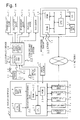
- FIG. 1 is a block diagram showing a navigation system in accordance with an embodiment of the present invention.
- FIG. 2 is a flowchart showing an operation of a function limit processing unit in accordance with the embodiment of the present invention.
- FIG. 1 is a block diagram showing a navigation system in accordance with the embodiment of the present invention.
- reference numeral 14 denotes an information terminal, for example, a navigation device serving as an in-vehicle device installed in a vehicle.
- Reference numeral 43 denotes a door opening and closing system.
- Reference numeral 63 denotes a network.
- Reference numeral 51 denotes an information center serving as an information provider.
- the navigation system includes the navigation device 14, the door opening and closing system 43, the network 63, the information center 51, and the like.
- the navigation device 14 includes; a GPS (Global Positioning System) sensor 15 serving as a current position detection unit that detects a vehicle position and a vehicle direction; a data recording unit 16 serving as an information recording unit in which map data and various other information are recorded; a navigation processing unit 17 that performs various kinds of arithmetic processing such as navigation processing and the like based on inputted information; an operation unit 34 serving as a first input unit for performing a predetermined input through an operation of a driver as an operator; a display unit 35 serving as a first output unit for performing various kinds of display using an image displayed on a screen (not shown) to perform a notification to the driver; a voice input unit 36 serving as a second input unit for performing a predetermined input by voice; a voice output unit 37 serving as a second output unit for performing various kinds of display by voice to perform a notification to the driver; and a communication unit 38 serving as a transmitting and receiving unit that functions as a communication terminal.
- a GPS Global Positioning System
- the GPS sensor 15, the data recoding unit 16, the operation unit 34, the display unit 35, the voice input unit 36, the voice output unit 37, and the communication unit 38 are connected to the navigation processing unit 17. Further, a speed sensor 41 serving as a speed detection unit that detects a vehicle speed is connected to the navigation processing unit 17.
- the vehicle direction is detected by the GPS sensor 15; however, a direction sensor (not shown) serving as a direction detection unit can be independently installed so that the vehicle direction can be detected by the direction sensor.
- the GPS sensor 15 also detects a time.
- Map data, statistical data, driven history data, registered point data indicating a point registered by the driver, voice data for outputting a predetermined information by the voice output unit 37, various other data such as public security information, and the like are recorded in the data recording unit 16.
- the map data includes node data regarding a node, road data regarding a road link, search data that has been processed for a search, intersection data regarding an intersection, facility data regarding a facility, and the like.
- the data is recorded in a data base installed in the data recording unit 16.
- the public security information is recorded associated with the map data.
- the data recording unit 16 includes a disk (not shown) such as a hard disk, a CD, a DVD, an optical disk, and the like as well as a head (not shown) such as a reading/writing head for reading and writing the various kinds of data and the like. Further, a memory card or the like can be used for the data recording unit 16.
- the navigation processing unit 17 includes: a CPU 31 serving both as a control device that performs an overall control of the navigation device 14 and as an arithmetic device; a RAM 32 that the CPU 31 uses as a working memory to perform various kinds of arithmetic processing; a ROM 33 in which a program for control and various other programs for performing a route search to a destination, search route guidance, i.e., route guidance, and the like are recorded; and a flash memory (not shown) that is used to record various kinds of data, programs, and the like.
- the operation unit 34 is used for achieving various kinds of functions in the navigation device 14 through an operation of the driver.
- the operating unit 34 includes a remote control, a keyboard, a mouse, and the like that are installed independently of the navigation device 14, as well as a switch, a button, a key, a dial, and the like serving as operating elements by parts formed on a casing of the navigation device 14 and the like.
- a display is used for the display unit 35.
- a touch panel further having a function of the operation unit can be used for the operation unit 34 and the display unit 35.
- a key, a switch, a button, and the like serving as operating elements as images are displayed on a screen, so that a predetermined input operation can be performed by touching the key, the switch, the button, or the like.
- the voice input unit 36 includes a microphone (not shown) or the like, and necessary information can be inputted by voice.
- the voice output unit 37 includes a voice synthesizer and a speaker, (not shown), and various kinds of information are outputted by voice from the voice output unit 37.
- the communication unit 38 includes a beacon receiver, a radio receiver, and the like.
- the beacon receiver receives various kinds of information such as traffic information, general information, and the like, which are transmitted from a road traffic information center (not shown) as an information provider such as a VICS (a registered trademark, Vehicle Information and Communication System) center, by a radio beacon, an optical beacon, or the like via a radio beacon device, an optical beacon device, or the like installed along a road.
- the radio receiver receives radio broadcasting such as FM multiple broadcasting via a radio station.
- the traffic information includes congestion information, regulatory information, parking information, traffic accident information, service area congestion state information, and the like, whereas the general information includes news, weather forecast, and the like.
- the communication unit 38 can receive various kinds of information such as traffic information, general information, and the like from the information center 51.
- the information center 51 includes a server 53, a communication unit 57 that is connected to the server 53, a data base (DB) 58 serving as an information recording unit, and the like.
- the server 53 includes a CPU 54 serving both as a control device and as an arithmetic device, a RAM 55, a ROM 56, and the like.
- the same data as the various kinds of data recorded in the data recording unit 16 is recorded in the data base 58.
- the information center 51 can provide the driven history data collected from a plurality of vehicles (an own vehicle or other vehicles) in real time.
- the navigation system, the navigation processing unit 17, the CPUs 31 and 54, the server 53, and the like function as a computer independently or by combining two or more units, and perform various kinds of processing based on various kinds of programs, data, and the like.
- a recording medium includes the data recording unit 16, the RAMs 32 and 55, the ROMs 33 and 56, the data base 58, the flash memory, and the like. Further, an MPU or the like can be used as the arithmetic device in place of the CPUs 31 and 54.
- an initialization processing unit (not shown) of the CPU 31 performs initialization processing to read the vehicle position and the vehicle direction detected by the GPS sensor 15 and initialize various kinds of data.
- a matching processing unit (not shown) of the CPU 31 performs matching processing to locate the vehicle position by determining on which road link the vehicle position is positioned based on the track of the read vehicle position, the shape and the arrangement of each of road links that form a road in the vicinity of the vehicle position, and the like.
- a basic information acquisition processing unit (not shown) of the CPU 31 performs basic information acquisition processing to acquire the map data by reading the data from the data recording unit 16 or by receiving the data from the information center 51 or the like via the communication unit 38.
- a display processing unit (not shown) of the CPU 31 performs display processing to form a map screen in the display unit 35 and display the vehicle position, the map of the vicinity of the vehicle position, and the vehicle direction on the map screen. Consequently, the driver can drive the vehicle following the vehicle position, the map of the vicinity of the vehicle position, and the vehicle direction.
- a destination setting processing unit (not shown) of the CPU 31 performs destination setting processing to set a destination. Also, it is possible to set a departure point through an input if necessary. Further, it is possible to register a specified point in advance and set the registered point as the destination.
- a route search processing unit (not shown) of the CPU 31 performs route search processing to read the vehicle position, the destination, the search condition, and the like, read the search data and the like from the data recording unit 16, search a route from the departure point represented by the vehicle position to the destination under the search condition on the basis of the vehicle position, the destination, and the search data, and output route data indicating the search route.
- a route in which a total of the link cost assigned to each road link is the smallest is set as the search route.
- a guidance processing unit (not shown) of the CPU 31 performs guidance processing to perform route guidance.
- a route display processing unit of the guidance processing unit performs route display processing to read the route data and display the search route on the map screen according to the route data.
- a voice output processing unit of the guidance processing unit performs voice output processing to perform the route guidance by outputting the search route by voice from the voice output unit 37, if necessary.
- the display processing unit Upon receiving the traffic information via the communication unit 38, the display processing unit converts the traffic information into a congestion zone as a traffic condition indicator and displays the congestion zone along a road on the map screen.
- the congestion zone is displayed extended from the starting point to the ending point of the congestion, and the color of the congestion zone is changed in red, orange, green, or the like according to the level of the congestion.
- the driver can know congestion conditions of the roads in the route to be traveled by the vehicle, the search route, or the like.
- a plurality of doors are mounted in a freely-openable and closable way to get in and out the vehicles.
- 5 doors of a front-right door 71, a front-left door 72, a rear-right door 73, a rear-left door 74 and a back-door 75 are mounted.
- a driver seat is mounted on the side of the front-right door 71 in a right-hand-drive vehicle and on the side of the front-left door 72 in a left-hand-drive vehicle.
- the driver seat is mounted on the side of the front-right door 71.
- a keyhole (not shown) is formed near an exterior handle of the front-right door 71 and, if necessary, an exterior handle of the front-left door 72.
- the door opening and closing system 43 includes a door-lock device 44, a key 46 serving as a first operation unit that is equipped to operate the door lock device 44, an operation button 47 serving as a second operation unit.
- the key 46 includes a key part (not shown) so that the key 46 can be operated by a manual operation outside the vehicle.
- the door-lock device 44 includes a receiving unit 65 for receiving a remote operation signal and a door-lock operating unit 66, which is operated on the basis of the remote operation signal, for locking and unlocking the doors. Consequently, the driver can operate the door-lock operating unit 66 by inserting the key part into the keyhole and turning the key 46 outside the vehicle.
- a door-lock motor (not shown) serving as a drive unit for door-lock, which is mounted in each door, is activated and a lock mechanism (not shown) is operated to lock or unlock the doors.
- the key 46 can be used as a remote operation key and operated by a remote operation outside the vehicle.
- the key 46 includes a lock button b1 serving as a first operating element, an unlock button b2 serving as a second operating element, and a transmitting unit 48 for generating the remote operation signal to lock and unlock the doors and transmitting the signal to the door lock device 44.
- the transmitting unit 48 when the driver presses the lock button b1 outside the vehicle, the transmitting unit 48 generates the remote operation signal and transmits the signal to the door lock device 44.
- the receiving unit 65 receives the remote operation signal and the door-lock operating unit 66 locks the doors according to the remote operation signal.
- the transmitting unit 48 When the driver presses the unlock button b2 outside the vehicle, the transmitting unit 48 generates the remote operation signal and transmits the signal to the door lock device 44.
- the receiving unit 65 receives the remote operation signal and the door-lock operating unit 66 unlocks the doors according to the remote operation signal.
- the keyless entry system includes the door opening and closing system 43.
- the door-lock operating unit 66 can be operated without pressing the lock button b1 or the unlock button b2.
- the transmitting unit 48 generates the remote operation signal at all times.
- the receiving unit 65 receives the remote operation signal from the vicinity of the vehicle and transmits the signal to the door-lock operating unit 66. Then, the door-lock operating unit 66 turns to a standby state for operation of locking and unlocking the doors. If the driver having the key 46 touches the handle serving as a third operation unit of the door or the like outside but in the vicinity of the vehicle, for example, the standby state for operation is cancelled and the door-lock operating unit 66 is operated to lock or unlock the doors.
- the operation button 47 can be operated in the vehicle. To this end, the operation button 47 is mounted at a specified place of the vehicle, which is inside the front-right door 71 in this embodiment. When the driver presses the button, the door-lock operating unit 66 is operated and the doors can be locked or unlocked.
- the driver inserts the key part into the keyhole and turns the key 46 outside the vehicle to operate the door-lock operating unit 66.
- the driver presses the unlock button b2 of the key 46 or touches the handle or the like of the door outside but in the vicinity of the vehicle to operate the door-lock operating unit 66.
- a function of the door-unlock is limited in the poor security area.
- a function limit processing unit (not shown) of the CPU31 performs function limit processing.
- FIG. 2 is a flowchart showing an operation of the function limit processing unit in accordance with the embodiment of the present invention.
- a vehicle position acquisition condition determination processing unit of the function limit processing unit performs vehicle position acquisition condition determination processing to determine that a predetermined vehicle position acquisition condition has been met if the ignition of the vehicle has been switched off. If the ignition is switched off and the vehicle position information acquisition condition is met, a vehicle position acquisition processing unit of the function limit processing unit performs vehicle position acquisition processing to acquire the vehicle position by reading the position from the GPS sensor 15 (shown in FIG. 1 ).
- the vehicle position acquisition condition is met if the ignition has been switched off.
- the condition is met if a parking range has been selected, if the doors have been locked, or the like.
- a public security information acquisition processing unit of the function limit processing unit performs public security information acquisition processing to acquire the public security information by referring to the data recording unit 16.
- a public security situation determination processing unit of the function limit processing unit performs public security situation determination processing to determine the public security situation at the vehicle position by whether or not the public security in an area including the vehicle position is poor, on the basis of the acquired public security information.
- the public security situation is recorded such that the public security situation associated with the map data is set as safe or unsafe by area such as administrative area.
- the administrative area in Japan includes “to”, “do”, “fu”, “ken”, “shi”, “ku”, “cho”, “mura”, “gun”, and the like, whereas the administrative area in the United States of America includes “state”, “county”, “city”, “town”, “village”, and the like.
- the public security information is recorded by administrative area.
- the public security information can be recorded by country, by section area in the map data like a mesh that is stipulated by the Geographical Survey Institute, or by road in the map data.
- the public security information can be changed if necessary or recorded associated with a point in registering the point.
- the public security information acquisition processing unit acquires the public security information by referring to the data recording unit 16.
- the public security information can be acquired also by referring to the information center 51.
- a function setting processing unit of the function limit processing unit performs function setting processing to transmit a function limiting signal for limiting unlocking of the doors other than the front-right door 71 to the door-lock device 44 if the public security is poor at the vehicle position, and transmit a function permitting signal for permitting unlocking of all the doors to the door-lock device 44 if the public security is not poor at the vehicle position.
- the function limiting signal and the function permitting signal can be generated as different signals or by changing the level of one signal as a high-level or a low-level. If the vehicle position is at home, it is possible to permit unlocking of all the doors even when the public security of the area is poor.
- the function setting processing unit sets a function limit state in the door-lock device 44.
- the function limit state is set, if the driver makes the door-unlock operation, the door-lock operating unit 66 unlocks only the front-right door 71 and keeps the doors other than the front-right door 71 locked.
- the function setting processing unit sets a function permit state in the door-lock device 44.
- the function permit state is set, if the driver makes the door-unlock operation, the door-lock operating unit 66 unlocks all the doors.
- the doors other than the front-right door 71 keeps locked. Therefore, there is no case in which the other doors are opened while the driver opens the front-right door 71 and gets in the vehicle. Consequently, the security during door opening can increase.
- Step S1 Wait that an ignition is switched off. When the ignition has been switched off, proceed to Step S2.
- Step S2 Read a vehicle position.
- Step S3 Perform public security information acquisition processing.
- Step S4 Perform public security situation determination processing.
- Step S5 Perform function setting processing and terminate the process.
- the door-lock operating unit 66 unlocks only the front-right door 71 and keeps the doors other than the front-right door 71 locked.
- the function limit state it is possible to limit unlocking of the doors by the remote operation but permit unlocking of the doors by the manual operation.
- the public security situation determination processing unit determines the public security situation at the vehicle position by whether or not the public security is poor.
- the public security situation can be determined at a plurality of levels.
- the function setting processing unit can vary setting of the function limit state according to the level of the public security situation. For example, if the public security situation is extremely poor and the level is the lowest, it is possible to limit unlocking of the doors by the remote operation and limit unlocking of the doors other than the front-right door 71 by the manual operation. If the level is second to the lowest, it is possible to limit unlocking of the doors other than the front-right door 71 by the remote operation and the manual operation. If the level is third to the lowest, it is possible to limit unlocking of the doors other than the front-right door 71 by the remote operation and permit unlocking of the doors by the manual operation.
- a door-lock control system includes: a door lock device 44 for locking and unlocking doors of a vehicle; a current position detection unit that detects a vehicle position; a data recording unit in which map data and public security information associated with the map data are recorded; a public security situation determination processing unit that reads the vehicle position detected by the current position detection unit and determines a public security situation at the vehicle position; and a function setting processing unit that sets, according to the public security situation at the vehicle position, a function limit state that limits unlocking when a door-unlock operation has been performed by an operation unit.
- the function limit state that limits unlocking is set according to the public security situation. Therefore, a security during door opening can increase.
Landscapes
- Engineering & Computer Science (AREA)
- Mechanical Engineering (AREA)
- Radar, Positioning & Navigation (AREA)
- Remote Sensing (AREA)
- Lock And Its Accessories (AREA)
- Navigation (AREA)
- Traffic Control Systems (AREA)
Abstract
Description
- The present invention relates to door-lock control systems, door-lock control methods, and programs.
- In conventional vehicles, a plurality of doors are mounted in a freely-openable and closable way to get in and out the vehicles. A driver can lock and unlock the doors by inserting a key into a keyhole of a door and turning the key to operate a door-lock device.
- A keyless entry system achieves the door-lock device to be operated by a remote operation, in which a key for the remote operation, i.e., a remote operation key, includes a lock button and an unlock button. The doors are locked by pressing the lock button and unlocked by pressing the unlock button through an operation of the remote operation key. Further, in the keyless entry system, there is a type in which the door-lock device can be operated without pressing the lock button or the unlock button. In this type of keyless entry system, the doors are locked and unlocked only by approaching a vehicle with the remote operation key and touching a door handle or the like (refer to Japanese Patent Application; Publication No.
JP-A 2005-54487 - However, in conventional door lock devices, all the doors are locked or unlocked. Hence, if the driver unlocks the doors of the vehicle to get in the vehicle in an area where a public security is poor, for example, while the driver opens the door on the side of a driver seat and gets in the vehicle, the other doors may be opened. Then, objects in the vehicle may be stolen and the driver may be harmed. Consequently, the security during door opening decreases.
- The present invention has been devised in order to solve the above problems, and thus it is an object thereof is to provide a door-lock control system, a door-lock control method and a program that can increase the security during door opening.
- This object is solved by a door-lock control system as set out in
claim 1, by a door-lock control method as set out inclaim 6 and by a computer program product as set out inclaim 7. Advantageous developments are defined in the dependent claims. - To achieve the aforementioned object, the present invention provides a door-lock control system including: a door lock device for locking and unlocking doors of a vehicle; a current position detection unit that detects a vehicle position; a data recording unit in which map data and public security information associated with the map data are recorded; a public security situation determination processing unit that reads the vehicle position detected by the current position detection unit and determines a public security situation at the vehicle position on the basis of the public security information recorded in the data recording unit; and a function setting processing unit that sets, according to the public security situation at the vehicle position, a function limit state that limits unlocking when a door-unlock operation has been performed by an operation unit.
- According to the present invention, the public security situation at the vehicle position is determined on the basis of the public security information recorded in the data recording unit, and the function limit state that limits unlocking when the door-unlock operation has been performed by the operation unit is set according to the public security situation at the vehicle position. Therefore, the security during door opening can increase.
- In the following, the drawings are shortly described.
-
FIG. 1 is a block diagram showing a navigation system in accordance with an embodiment of the present invention. -
FIG. 2 is a flowchart showing an operation of a function limit processing unit in accordance with the embodiment of the present invention. - Hereinafter, an embodiment of the present invention will be described with reference to the drawings. In this case, a navigation system serving as a door-lock control system is described.
-
FIG. 1 is a block diagram showing a navigation system in accordance with the embodiment of the present invention. - In
FIG. 1 , reference numeral 14 denotes an information terminal, for example, a navigation device serving as an in-vehicle device installed in a vehicle.Reference numeral 43 denotes a door opening and closing system. Reference numeral 63 denotes a network.Reference numeral 51 denotes an information center serving as an information provider. The navigation system includes the navigation device 14, the door opening andclosing system 43, the network 63, theinformation center 51, and the like. - The navigation device 14 includes; a GPS (Global Positioning System) sensor 15 serving as a current position detection unit that detects a vehicle position and a vehicle direction; a
data recording unit 16 serving as an information recording unit in which map data and various other information are recorded; anavigation processing unit 17 that performs various kinds of arithmetic processing such as navigation processing and the like based on inputted information; an operation unit 34 serving as a first input unit for performing a predetermined input through an operation of a driver as an operator; adisplay unit 35 serving as a first output unit for performing various kinds of display using an image displayed on a screen (not shown) to perform a notification to the driver; avoice input unit 36 serving as a second input unit for performing a predetermined input by voice; avoice output unit 37 serving as a second output unit for performing various kinds of display by voice to perform a notification to the driver; and acommunication unit 38 serving as a transmitting and receiving unit that functions as a communication terminal. The GPS sensor 15, thedata recoding unit 16, the operation unit 34, thedisplay unit 35, thevoice input unit 36, thevoice output unit 37, and thecommunication unit 38 are connected to thenavigation processing unit 17. Further, a speed sensor 41 serving as a speed detection unit that detects a vehicle speed is connected to thenavigation processing unit 17. In the present embodiment, the vehicle direction is detected by the GPS sensor 15; however, a direction sensor (not shown) serving as a direction detection unit can be independently installed so that the vehicle direction can be detected by the direction sensor. In addition, the GPS sensor 15 also detects a time. - Map data, statistical data, driven history data, registered point data indicating a point registered by the driver, voice data for outputting a predetermined information by the
voice output unit 37, various other data such as public security information, and the like are recorded in thedata recording unit 16. The map data includes node data regarding a node, road data regarding a road link, search data that has been processed for a search, intersection data regarding an intersection, facility data regarding a facility, and the like. The data is recorded in a data base installed in thedata recording unit 16. The public security information is recorded associated with the map data. - In order to record the various kinds of data, the
data recording unit 16 includes a disk (not shown) such as a hard disk, a CD, a DVD, an optical disk, and the like as well as a head (not shown) such as a reading/writing head for reading and writing the various kinds of data and the like. Further, a memory card or the like can be used for thedata recording unit 16. - The
navigation processing unit 17 includes: aCPU 31 serving both as a control device that performs an overall control of the navigation device 14 and as an arithmetic device; aRAM 32 that theCPU 31 uses as a working memory to perform various kinds of arithmetic processing; a ROM 33 in which a program for control and various other programs for performing a route search to a destination, search route guidance, i.e., route guidance, and the like are recorded; and a flash memory (not shown) that is used to record various kinds of data, programs, and the like. - The operation unit 34 is used for achieving various kinds of functions in the navigation device 14 through an operation of the driver. The operating unit 34 includes a remote control, a keyboard, a mouse, and the like that are installed independently of the navigation device 14, as well as a switch, a button, a key, a dial, and the like serving as operating elements by parts formed on a casing of the navigation device 14 and the like. For the
display unit 35, a display is used. In the present embodiment, for the operation unit 34 and thedisplay unit 35, a touch panel further having a function of the operation unit can be used. In the touch panel, a key, a switch, a button, and the like serving as operating elements as images are displayed on a screen, so that a predetermined input operation can be performed by touching the key, the switch, the button, or the like. - The
voice input unit 36 includes a microphone (not shown) or the like, and necessary information can be inputted by voice. Thevoice output unit 37 includes a voice synthesizer and a speaker, (not shown), and various kinds of information are outputted by voice from thevoice output unit 37. - The
communication unit 38 includes a beacon receiver, a radio receiver, and the like. The beacon receiver receives various kinds of information such as traffic information, general information, and the like, which are transmitted from a road traffic information center (not shown) as an information provider such as a VICS (a registered trademark, Vehicle Information and Communication System) center, by a radio beacon, an optical beacon, or the like via a radio beacon device, an optical beacon device, or the like installed along a road. The radio receiver receives radio broadcasting such as FM multiple broadcasting via a radio station. The traffic information includes congestion information, regulatory information, parking information, traffic accident information, service area congestion state information, and the like, whereas the general information includes news, weather forecast, and the like. In addition, thecommunication unit 38 can receive various kinds of information such as traffic information, general information, and the like from theinformation center 51. To this end, theinformation center 51 includes a server 53, a communication unit 57 that is connected to the server 53, a data base (DB) 58 serving as an information recording unit, and the like. The server 53 includes aCPU 54 serving both as a control device and as an arithmetic device, a RAM 55, a ROM 56, and the like. The same data as the various kinds of data recorded in thedata recording unit 16 is recorded in thedata base 58. Further, theinformation center 51 can provide the driven history data collected from a plurality of vehicles (an own vehicle or other vehicles) in real time. - The navigation system, the
navigation processing unit 17, theCPUs data recording unit 16, theRAMs 32 and 55, the ROMs 33 and 56, thedata base 58, the flash memory, and the like. Further, an MPU or the like can be used as the arithmetic device in place of theCPUs - Next, basic operations of the navigation system having the above structure are described.
- At first, when the operation unit 34 is operated by the driver and the navigation device 14 is started, an initialization processing unit (not shown) of the
CPU 31 performs initialization processing to read the vehicle position and the vehicle direction detected by the GPS sensor 15 and initialize various kinds of data. A matching processing unit (not shown) of theCPU 31 performs matching processing to locate the vehicle position by determining on which road link the vehicle position is positioned based on the track of the read vehicle position, the shape and the arrangement of each of road links that form a road in the vicinity of the vehicle position, and the like. - Next, a basic information acquisition processing unit (not shown) of the
CPU 31 performs basic information acquisition processing to acquire the map data by reading the data from thedata recording unit 16 or by receiving the data from theinformation center 51 or the like via thecommunication unit 38. - A display processing unit (not shown) of the
CPU 31 performs display processing to form a map screen in thedisplay unit 35 and display the vehicle position, the map of the vicinity of the vehicle position, and the vehicle direction on the map screen. Consequently, the driver can drive the vehicle following the vehicle position, the map of the vicinity of the vehicle position, and the vehicle direction. - When the driver inputs a destination through an operation of the operation unit 34, a destination setting processing unit (not shown) of the
CPU 31 performs destination setting processing to set a destination. Also, it is possible to set a departure point through an input if necessary. Further, it is possible to register a specified point in advance and set the registered point as the destination. Subsequently, when the driver operates the operating unit 34 to input a search condition, a route search processing unit (not shown) of theCPU 31 performs route search processing to read the vehicle position, the destination, the search condition, and the like, read the search data and the like from thedata recording unit 16, search a route from the departure point represented by the vehicle position to the destination under the search condition on the basis of the vehicle position, the destination, and the search data, and output route data indicating the search route. In this case, a route in which a total of the link cost assigned to each road link is the smallest is set as the search route. - Subsequently, a guidance processing unit (not shown) of the
CPU 31 performs guidance processing to perform route guidance. To this end, a route display processing unit of the guidance processing unit performs route display processing to read the route data and display the search route on the map screen according to the route data. In this case, a voice output processing unit of the guidance processing unit performs voice output processing to perform the route guidance by outputting the search route by voice from thevoice output unit 37, if necessary. - Upon receiving the traffic information via the
communication unit 38, the display processing unit converts the traffic information into a congestion zone as a traffic condition indicator and displays the congestion zone along a road on the map screen. In this case, the congestion zone is displayed extended from the starting point to the ending point of the congestion, and the color of the congestion zone is changed in red, orange, green, or the like according to the level of the congestion. Thus, the driver can know congestion conditions of the roads in the route to be traveled by the vehicle, the search route, or the like. - In the vehicles, a plurality of doors are mounted in a freely-openable and closable way to get in and out the vehicles. In the present embodiment, 5 doors of a front-
right door 71, a front-left door 72, a rear-right door 73, a rear-left door 74 and a back-door 75 are mounted. Note that a driver seat is mounted on the side of the front-right door 71 in a right-hand-drive vehicle and on the side of the front-left door 72 in a left-hand-drive vehicle. In the present embodiment, the driver seat is mounted on the side of the front-right door 71. In addition, a keyhole (not shown) is formed near an exterior handle of the front-right door 71 and, if necessary, an exterior handle of the front-left door 72. - In order to lock and unlock the doors, the door opening and
closing system 43 is mounted. The door opening andclosing system 43 includes a door-lock device 44, a key 46 serving as a first operation unit that is equipped to operate the door lock device 44, an operation button 47 serving as a second operation unit. - The key 46 includes a key part (not shown) so that the key 46 can be operated by a manual operation outside the vehicle. The door-lock device 44 includes a receiving
unit 65 for receiving a remote operation signal and a door-lock operating unit 66, which is operated on the basis of the remote operation signal, for locking and unlocking the doors. Consequently, the driver can operate the door-lock operating unit 66 by inserting the key part into the keyhole and turning the key 46 outside the vehicle. When the door-lock operating unit 66 is operated, a door-lock motor (not shown) serving as a drive unit for door-lock, which is mounted in each door, is activated and a lock mechanism (not shown) is operated to lock or unlock the doors. - In a keyless entry system, the key 46 can be used as a remote operation key and operated by a remote operation outside the vehicle. To this end, the key 46 includes a lock button b1 serving as a first operating element, an unlock button b2 serving as a second operating element, and a transmitting unit 48 for generating the remote operation signal to lock and unlock the doors and transmitting the signal to the door lock device 44.
- Consequently, when the driver presses the lock button b1 outside the vehicle, the transmitting unit 48 generates the remote operation signal and transmits the signal to the door lock device 44. In the door lock device 44, the receiving
unit 65 receives the remote operation signal and the door-lock operating unit 66 locks the doors according to the remote operation signal. When the driver presses the unlock button b2 outside the vehicle, the transmitting unit 48 generates the remote operation signal and transmits the signal to the door lock device 44. In the door lock device 44, the receivingunit 65 receives the remote operation signal and the door-lock operating unit 66 unlocks the doors according to the remote operation signal. In this case, the keyless entry system includes the door opening andclosing system 43. - Further, in the keyless entry system, the door-lock operating unit 66 can be operated without pressing the lock button b1 or the unlock button b2. In such a case, in the key 46, the transmitting unit 48 generates the remote operation signal at all times. In the door-lock device 44, the receiving
unit 65 receives the remote operation signal from the vicinity of the vehicle and transmits the signal to the door-lock operating unit 66. Then, the door-lock operating unit 66 turns to a standby state for operation of locking and unlocking the doors. If the driver having the key 46 touches the handle serving as a third operation unit of the door or the like outside but in the vicinity of the vehicle, for example, the standby state for operation is cancelled and the door-lock operating unit 66 is operated to lock or unlock the doors. - The operation button 47 can be operated in the vehicle. To this end, the operation button 47 is mounted at a specified place of the vehicle, which is inside the front-
right door 71 in this embodiment. When the driver presses the button, the door-lock operating unit 66 is operated and the doors can be locked or unlocked. - The driver inserts the key part into the keyhole and turns the key 46 outside the vehicle to operate the door-lock operating unit 66. In the keyless entry system, the driver presses the unlock button b2 of the key 46 or touches the handle or the like of the door outside but in the vicinity of the vehicle to operate the door-lock operating unit 66. When a door-unlock operation is made by the driver through the aforementioned methods in a poor security area, if all the doors are unlocked, after the doors have been unlocked and while the driver opens the front-
right door 71 on the driver side and gets in the vehicle, the front-left door 72, the rear-right door 73, the rear-left door 74 or the back door 75 may be opened. Then, objects in the vehicle may be stolen and the driver may be harmed. - Hence, in the present embodiment, a function of the door-unlock is limited in the poor security area. To this end, a function limit processing unit (not shown) of the CPU31 performs function limit processing.
-
FIG. 2 is a flowchart showing an operation of the function limit processing unit in accordance with the embodiment of the present invention. - At first, a vehicle position acquisition condition determination processing unit of the function limit processing unit performs vehicle position acquisition condition determination processing to determine that a predetermined vehicle position acquisition condition has been met if the ignition of the vehicle has been switched off. If the ignition is switched off and the vehicle position information acquisition condition is met, a vehicle position acquisition processing unit of the function limit processing unit performs vehicle position acquisition processing to acquire the vehicle position by reading the position from the GPS sensor 15 (shown in
FIG. 1 ). - In the present embodiment, it is set that the vehicle position acquisition condition is met if the ignition has been switched off. However, it is possible to set that the condition is met if a parking range has been selected, if the doors have been locked, or the like.
- Next, if the vehicle position acquisition condition is met, a public security information acquisition processing unit of the function limit processing unit performs public security information acquisition processing to acquire the public security information by referring to the
data recording unit 16. A public security situation determination processing unit of the function limit processing unit performs public security situation determination processing to determine the public security situation at the vehicle position by whether or not the public security in an area including the vehicle position is poor, on the basis of the acquired public security information. - In the
data recording unit 16, the public security situation is recorded such that the public security situation associated with the map data is set as safe or unsafe by area such as administrative area. The administrative area in Japan includes "to", "do", "fu", "ken", "shi", "ku", "cho", "mura", "gun", and the like, whereas the administrative area in the United States of America includes "state", "county", "city", "town", "village", and the like. In the present embodiment, the public security information is recorded by administrative area. However, the public security information can be recorded by country, by section area in the map data like a mesh that is stipulated by the Geographical Survey Institute, or by road in the map data. In addition, the public security information can be changed if necessary or recorded associated with a point in registering the point. In the present embodiment, the public security information acquisition processing unit acquires the public security information by referring to thedata recording unit 16. However, the public security information can be acquired also by referring to theinformation center 51. - Subsequently, a function setting processing unit of the function limit processing unit performs function setting processing to transmit a function limiting signal for limiting unlocking of the doors other than the front-
right door 71 to the door-lock device 44 if the public security is poor at the vehicle position, and transmit a function permitting signal for permitting unlocking of all the doors to the door-lock device 44 if the public security is not poor at the vehicle position. The function limiting signal and the function permitting signal can be generated as different signals or by changing the level of one signal as a high-level or a low-level. If the vehicle position is at home, it is possible to permit unlocking of all the doors even when the public security of the area is poor. - When the function limiting signal is received in the door-lock device 44, the function setting processing unit sets a function limit state in the door-lock device 44. When the function limit state is set, if the driver makes the door-unlock operation, the door-lock operating unit 66 unlocks only the front-
right door 71 and keeps the doors other than the front-right door 71 locked. When the function permitting signal is received in the door-lock device 44, the function setting processing unit sets a function permit state in the door-lock device 44. When the function permit state is set, if the driver makes the door-unlock operation, the door-lock operating unit 66 unlocks all the doors. - Thus, in the present embodiment, for example, if the driver unlocks the doors to get in the vehicle in the area where the public security is poor, the doors other than the front-
right door 71 keeps locked. Therefore, there is no case in which the other doors are opened while the driver opens the front-right door 71 and gets in the vehicle. Consequently, the security during door opening can increase. - Next, the flowchart is explained.
Step S1: Wait that an ignition is switched off. When the ignition has been switched off, proceed to Step S2.
Step S2: Read a vehicle position.
Step S3: Perform public security information acquisition processing.
Step S4: Perform public security situation determination processing.
Step S5: Perform function setting processing and terminate the process. - In the present embodiment, when the function limit state is set, if the driver makes the door-unlock operation, the door-lock operating unit 66 unlocks only the front-
right door 71 and keeps the doors other than the front-right door 71 locked. However, when the function limit state is set, it is possible to limit unlocking of the doors by the remote operation but permit unlocking of the doors by the manual operation. - Further, it is possible to limit not only unlocking of the doors by the remote operation but also unlocking of the doors other than the front-
right door 71 by the manual operation. - In addition, in the present embodiment, the public security situation determination processing unit determines the public security situation at the vehicle position by whether or not the public security is poor. However, the public security situation can be determined at a plurality of levels. In such a case, the function setting processing unit can vary setting of the function limit state according to the level of the public security situation. For example, if the public security situation is extremely poor and the level is the lowest, it is possible to limit unlocking of the doors by the remote operation and limit unlocking of the doors other than the front-
right door 71 by the manual operation. If the level is second to the lowest, it is possible to limit unlocking of the doors other than the front-right door 71 by the remote operation and the manual operation. If the level is third to the lowest, it is possible to limit unlocking of the doors other than the front-right door 71 by the remote operation and permit unlocking of the doors by the manual operation. - While various features have been described in conjunction with the examples outlined above, various alternatives, modifications, variations, and/or improvements of those features and/or examples may be possible. Accordingly, the examples, as set forth above, are intended to be illustrative. Various changes may be made without departing from the broad spirit and scope of the underlying principles.
- As described above, a door-lock control system includes: a door lock device 44 for locking and unlocking doors of a vehicle; a current position detection unit that detects a vehicle position; a data recording unit in which map data and public security information associated with the map data are recorded; a public security situation determination processing unit that reads the vehicle position detected by the current position detection unit and determines a public security situation at the vehicle position; and a function setting processing unit that sets, according to the public security situation at the vehicle position, a function limit state that limits unlocking when a door-unlock operation has been performed by an operation unit. The function limit state that limits unlocking is set according to the public security situation. Therefore, a security during door opening can increase.
Claims (7)
- A door-lock control system comprising:a door lock device (44) for locking and unlocking doors (71 to 75) of a vehicle;a current position detection unit (15) that is adapted to detect a vehicle position;a data recording unit (16) in which map data and public security information associated with the map data are recorded;a public security situation determination processing unit that is adapted to read the vehicle position detected by the current position detection unit and to determine a public security situation at the vehicle position on the basis of the public security information recorded in the data recording unit; anda function setting processing unit that is adapted to set, according to the public security situation at the vehicle position, a function limit state that limits unlocking when a door-unlock operation has been performed by an operation unit.
- The door-lock control system according to claim 1, further comprising
a vehicle position acquisition condition determination processing unit that is adapted to determine whether or not a vehicle position acquisition condition for acquiring the vehicle position has been met,
wherein the public security situation determination processing unit is adapted to read the vehicle position when the vehicle position acquisition condition has been met and to determine the public security situation at the vehicle position. - The door-lock control system according to claim 1 or claim 2, wherein
the vehicle position acquisition condition determination processing unit is adapted to determine that the vehicle position acquisition condition has been met if the ignition of the vehicle has been switched off. - The door-lock control system according to any one of claims 1 to 3, wherein
the function setting processing unit is adapted to set a function limit state that limits unlocking of doors other than a door at a driver seat. - The door-lock control system according to claim 1, wherein
the function setting processing unit is adapted to set a function limit state that limits unlocking of doors by a remote operation. - A door-lock control method in a door-lock control system that includes a door lock device (44) for locking and unlocking doors of a vehicle, a current position detection unit (15) that detects a vehicle position, and a data recording unit (16) in which map data and public security information associated with the map data are recorded, the door-lock control method comprising:reading (S2) the vehicle position detected by the current position detection unit;determining (S4) a public security situation at the vehicle position on the basis of the public security information recorded in the data recording unit (16); andsetting (S5) a function limit state that limits unlocking when a door-unlock operation has been performed by an operation unit, according to the public security situation at the vehicle position.
- A computer program product for a computer for a door-lock control system that includes a door lock device for locking and unlocking doors of a vehicle, a current position detection unit that detects a vehicle position, and a data recording unit in which map data and public security information associated with the map data are recorded, the computer program product comprising software code portions for causing, when the program is run on the computer, the computer to function as:a public security situation determination processing unit that reads the vehicle position detected by the current position detection unit and determines a public security situation at the vehicle position on the basis of the public security information recorded in the data recording unit; anda function setting processing unit that sets, according to the public security situation at the vehicle position, a function limit state that limits unlocking when a door-unlock operation has been performed by an operation unit.
Applications Claiming Priority (1)
| Application Number | Priority Date | Filing Date | Title |
|---|---|---|---|
| JP2008086486A JP4656172B2 (en) | 2008-03-28 | 2008-03-28 | Door lock control system, door lock control method and program |
Publications (2)
| Publication Number | Publication Date |
|---|---|
| EP2105361A1 true EP2105361A1 (en) | 2009-09-30 |
| EP2105361B1 EP2105361B1 (en) | 2012-09-19 |
Family
ID=40810612
Family Applications (1)
| Application Number | Title | Priority Date | Filing Date |
|---|---|---|---|
| EP20090153218 Not-in-force EP2105361B1 (en) | 2008-03-28 | 2009-02-19 | Door-lock control system, door-lock control method and program |
Country Status (4)
| Country | Link |
|---|---|
| US (1) | US8095267B2 (en) |
| EP (1) | EP2105361B1 (en) |
| JP (1) | JP4656172B2 (en) |
| CN (1) | CN101545341B (en) |
Families Citing this family (23)
| Publication number | Priority date | Publication date | Assignee | Title |
|---|---|---|---|---|
| CN102346037B (en) * | 2010-07-29 | 2014-04-09 | 神达电脑股份有限公司 | Personal navigation device capable of providing safety alerts and method for providing safety alerts |
| DE102011083820A1 (en) * | 2011-09-30 | 2013-04-04 | Ford Global Technologies, Llc | Method for controlling access to e.g. passenger door of motor car, involves evaluating use code to determine conformity with access code such that access to motor car is allowed with respect to access mode that is assigned to access code |
| NL2008517C2 (en) * | 2012-03-22 | 2013-09-25 | Nedap Nv | METHOD AND SYSTEM FOR AUTOMATICALLY DETECTING AND CHECKING PARKING PLACES OF A PARKING DEVICE. |
| JP2014201966A (en) * | 2013-04-05 | 2014-10-27 | アイシン精機株式会社 | Auto-door operation device for vehicle |
| CN103318130B (en) * | 2013-04-09 | 2016-05-25 | 浙江吉利汽车研究院有限公司杭州分公司 | Intelligent anti-theft door lock control method and system |
| DE102013206197A1 (en) * | 2013-04-09 | 2014-10-09 | Ford Global Technologies, Llc | Method for controlling a central locking arrangement in a vehicle |
| US9573566B2 (en) * | 2015-03-10 | 2017-02-21 | GM Global Technology Operations LLC | Selective passive door lock functions for vehicles |
| CN106296882A (en) * | 2015-05-29 | 2017-01-04 | 上海汽车集团股份有限公司 | Remote-control key |
| CN105480191B (en) * | 2015-11-19 | 2017-07-25 | 重庆长安汽车股份有限公司 | vehicle unlocking system and method |
| CN105484585B (en) * | 2016-01-11 | 2017-12-08 | 罗晓云 | Lock control system under a kind of automobile and its car door |
| CN105799643A (en) * | 2016-03-03 | 2016-07-27 | 陈健强 | Automobile unlocking achievement method and system based on intelligent eyeglass lens knocking times |
| US10549722B2 (en) * | 2016-06-23 | 2020-02-04 | GM Global Technology Operations LLC | Radar-based vehicle perimeter security and control |
| SE542231C2 (en) | 2016-09-29 | 2020-03-17 | Scania Cv Ab | Method and system for locking at least one door of a bus |
| US20180208151A1 (en) * | 2017-01-25 | 2018-07-26 | Ford Global Technologies, Llc | Electronic seatbelt |
| US10470528B2 (en) | 2017-01-25 | 2019-11-12 | Ford Global Technologies, Llc | Electronic seatbelt |
| JP2018144686A (en) * | 2017-03-07 | 2018-09-20 | オムロン株式会社 | Passenger support apparatus, method and program |
| TWI700201B (en) * | 2018-02-14 | 2020-08-01 | 澔鴻科技股份有限公司 | Smart key and smart driving system |
| JP2019157426A (en) * | 2018-03-09 | 2019-09-19 | 株式会社東芝 | Door lock control system and door lock device |
| CN110344702A (en) * | 2018-04-03 | 2019-10-18 | 湖南中车时代电动汽车股份有限公司 | For controlling the method and mobile unit of the door operation of vehicle |
| WO2020128553A1 (en) | 2018-12-17 | 2020-06-25 | 日産自動車株式会社 | Vehicle control method, vehicle control device, and vehicle control system |
| KR102768963B1 (en) * | 2019-10-29 | 2025-02-18 | 현대자동차주식회사 | Vehicle and controlling method of vehicle |
| CN111572578B (en) * | 2020-05-26 | 2021-12-17 | 中车株洲电力机车有限公司 | Method and system for controlling door and illumination of railway vehicle during cleaning and vehicle |
| CN115837895B (en) * | 2021-09-21 | 2025-08-22 | 本田技研工业株式会社 | Vehicle control system and control method thereof, vehicle control device and storage medium |
Citations (3)
| Publication number | Priority date | Publication date | Assignee | Title |
|---|---|---|---|---|
| US20040257208A1 (en) * | 2003-06-18 | 2004-12-23 | Szuchao Huang | Remotely controllable and configurable vehicle security system |
| JP2005054487A (en) | 2003-08-06 | 2005-03-03 | Alpine Electronics Inc | Keyless entry device and system |
| US20070203618A1 (en) * | 2006-02-24 | 2007-08-30 | Justin P. Mcbride | Smart unlock control by vehicle location |
Family Cites Families (8)
| Publication number | Priority date | Publication date | Assignee | Title |
|---|---|---|---|---|
| US6384709B2 (en) * | 1997-05-30 | 2002-05-07 | Intellikey Corporation | Access control system for mobile platform using electronic key-embedded location verification data |
| US6140956A (en) * | 1997-06-25 | 2000-10-31 | Cellutrac, Inc. | Vehicle tracking and security system incorporating simultaneous voice and data communication |
| US6057779A (en) * | 1997-08-14 | 2000-05-02 | Micron Technology, Inc. | Method of controlling access to a movable container and to a compartment of a vehicle, and a secure cargo transportation system |
| GB0015328D0 (en) * | 2000-06-22 | 2000-08-16 | Envopak Group Ltd | Locking system |
| JP4239374B2 (en) * | 2000-07-28 | 2009-03-18 | 株式会社デンソー | Car navigation system |
| JP2004143662A (en) * | 2002-10-21 | 2004-05-20 | Sumitomo Electric Ind Ltd | In-vehicle control device and control system |
| JP4595614B2 (en) * | 2005-03-25 | 2010-12-08 | 株式会社デンソー | Vehicle door control system |
| JP5025175B2 (en) * | 2006-07-13 | 2012-09-12 | 株式会社日立製作所 | Map display device and map display program |
-
2008
- 2008-03-28 JP JP2008086486A patent/JP4656172B2/en not_active Expired - Fee Related
-
2009
- 2009-02-19 EP EP20090153218 patent/EP2105361B1/en not_active Not-in-force
- 2009-02-19 US US12/388,818 patent/US8095267B2/en not_active Expired - Fee Related
- 2009-02-20 CN CN2009100083164A patent/CN101545341B/en not_active Expired - Fee Related
Patent Citations (3)
| Publication number | Priority date | Publication date | Assignee | Title |
|---|---|---|---|---|
| US20040257208A1 (en) * | 2003-06-18 | 2004-12-23 | Szuchao Huang | Remotely controllable and configurable vehicle security system |
| JP2005054487A (en) | 2003-08-06 | 2005-03-03 | Alpine Electronics Inc | Keyless entry device and system |
| US20070203618A1 (en) * | 2006-02-24 | 2007-08-30 | Justin P. Mcbride | Smart unlock control by vehicle location |
Also Published As
| Publication number | Publication date |
|---|---|
| JP2009235873A (en) | 2009-10-15 |
| US20090248254A1 (en) | 2009-10-01 |
| EP2105361B1 (en) | 2012-09-19 |
| CN101545341A (en) | 2009-09-30 |
| CN101545341B (en) | 2013-01-09 |
| US8095267B2 (en) | 2012-01-10 |
| JP4656172B2 (en) | 2011-03-23 |
Similar Documents
| Publication | Publication Date | Title |
|---|---|---|
| EP2105361B1 (en) | Door-lock control system, door-lock control method and program | |
| US8314680B2 (en) | Vehicle door lock control apparatus | |
| JP6565664B2 (en) | Vehicle anti-theft device | |
| EP1176392B1 (en) | Navigation device | |
| US7663508B2 (en) | Vehicle location information notifying system | |
| EP0921700B1 (en) | Information terminal device | |
| US8306825B2 (en) | Voice guidance system for vehicle | |
| US20050190039A1 (en) | System for controlling a valet mode of a vehicle | |
| JP4289021B2 (en) | In-vehicle device and method for preventing unauthorized use of in-vehicle device | |
| US20100185359A1 (en) | Driving diagnosis apparatus and driving diagnosis sytem | |
| CN106779980B (en) | Method, client and system for judging unlocking operation of shared vehicle | |
| JP2003296894A (en) | Rent-a-car system | |
| JP2009289174A (en) | Parking lot information determination system and program | |
| JP2006144595A (en) | Disaster vehicle control system | |
| JPH11298640A (en) | Car security system | |
| JP4953164B2 (en) | Vehicle radio wave alarm system | |
| JP2009110312A (en) | Parking space empty space management system and in-vehicle device constituting the system | |
| JP6465458B2 (en) | Driver judgment system | |
| JP5103858B2 (en) | Vehicle security system and vehicle security device | |
| JP3956883B2 (en) | In-vehicle terminal for narrow area communication | |
| JP2009238032A (en) | Support system for improvement of theft prevention consciousness | |
| JP2018133062A (en) | Parking detection device, vehicle state grasping system, parking detection system, parking detection method | |
| JP4688606B2 (en) | Automotive electronics | |
| JP4831414B2 (en) | In-vehicle search system | |
| EP4289687B1 (en) | Vehicle theft determination apparatus |
Legal Events
| Date | Code | Title | Description |
|---|---|---|---|
| PUAI | Public reference made under article 153(3) epc to a published international application that has entered the european phase |
Free format text: ORIGINAL CODE: 0009012 |
|
| AK | Designated contracting states |
Kind code of ref document: A1 Designated state(s): AT BE BG CH CY CZ DE DK EE ES FI FR GB GR HR HU IE IS IT LI LT LU LV MC MK MT NL NO PL PT RO SE SI SK TR |
|
| AX | Request for extension of the european patent |
Extension state: AL BA RS |
|
| 17P | Request for examination filed |
Effective date: 20100329 |
|
| AKX | Designation fees paid |
Designated state(s): DE FR GB |
|
| 17Q | First examination report despatched |
Effective date: 20100802 |
|
| GRAP | Despatch of communication of intention to grant a patent |
Free format text: ORIGINAL CODE: EPIDOSNIGR1 |
|
| RIN1 | Information on inventor provided before grant (corrected) |
Inventor name: MINO, KOSEIC/O AISIN AW CO., LTD. |
|
| GRAS | Grant fee paid |
Free format text: ORIGINAL CODE: EPIDOSNIGR3 |
|
| GRAA | (expected) grant |
Free format text: ORIGINAL CODE: 0009210 |
|
| AK | Designated contracting states |
Kind code of ref document: B1 Designated state(s): DE FR GB |
|
| REG | Reference to a national code |
Ref country code: GB Ref legal event code: FG4D |
|
| REG | Reference to a national code |
Ref country code: DE Ref legal event code: R096 Ref document number: 602009009754 Country of ref document: DE Effective date: 20121115 |
|
| PLBE | No opposition filed within time limit |
Free format text: ORIGINAL CODE: 0009261 |
|
| STAA | Information on the status of an ep patent application or granted ep patent |
Free format text: STATUS: NO OPPOSITION FILED WITHIN TIME LIMIT |
|
| 26N | No opposition filed |
Effective date: 20130620 |
|
| REG | Reference to a national code |
Ref country code: DE Ref legal event code: R097 Ref document number: 602009009754 Country of ref document: DE Effective date: 20130620 |
|
| GBPC | Gb: european patent ceased through non-payment of renewal fee |
Effective date: 20130219 |
|
| REG | Reference to a national code |
Ref country code: FR Ref legal event code: ST Effective date: 20131031 |
|
| PG25 | Lapsed in a contracting state [announced via postgrant information from national office to epo] |
Ref country code: FR Free format text: LAPSE BECAUSE OF NON-PAYMENT OF DUE FEES Effective date: 20130228 Ref country code: GB Free format text: LAPSE BECAUSE OF NON-PAYMENT OF DUE FEES Effective date: 20130219 |
|
| PGFP | Annual fee paid to national office [announced via postgrant information from national office to epo] |
Ref country code: DE Payment date: 20170214 Year of fee payment: 9 |
|
| REG | Reference to a national code |
Ref country code: DE Ref legal event code: R119 Ref document number: 602009009754 Country of ref document: DE |
|
| PG25 | Lapsed in a contracting state [announced via postgrant information from national office to epo] |
Ref country code: DE Free format text: LAPSE BECAUSE OF NON-PAYMENT OF DUE FEES Effective date: 20180901 |