EP2105258A2 - Setting device - Google Patents
Setting device Download PDFInfo
- Publication number
- EP2105258A2 EP2105258A2 EP09154067A EP09154067A EP2105258A2 EP 2105258 A2 EP2105258 A2 EP 2105258A2 EP 09154067 A EP09154067 A EP 09154067A EP 09154067 A EP09154067 A EP 09154067A EP 2105258 A2 EP2105258 A2 EP 2105258A2
- Authority
- EP
- European Patent Office
- Prior art keywords
- magazine
- mouth part
- bearing
- housing
- pivot bearing
- Prior art date
- Legal status (The legal status is an assumption and is not a legal conclusion. Google has not performed a legal analysis and makes no representation as to the accuracy of the status listed.)
- Granted
Links
- 230000008878 coupling Effects 0.000 claims abstract description 7
- 238000010168 coupling process Methods 0.000 claims abstract description 7
- 238000005859 coupling reaction Methods 0.000 claims abstract description 7
- 230000000295 complement effect Effects 0.000 claims description 3
- 239000003380 propellant Substances 0.000 description 6
- 238000000034 method Methods 0.000 description 3
- 239000000567 combustion gas Substances 0.000 description 1
- 238000002485 combustion reaction Methods 0.000 description 1
- 230000002349 favourable effect Effects 0.000 description 1
- 239000000446 fuel Substances 0.000 description 1
- 238000003780 insertion Methods 0.000 description 1
- 230000037431 insertion Effects 0.000 description 1
- 239000007788 liquid Substances 0.000 description 1
- 239000002245 particle Substances 0.000 description 1
- 239000007787 solid Substances 0.000 description 1
Images

Classifications
-
- B—PERFORMING OPERATIONS; TRANSPORTING
- B25—HAND TOOLS; PORTABLE POWER-DRIVEN TOOLS; MANIPULATORS
- B25C—HAND-HELD NAILING OR STAPLING TOOLS; MANUALLY OPERATED PORTABLE STAPLING TOOLS
- B25C5/00—Manually operated portable stapling tools; Hand-held power-operated stapling tools; Staple feeding devices therefor
- B25C5/16—Staple-feeding devices, e.g. with feeding means, supports for staples or accessories concerning feeding devices
-
- B—PERFORMING OPERATIONS; TRANSPORTING
- B25—HAND TOOLS; PORTABLE POWER-DRIVEN TOOLS; MANIPULATORS
- B25C—HAND-HELD NAILING OR STAPLING TOOLS; MANUALLY OPERATED PORTABLE STAPLING TOOLS
- B25C1/00—Hand-held nailing tools; Nail feeding devices
- B25C1/001—Nail feeding devices
- B25C1/005—Nail feeding devices for rows of contiguous nails
Definitions
- the present invention relates to a setting tool referred to in the preamble of claim 1.
- Art Such setting devices can be operated with solid, gaseous or liquid fuels, with compressed or compressed air or with electrical energy.
- the propellant body In such setting tools, in which a propellant such as a setting piston or plunger drives the fastener into the ground, the propellant body is accelerated in the direction of the fastener.
- the combustion-driven setting tools of the propellant body z. B. driven by the combustion gases. By the pressure acting on the propellant body, this is accelerated in the direction of a fastener, meets this and drives the element into the ground.
- the fasteners are stored in a magazine that is arranged in the region of a mouth part of the setting device.
- the object of the present invention is therefore to develop a setting tool of the aforementioned type, which avoids the aforementioned disadvantages, and which allows a simpler attachment of the magazine to the housing.
- the pivot bearing between the magazine and the mouth part is designed as a plug-in coupling, wherein a pivot bearing axis of the pivot bearing on the side facing away from the housing of the magazine, outside the mouth part and outside of the magazine and at a right angle to a plane defined by the bolt guide and the magazine level.
- the attachment or coupling of the magazine on the mouth part can be done to each other by a mere insertion or Einrenkhik the two bearing means of the pivot bearing to each other, without the need of a screw.
- the magazine due to the novel position of the pivot bearing axis of the pivot bearing collision-free and flush can be pivoted to the mouth part zoom. The flush arrangement of the magazine at the mouth part of an entry of dirt in the magazine is difficult.
- the first bearing means is formed by a curved bearing surface on the connecting portion and the second bearing means by a complementary to the first bearing surface curved abutment surface on the mouth part, which are engageable with each other for engaging the plug-in coupling.
- the radii of curvature of the bearing surface and the abutment surface are the same.
- bearing and abutment surfaces can now be made relatively large, whereby the surface pressure kept low at impact loads and knocking of the pivot bearing is avoided.
- the bearing surface is concave and the abutment surface convexly curved, which allows for the attachment of the magazine at the mouth part pivoting of the magazine to the housing of the setting device.
- Optimum tuning of the pivot bearing is achieved when the bearing surface and the abutment surface each encompass a bend angle of a minimum of 25 ° to a maximum of 185 °.
- further connecting means are provided between the magazine and the housing, which have a latching closure with a displaceable along a longitudinal extent of the magazine and acted upon by at least one elastic element slider (on one of the parts of the housing and magazine), the carries a locking member which is engageable with a counter-latching element (on the other part of the housing and magazine) in a locking position, wherein the acted upon by the elastic element slide in the locked position presses the magazine against the mouth part.
- the magazine for a simple way in addition to the pivot bearing between the muzzle part and magazine still be set on the housing, as designed as a snap closure connecting means snaps like a snap connection when pressing the magazine against the housing of the setting device automatically and connects the magazine with the housing ,
- the connection between the mouth part or the bolt guide on the one hand and the connecting portion of the magazine on the other hand is further sealed by the pressing of the magazine against the mouth part or the bolt guide arranged thereon.
- a seam between the magazine and the mouth part is tightly closed.
- the slide is arranged on the magazine and is acted upon elastically via the at least one elastic element in a direction away from the connecting portion of the magazine, wherein the locking member facing away from the connecting portion and the housing facing the end of the slide and the counter-locking element on the housing is arranged.
- This measure allows a simple 2-hand operation when removing the magazine from the setting device. The user holds the setting tool in one hand, while the other hand engages around the magazine and simultaneously actuates the slide and opens the snap closure.
- the slider could alternatively be arranged on the housing of the setting device.
- the setting device 10 is z. B. electrically or combustion-powered and has a arranged in a housing 11 network with a setting as a piston driving body 13 which is guided in a guide 12 displaceable.
- the propellant body is shown in its initial position, in which the propellant body 13 is ready for a setting process.
- bolt guide 15 Coaxially to the guide 12 extending a arranged on a mouth part 14 bolt guide 15 is arranged on the setting tool 10, which is facing away from the housing 11 free end to a workpiece attachable.
- the bolt guide 15 serves to receive and guide fasteners 50 (indicated in FIG Fig. 1 A fastening element 50 located in the bolt guide 15 is driven into a workpiece during a setting process via the drive element 13 moving in the direction of the free end of the bolt guide 15 (not shown in the figures) ).
- a magazine designated as a whole with 20 is releasably arranged on the setting tool 10 via connecting means.
- a guide channel 24 is arranged for fastening elements 50 which is open to the bolt guide 15, so that in the Fig. 1 It can be seen on the setting device 10 fixed position of the magazine 20, a transport of fasteners 50 from the guide channel 24 in the pin guide 15 is possible.
- the magazine 20 has a connecting portion designed as a connecting portion 21 which has on a first narrow side 25 a concave bearing surface 22 as a first bearing means which, together with a convex abutment surface 19 on a bearing block 18 of the muzzle part 14 as a second bearing means designed as a pivot bearing 17 swivel coupling (16). as connecting means).
- the pivot bearing axis S of the pivot bearing 17 is located outside of the mouth part 14 and outside of the magazine 20 and is also at a right angle to a defined by the bolt guide 15 and the magazine 20 level E.
- the bearing surface 22 and the abutment surface 19 are curved complementary to each other, and span an arc angle [alpha1], [alpha2] from a minimum of 25 ° to a maximum of 185 ° (see Fig. 1 ), to ensure optimum guidance of the surfaces to each other.
- the pivot bearing 17 is arranged on the side facing away from the housing 11 of the magazine 20.
- the magazine 20 is supported in the driving direction of the drive body 13 and in a direction perpendicular to the longitudinal extent of the bolt guide 15 relative to the mouth portion 14.
- the first narrow side 25 of the connecting portion 21 and the magazine 20 with the concave bearing surface 22 is disposed opposite a second narrow side 26 of the connecting portion 21 and the magazine 20.
- a stop A is arranged in the region of the connecting portion 21, which rests in the setting device 10 fixed state of the magazine 20 at one edge of the mouth part 14 and over which the magazine 20 in one of the driving direction of the drive body 13 opposite direction relative to the Mouth part 14 is supported.
- a slide 31 of a latching closure designated as a whole by 30 (as a further connecting means) is also arranged so as to be displaceable along the longitudinal extension of the magazine 20 in a limited manner.
- the slider 31 is via at least one elastic element 32, such as. As a spring element, in a sliding direction away from the connecting portion 21 of the magazine 20 elastically acted upon.
- the slide 31 has at its end facing away from the connecting portion 21 at least one locking member 33, which with a counter-latching element 34 of the latching closure 30 on the housing 11 in a Fig. 1 apparent locking position 35 can be brought.
- the magazine 20 is securely fixed on the setting device 10 via the pivot bearing 17 in combination with the latching closure 30.
- the magazine 20 is acted upon in a direction perpendicular to the bolt guide 15 and pressed towards the mouth part 14, so that a seam 23 between the mouth part 14 and the bolt guide 15 on the one hand and the connecting portion 21 of the magazine 20 on the other is tightly closed.
- no particles on the opening of the Lead channels 24 in the magazine 20 and not in the magazine 20 open towards the bolt guide 15 pass.
- the slider 31 is manually displaced against the force of the at least one elastic element 32 in the direction of the arrow 70 into an unlocking position 36, as in FIG Fig. 1 represented by the dashed lines shown slider 31.
- the magazine 20 can now around the pivot bearing 17 with the virtual, outside of the mouth part 14 and outside the magazine 20 lying pivot bearing axis S in the direction of the pivot arrow 71 (see Figures 2 and 3 ) are pivoted until the magazine 20 is completely detached from the mouth part 14 and free.
- this process is carried out in the opposite pivoting direction until the latching closure 30 closes and the locking member 33 engages the counter-latching element 34.
Landscapes
- Engineering & Computer Science (AREA)
- Mechanical Engineering (AREA)
- Portable Nailing Machines And Staplers (AREA)
- Connection Of Plates (AREA)
- Feeding And Controlling Fuel (AREA)
Abstract
Description
Die vorliegende Erfindung betrifft ein Setzgerät der im Oberbegriff des Patentanspruchs 1 genannten Art. Derartige Setzgeräte können mit festen, gasförmigen oder flüssigen Brennstoffen, mit Druck- oder Pressluft oder mit elektrischer Energie betrieben werden.The present invention relates to a setting tool referred to in the preamble of claim 1. Art Such setting devices can be operated with solid, gaseous or liquid fuels, with compressed or compressed air or with electrical energy.
Bei derartigen Setzgeräten, bei denen ein Treibkörper wie ein Setzkolben oder Stössel das Befestigungselement in den Untergrund treibt, wird der Treibkörper in Richtung auf das Befestigungselement beschleunigt. Bei den verbrennungsbetriebenen Setzgeräten wird der Treibkörper dabei z. B. über die Verbrennungsgase angetrieben. Durch den Druck, der auf den Treibkörper wirkt, wird dieser in Richtung eines Befestigungselementes beschleunigt, trifft auf dieses und treibt das Element in den Untergrund ein. Die Befestigungselemente sind dabei in einem Magazin bevorratet, dass im Bereich eines Mündungsteils des Setzgerätes angeordnet ist.In such setting tools, in which a propellant such as a setting piston or plunger drives the fastener into the ground, the propellant body is accelerated in the direction of the fastener. In the combustion-driven setting tools of the propellant body z. B. driven by the combustion gases. By the pressure acting on the propellant body, this is accelerated in the direction of a fastener, meets this and drives the element into the ground. The fasteners are stored in a magazine that is arranged in the region of a mouth part of the setting device.
Aus der
Von Nachteil bei dem aus der
Aus der
Von Nachteil hierbei ist jedoch, dass diese verschwenkbare Anordnung des Magazins am Gehäuse des Setzgeräts einen unerwünschten Eintrag von Schmutz in das Magazin ermöglicht, der zu Transportstörungen führen kann. Ferner ist das Anbringen des Magazins am Gehäuse aufwändig.The disadvantage here, however, that this pivotal arrangement of the magazine on the housing of the setting device allows an undesirable entry of dirt in the magazine, which can lead to transport problems. Furthermore, attaching the magazine to the housing is expensive.
Die Aufgabe der vorliegenden Erfindung liegt daher darin ein Setzgerät der vorgenannten Art zu entwickeln, das die vorgenannten Nachteile vermeidet, und das ein einfacheres Anbringen des Magazins am Gehäuse ermöglicht.The object of the present invention is therefore to develop a setting tool of the aforementioned type, which avoids the aforementioned disadvantages, and which allows a simpler attachment of the magazine to the housing.
Die erfindungsgemässe Aufgabe wird durch ein Setzgerät mit den Merkmalen des Hauptanspruchs gelöst. Demnach ist das Schwenklager zwischen Magazin und Mündungsteil als Steckkupplung ausgebildet, wobei eine Schwenklagerachse des Schwenklagers an der dem Gehäuse abgewandten Seite des Magazins, ausserhalb des Mündungsteils und ausserhalb des Magazins sowie in einem rechten Winkel zu einer durch die Bolzenführung und das Magazin definierten Ebene liegt.The object of the invention is achieved by a setting device having the features of the main claim. Accordingly, the pivot bearing between the magazine and the mouth part is designed as a plug-in coupling, wherein a pivot bearing axis of the pivot bearing on the side facing away from the housing of the magazine, outside the mouth part and outside of the magazine and at a right angle to a plane defined by the bolt guide and the magazine level.
Durch diese Massnahme kann das Anbringen bzw. Ankuppeln des Magazins am Mündungsteil zum einen durch eine blosse Einsteck- oder Einrenkbewegung der beiden Lagermittel des Schwenklagers zueinander erfolgen, ohne dass es einer Schraube bedürfte. Zum anderen kann das Magazin auf Grund der erfindungsgemässen Lage der Schwenklagerachse des Schwenklagers kollisionsfrei und bündig an das Mündungsteil heran geschwenkt werden. Durch die bündige Anordnung des Magazins am Mündungsteil wird ein Eintrag von Schmutz in das Magazin erschwert.By this measure, the attachment or coupling of the magazine on the mouth part can be done to each other by a mere insertion or Einrenkbewegung the two bearing means of the pivot bearing to each other, without the need of a screw. On the other hand, the magazine due to the novel position of the pivot bearing axis of the pivot bearing collision-free and flush can be pivoted to the mouth part zoom. The flush arrangement of the magazine at the mouth part of an entry of dirt in the magazine is difficult.
Vorteilhaft ist das erste Lagermittel durch eine gekrümmte Lagerfläche am Verbindungsabschnitt und das zweite Lagermittel durch eine komplementär zur ersten Lagerfläche gekrümmte Gegenlagerfläche am Mündungsteil gebildet, die zum Einkuppeln der Steckkupplung miteinander in Anlage bringbar sind. Vorzugsweise sind die Krümmungsradien der Lagerfläche und der Gegenlagerfläche gleich. Hierdurch wird ein einfaches Ansetzen der beiden Lagermittel aneinander und damit vom Magazin am Mündungsteil sowie eine gute Schwenkführung während des Schwenkvorgangs ermöglicht.Advantageously, the first bearing means is formed by a curved bearing surface on the connecting portion and the second bearing means by a complementary to the first bearing surface curved abutment surface on the mouth part, which are engageable with each other for engaging the plug-in coupling. Preferably, the radii of curvature of the bearing surface and the abutment surface are the same. As a result, a simple attachment of the two bearing means to each other and thus from the magazine on the mouth part and a good pivoting guide during the pivoting operation is made possible.
Ferner können die Lager- und Gegenlagerflächen nun relativ gross ausgebildet werden, wodurch bei Stossbelastungen die Flächenpressung gering gehalten und ein Ausschlagen des Schwenklagers vermieden wird.Furthermore, the bearing and abutment surfaces can now be made relatively large, whereby the surface pressure kept low at impact loads and knocking of the pivot bearing is avoided.
In einer vorteilhaften Ausgestaltung ist die Lagerfläche konkav und die Gegenlagerfläche konvex gekrümmt, wodurch nach dem Ansetzen des Magazins am Mündungsteil ein Verschwenken des Magazins zum Gehäuse des Setzgerätes ermöglicht.In an advantageous embodiment, the bearing surface is concave and the abutment surface convexly curved, which allows for the attachment of the magazine at the mouth part pivoting of the magazine to the housing of the setting device.
Eine optimale Abstimmung des Schwenklagers wird erzielt, wenn die Lagerfläche und die Gegenlagerfläche jeweils einen Bogenwinkel von minimal 25° bis maximal 185° umspannen.Optimum tuning of the pivot bearing is achieved when the bearing surface and the abutment surface each encompass a bend angle of a minimum of 25 ° to a maximum of 185 °.
Von Vorteil ist es ferner, wenn weitere Verbindungsmittel zwischen dem Magazin und dem Gehäuse vorgesehen sind, die einen Rastverschluss mit einem entlang einer Längserstreckung des Magazins versetzbaren und über wenigstens ein elastisches Element beaufschlagten Schieber (an einem der Teile aus Gehäuse und Magazin) aufweisen, der ein Rastglied trägt, das mit einem Gegenrastelement (an dem anderen Teil aus Gehäuse und Magazin) in eine Raststellung bringbar ist, wobei der über das elastische Element beaufschlagte Schieber in der Raststellung das Magazin gegen das Mündungsteil drückt. Hierdurch kann das Magazin zum einen auf einfache Weise zusätzlich zum Schwenklager zwischen Mündungsteil und Magazin noch am Gehäuse festgelegt werden, da das als Rastverschluss ausgebildete Verbindungsmittel nach Art einer Schnappverbindung beim Andrücken des Magazins gegen das Gehäuse des Setzgerätes selbsttätig einschnappt und das Magazin mit dem Gehäuse verbindet. Gleichzeitig wird durch das Andrücken des Magazins gegen das Mündungsteil bzw. die daran angeordnete Bolzenführung die Verbindung zwischen dem Mündungsteil bzw. der Bolzenführung einerseits und dem Verbindungsabschnitt des Magazins andererseits weiter abgedichtet. Eine Naht zwischen dem Magazin und dem Mündungsteil ist dabei dicht geschlossen.It is also advantageous if further connecting means are provided between the magazine and the housing, which have a latching closure with a displaceable along a longitudinal extent of the magazine and acted upon by at least one elastic element slider (on one of the parts of the housing and magazine), the carries a locking member which is engageable with a counter-latching element (on the other part of the housing and magazine) in a locking position, wherein the acted upon by the elastic element slide in the locked position presses the magazine against the mouth part. In this way, the magazine for a simple way in addition to the pivot bearing between the muzzle part and magazine still be set on the housing, as designed as a snap closure connecting means snaps like a snap connection when pressing the magazine against the housing of the setting device automatically and connects the magazine with the housing , At the same time the connection between the mouth part or the bolt guide on the one hand and the connecting portion of the magazine on the other hand is further sealed by the pressing of the magazine against the mouth part or the bolt guide arranged thereon. A seam between the magazine and the mouth part is tightly closed.
Günstig ist es auch, wenn der Schieber am Magazin angeordnet und über das wenigstens eine elastische Element in eine Richtung weg vom Verbindungsabschnitt des Magazins elastisch beaufschlagt ist, wobei das Rastglied an einem dem Verbindungsabschnitt abgewandten und dem Gehäuse zugewandten Ende des Schiebers und das Gegenrastelement am Gehäuse angeordnet ist. Durch diese Massnahme wird eine einfache 2-Handbedienung beim Abnehmen des Magazins vom Setzgerät ermöglicht. Dabei hält der Anwender das Setzgerät in der einen Hand, während die andere Hand das Magazin umgreift und gleichzeitig den Schieber betätigt und den Rastverschluss öffnet.It is also favorable if the slide is arranged on the magazine and is acted upon elastically via the at least one elastic element in a direction away from the connecting portion of the magazine, wherein the locking member facing away from the connecting portion and the housing facing the end of the slide and the counter-locking element on the housing is arranged. This measure allows a simple 2-hand operation when removing the magazine from the setting device. The user holds the setting tool in one hand, while the other hand engages around the magazine and simultaneously actuates the slide and opens the snap closure.
Der Schieber könnte alternativ auch am Gehäuse des Setzgerätes angeordnet sein.The slider could alternatively be arranged on the housing of the setting device.
In den Zeichnungen ist die Erfindung in einem Ausführungsbeispiel dargestellt.In the drawings, the invention is shown in one embodiment.
Es zeigen:
- Fig. 1
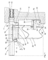
- den Mündungsbereich eines erfindungsgemässen Setzgerätes in teilweiser Schnittansicht, mit einem Magazin für Befestigungselemente,
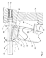
- Fig. 2
- den Mündungsbereich des Setzgerätes aus
Fig. 1 , mit dem Magazin in einer teilweise vom Gehäuse des Setzgerätes gelösten Position, - Fig. 3
- den Mündungsbereich des Setzgerätes aus
Fig. 1 , mit dem Magazin in einer vom Mündungsteil und vom Gehäuse des Setzgerätes gelösten Position.
- Fig. 1
- the mouth region of a setting device according to the invention in a partial sectional view, with a magazine for fastening elements,
- Fig. 2
- the mouth area of the setting device
Fig. 1 , with the magazine in a partially detached from the housing of the setting device position, - Fig. 3
- the mouth area of the setting device
Fig. 1 , with the magazine in a position detached from the mouth part and from the housing of the setting device.
In den
Koaxial zu der Führung 12 verlaufend ist eine, an einem Mündungsteil 14 angeordnete Bolzenführung 15 an dem Setzgerät 10 angeordnet, die mit ihrem dem Gehäuse 11 abgewandten freien Ende an ein Werkstück ansetzbar ist. Die Bolzenführung 15 dient dabei der Aufnahme und Führung von Befestigungselementen 50 (angedeutet in
Seitlich abragend von dem Mündungsteil 14 ist ein insgesamt mit 20 bezeichnetes Magazin an dem Setzgerät 10 über Verbindungsmittel lösbar angeordnet. In dem Magazin 20 ist ein Führungskanal 24 für Befestigungselemente 50 angeordnet, der zur Bolzenführung 15 hin geöffnet ist, so dass in der aus
Die erste Schmalseite 25 des Verbindungsabschnitts 21 und des Magazins 20 mit der konkaven Lagerfläche 22 ist einer zweiten Schmalseite 26 des Verbindungsabschnitts 21 und des Magazins 20 gegenüberliegend angeordnet. An der zweiten Schmalseite 26 ist im Bereich des Verbindungsabschnitts 21 ein Anschlag A angeordnet, der im am Setzgerät 10 festgelegten Zustand des Magazins 20 an einer Kante des Mündungsteils 14 anliegt und über den das Magazin 20 in einer der Eintreibrichtung des Treibkörpers 13 gegenüberliegenden Richtung gegenüber dem Mündungsteil 14 abgestützt ist. An der zweiten Schmalseite 26 im Bereich des eigentlichen Magazinkörpers ist ferner ein Schieber 31 eines insgesamt mit 30 bezeichneten Rastverschlusses (als weiteres Verbindungsmittel) entlang der Längserstreckung des Magazins 20 begrenzt verschieblich angeordnet. Der Schieber 31 ist dabei über wenigstens ein elastisches Element 32, wie z. B. ein Federelement, in eine Schieberichtung weg vom Verbindungsabschnitt 21 des Magazins 20 elastisch beaufschlagt. Der Schieber 31 weist an seinem dem Verbindungsabschnitt 21 abgewandten Endbereich wenigstens ein Rastglied 33 auf, das mit einem Gegenrastelement 34 des Rastverschlusses 30 am Gehäuse 11 in eine aus
The first
Zum Abnehmen des Magazins 20 von dem Mündungsteil 14 wird der Schieber 31 entgegen der Kraft des wenigstens einen elastischen Elements 32 manuell in Richtung des Pfeils 70 in eine Entriegelungsstellung 36 versetzt, wie in
Claims (6)
und mit einem über Verbindungsmittel lösbar an dem Mündungsteil (14) festlegbaren Magazin (20) für Befestigungselemente, das mit einem Verbindungsabschnitt (21) an seinem dem Mündungsteil (14) zugewandten Ende am Mündungsteil (14) ansetzbar ist,
wobei die Verbindungsmittel zwischen dem Mündungsteil (14) und dem Magazin (20) ein Schwenklager (17) mit einem ersten Lagermittel am Verbindungsabschnitt (21) des Magazins (20) und einem zweiten Lagermittel am Mündungsteil (14) beinhalten,
dadurch gekennzeichnet,
dass das Schwenklager (17) als Steckkupplung ausgebildet ist, wobei eine Schwenklagerachse (S) des Schwenklagers (17) an der dem Gehäuse (11) abgewandten Seite des Magazins (20), ausserhalb des Mündungsteils (14) und ausserhalb des Magazins (20) sowie in einem rechten Winkel zu einer durch die Bolzenführung (15) und das Magazin (20) definierten Ebene (E) liegt.Setting device, for driving in fastening elements, comprising a housing (11), with a driving body (13) displaceably guided in a guide (12), with a bolt guide (15) arranged in a mouth part (14),
and with a fastener magazine (20) releasably attachable to the mouth part (14), which can be attached to the mouth part (14) with a connecting portion (21) at its end facing the mouth part (14),
the connecting means between the mouth part (14) and the magazine (20) comprising a pivot bearing (17) with a first bearing means on the connecting portion (21) of the magazine (20) and a second bearing means on the mouth part (14),
characterized,
that the pivot bearing (17) is designed as a plug-in coupling, wherein a pivot bearing axis (S) of the pivot bearing (17) on the side facing away from the housing (11) of the magazine (20), outside the mouth part (14) and outside the magazine (20) and at a right angle to a through the bolt guide (15) and the magazine (20) defined plane (E).
Applications Claiming Priority (1)
| Application Number | Priority Date | Filing Date | Title |
|---|---|---|---|
| DE102008000835A DE102008000835A1 (en) | 2008-03-26 | 2008-03-26 | setting tool |
Publications (3)
| Publication Number | Publication Date |
|---|---|
| EP2105258A2 true EP2105258A2 (en) | 2009-09-30 |
| EP2105258A3 EP2105258A3 (en) | 2010-01-27 |
| EP2105258B1 EP2105258B1 (en) | 2012-04-25 |
Family
ID=40848188
Family Applications (1)
| Application Number | Title | Priority Date | Filing Date |
|---|---|---|---|
| EP09154067A Active EP2105258B1 (en) | 2008-03-26 | 2009-03-02 | Setting device |
Country Status (5)
| Country | Link |
|---|---|
| US (1) | US7980441B2 (en) |
| EP (1) | EP2105258B1 (en) |
| JP (1) | JP5457697B2 (en) |
| DE (1) | DE102008000835A1 (en) |
| ES (1) | ES2382763T3 (en) |
Cited By (4)
| Publication number | Priority date | Publication date | Assignee | Title |
|---|---|---|---|---|
| DE202015003581U1 (en) | 2015-05-20 | 2015-07-06 | Olaf Kersten | Gas operated setting tool |
| US10987790B2 (en) | 2016-06-30 | 2021-04-27 | Black & Decker Inc. | Cordless concrete nailer with improved power take-off mechanism |
| US11267114B2 (en) | 2016-06-29 | 2022-03-08 | Black & Decker, Inc. | Single-motion magazine retention for fastening tools |
| US11325235B2 (en) | 2016-06-28 | 2022-05-10 | Black & Decker, Inc. | Push-on support member for fastening tools |
Families Citing this family (10)
| Publication number | Priority date | Publication date | Assignee | Title |
|---|---|---|---|---|
| TWI434754B (en) * | 2007-08-17 | 2014-04-21 | Rexon Ind Corp Ltd | Nailer rotation device |
| JP5402868B2 (en) * | 2010-07-28 | 2014-01-29 | マックス株式会社 | Driving tool |
| DE202011003583U1 (en) | 2011-02-28 | 2012-05-29 | Chiron-Werke Gmbh & Co. Kg | Machine tool, in particular for wheel machining |
| DE102012209416A1 (en) * | 2012-06-04 | 2013-12-05 | Hilti Aktiengesellschaft | Magazine attachment and fastening system |
| CN105215940A (en) * | 2015-11-10 | 2016-01-06 | 四川德阳市力协有限责任公司 | The fast assembling disassembling structure of nail-shooting gun nail case |
| US11400572B2 (en) | 2016-06-30 | 2022-08-02 | Black & Decker, Inc. | Dry-fire bypass for a fastening tool |
| US11279013B2 (en) | 2016-06-30 | 2022-03-22 | Black & Decker, Inc. | Driver rebound plate for a fastening tool |
| US10926385B2 (en) | 2017-02-24 | 2021-02-23 | Black & Decker, Inc. | Contact trip having magnetic filter |
| US11110577B2 (en) | 2017-11-16 | 2021-09-07 | Milwaukee Electric Tool Corporation | Pneumatic fastener driver |
| WO2021168775A1 (en) * | 2020-02-28 | 2021-09-02 | 杭州巨星科技股份有限公司 | Staple box component, staple gun, and method for replacing staple box component of staple gun |
Citations (2)
| Publication number | Priority date | Publication date | Assignee | Title |
|---|---|---|---|---|
| DE3337278A1 (en) | 1983-10-13 | 1985-04-25 | Metabowerke GmbH & Co, 7440 Nürtingen | Driving-in machine |
| US6880739B1 (en) | 2003-12-18 | 2005-04-19 | Yimin Zhu | Powered nail-driving tool with an angle-adjustable nail magazine |
Family Cites Families (6)
| Publication number | Priority date | Publication date | Assignee | Title |
|---|---|---|---|---|
| DE2238105C3 (en) * | 1972-08-02 | 1981-02-05 | Hilti Ag, Schaan (Liechtenstein) | Feed device for fasteners, bolts, nails or the like. on a powder-operated bolt-firing device of the power piston type |
| US3840165A (en) * | 1973-08-15 | 1974-10-08 | Signode Corp | Magazine release mechanism for fastener driving tool |
| US4597517A (en) * | 1985-06-21 | 1986-07-01 | Signode Corporation | Magazine interlock for a fastener driving device |
| JP2002154068A (en) * | 2000-11-17 | 2002-05-28 | Kanematsu Nnk Corp | Magazine for fixture driving machine |
| US20060102683A1 (en) * | 2002-09-18 | 2006-05-18 | Schnell John W | Adjustable angle magazine with pick-off pivot assembly |
| JP2006007343A (en) * | 2004-06-23 | 2006-01-12 | Max Co Ltd | Body protector for fastener driving tool |
-
2008
- 2008-03-26 DE DE102008000835A patent/DE102008000835A1/en not_active Withdrawn
-
2009
- 2009-03-02 ES ES09154067T patent/ES2382763T3/en active Active
- 2009-03-02 EP EP09154067A patent/EP2105258B1/en active Active
- 2009-03-18 JP JP2009066323A patent/JP5457697B2/en active Active
- 2009-03-25 US US12/383,786 patent/US7980441B2/en active Active
Patent Citations (2)
| Publication number | Priority date | Publication date | Assignee | Title |
|---|---|---|---|---|
| DE3337278A1 (en) | 1983-10-13 | 1985-04-25 | Metabowerke GmbH & Co, 7440 Nürtingen | Driving-in machine |
| US6880739B1 (en) | 2003-12-18 | 2005-04-19 | Yimin Zhu | Powered nail-driving tool with an angle-adjustable nail magazine |
Cited By (4)
| Publication number | Priority date | Publication date | Assignee | Title |
|---|---|---|---|---|
| DE202015003581U1 (en) | 2015-05-20 | 2015-07-06 | Olaf Kersten | Gas operated setting tool |
| US11325235B2 (en) | 2016-06-28 | 2022-05-10 | Black & Decker, Inc. | Push-on support member for fastening tools |
| US11267114B2 (en) | 2016-06-29 | 2022-03-08 | Black & Decker, Inc. | Single-motion magazine retention for fastening tools |
| US10987790B2 (en) | 2016-06-30 | 2021-04-27 | Black & Decker Inc. | Cordless concrete nailer with improved power take-off mechanism |
Also Published As
| Publication number | Publication date |
|---|---|
| EP2105258B1 (en) | 2012-04-25 |
| JP5457697B2 (en) | 2014-04-02 |
| EP2105258A3 (en) | 2010-01-27 |
| DE102008000835A1 (en) | 2009-10-01 |
| ES2382763T3 (en) | 2012-06-13 |
| JP2009233847A (en) | 2009-10-15 |
| US20090242608A1 (en) | 2009-10-01 |
| US7980441B2 (en) | 2011-07-19 |
Similar Documents
| Publication | Publication Date | Title |
|---|---|---|
| EP2105258B1 (en) | Setting device | |
| EP2105259B1 (en) | Setting device | |
| EP0091403B1 (en) | Tourniquet | |
| DE69829512T2 (en) | Pneumatic nail machine for fine work | |
| DE102005044128B4 (en) | hand tool | |
| DE68909709T2 (en) | Tool for tensioning straps for cables. | |
| DE19508035C2 (en) | Power tool with removable additional handle | |
| DE102010040780A1 (en) | Fixing device for fastening means with a Leerabschussverriegelungsvorrichtung | |
| CH691444A5 (en) | Hand tool with a battery backed drive motor. | |
| DE3436020A1 (en) | SUPPLIED FASTENER SETTING MACHINE (TACKER) WITH SAFETY DEVICE | |
| EP0132593A2 (en) | Auxiliary handle for hand tools | |
| EP2059761A1 (en) | Attachment element for a pistol grip | |
| DE2809791C2 (en) | Device for bundling several objects, in particular electrical cables, with a tightening strap | |
| DE3105951A1 (en) | "POWER TOOL" | |
| DE3038565C2 (en) | Stapler | |
| EP1232796A1 (en) | Self-cleaning spray gun nozzle | |
| DE202010013179U1 (en) | Electric hammer | |
| DE102004061522A1 (en) | Side handle | |
| EP2468460A2 (en) | Additional handle, hand-held machine tool, system | |
| DE8811528U1 (en) | Locking device | |
| DE1628027B2 (en) | Device for locking the magazine interest on a handheld device for driving in fasteners | |
| DE102021126490B3 (en) | Handle with an ejector for a wet razor | |
| EP1466690A1 (en) | Saber saw with adjusting device for a guide | |
| DE3629111A1 (en) | TAPER TYPE STAPLER | |
| DE2629446C3 (en) | Operating device for a portable power tool |
Legal Events
| Date | Code | Title | Description |
|---|---|---|---|
| PUAI | Public reference made under article 153(3) epc to a published international application that has entered the european phase |
Free format text: ORIGINAL CODE: 0009012 |
|
| AK | Designated contracting states |
Kind code of ref document: A2 Designated state(s): AT BE BG CH CY CZ DE DK EE ES FI FR GB GR HR HU IE IS IT LI LT LU LV MC MK MT NL NO PL PT RO SE SI SK TR |
|
| AX | Request for extension of the european patent |
Extension state: AL BA RS |
|
| PUAL | Search report despatched |
Free format text: ORIGINAL CODE: 0009013 |
|
| AK | Designated contracting states |
Kind code of ref document: A3 Designated state(s): AT BE BG CH CY CZ DE DK EE ES FI FR GB GR HR HU IE IS IT LI LT LU LV MC MK MT NL NO PL PT RO SE SI SK TR |
|
| AX | Request for extension of the european patent |
Extension state: AL BA RS |
|
| 17P | Request for examination filed |
Effective date: 20100727 |
|
| AKX | Designation fees paid |
Designated state(s): DE ES FR GB IT |
|
| GRAP | Despatch of communication of intention to grant a patent |
Free format text: ORIGINAL CODE: EPIDOSNIGR1 |
|
| GRAS | Grant fee paid |
Free format text: ORIGINAL CODE: EPIDOSNIGR3 |
|
| GRAA | (expected) grant |
Free format text: ORIGINAL CODE: 0009210 |
|
| AK | Designated contracting states |
Kind code of ref document: B1 Designated state(s): DE ES FR GB IT |
|
| REG | Reference to a national code |
Ref country code: GB Ref legal event code: FG4D Free format text: NOT ENGLISH |
|
| REG | Reference to a national code |
Ref country code: ES Ref legal event code: FG2A Ref document number: 2382763 Country of ref document: ES Kind code of ref document: T3 Effective date: 20120613 |
|
| REG | Reference to a national code |
Ref country code: DE Ref legal event code: R096 Ref document number: 502009003333 Country of ref document: DE Effective date: 20120614 |
|
| PLBE | No opposition filed within time limit |
Free format text: ORIGINAL CODE: 0009261 |
|
| STAA | Information on the status of an ep patent application or granted ep patent |
Free format text: STATUS: NO OPPOSITION FILED WITHIN TIME LIMIT |
|
| 26N | No opposition filed |
Effective date: 20130128 |
|
| REG | Reference to a national code |
Ref country code: DE Ref legal event code: R097 Ref document number: 502009003333 Country of ref document: DE Effective date: 20130128 |
|
| REG | Reference to a national code |
Ref country code: FR Ref legal event code: PLFP Year of fee payment: 8 |
|
| REG | Reference to a national code |
Ref country code: FR Ref legal event code: PLFP Year of fee payment: 9 |
|
| REG | Reference to a national code |
Ref country code: FR Ref legal event code: PLFP Year of fee payment: 10 |
|
| PGFP | Annual fee paid to national office [announced via postgrant information from national office to epo] |
Ref country code: DE Payment date: 20240320 Year of fee payment: 16 Ref country code: GB Payment date: 20240320 Year of fee payment: 16 |
|
| PGFP | Annual fee paid to national office [announced via postgrant information from national office to epo] |
Ref country code: IT Payment date: 20240329 Year of fee payment: 16 Ref country code: FR Payment date: 20240322 Year of fee payment: 16 |
|
| PGFP | Annual fee paid to national office [announced via postgrant information from national office to epo] |
Ref country code: ES Payment date: 20240426 Year of fee payment: 16 |