EP2104976B1 - Electrical machine - Google Patents
Electrical machine Download PDFInfo
- Publication number
- EP2104976B1 EP2104976B1 EP07822518A EP07822518A EP2104976B1 EP 2104976 B1 EP2104976 B1 EP 2104976B1 EP 07822518 A EP07822518 A EP 07822518A EP 07822518 A EP07822518 A EP 07822518A EP 2104976 B1 EP2104976 B1 EP 2104976B1
- Authority
- EP
- European Patent Office
- Prior art keywords
- rotor
- electrical machine
- stator
- magnetic
- machine according
- Prior art date
- Legal status (The legal status is an assumption and is not a legal conclusion. Google has not performed a legal analysis and makes no representation as to the accuracy of the status listed.)
- Not-in-force
Links
Images


Classifications
-
- H—ELECTRICITY
- H02—GENERATION; CONVERSION OR DISTRIBUTION OF ELECTRIC POWER
- H02K—DYNAMO-ELECTRIC MACHINES
- H02K21/00—Synchronous motors having permanent magnets; Synchronous generators having permanent magnets
- H02K21/38—Synchronous motors having permanent magnets; Synchronous generators having permanent magnets with rotating flux distributors, and armatures and magnets both stationary
- H02K21/44—Synchronous motors having permanent magnets; Synchronous generators having permanent magnets with rotating flux distributors, and armatures and magnets both stationary with armature windings wound upon the magnets
Definitions
- the present invention relates to an electric machine according to the preamble of patent claim 1 and a pump according to claim 15.
- the invention includes a rotor, a stator, a rotating field generating device and a pole field generating device, wherein the rotor is rotatable about an axis of rotation which passes through two opposite portions of the rotor, and wherein the rotary field generating means is adapted to generate a substantially radial magnetic field rotates about the axis of rotation of the rotor, and wherein the pole field generating means is adapted to generate a magnetic field, which poles the rotor opposite to the opposite portions.
- the pole field generating device is designed as a coil, which is integrated in the stator.
- Such electrical machines can rotate faster than machines having a commutator, and thus can according to the US 2006/0057004 A1 for example, be used to actuate a pump that pumps a smaller volume per pump cycle than another pump and therefore can be made smaller than the other pump, but has the same pumping power, since it can be operated at a higher frequency.
- Such electrical machines are therefore also considered as a compressor drive for fuel cells to save space and weight.
- One Disadvantage is that the electrical machine allows the space-saving design of a pump, but takes up much space itself
- the present invention is based on the delivery of an electric machine and a pump, for which the machine is used, without reducing performance.
- the object underlying the invention is achieved by an electrical machine having the features of the characterizing part of patent claim 1 and a pump for an electrical machine with the features of claim 15.
- the invention relates to an electrical machine having a rotor, a stator, a rotary field generating device and a pole field generating device, wherein the rotor is rotatable about an axis of rotation which passes through two opposite sections of the rotor.
- the rotary field generating device is configured to generate a substantially radial magnetic field which rotates about the axis of rotation of the rotor.
- the pole field generating device comprises at least one magnet and is adapted to generate a magnetic field which poles the rotor in opposite directions at the opposite sections.
- opposing outer surfaces of the first portion are rotated 90 degrees relative to opposite outer surfaces of the second portion such that magnetic poles on the second portion are offset from magnetic poles on the first portion by 90 degrees, the magnetic poles (N, S) of the first and the second portion (5, 6) have an opposite polarity.
- energy is saved because no current is required to generate the magnetic field which poles the rotor in opposite directions at the opposite portions.
- the stator comprises two stator elements which are arranged along the axis of rotation.
- the space which must be present between the two stator elements can be used to accommodate the magnet. Heat can be dissipated by the magnet easily to the two stator elements of the stator.
- the magnet is protected from opposing fields by the two stator elements, so that demagnetization can be prevented.
- a housing is provided which is not magnetic.
- a magnetic short circuit through the housing can be avoided.
- the at least one magnet is designed as a wood cylinder, which surrounds one of the two stator elements, wherein a further designed as a wood cylinder magnet surrounds the other of the two stator elements.
- heat from the magnets can be easily dissipated to the stator elements.
- the magnets are protected from opposing fields by the stator elements, so that demagnetization can be prevented. Due to the large contact area between the stator elements and the magnets, inexpensive ferrite magnets can generate a sufficient magnetic field.
- a housing is provided which is magnetic.
- the magnetic resistance can be reduced by the fact that the magnetic field lines run almost completely through a magnetic material.
- the at least one magnet is cuboid-shaped and arranged outside on one of the two stator elements.
- heat from the magnets can be easily dissipated to the stator elements.
- the magnets are protected from opposing fields by the stator elements, so that demagnetization can be prevented.
- a cuboid shape can also be made easily and therefore inexpensively. Tolerances between stator elements and the magnets are also of little importance.
- the pole field generating device also comprises further parallelepipedic magnets, which are provided on the outside of the stator elements.
- a magnetic field symmetrical to the axis of rotation can be generated by a plurality of parallelepipedic magnets.
- a housing is provided which is magnetic.
- the magnetic resistance can be reduced by the fact that the magnetic field lines run almost completely through a magnetic material.
- each stator element consists of a plurality of annular parts.
- the dimensions of the stator elements can be reduced to such an extent with high performance of the machine that they can be manufactured by pressing soft magnetic material in sufficient quality.
- the stator is made of a soft magnetic composite material.
- eddy current losses in the stator can be reduced.
- Such a stator also has approximately identical magnetic properties in all directions. Compared to laminated stators, the magnetic resistance in the axial direction transverse to the lamellae is also significantly smaller, which leads to an improvement in performance.
- the dimensions of the stator elements can be reduced to such an extent with high performance of the machine that they can be manufactured by pressing soft magnetic material in sufficient quality.
- the electric machine comprises a further rotor, a further stator, a further rotary field generating device, and a further pole field generating device, wherein the further rotor is rotatable about the axis of rotation which is defined by two further opposite sections of the further rotor passes, wherein the further Polfelder Wegungs adopted is adapted to generate a further magnetic field, which poles the other rotor opposite to the other opposite sections, and wherein the further Polfelder Wegungs worn comprises at least one magnet.
- the electric machine can be used both as an electric motor and as a generator for the delivery of electrical energy.
- FIG. 1A shows a view of an electric machine with a magnet between two identical stator elements of a stator 1 perpendicular to the axis of rotation of a rotor 4.
- the two stator elements are arranged one above the other along the axis of rotation.
- the upper 7 of the two stator elements obscures the lower of the two stator elements and the magnet which acts as a pole field generator.
- the housing is not shown.
- the stator elements for this and the other embodiments consist of a soft magnetic material, preferably a soft magnetic composite (SMC) such as pressed oxidized iron powder, to suppress eddy currents.
- SMC soft magnetic composite
- the stator elements can be pressed directly into the mold or shaped by electric discharge after pressing.
- the stator elements have a hollow cylindrical shape, protruding at their inner peripheries 12 projections 2 radially inwardly. In each case 3 superimposed projections 2 of the two stator elements (ie a total of 6 projections), a coil 3 is wound. Overall, for the sake of simplicity, 4 Coils are shown which serve to generate a magnetic field which rotates about the axis of rotation of the rotor 4. Usual are 12 coils, each wound around one of the 12 projections by 3 projections, so that each projection is surrounded by 3 coils.
- the rotor 4 is also made of a soft magnetic material, is rotatably mounted inside the stator 1 and comprises along its axis of rotation an upper portion 5 and a lower portion 6.
- Each section 5, 6 comprises two opposite circular outer surfaces, each close to the inside protruding projections 2 of the upper stator 7 and the lower stator, so that only a narrow gap between these projections 2 and the opposite portions 5, 6 is formed. Between the two opposite round outer surfaces of each section 5, 6 are each formed two opposite planar parallel outer surfaces. The opposite outer surfaces of the portion 6 are rotated 90 degrees relative to the opposite outer surfaces of the portion 5.
- a machine having any other number of poles and protrusions may be used as known in the art.
- FIG. 1B shows a sectional view of the electric machine FIG. 1A along its axis of rotation.
- the corresponding cutting line is in FIG. 1A shown as line 1B-1B.
- the coils 3 are not shown.
- an annular magnet 9 is arranged, which generates a magnetic field, which poles the rotor 4 at the upper section 5 and the lower section 6 in opposite directions.
- the magnet 9 may be composed of a plurality of partial magnets, for example two semi-annular magnetic shells. On the magnet 9 and projections may be formed, which are formed between the projections 2 of the two stator elements.
- an upper journal 10 and a lower journal 11 are integrally formed with the rotor 4.
- the axle journal 10, 11 are mounted in an upper and lower housing cover 12, 13, which are secured to the opposite ends of a cylindrical housing 14.
- the housing 14 is not magnetic to prevent a magnetic short circuit through the housing 14.
- In the middle of the upper and lower housing cover 12, 13 is in each case an upper or lower end cap 15, 16, which covers a bearing.
- One or both journals 10, 11 may also pass into a shaft (not shown) provided outside the housing 14 to transmit the torque of the machine to a pump in a known manner.
- the pump is used, for example, in a turbine of a compressor drive for a fuel cell.
- the upper portion 5 is shown along its large cross section from a rounded outer surface to the opposite rounded outer surface, while the lower portion 6 is shown along its small cross section from a flat outer surface to the opposite outer surface.
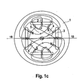
- FIG. 1C shows a further view of the electric machine FIG. 1A and the field line course of the magnetic field generated by the magnet 9.
- the rotor 4 is, however, opposite to the position FIG. 1A shown in a rotated position. Only the component of the magnetic field perpendicular to the axis of rotation of the rotor 4 is shown.
- the magnetic field lines enter via the inwardly projecting projections 2 of the stator 1 in the lower portion 5 of the rotor 4, so that at the lower portion 6 of the rotor 4, two opposite magnetic poles S are formed.
- the magnetic field lines re-enter via two opposite ends of the upper portion 5 in the inwardly projecting projections 2 of the stator 1, so that at the upper end of the rotor 4, two opposite magnetic poles N are formed.
- the magnetic flux passes almost exclusively through the projections 2, which are adjacent to the stator 4. Due to the structure of the rotor 4, the magnetic poles S at the lower portion 6 of the rotor 4 are offset from the magnetic poles N at the upper portion 5 of the rotor 4 by 90 degrees. By applying a current of suitable direction, magnetic poles N and S can be alternately formed on the inwardly facing sides of the coils 2, which are arranged so as to attract and repel the magnetic poles N, S of the rotor in the clockwise direction.
- FIG. 3A, 3B differ from the electric machine FIG. 1A and FIG. 1B by the magnet or magnets which generate the magnetic field for the purpose of poling the rotor.
- identical reference numerals are used for identical elements, and identical reference numerals are used for modified elements, which are provided with one, two or three strokes.
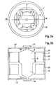
- FIG. 2A shows a view of an electric machine with hollow cylindrical magnets 24, 25 (hidden), which generate the magnetic field to the poles of the rotor 4.
- the magnets 24, 25 may also be composed of a plurality of partial magnets, such as two half rings.
- FIG. 2 B shows a sectional view of the electric machine FIG. 2A along its axis of rotation. The corresponding cutting line is in FIG. 2A shown as line 2B-2B.
- the coils 3 are not shown.
- the stator 1 ' consists of two annular stator elements 7', 8 ', which are respectively surrounded by the magnet 24 and 25 respectively.
- the magnets 24, 25 are radially and oppositely poled.
- the housing 14 ' is made of a magnetic material to reduce the magnetic resistance by forming a magnetic bridge through the housing 14'. It is possible to use only one of the magnets 24, 25 and to dispense with the other magnet.
- FIG. 3A shows a view of an electric machine with a plurality of magnets 26, 27 (hidden), which generate the magnetic field to the poles of the rotor 4.
- the magnets 26, 27 are cuboid.
- the locations of the otherwise externally round stator elements of the stator 1 ", where the magnets 26, 27 abut against the stator elements of the stator 1", are flattened to allow good contact between the stator 1 '' and the magnets 26, 27.
- the number of magnets 26, 27 is arbitrary. However, the magnets 26, 27 should be symmetrically arranged to produce a corresponding symmetrical magnetic field.
- FIG. 3B shows sectional view of the electric machine FIG. 3A along its axis of rotation.
- the stator 1 consists of two annular stator elements 7", 8 ", each surrounded by a plurality of magnets 26, 27.
- the magnets 26, 27 are radially poled, and the magnets 26 are polarized opposite to the magnets 27. Between the two An air gap is formed on the annular stator elements 7 “, 8” to avoid a magnetic short circuit between the stator elements 7 ", 8".
- the housing 14 is made of a magnetic material to provide the magnetic resistance by forming a magnetic bridge through the housing 14 It is possible to use only one of the magnets 26, 27 and to dispense with the other magnet.
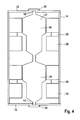
- FIG. 4 shows a sectional view of a double electrical machine along its axis of rotation.
- the double rotor 17 is made of two rotors 18 and 19, which are integrally formed and each have the same structure as the rotor 4 of the preceding figures.
- the two rotors 18, 19 are connected together so that the interconnected portions are aligned identically and a stator member 20 can be used to poler both interconnected portions.
- the stator comprises two further stator elements 21 which are separated from the stator element 20 by respective magnets 22 and 23, respectively.
- stators and magnets can be used, which are made of FIG. 2A, 2B and 3A, 3B are known, wherein two adjacent stator elements as in FIG. 4 are integrally formed.
- FIG. 5 shows a sectional view of an electric machine, wherein each stator 8 '' consists of a plurality of annular parts 28.
- the in the FIGS. 1 to 5 shown electrical machines can be used both as a motor and as a generator for generating electrical energy.
Landscapes
- Engineering & Computer Science (AREA)
- Power Engineering (AREA)
- Permanent Magnet Type Synchronous Machine (AREA)
- Permanent Field Magnets Of Synchronous Machinery (AREA)
- Dc Machiner (AREA)
- Reciprocating, Oscillating Or Vibrating Motors (AREA)
- Iron Core Of Rotating Electric Machines (AREA)
- Devices For Conveying Motion By Means Of Endless Flexible Members (AREA)
- Brushless Motors (AREA)
Abstract
Description
Die vorliegende Erfindung betrifft eine elektrische Maschine gemäß dem Oberbegriff des Patentanspruchs 1 und eine Pumpe nach Anspruch 15.The present invention relates to an electric machine according to the preamble of
Eine solche elektrische Maschine, die auch als synchrone Homopolar- oder Gleichpolmaschine bekannt und beispielsweise in der
Derartige elektrische Maschinen können sich schneller drehen als Maschinen, die einen Kommutator aufweisen, und können somit gemäß der
Derartige elektrische Maschinen werden daher auch als Verdichterantrieb für Brennstoffzellen in Erwägung gezogen, um Bauraum und Gewicht einzusparen. Ein Nachteil liegt darin, dass die elektrische Maschine zwar die platzsparende Ausbildung einer Pumpe ermöglicht, selbst aber viel Platz beanspruchtSuch electrical machines are therefore also considered as a compressor drive for fuel cells to save space and weight. One Disadvantage is that the electrical machine allows the space-saving design of a pump, but takes up much space itself
Der vorliegenden Erfindung liegt die Abgabe zugrunde, eine elektrische Maschine und-eine Pumpe, für welche die Maschine verwendet wird, ohne Leistungseinbußen zu verkleinern. Die der Erfindung zugrunde liegende Aufgabe wird durch eine elektrische Maschine mit den Merkmalen des kennzeichnenden Teils des Patentanspruchs 1 und eine Pumpe für eine elektrische Maschine mit den Merkmalen des Patentanspruchs 15 gelöst.The present invention is based on the delivery of an electric machine and a pump, for which the machine is used, without reducing performance. The object underlying the invention is achieved by an electrical machine having the features of the characterizing part of
Die Erfindung betrifft eine elektrische Maschine mit einem Rotor, einem Stator, einer Drehfelderzeugungseinrichtung und einer Polfelderzeugungseinrichtung, wobei der Rotor um eine Drehachse drehbar ist, die durch zwei gegenüberliegende Abschnitte des Rotors hindurchgeht. Die Drehfelderzeugungseinrichtung ist eingerichtet, ein im wesentlichen radiales Magnetfeld zu erzeugen, das sich um die Drehachse des Rotors dreht. Die Polfelderzeugungseinrichtung umfasst mindestens einen Magneten und ist eingerichtet, ein Magnetfeld zu erzeugen, welches den Rotor an den gegenüberliegenden Abschnitten entgegengesetzt polt. Erfindungsgemäß ist vorgesehen, dass gegenüberliegende Außenflächen des ersten Abschnitts relativ zu gegenüberliegenden Außenflächen des zweiten Abschnitts derart um 90 Grad gedreht sind, dass Magnetpole am zweiten Abschnitt gegenüber Magnetpolen am ersten Abschnitt um 90 Grad versetzt sind, wobei die Magnetpole (N, S) des ersten und des zweiten Abschnitts (5, 6) eine entgegengesetze Polarität aufweisen. Vorteilhafterweise wird Energie eingespart, da zur Erzeugung des Magnetfelds, welches den Rotor an den gegenüberliegenden Abschnitten entgegengesetzt polt, kein Strom erforderlich ist.The invention relates to an electrical machine having a rotor, a stator, a rotary field generating device and a pole field generating device, wherein the rotor is rotatable about an axis of rotation which passes through two opposite sections of the rotor. The rotary field generating device is configured to generate a substantially radial magnetic field which rotates about the axis of rotation of the rotor. The pole field generating device comprises at least one magnet and is adapted to generate a magnetic field which poles the rotor in opposite directions at the opposite sections. According to the invention, opposing outer surfaces of the first portion are rotated 90 degrees relative to opposite outer surfaces of the second portion such that magnetic poles on the second portion are offset from magnetic poles on the first portion by 90 degrees, the magnetic poles (N, S) of the first and the second portion (5, 6) have an opposite polarity. Advantageously, energy is saved because no current is required to generate the magnetic field which poles the rotor in opposite directions at the opposite portions.
In einer bevorzugten Ausführungsform sind die Außenflächen der beiden gegenüberliegenden Abschnitte aus jeweils zwei gegenüberliegenden, runden Außenflächen und jeweils zwei gegenüberliegenden, ebenen, parallelen Aüßenflächen gebildet. Weiterhin ist vorgesehen, dass der Stator zwei Statorelemente umfasst, die entlang der Drehachse angeordnet sind. Vorteilhafterweise kann der Raum, der zwischen den zwei Statorelementen vorhanden sein muss, genutzt werden, um den Magneten unterzubringen. Wärme kann von dem Magneten leicht zu den zwei Statorelementen des Stators abgeführt werden. Außerdem ist der Magnet vor Gegenfelder durch die zwei Statorelemente geschützt, so dass eine Entmagnetisierung verhindert werden kann. In einer Weiterbildung der bevorzugten Ausführungsform ist ein Gehäuse vorgesehen, das nicht magnetisch ist. Vorteilhafterweise kann ein magnetischer Kurzschluss durch das Gehäuse vermieden werden.In a preferred embodiment, the outer surfaces of the two opposite sections of each two opposite, round outer surfaces and two opposite, planar, parallel Assenflächen formed. It is further provided that the stator comprises two stator elements which are arranged along the axis of rotation. Advantageously, the space which must be present between the two stator elements can be used to accommodate the magnet. Heat can be dissipated by the magnet easily to the two stator elements of the stator. In addition, the magnet is protected from opposing fields by the two stator elements, so that demagnetization can be prevented. In a development of the preferred embodiment, a housing is provided which is not magnetic. Advantageously, a magnetic short circuit through the housing can be avoided.
In noch einer bevorzugten Ausführungsform ist der mindestens eine Magnet als Holzylinder ausgebildet, welcher eines der zwei Statorelemente umgibt, wobei ein weiterer als Holzylinder ausgebildeter Magnet das andere der zwei Statorelemente umgibt.In yet a preferred embodiment, the at least one magnet is designed as a wood cylinder, which surrounds one of the two stator elements, wherein a further designed as a wood cylinder magnet surrounds the other of the two stator elements.
Vorteilhafterweise kann Wärme von den Magneten leicht zu den Statorelementen abgeführt werden. Außerdem sind die Magnete vor Gegenfelder durch die Statorelemente geschützt, so dass eine Entmagnetisierung verhindert werden kann. Aufgrund der großen Berührungsfläche zwischen den Statorelementen und den Magneten können preisgünstige Ferritmagnete ein ausreichendes Magnetfeld erzeugen. In einer Weiterbildung der bevorzugten Ausführungsform ist ein Gehäuse vorgesehen, das magnetisch ist. Vorteilhafterweise kann der magnetische Widerstand dadurch verringert werden, dass die magnetischen Feldlinien fast vollkommen durch einen magnetischen Werkstoff verlaufen.Advantageously, heat from the magnets can be easily dissipated to the stator elements. In addition, the magnets are protected from opposing fields by the stator elements, so that demagnetization can be prevented. Due to the large contact area between the stator elements and the magnets, inexpensive ferrite magnets can generate a sufficient magnetic field. In a development of the preferred embodiment, a housing is provided which is magnetic. Advantageously, the magnetic resistance can be reduced by the fact that the magnetic field lines run almost completely through a magnetic material.
In noch einer bevorzugten Ausführungsform ist der mindestens eine Magnet quaderförmig ausgebildet und außen an einem der zwei Statorelemente angeordnet. Es ist ein weiterer quaderförmiger Magnet vorgesehen, der außen an dem anderen der zwei Statorelemente angeordnet ist. Vorteilhafterweise kann Wärme von den Magneten leicht zu den Statorelementen abgeführt werden. Außerdem sind die Magnete vor Gegenfelder durch die Statorelemente geschützt, so dass eine Entmagnetisierung verhindert werden kann. Eine quaderförmige Gestalt kann außerdem leicht und daher preisgünstig hergestellt werden. Toleranzen zwischen Statorelementen und den Magneten sind zudem kaum von Bedeutung.In yet a preferred embodiment, the at least one magnet is cuboid-shaped and arranged outside on one of the two stator elements. There is another parallelepiped magnet, which is arranged on the outside of the other of the two stator elements. Advantageously, heat from the magnets can be easily dissipated to the stator elements. In addition, the magnets are protected from opposing fields by the stator elements, so that demagnetization can be prevented. A cuboid shape can also be made easily and therefore inexpensively. Tolerances between stator elements and the magnets are also of little importance.
In einer Weiterbildung der bevorzugten Ausführungsform umfasst die Polfelderzeugungseinrichtung noch weitere quaderförmige Magnete, die außen an den Statorelementen vorgesehen sind. Vorteilhafterweise kann durch mehrere quaderförmige Magnete ein zu der Drehachse symmetrisches Magnetfeld erzeugt werden. In noch einer Weiterbildung der bevorzugten Ausführungsform ist ein Gehäuse vorgesehen, das magnetisch ist. Vorteilhafterweise kann der magnetische Widerstand dadurch verringert werden, dass die magnetischen Feldlinien fast vollkommen durch einen magnetischen Werkstoff verlaufen.In a further development of the preferred embodiment, the pole field generating device also comprises further parallelepipedic magnets, which are provided on the outside of the stator elements. Advantageously, a magnetic field symmetrical to the axis of rotation can be generated by a plurality of parallelepipedic magnets. In a further development of the preferred embodiment, a housing is provided which is magnetic. Advantageously, the magnetic resistance can be reduced by the fact that the magnetic field lines run almost completely through a magnetic material.
In einer Weiterbildung der bevorzugten Ausführungsformen besteht jedes Statorelemente aus mehreren ringförmigen Teilen. Vorteilhafterweise können die Abmessungen der Statorelemente bei hoher Leistungsfähigkeit der Maschine so weit verringert werden, dass diese durch Pressen von weichmagnetischem Material in ausreichender Qualität hergestellt werden können.In a development of the preferred embodiments, each stator element consists of a plurality of annular parts. Advantageously, the dimensions of the stator elements can be reduced to such an extent with high performance of the machine that they can be manufactured by pressing soft magnetic material in sufficient quality.
In noch einer bevorzugten Ausführungsform besteht der Stator aus einem weichmagnetischen Verbundwerkstoff. Vorteilhafterweise können Wirbelstromverluste im Stator verringert werden. Ein solcher Stator weist außerdem in allen Richtungen annährend identische magnetische Eigenschaften auf. Gegenüber lamellierten Statoren ist der magnetische Widerstand in axialer Richtung quer zu den Lamellen zudem deutlich kleiner, was zu einer Verbesserung der Leistungsfähigkeit führt.In yet a preferred embodiment, the stator is made of a soft magnetic composite material. Advantageously, eddy current losses in the stator can be reduced. Such a stator also has approximately identical magnetic properties in all directions. Compared to laminated stators, the magnetic resistance in the axial direction transverse to the lamellae is also significantly smaller, which leads to an improvement in performance.
Vorteilhafterweise können die Abmessungen der Statorelemente bei hoher Leistungsfähigkeit der Maschine so weit verringert werden, dass diese durch Pressen von weichmagnetischem Material in ausreichender Qualität hergestellt werden können.Advantageously, the dimensions of the stator elements can be reduced to such an extent with high performance of the machine that they can be manufactured by pressing soft magnetic material in sufficient quality.
In noch einer bevorzugten Ausführungsform umfasst die elektrische Maschine einen weiteren Rotor, einen weiteren Stator, eine weitere Drehfelderzeugungseinrichtung, und eine weitere Polfelderzeugungseinrichtung, wobei der weitere Rotor um die Drehachse drehbar ist, die durch zwei weitere gegenüberliegende Abschnitte des weiteren Rotors hindurchgeht, wobei die weitere Polfelderzeugungseinrichtung eingerichtet ist, ein weiteres Magnetfeld zu erzeugen, welches den weiteren Rotor an den weiteren gegenüberliegenden Abschnitten entgegengesetzt polt, und wobei die weitere Polfelderzeugungseinrichtung mindestens einen Magnet umfasst.In a further preferred embodiment, the electric machine comprises a further rotor, a further stator, a further rotary field generating device, and a further pole field generating device, wherein the further rotor is rotatable about the axis of rotation which is defined by two further opposite sections of the further rotor passes, wherein the further Polfelderzeugungseinrichtung is adapted to generate a further magnetic field, which poles the other rotor opposite to the other opposite sections, and wherein the further Polfelderzeugungseinrichtung comprises at least one magnet.
Die elektrische Maschine kann sowohl als elektrischer Motor als auch als Generator zur Abgabe elektrischer Energie verwendet werden.The electric machine can be used both as an electric motor and as a generator for the delivery of electrical energy.
Im folgenden wird die Erfindung mit Bezugnahme auf die Zeichnungen näher beschrieben. Es zeigen:
-
FIG. 1A eine Ansicht einer elektrischen Maschine mit einem Magneten zwischen zwei Statorelementen eines Stators; -
FIG. 1B eine Schnittansicht der elektrischen Maschine ausFIG. 1A entlang dessen Drehachse; -
FIG. 1C eine weitere Ansicht der elektrischen Maschine ausFIG. 1A und den Feldlinienverlauf des durch eine Polfelderzeugungseinrichtung erzeugten Magnetfelds; -
FIG. 2A eine Ansicht einer elektrischen Maschine mit hohlzylindrischen Magneten, welche den Stator umgeben; -
FIG. 2B eine Schnittansicht der elektrischen Maschine ausFIG. 2A entlang dessen Drehachse; -
FIG. 3A eine Ansicht einer elektrischen Maschine mit mehreren Magneten, welche den Stator umgeben; -
FIG. 3B eine Schnittansicht der elektrischen Maschine ausFIG. 3A entlang dessen Drehachse; -
FIG. 4 eine Schnittansicht einer elektrischen Doppelmaschine entlang dessen Drehachse; und -
FIG. 5 eine Schnittansicht einer elektrischen Maschine, wobei jedes Statorelement aus mehreren Teilen besteht.
-
FIG. 1A a view of an electric machine with a magnet between two stator elements of a stator; -
FIG. 1B a sectional view of the electric machineFIG. 1A along its axis of rotation; -
FIG. 1C another view of the electric machineFIG. 1A and the field line shape of the magnetic field generated by a pole field generating means; -
FIG. 2A a view of an electric machine with hollow cylindrical magnets surrounding the stator; -
FIG. 2 B a sectional view of the electric machineFIG. 2A along its axis of rotation; -
FIG. 3A a view of an electric machine with a plurality of magnets surrounding the stator; -
FIG. 3B a sectional view of the electric machineFIG. 3A along its axis of rotation; -
FIG. 4 a sectional view of a double electric machine along the axis of rotation thereof; and -
FIG. 5 a sectional view of an electrical machine, wherein each stator consists of several parts.
Die folgenden elektrischen Maschinen aus
Die in den
Claims (15)
- Electrical machine having a rotor (4), having a stator (1, 1', 1", 20) having a rotating-field production device (3) and having a pole-field production device (9, 22, 24, 25, 26, 27) wherein the rotor (4, 18) can rotate about a rotation axis which passes through two opposite sections (5, 6) of the rotor (4, 18), wherein the rotating-field production device (3) is designed to produce a substantially radial magnetic field which rotates about the rotation axis of the rotor (4), wherein the pole-field production device (9, 22, 24, 25, 26, 27) comprises at least one magnet (9, 22, 24, 25, 26, 27) and is designed to produce a magnetic field of opposite polarity to the rotor (4) on the opposite sections (5, 6), characterized in that opposite outer surfaces of the first section (5) are rotated through 90 degrees relative to opposite outer surfaces of the second section (6), such that magnetic poles (S) on the second section (6) are offset through 90 degrees with respect to magnetic poles (N) on the first section (5), wherein the magnetic poles (N) on the first section (5) are of opposite polarity to the magnetic poles (S) on the second section (6).
- Electrical machine according to Claim 1, characterized in that the outer surfaces of the two opposite sections (5, 6) are each formed from two opposite, round outer surfaces and in each case two opposite, planar, parallel outer surfaces.
- Electrical machine according to Claim 1, characterized in that the stator (1) has two stator elements (7, 8) which are arranged alongside the rotation axis.
- Electrical machine according to Claim 3, characterized in that the at least one magnet (9) is arranged between the two stator elements (7, 8).
- Electrical machine according to Claim 4, characterized in that a housing (14) which is non-magnetic is provided.
- Electrical machine according to Claim 3, characterized in that the at least one magnet (24) is in the form of a hollow cylinder which surrounds one of the two stator elements (7'), and in that a further magnet (25) which is in the form of a hollow cylinder surrounds the other (8') of the two stator elements.
- Electrical machine according to Claim 6, characterized in that a housing (14') which is magnetic is provided.
- Electrical machine according to Claim 3, characterized in that the at least one magnet (26) is cuboid and is arranged on the outside of one of the two stator elements (7"), in that a further magnet (27) is provided, which is cuboid and is arranged on the outside on the other (8") of the two stator elements.
- Electrical machine according to Claim 8, characterized in that the pole-field production device also has further cuboid magnets (26, 27), which are provided on the outside on the stator elements (7" , 8").
- Electrical machine according to Claim 8 or 9, characterized in that a housing (14") which is magnetic is provided.
- Electrical machine according to one of the preceding claims, characterized in that each stator element (7"' , 8''') consists of a plurality of annular parts (28).
- Electrical machine according to one of the preceding claims, characterized in that the stator (1, 1', 1", 20) is composed of a soft-magnetic composite material.
- Electrical machine according to one of the preceding claims, characterized by a further rotor (19), a further stator (21), a further rotating-field production device, and a further pole-field production device (23), wherein the further rotor (19) can rotate about the rotation axis which passes through two further opposite sections of the further rotor, wherein the further pole-field production device (23) is designed to produce a further magnetic field which is of opposite polarity to the further rotor (19) on the further opposite sections, and wherein the further pole-field production device comprises at least one magnet (23).
- Electrical machine according to one of the preceding claims, characterized by the use of the electrical machine as an electric motor or as an electrical generator.
- Pump having an electrical machine operated as an electric motor according to one of Claims 1 to 13.
Applications Claiming Priority (3)
| Application Number | Priority Date | Filing Date | Title |
|---|---|---|---|
| DE102006059933 | 2006-12-19 | ||
| DE102007028347A DE102007028347A1 (en) | 2006-12-19 | 2007-06-20 | Electric machine |
| PCT/EP2007/062244 WO2008074574A1 (en) | 2006-12-19 | 2007-11-13 | Electrical machine |
Publications (2)
| Publication Number | Publication Date |
|---|---|
| EP2104976A1 EP2104976A1 (en) | 2009-09-30 |
| EP2104976B1 true EP2104976B1 (en) | 2011-04-13 |
Family
ID=39033858
Family Applications (1)
| Application Number | Title | Priority Date | Filing Date |
|---|---|---|---|
| EP07822518A Not-in-force EP2104976B1 (en) | 2006-12-19 | 2007-11-13 | Electrical machine |
Country Status (6)
| Country | Link |
|---|---|
| US (1) | US20100102663A1 (en) |
| EP (1) | EP2104976B1 (en) |
| JP (1) | JP5409380B2 (en) |
| AT (1) | ATE505841T1 (en) |
| DE (2) | DE102007028347A1 (en) |
| WO (1) | WO2008074574A1 (en) |
Families Citing this family (5)
| Publication number | Priority date | Publication date | Assignee | Title |
|---|---|---|---|---|
| DE102007046643A1 (en) | 2007-09-28 | 2009-04-02 | Robert Bosch Gmbh | Use of electrical machine e.g. homopolar machine, in exhaust-gas turbocharger in motor vehicle, using stator core with winding and permanent magnets, where machine mutually accelerates compressor and turbine parts of loading device |
| DE102009001715A1 (en) | 2009-03-20 | 2010-09-23 | Robert Bosch Gmbh | Electric machine |
| JP5991944B2 (en) * | 2013-04-26 | 2016-09-14 | 三菱電機株式会社 | Rotating motor |
| CN105492986B (en) * | 2013-08-02 | 2017-08-08 | 施耐德电气美国股份有限公司 | system and method for representing power system information |
| JP6025998B2 (en) * | 2013-09-24 | 2016-11-16 | 三菱電機株式会社 | Magnetic inductor type electric motor |
Family Cites Families (14)
| Publication number | Priority date | Publication date | Assignee | Title |
|---|---|---|---|---|
| US2968755A (en) * | 1958-07-28 | 1961-01-17 | Baermann Max | Magnetic motor |
| US3296471A (en) * | 1963-08-16 | 1967-01-03 | Cochardt Alexander | Dynamoelectric machine |
| US3671841A (en) * | 1970-05-01 | 1972-06-20 | Tri Tech | Stepper motor with stator biasing magnets |
| US3801842A (en) * | 1972-06-27 | 1974-04-02 | Ncr | Stepping motor |
| JPS50100513A (en) * | 1973-10-08 | 1975-08-09 | ||
| JPS5710226Y2 (en) * | 1976-04-28 | 1982-02-26 | ||
| US4763034A (en) * | 1987-07-10 | 1988-08-09 | Sigma Instruments, Inc. | Magnetically enhanced stepping motor |
| FR2622066B1 (en) * | 1987-10-16 | 1995-08-25 | Rossi Rinaldo | ELECTRICAL MACHINE WITH RADIAL GAPS |
| JPH0662597A (en) * | 1992-06-10 | 1994-03-04 | Fuji Electric Co Ltd | Ac variable-speed driver |
| US5818137A (en) * | 1995-10-26 | 1998-10-06 | Satcon Technology, Inc. | Integrated magnetic levitation and rotation system |
| JP3084220B2 (en) * | 1995-12-21 | 2000-09-04 | 多摩川精機株式会社 | Hybrid type step motor |
| JP3742697B2 (en) * | 1996-11-01 | 2006-02-08 | 千葉 明 | Homopolar reluctance motor |
| JP3425369B2 (en) * | 1997-09-24 | 2003-07-14 | 東芝テック株式会社 | 3 phase motor |
| US7578661B2 (en) | 2004-09-16 | 2009-08-25 | Harris Corporation | Embedded fluid pump using a homopolar motor |
-
2007
- 2007-06-20 DE DE102007028347A patent/DE102007028347A1/en not_active Withdrawn
- 2007-11-13 AT AT07822518T patent/ATE505841T1/en active
- 2007-11-13 WO PCT/EP2007/062244 patent/WO2008074574A1/en active Application Filing
- 2007-11-13 US US12/520,296 patent/US20100102663A1/en not_active Abandoned
- 2007-11-13 JP JP2009541938A patent/JP5409380B2/en not_active Expired - Fee Related
- 2007-11-13 EP EP07822518A patent/EP2104976B1/en not_active Not-in-force
- 2007-11-13 DE DE502007006964T patent/DE502007006964D1/en active Active
Also Published As
| Publication number | Publication date |
|---|---|
| US20100102663A1 (en) | 2010-04-29 |
| DE102007028347A1 (en) | 2008-06-26 |
| WO2008074574A1 (en) | 2008-06-26 |
| JP2010514399A (en) | 2010-04-30 |
| DE502007006964D1 (en) | 2011-05-26 |
| EP2104976A1 (en) | 2009-09-30 |
| JP5409380B2 (en) | 2014-02-05 |
| ATE505841T1 (en) | 2011-04-15 |
Similar Documents
| Publication | Publication Date | Title |
|---|---|---|
| EP2639936B1 (en) | Electrical machine with permanently excited rotor and permanently excited rotor | |
| EP1173917B1 (en) | Power generating installation that comprises a generator and a reciprocating internal combustion engine as drive | |
| EP0331180B1 (en) | Electric machine | |
| DE102004017507A1 (en) | Rotor arrangement for an electric machine | |
| DE102010054847A1 (en) | Brushless electric motor or generator in shell construction | |
| WO2005109610A1 (en) | Stator module | |
| DE112013000316T5 (en) | Rotating electric machine with hybrid excitation | |
| EP2104976B1 (en) | Electrical machine | |
| WO2018095903A1 (en) | Synchronous machine having magnetic rotary field reduction and flux concentration | |
| DE3730615A1 (en) | ELECTRICAL MACHINE WITH PERMANENT MAGNETIC EXCITATION | |
| EP2210334B1 (en) | Permanently excited electrical machine | |
| DE102016212022A1 (en) | rotor | |
| DE102012022152A1 (en) | Electric machine e.g. brushless direct current (DC) motor used for drive systems in e.g. motor vehicle, has permanent magnet formed in pairs in recess and is mutually spaced apart in continuous magnetically non-conductive space | |
| EP2319164B1 (en) | Rotor for an electric machine with a reduced cogging torque | |
| DE69836605T2 (en) | DYNAMOELECTRIC MACHINE | |
| WO2012150114A2 (en) | Electric motor | |
| WO2012065857A2 (en) | Reluctance motor | |
| DE102010036828A1 (en) | Annular stator for electro-dynamic machine, has U-shaped core metal sheets that are provided with two parallel legs for guiding magnetic flux within each coil | |
| EP2997644A2 (en) | Rotor for an electromechanical machine | |
| DE102012218993A1 (en) | Cylindrical rotor for permanent magnet-excited electric machine, has permanent magnet comprising partial magnets and arranged between pole shoes, where one of partial magnets has higher coercive force than another partial magnet | |
| DE102019130358A1 (en) | Electric machine rotor and electric machine | |
| EP4038722A1 (en) | Permanently excited rotor with improved magnet geometry | |
| EP2909921A2 (en) | Rotor arrangement for a permanent magnet electric machine | |
| DE102017218815A1 (en) | Magnet arrangement for an electrical machine | |
| WO2017167710A1 (en) | Rotor assembly |
Legal Events
| Date | Code | Title | Description |
|---|---|---|---|
| PUAI | Public reference made under article 153(3) epc to a published international application that has entered the european phase |
Free format text: ORIGINAL CODE: 0009012 |
|
| 17P | Request for examination filed |
Effective date: 20090720 |
|
| AK | Designated contracting states |
Kind code of ref document: A1 Designated state(s): AT BE BG CH CY CZ DE DK EE ES FI FR GB GR HU IE IS IT LI LT LU LV MC MT NL PL PT RO SE SI SK TR |
|
| 17Q | First examination report despatched |
Effective date: 20090928 |
|
| DAX | Request for extension of the european patent (deleted) | ||
| GRAP | Despatch of communication of intention to grant a patent |
Free format text: ORIGINAL CODE: EPIDOSNIGR1 |
|
| GRAS | Grant fee paid |
Free format text: ORIGINAL CODE: EPIDOSNIGR3 |
|
| GRAA | (expected) grant |
Free format text: ORIGINAL CODE: 0009210 |
|
| AK | Designated contracting states |
Kind code of ref document: B1 Designated state(s): AT BE BG CH CY CZ DE DK EE ES FI FR GB GR HU IE IS IT LI LT LU LV MC MT NL PL PT RO SE SI SK TR |
|
| REG | Reference to a national code |
Ref country code: GB Ref legal event code: FG4D Free format text: NOT ENGLISH |
|
| REG | Reference to a national code |
Ref country code: CH Ref legal event code: EP |
|
| REG | Reference to a national code |
Ref country code: IE Ref legal event code: FG4D Free format text: LANGUAGE OF EP DOCUMENT: GERMAN |
|
| REF | Corresponds to: |
Ref document number: 502007006964 Country of ref document: DE Date of ref document: 20110526 Kind code of ref document: P |
|
| REG | Reference to a national code |
Ref country code: DE Ref legal event code: R096 Ref document number: 502007006964 Country of ref document: DE Effective date: 20110526 |
|
| REG | Reference to a national code |
Ref country code: ES Ref legal event code: FG2A Ref document number: 2363102 Country of ref document: ES Kind code of ref document: T3 Effective date: 20110720 |
|
| REG | Reference to a national code |
Ref country code: NL Ref legal event code: VDEP Effective date: 20110413 |
|
| LTIE | Lt: invalidation of european patent or patent extension |
Effective date: 20110413 |
|
| PG25 | Lapsed in a contracting state [announced via postgrant information from national office to epo] |
Ref country code: LT Free format text: LAPSE BECAUSE OF FAILURE TO SUBMIT A TRANSLATION OF THE DESCRIPTION OR TO PAY THE FEE WITHIN THE PRESCRIBED TIME-LIMIT Effective date: 20110413 Ref country code: SE Free format text: LAPSE BECAUSE OF FAILURE TO SUBMIT A TRANSLATION OF THE DESCRIPTION OR TO PAY THE FEE WITHIN THE PRESCRIBED TIME-LIMIT Effective date: 20110413 Ref country code: PT Free format text: LAPSE BECAUSE OF FAILURE TO SUBMIT A TRANSLATION OF THE DESCRIPTION OR TO PAY THE FEE WITHIN THE PRESCRIBED TIME-LIMIT Effective date: 20110816 |
|
| REG | Reference to a national code |
Ref country code: IE Ref legal event code: FD4D |
|
| REG | Reference to a national code |
Ref country code: HU Ref legal event code: AG4A Ref document number: E011492 Country of ref document: HU |
|
| PG25 | Lapsed in a contracting state [announced via postgrant information from national office to epo] |
Ref country code: IS Free format text: LAPSE BECAUSE OF FAILURE TO SUBMIT A TRANSLATION OF THE DESCRIPTION OR TO PAY THE FEE WITHIN THE PRESCRIBED TIME-LIMIT Effective date: 20110813 Ref country code: SI Free format text: LAPSE BECAUSE OF FAILURE TO SUBMIT A TRANSLATION OF THE DESCRIPTION OR TO PAY THE FEE WITHIN THE PRESCRIBED TIME-LIMIT Effective date: 20110413 Ref country code: GR Free format text: LAPSE BECAUSE OF FAILURE TO SUBMIT A TRANSLATION OF THE DESCRIPTION OR TO PAY THE FEE WITHIN THE PRESCRIBED TIME-LIMIT Effective date: 20110714 Ref country code: FI Free format text: LAPSE BECAUSE OF FAILURE TO SUBMIT A TRANSLATION OF THE DESCRIPTION OR TO PAY THE FEE WITHIN THE PRESCRIBED TIME-LIMIT Effective date: 20110413 Ref country code: LV Free format text: LAPSE BECAUSE OF FAILURE TO SUBMIT A TRANSLATION OF THE DESCRIPTION OR TO PAY THE FEE WITHIN THE PRESCRIBED TIME-LIMIT Effective date: 20110413 Ref country code: CY Free format text: LAPSE BECAUSE OF FAILURE TO SUBMIT A TRANSLATION OF THE DESCRIPTION OR TO PAY THE FEE WITHIN THE PRESCRIBED TIME-LIMIT Effective date: 20110413 |
|
| PG25 | Lapsed in a contracting state [announced via postgrant information from national office to epo] |
Ref country code: NL Free format text: LAPSE BECAUSE OF FAILURE TO SUBMIT A TRANSLATION OF THE DESCRIPTION OR TO PAY THE FEE WITHIN THE PRESCRIBED TIME-LIMIT Effective date: 20110413 |
|
| PG25 | Lapsed in a contracting state [announced via postgrant information from national office to epo] |
Ref country code: EE Free format text: LAPSE BECAUSE OF FAILURE TO SUBMIT A TRANSLATION OF THE DESCRIPTION OR TO PAY THE FEE WITHIN THE PRESCRIBED TIME-LIMIT Effective date: 20110413 Ref country code: IE Free format text: LAPSE BECAUSE OF FAILURE TO SUBMIT A TRANSLATION OF THE DESCRIPTION OR TO PAY THE FEE WITHIN THE PRESCRIBED TIME-LIMIT Effective date: 20110413 |
|
| PLBE | No opposition filed within time limit |
Free format text: ORIGINAL CODE: 0009261 |
|
| STAA | Information on the status of an ep patent application or granted ep patent |
Free format text: STATUS: NO OPPOSITION FILED WITHIN TIME LIMIT |
|
| PG25 | Lapsed in a contracting state [announced via postgrant information from national office to epo] |
Ref country code: RO Free format text: LAPSE BECAUSE OF FAILURE TO SUBMIT A TRANSLATION OF THE DESCRIPTION OR TO PAY THE FEE WITHIN THE PRESCRIBED TIME-LIMIT Effective date: 20110413 Ref country code: PL Free format text: LAPSE BECAUSE OF FAILURE TO SUBMIT A TRANSLATION OF THE DESCRIPTION OR TO PAY THE FEE WITHIN THE PRESCRIBED TIME-LIMIT Effective date: 20110413 Ref country code: SK Free format text: LAPSE BECAUSE OF FAILURE TO SUBMIT A TRANSLATION OF THE DESCRIPTION OR TO PAY THE FEE WITHIN THE PRESCRIBED TIME-LIMIT Effective date: 20110413 Ref country code: DK Free format text: LAPSE BECAUSE OF FAILURE TO SUBMIT A TRANSLATION OF THE DESCRIPTION OR TO PAY THE FEE WITHIN THE PRESCRIBED TIME-LIMIT Effective date: 20110413 |
|
| 26N | No opposition filed |
Effective date: 20120116 |
|
| REG | Reference to a national code |
Ref country code: DE Ref legal event code: R097 Ref document number: 502007006964 Country of ref document: DE Effective date: 20120116 |
|
| BERE | Be: lapsed |
Owner name: ROBERT BOSCH G.M.B.H. Effective date: 20111130 |
|
| PG25 | Lapsed in a contracting state [announced via postgrant information from national office to epo] |
Ref country code: MC Free format text: LAPSE BECAUSE OF NON-PAYMENT OF DUE FEES Effective date: 20111130 |
|
| REG | Reference to a national code |
Ref country code: CH Ref legal event code: PL |
|
| PG25 | Lapsed in a contracting state [announced via postgrant information from national office to epo] |
Ref country code: LI Free format text: LAPSE BECAUSE OF NON-PAYMENT OF DUE FEES Effective date: 20111130 Ref country code: CH Free format text: LAPSE BECAUSE OF NON-PAYMENT OF DUE FEES Effective date: 20111130 |
|
| PG25 | Lapsed in a contracting state [announced via postgrant information from national office to epo] |
Ref country code: BE Free format text: LAPSE BECAUSE OF NON-PAYMENT OF DUE FEES Effective date: 20111130 |
|
| PG25 | Lapsed in a contracting state [announced via postgrant information from national office to epo] |
Ref country code: MT Free format text: LAPSE BECAUSE OF FAILURE TO SUBMIT A TRANSLATION OF THE DESCRIPTION OR TO PAY THE FEE WITHIN THE PRESCRIBED TIME-LIMIT Effective date: 20110413 |
|
| PG25 | Lapsed in a contracting state [announced via postgrant information from national office to epo] |
Ref country code: LU Free format text: LAPSE BECAUSE OF NON-PAYMENT OF DUE FEES Effective date: 20111113 |
|
| PG25 | Lapsed in a contracting state [announced via postgrant information from national office to epo] |
Ref country code: BG Free format text: LAPSE BECAUSE OF FAILURE TO SUBMIT A TRANSLATION OF THE DESCRIPTION OR TO PAY THE FEE WITHIN THE PRESCRIBED TIME-LIMIT Effective date: 20110713 |
|
| PG25 | Lapsed in a contracting state [announced via postgrant information from national office to epo] |
Ref country code: TR Free format text: LAPSE BECAUSE OF FAILURE TO SUBMIT A TRANSLATION OF THE DESCRIPTION OR TO PAY THE FEE WITHIN THE PRESCRIBED TIME-LIMIT Effective date: 20110413 |
|
| REG | Reference to a national code |
Ref country code: AT Ref legal event code: MM01 Ref document number: 505841 Country of ref document: AT Kind code of ref document: T Effective date: 20121130 |
|
| PG25 | Lapsed in a contracting state [announced via postgrant information from national office to epo] |
Ref country code: AT Free format text: LAPSE BECAUSE OF NON-PAYMENT OF DUE FEES Effective date: 20121130 |
|
| REG | Reference to a national code |
Ref country code: FR Ref legal event code: PLFP Year of fee payment: 9 |
|
| REG | Reference to a national code |
Ref country code: FR Ref legal event code: PLFP Year of fee payment: 10 |
|
| PGFP | Annual fee paid to national office [announced via postgrant information from national office to epo] |
Ref country code: FR Payment date: 20161124 Year of fee payment: 10 Ref country code: GB Payment date: 20161124 Year of fee payment: 10 Ref country code: CZ Payment date: 20161107 Year of fee payment: 10 Ref country code: HU Payment date: 20161103 Year of fee payment: 10 |
|
| PGFP | Annual fee paid to national office [announced via postgrant information from national office to epo] |
Ref country code: ES Payment date: 20161124 Year of fee payment: 10 Ref country code: IT Payment date: 20161124 Year of fee payment: 10 |
|
| PGFP | Annual fee paid to national office [announced via postgrant information from national office to epo] |
Ref country code: DE Payment date: 20170126 Year of fee payment: 10 |
|
| REG | Reference to a national code |
Ref country code: DE Ref legal event code: R119 Ref document number: 502007006964 Country of ref document: DE |
|
| GBPC | Gb: european patent ceased through non-payment of renewal fee |
Effective date: 20171113 |
|
| PG25 | Lapsed in a contracting state [announced via postgrant information from national office to epo] |
Ref country code: CZ Free format text: LAPSE BECAUSE OF NON-PAYMENT OF DUE FEES Effective date: 20171113 |
|
| PG25 | Lapsed in a contracting state [announced via postgrant information from national office to epo] |
Ref country code: HU Free format text: LAPSE BECAUSE OF NON-PAYMENT OF DUE FEES Effective date: 20171114 |
|
| REG | Reference to a national code |
Ref country code: FR Ref legal event code: ST Effective date: 20180731 |
|
| PG25 | Lapsed in a contracting state [announced via postgrant information from national office to epo] |
Ref country code: IT Free format text: LAPSE BECAUSE OF NON-PAYMENT OF DUE FEES Effective date: 20171113 Ref country code: FR Free format text: LAPSE BECAUSE OF NON-PAYMENT OF DUE FEES Effective date: 20171130 Ref country code: DE Free format text: LAPSE BECAUSE OF NON-PAYMENT OF DUE FEES Effective date: 20180602 |
|
| PG25 | Lapsed in a contracting state [announced via postgrant information from national office to epo] |
Ref country code: GB Free format text: LAPSE BECAUSE OF NON-PAYMENT OF DUE FEES Effective date: 20171113 |
|
| PG25 | Lapsed in a contracting state [announced via postgrant information from national office to epo] |
Ref country code: ES Free format text: LAPSE BECAUSE OF NON-PAYMENT OF DUE FEES Effective date: 20171114 |