EP2103984B1 - Procédé et dispositif de traitement de données d'image - Google Patents
Procédé et dispositif de traitement de données d'image Download PDFInfo
- Publication number
- EP2103984B1 EP2103984B1 EP09155344.6A EP09155344A EP2103984B1 EP 2103984 B1 EP2103984 B1 EP 2103984B1 EP 09155344 A EP09155344 A EP 09155344A EP 2103984 B1 EP2103984 B1 EP 2103984B1
- Authority
- EP
- European Patent Office
- Prior art keywords
- image
- determined
- real
- capturing
- areas
- Prior art date
- Legal status (The legal status is an assumption and is not a legal conclusion. Google has not performed a legal analysis and makes no representation as to the accuracy of the status listed.)
- Active
Links
- 238000000034 method Methods 0.000 title claims description 27
- 238000012545 processing Methods 0.000 title claims description 21
- 230000003287 optical effect Effects 0.000 claims description 17
- 238000003384 imaging method Methods 0.000 claims description 9
- 230000004075 alteration Effects 0.000 claims description 7
- 238000012546 transfer Methods 0.000 claims description 7
- 230000033228 biological regulation Effects 0.000 claims description 4
- 238000001514 detection method Methods 0.000 description 47
- 238000010586 diagram Methods 0.000 description 8
- 230000005855 radiation Effects 0.000 description 8
- 230000006870 function Effects 0.000 description 7
- 238000011156 evaluation Methods 0.000 description 4
- 230000007423 decrease Effects 0.000 description 3
- 238000011161 development Methods 0.000 description 3
- 230000018109 developmental process Effects 0.000 description 3
- 238000005315 distribution function Methods 0.000 description 3
- 238000001454 recorded image Methods 0.000 description 3
- 230000001419 dependent effect Effects 0.000 description 2
- 239000003550 marker Substances 0.000 description 2
- 230000004913 activation Effects 0.000 description 1
- 230000008859 change Effects 0.000 description 1
- 238000004891 communication Methods 0.000 description 1
- 230000000052 comparative effect Effects 0.000 description 1
- 230000000694 effects Effects 0.000 description 1
- 239000011159 matrix material Substances 0.000 description 1
Images


Classifications
-
- G—PHYSICS
- G06—COMPUTING; CALCULATING OR COUNTING
- G06T—IMAGE DATA PROCESSING OR GENERATION, IN GENERAL
- G06T5/00—Image enhancement or restoration
- G06T5/73—Deblurring; Sharpening
-
- G—PHYSICS
- G06—COMPUTING; CALCULATING OR COUNTING
- G06T—IMAGE DATA PROCESSING OR GENERATION, IN GENERAL
- G06T7/00—Image analysis
- G06T7/70—Determining position or orientation of objects or cameras
- G06T7/73—Determining position or orientation of objects or cameras using feature-based methods
-
- G—PHYSICS
- G06—COMPUTING; CALCULATING OR COUNTING
- G06V—IMAGE OR VIDEO RECOGNITION OR UNDERSTANDING
- G06V20/00—Scenes; Scene-specific elements
- G06V20/50—Context or environment of the image
- G06V20/56—Context or environment of the image exterior to a vehicle by using sensors mounted on the vehicle
- G06V20/58—Recognition of moving objects or obstacles, e.g. vehicles or pedestrians; Recognition of traffic objects, e.g. traffic signs, traffic lights or roads
- G06V20/584—Recognition of moving objects or obstacles, e.g. vehicles or pedestrians; Recognition of traffic objects, e.g. traffic signs, traffic lights or roads of vehicle lights or traffic lights
-
- G—PHYSICS
- G06—COMPUTING; CALCULATING OR COUNTING
- G06T—IMAGE DATA PROCESSING OR GENERATION, IN GENERAL
- G06T2207/00—Indexing scheme for image analysis or image enhancement
- G06T2207/30—Subject of image; Context of image processing
- G06T2207/30248—Vehicle exterior or interior
- G06T2207/30252—Vehicle exterior; Vicinity of vehicle
- G06T2207/30261—Obstacle
Definitions
- the invention relates to a method and a device for processing image data of at least one pixel image-wise captured with the aid of an image acquisition unit, wherein the image acquisition unit has at least one image acquisition sensor with image point detection regions arranged in grid form.
- image data are processed with the aid of image acquisition units arranged in motor vehicles captured images of the environment of the motor vehicle to detect at least a portion of the objects located in the environment of the motor vehicle and classify.
- Conventional image capture units mounted in automobiles or connected to automobiles are monocular cameras or stereo cameras that acquire color and / or grayscale images.
- both objects are detected and classified, which differ from their environment due to their light reflection properties as well as objects that have their own light source. In particular, in the dark, taillights and / or brake lights and positioning lights of vehicles should be detected as objects.
- Such objects can be reliably detected if their image is imaged on a sensor surface of the image acquisition unit on a plurality of pixel detection areas, so that the position and the brightness of these objects can be determined with sufficient accuracy.
- This information can be z. B. in a driver assistance system be used, which adjusts the light distribution of the own headlamp system depending on the preceding traffic.
- light sources of preceding and oncoming vehicles are determined on the basis of the information obtained and classified as taillights, brake lights, headlights, reversing lights, flashing lights and / or marker lights.
- the optical systems of conventional image sensing units have a point transfer function which effects an intensity distribution of the incident light.
- a dot-shaped object is imaged on an area of at least one pixel detection area.
- the image of a faraway object may have both a small dimension than a pixel, as well as a plurality of pixel detection areas, so that an intensity distribution of the light emitted by this object occurs on at least two adjacent pixel detection areas.
- the size, intensity and position of the image of the object on the sensor surface can not be determined with sufficient accuracy.
- the information of such images is not further processed because this information is not sufficient for evaluating the image and classification of the object.
- Such systems are eg in the EP-A-1 313 103 and the EP-A-1 837 803 beschriben.
- the object of the invention is to specify a method and a device for processing image data, by means of which information about objects can also be determined, their images without an intensity distribution of the image acquisition unit optical system would be imaged on an area less than or equal to a pixel detection area.
- the actual image size of the object and / or the actual position of the image of the object can be determined in a simple manner without the intensity distribution caused by the optical system of the image acquisition unit.
- a classification of the object can then be carried out.
- further information is used for the classification.
- the classifier can thereby perform at least one plausible classification of the object and specify a hypothesis that the object is an object of a defined object class with a determined probability, or a hypothesis that the object is an object of an object class set up and / or confirm.
- the intensity distribution of the light beams emitted by the object can be at least two adjacent pixel areas This intensity distribution is caused by the aberration or aberrations of the optical system of the image acquisition unit when imaging objects.
- At least one comparison amplitude value of the actual brightness value can be preset, wherein the light quantity of the light emitted by the imaged object and impinging on these pixel detection areas is determined by the intensity distribution distributed over the at least two pixel detection areas.
- the actual image size of the object is determined. For this purpose, in particular the entire quantity of light determined with the aid of the pixel detection areas is determined, the quantity of light relating to the preset comparison amplitude value and the actual imaging area of the object being determined on the sensor area.
- the comparative amplitude value may correspond to the minimum thickness, the maximum permissible light intensity and / or the usual light intensity of a luminaire of a motor vehicle.
- the minimum illuminance and permissible maximum light intensity may be used in the ECE regulations and / or in the regulations issued by the Society of Automotive Engineers.
- the usual light intensity can correspond to the average light intensity of a lamp of current car and / or truck models.
- the lamp is in particular a tail lamp, brake light, marker lamp, flashing light, a headlight and / or another lamp of a motor vehicle.
- the image information can be processed in particular with each of the comparison amplitude values, whereby in each case a hypothesis that the imaged object is such a luminaire is assumed and verified in the further evaluation of the object.
- the parallel tracking of multiple hypotheses can be done in parallel processing operations as well as in succession or in multi-tasking mode.
- the actual image size of the image of the object on the sensor surface and / or the actual position of the object on the sensor surface can be determined.
- a classification method for classifying the object can be carried out.
- the image size and / or position relative to the sensor surface can be further processed easily.
- the actual position of the image of the object on the sensor surface can also be determined by means of at least one known aberration of the optical system of the image acquisition unit and the determined course of the color and / or brightness value.
- the pixel detection areas preferably form the sensor surface of the image acquisition sensor and are arranged in an image plane of the image acquisition unit.
- the optical system of the image acquisition unit preferably images the objects in the image plane sharply, so that the objects are imaged relatively sharply on the sensor surface. As a result, a further processing of the image data by relatively sharp edges of the object is easily possible.
- a deconvolution method is used in advantageous embodiments of the invention. In this way, taking into account a known aberration, in particular the point distribution function, of the optical system of the image acquisition unit, it is possible to draw conclusions about the image size and / or imaging position of the image of the object.
- the image is preferably acquired with the aid of an image acquisition unit arranged in a motor vehicle, in particular with the aid of a monocular front camera or a stereo camera.
- an image acquisition unit arranged in a motor vehicle, in particular with the aid of a monocular front camera or a stereo camera.
- the image acquisition unit can record several images in succession, whose image data are processed repeatedly. The actual position of the image of the object can then be determined in the recorded images and tracked over several consecutively recorded images.
- a known tracking method is preferably used.
- the device with the features of claim 14 can be developed in the same way as given for the method with the features of claim 1, with this device, the same advantages are achieved, as explained in connection with the method.
- the device with the features of claim 14 can be further developed with the features specified for further development of the method according to claim 1 in the respective dependent claims or corresponding device features.
- FIG. 1 a block diagram of an image acquisition and evaluation system 10 is shown, which is integrated in a motor vehicle, in particular in a car or a truck.
- the image recording and evaluation system 10 includes a camera system 12, which captures an image sequence with images of at least one area in front of the vehicle and respectively generates corresponding image data.
- This image data is transmitted to an image processing unit 14 of the system 10 and by means of control and Processing modules 16a to 16d of the image processing unit 14 is analyzed and processed.
- the image processing unit 14 is connected via a vehicle bus 18 of the vehicle with further control and processing units 20 to 26, such as the navigation system, the speed detection and / or control system of the vehicle, the image processing unit 14 via the vehicle bus 18 data with these other control units 20 to 26 can exchange.
- the image processing unit 14 is further connected via a suitable data line with a display and warning unit 28 and with a speed control and / or limiting controller 30.
- the image processing unit 14 is connected to a non-volatile memory 32 via a data line.
- a non-volatile memory 32 may be, for example, a hard disk memory, a flash memory or another control unit.
- the permanent memory 32 can also be provided by a database system of the motor vehicle.
- the camera system 12 may include a monocular camera (monocular camera), multiple monocameras, a stereo camera system, and / or multiple stereo camera systems, wherein the individual cameras produce grayscale images or color images.
- a vehicle bus 18 conventional known bus systems, such as a LIN bus, a CAN bus and / or a Flexray bus, can be used.
- the optical systems of the camera or of the cameras of the camera system 12 can in particular have different fixed focal lengths or a focal length that can be set in particular via a revolving objective system or a zoom lens system.
- the image processing unit 14 can also communicate with other sensors and receiving units, in particular Ad hoc communication with other vehicles and / or with traffic facilities, such as traffic lights, gantries and / or individual road signs record. Furthermore, information about signal states of individual actuators and sensors, in particular about the activation of the turn signals of the vehicle, is transmitted via the vehicle bus 18.
- the objects in the detection area of the camera system 12 are detected and classified by an analysis of the image data with the aid of the image processing unit 14.
- the objects By classifying the objects by means of a suitable recognition method, traffic signs, traffic guidance devices and / or other road users, in particular vehicles in front and oncoming traffic, are detected and classified.
- These recognized objects as well as possibly existing further information about these objects can then be further processed by at least one driver assistance system.
- the further processing by a brake assist system, a light-controlling assistance system, a distance warning and / or control system is advantageous.
- a further processing and control module 16a to 16d of the image processing unit 14 can determine the current lane of the vehicle and / or the lane of a preceding vehicle or oncoming vehicle detected as an object on the basis of the images of the image sequence.
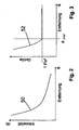
- FIG. 2 is a diagram illustrating the dependence of the intensity of the radiation energy or the irradiance of the incident on the sensor surface of an image detection sensor of the camera system 12 shows an image of an object generating light from the distance of the object to the sensor surface.
- the graph 50 shows the course of the intensity decrease of the radiation energy of a radiation source with the increasing distance of the radiation source or of the object to the sensor surface of the image detection sensor.
- the radiation source is in particular a lamp of a motor vehicle.
- FIG. 3 a diagram is shown, in which the size of the image of the object is shown as a function of the distance of the object to the sensor surface.
- the course of the graph 52 shows that the size of the image of the object can only be detected with the aid of the image acquisition sensor until the size of the image falls below the area of a pixel detection element. For a size smaller than the area of a pixel detection element, the image of the object is only taken on a part of a pixel detection element.
- FIG. 4 is a diagram with a dependency of the determined by the pixel detection elements brightness or gray value of the distance between the sensor surface and the object shown. If the object is slightly removed from the sensor surface, the object is imaged onto several image capture areas. As a result, each pixel detection element whose pixel detection area is completely covered by the image of the object outputs a constant maximum brightness value. If the image of the object is imaged with increasing distance only on a part of the pixel detection area of a pixel detection element, the radiation energy incident on this partial area of the pixel detection element is constant, but the pixel detection element only becomes the averaged over the entire image capture area of the pixel detection element averaged brightness or gray value output.
- the change in brightness caused thereby is represented by the graph 54 where the brightness value decreases after the distance between the object and the sensor surface has increased so that the image at d 1Pix 2 marked spot the image of the object is only a part of the image capture area of the pixel detection element takes place.
- FIG. 4 a decrease in brightness is shown when the image of the object is smaller than the pixel detection area of the pixel detection element. This is the case when the environment of the object is darker than the object itself. In other embodiments, the environment of the object is brighter than the object itself, so that then an increase in brightness from the point d 1Pix 2 he follows.
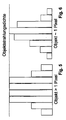
- FIGS. 5 to 7 the imaging of objects as a function of the distance of the object to the sensor surface of an image acquisition sensor of the camera system 12 is shown.
- FIG. 5 the brightness values of eight adjacent pixel detection areas are shown, wherein the object has such a size and a distance to the camera system 12 that four adjacent pixel detection areas are completely covered by the image of the object and each output a gray value corresponding to the light emitted by the object.
- the object has a greater distance to the camera system 12, so that the image of the object of the eight adjacent pixel detection areas only the fifth pixel detection area completely covered.
- the position and size of the image of the object on the sensor surface can still be determined with sufficient accuracy.
- FIG. 7 is the object opposite the FIGS. 5 and 6 arranged at an even greater distance to the camera system 12, so that the image of the object is imaged on the adjacent pixel detection elements only with a relatively low detected average radiation intensity.
- none of the pixel detectors can detect the actual radiant intensity of the light emitted by the object, so that neither the correct brightness nor the correct size of the image of the object or the correct position of the image of the object on the sensor surface of the image sensing sensor can be determined.
- FIGS. 8 to 11 the chain of transfer elements for imaging the object on the sensor surface of the image acquisition unit and for generating and outputting the brightness values corresponding to the image is shown schematically.
- the object itself is shown schematically.
- the image of the object is changed by the optical system of the camera system 12 or by their point transfer function such that an in FIG. 9 shown intensity distribution of the radiated from the object and the optical system of the camera system 12 supplied light is effected.
- a point-shaped object is imaged on at least one pixel detection element or a plurality of adjacent pixel detection elements.
- the incident on three adjacent pixel detection elements in the present embodiment is in FIG. 10 shown, wherein the largest pixel on the central pixel detection element Amount of light according to the in FIG.
- FIG. 11 displayed brightness values shown schematically. It can be seen that the same brightness values are output for the left pixel detection element and the right pixel detection element, although different amounts of light have impinged on these pixel detection elements, as shown in FIG. 10 is shown. However, this difference due to the digitization or the resolution of the digitized signal is no longer included as information in the output signal.
- Conventional image acquisition systems and camera systems 12 have a resolution of 256 to 4095 gray levels, so that the determined brightness values must be normalized to these gray levels. This standardization leads to one with the help of FIGS. 10 and 11 represented loss of information.
- the output signal shown in the prior art is a sufficiently accurate determination of the object properties of in FIG. 8 object can not be determined.
- the position of the image of the object on the sensor surface and the size of the image of the object on the sensor surface can not be determined with sufficient accuracy.
- the invention is preferably based on the assumption that the luminous intensity or the minimum luminous intensity of a luminaire or light source as a property of the light source is constant and independent of the distance between the light source and the sensor surface. If this assumed light intensity is assumed, may be determined based on the total amount of light incident on the adjacent picture elements by the image of the object, the actual size and / or the actual position of the image of the object. As a total amount of light impinging on the picture elements by the image of the object, the difference in brightness to further neighboring pixel elements is preferably determined on which the image of the object is not imaged. The actual size, ie the actual area, of the image on the sensor surface can thereby be easily calculated.
- the object size itself or the ratio of the size of the object to a distance or to the size of a further detected object can be determined with the aid of this information.
- the size of a tail lamp with respect to the distance between two tail lights of a motor vehicle can be determined and checked for plausibility.
- the actual position of the image of the object on the sensor surface can be determined by the light distribution to different adjacent pixel areas. This position can be specified as a coordinate or given when subdividing the grid-shaped pixel elements into subpixel elements using the coordinates of these subpixel elements.
- the intensity distribution is caused in particular by an aberration or by a plurality of aberrations of the optical system of the camera system 12.
- FIGS. 12 to 14 is a model based reconstruction of some features of the object in FIG. 12 shown, whose image has been detected by means of the camera system 12, wherein three pixel detection elements of the camera system 12 detect and output the brightness values caused by the image of the object.
- the point distribution function of the optical system of the camera system 12 is shown.
- the brightness values are inverted using the point transfer function, so that the actual image size of the in FIG. 14 represented, the actual light intensity of the light emitted by the object and / or the actual position of the object can be determined.
Landscapes
- Engineering & Computer Science (AREA)
- Physics & Mathematics (AREA)
- General Physics & Mathematics (AREA)
- Theoretical Computer Science (AREA)
- Multimedia (AREA)
- Computer Vision & Pattern Recognition (AREA)
- Image Analysis (AREA)
- Image Processing (AREA)
Claims (14)
- Procédé de traitement de données d'image,
selon lequel les données d'image d'au moins une image détectée pixel par pixel au moyen d'une unité de détection d'image (12) comprenant un capteur de détection d'image doté de zones de détection de pixel disposées en trame sont traitées,
au moins une variation d'une valeur de couleur et/ou de luminosité au-dessus d'au moins deux zones de détection de pixel étant déterminée, ladite variation devant être imputée à la répartition des intensités par le système optique de l'unité de détection d'image (12) lors de la reproduction d'un objet émettant ou réfléchissant de la lumière sur les zones de détection de pixel, objet dont la reproduction sur la surface de détection formée par les zones de détection d'image sans cette répartition des intensités serait inférieure ou égale à la grandeur d'une zone de détection de pixel, caractérisé en ce que
la grandeur de reproduction effective de l'objet et/ou la position effective de la reproduction de l'objet sans la répartition des intensités provoquée par le système optique de l'unité de traitement d'image (12) sont déterminées en fonction de la variation déterminée de la valeur de couleur et/ou de luminosité et/ou de l'amplitude de la valeur de couleur et/ou de luminosité déterminée dans au moins une zone de détection de pixel, et en ce que la position déterminée et/ou la grandeur effective déterminée de la reproduction de l'objet sont traitées au moyen d'un classificateur pour effectuer la classification de l'objet. - Procédé selon la revendication 1, caractérisé en ce qu'au moins une valeur d'amplitude de référence de la valeur d'image effective est préréglée, et
en ce que la quantité de lumière émise par l'objet reproduit et incidente sur ces zones de détection de pixel, répartie par la répartition des intensités sur les deux zones de détection de pixel ou plus, est déterminée, la grandeur de reproduction effective de l'objet étant déterminée en fonction de la valeur d'amplitude de référence. - Procédé selon l'une quelconque des revendications précédentes, caractérisé en ce que la ou les valeurs d'amplitude de référence correspondent à une intensité parmi l'intensité lumineuse minimale, l'intensité lumineuse maximale admissible et/ou l'intensité lumineuse habituelle d'un phare d'un véhicule automobile.
- Procédé selon l'une quelconque des revendications précédentes, caractérisé en ce que l'intensité lumineuse minimale et l'intensité lumineuse maximale admissible sont définies dans les règlements ECE et/ou dans les règlements édités par la Société des ingénieurs automobiles, et en ce que l'intensité lumineuse habituelle de l'intensité lumineuse moyenne correspond à un phare de modèles actuels de voiture et/ou de camion.
- Procédé selon l'une quelconque des revendications précédentes, caractérisé en ce que plusieurs valeurs d'amplitude de référence correspondant respectivement à l'intensité lumineuse d'un phare et/ou à une intensité lumineuse minimale, une intensité lumineuse maximale admissible et/ou une intensité lumineuse habituelle sont préréglées.
- Procédé selon l'une quelconque des revendications précédentes, caractérisé en ce qu'en raison de la répartition lumineuse de la lumière émise par l'objet et incidente sur les deux zones de détection de pixel ou plus, une position de la reproduction de l'objet sur la surface de détection est déterminée indépendamment des zones de détection de pixel disposées en trame ou grâce à l'indication de la position de la reproduction au moyen d'une sous-zone de détection de pixel.
- Procédé selon l'une quelconque des revendications précédentes, caractérisé en ce que la position effective de la reproduction de l'objet sur la surface de détection est déterminée au moyen d'au moins une aberration connue du système optique de l'unité de détection d'image (12) et de l'évolution déterminée de la valeur de couleur et/ou de luminosité.
- Procédé selon l'une quelconque des revendications précédentes, caractérisé en ce que la grandeur de reproduction effective de l'objet sur la surface de détection et/ou la position effective de l'objet sur la surface de détection est déterminée.
- Procédé selon l'une quelconque des revendications précédentes, selon lequel les zones de détection de pixel sont disposées dans un plan d'image de l'unité de détection d'image (12).
- Procédé selon l'une quelconque des revendications précédentes, caractérisé en ce que la répartition des intensités de la fonction de transfert de point de l'unité de détection d'image (12) est effectuée lors de la reproduction de l'objet.
- Procédé selon l'une quelconque des revendications précédentes, caractérisé en ce qu'un procédé de déconvolution est utilisé pour déterminer la grandeur de reproduction effective de l'objet et/ou pour déterminer la position effective de l'objet.
- Procédé selon l'une quelconque des revendications précédentes, caractérisé en ce que l'image est détectée au moyen d'une unité de détection d'image (12) disposée dans un véhicule automobile, de préférence au moyen d'une caméra avant monoculaire ou d'un appareil photo caméra.
- Procédé selon l'une quelconque des revendications précédentes, caractérisé en ce que plusieurs images dont les données sont traitées à plusieurs reprises sont déterminées successivement au moyen de l'unité de détection d'image (12), la position effective de la reproduction de l'objet étant déterminée et étant poursuivie sur plusieurs images enregistrées successivement, de préférence au moyen d'un procédé de localisation.
- Dispositif de détermination et de traitement de données d'image,
doté d'une unité de détection d'image (12) comprenant un capteur de détection d'image doté de zones de détection de pixel disposées en trame et destiné à détecter une image pixel par pixel, l'unité de détection d'image (12) produisant des données d'image correspondant à l'image,
ladite unité déterminant au moins une variation d'une valeur de couleur et/ou de luminosité au-dessus d'au moins deux zones de détection de pixel, ladite variation devant être imputée à la répartition des intensités par le système optique de l'unité de détection d'image (12) lors de la reproduction d'un objet émettant ou réfléchissant de la lumière sur les zones de détection de pixel, objet dont la reproduction sur la surface de détection formée par les zones de détection d'image dans le plan de l'image sans cette répartition des intensités serait inférieure ou égale à la grandeur d'une zone de détection de pixel, caractérisé en ce que le dispositif détermine, en fonction de la variation déterminée de la valeur de couleur et/ou de luminosité et/ou de l'amplitude de la valeur de couleur et/ou de luminosité déterminée dans au moins une zone de détection de pixel, la grandeur de reproduction effective de l'objet et/ou la position effective de la reproduction de l'objet sans la répartition des intensités provoquée par le système optique de l'unité de traitement d'image (12), et en ce que la position déterminée et/ou la grandeur effective déterminée de la reproduction de l'objet sont traitées au moyen d'un classificateur pour effectuer la classification de l'objet.
Applications Claiming Priority (1)
| Application Number | Priority Date | Filing Date | Title |
|---|---|---|---|
| DE102008014630A DE102008014630A1 (de) | 2008-03-17 | 2008-03-17 | Verfahren und Vorrichtung zum Verarbeiten von Bilddaten |
Publications (3)
| Publication Number | Publication Date |
|---|---|
| EP2103984A2 EP2103984A2 (fr) | 2009-09-23 |
| EP2103984A3 EP2103984A3 (fr) | 2011-11-09 |
| EP2103984B1 true EP2103984B1 (fr) | 2013-04-24 |
Family
ID=40756917
Family Applications (1)
| Application Number | Title | Priority Date | Filing Date |
|---|---|---|---|
| EP09155344.6A Active EP2103984B1 (fr) | 2008-03-17 | 2009-03-17 | Procédé et dispositif de traitement de données d'image |
Country Status (2)
| Country | Link |
|---|---|
| EP (1) | EP2103984B1 (fr) |
| DE (1) | DE102008014630A1 (fr) |
Families Citing this family (2)
| Publication number | Priority date | Publication date | Assignee | Title |
|---|---|---|---|---|
| DE102011109387A1 (de) | 2011-08-04 | 2013-02-07 | Conti Temic Microelectronic Gmbh | Verfahren zur Erkennung von Verkehrszeichen |
| DE102013219909A1 (de) * | 2013-10-01 | 2015-04-02 | Conti Temic Microelectronic Gmbh | Verfahren und Vorrichtung zur Erkennung von Verkehrszeichen |
Family Cites Families (4)
| Publication number | Priority date | Publication date | Assignee | Title |
|---|---|---|---|---|
| JP4253271B2 (ja) * | 2003-08-11 | 2009-04-08 | 株式会社日立製作所 | 画像処理システム及び車両制御システム |
| US20050147313A1 (en) * | 2003-12-29 | 2005-07-07 | Dimitry Gorinevsky | Image deblurring with a systolic array processor |
| EP1837803A3 (fr) * | 2006-03-24 | 2008-05-14 | MobilEye Technologies, Ltd. | Détection de phare, feu rouge arrière et réverbère |
| JP4853160B2 (ja) * | 2006-08-02 | 2012-01-11 | 株式会社デンソー | 車両検出装置及びヘッドランプ制御装置 |
-
2008
- 2008-03-17 DE DE102008014630A patent/DE102008014630A1/de not_active Withdrawn
-
2009
- 2009-03-17 EP EP09155344.6A patent/EP2103984B1/fr active Active
Also Published As
| Publication number | Publication date |
|---|---|
| DE102008014630A1 (de) | 2009-09-24 |
| EP2103984A3 (fr) | 2011-11-09 |
| EP2103984A2 (fr) | 2009-09-23 |
Similar Documents
| Publication | Publication Date | Title |
|---|---|---|
| DE102007000420B4 (de) | Fahrzeuginterne Einrichtung zum Erfassen von Fahrzeugen und Vorrichtung zum Steuern von Scheinwerfern durch Verwenden der Einrichtung | |
| EP2748032B1 (fr) | Procédé et dispositif de commande d'un phare de véhicule | |
| DE102010039092B4 (de) | Verfahren und Steuergerät zum Ermitteln eines Abstandes eines Objektes von einem Fahrzeug | |
| EP2788224A1 (fr) | Procédé et dispositif permettant d'identifier une situation de freinage | |
| DE102015121952A1 (de) | Verfahren zum Identifizieren eines Objektes in einem Umgebungsbereich eines Kraftfahrzeugs, Fahrerassistenzsystem sowie Kraftfahrzeug | |
| EP3329241B1 (fr) | Diagnostic des feux au moyen d'un système de caméra(s) d'un véhicule | |
| DE102011081392A1 (de) | Verfahren zur Bestimmung einer Leuchtweite zumindest eines Scheinwerfers und Verfahren zur Kalibrierung einer Lichtaussendung zumindest eines Scheinwerfers eines Fahrzeugs | |
| EP2150939A1 (fr) | Procédé et dispositif pour déterminer la position d'un panneau de signalisation | |
| WO2018014917A1 (fr) | Dispositif de prise de vues servant à capter une zone environnante d'un véhicule équipé dudit dispositif et procédé permettant d'obtenir une fonction d'aide à la conduite | |
| DE102014217366A1 (de) | Verfahren und Vorrichtung zum Anpassen einer Helligkeit eines Scheinwerfers für ein Fahrzeug | |
| DE102018212506A1 (de) | Verfahren zum Betrieb einer Fahrfunktion eines Fahrzeugs | |
| DE102007021580B4 (de) | Verfahren und Vorrichtung zum Ermitteln der fahrzeugrelevanten Verkehrszeichen | |
| DE102013022050A1 (de) | Verfahren zum Verfolgen eines Zielfahrzeugs, insbesondere eines Motorrads, mittels eines Kraftfahrzeugs, Kamerasystem und Kraftfahrzeug | |
| EP2562685B1 (fr) | Procédé et dispositif de classification d'un objet lumineux situé à l'avant d'un véhicule | |
| EP2103984B1 (fr) | Procédé et dispositif de traitement de données d'image | |
| DE102006004770B4 (de) | Verfahren zur bildgestützten Erkennung von Fahrzeugen im Umfeld eines Sraßenfahrzeugs | |
| DE102015223500A1 (de) | Verfahren und Vorrichtung zur Prüfung der Funktionalität einer außenseitigen Lichteinrichtung eines Fahrzeugs | |
| EP2131308B1 (fr) | Procédé et dispositif de classification d'un objet détecté dans au moins une image d'une zone à l'avant d'un véhicule | |
| DE102011081391A1 (de) | Verfahren und Vorrichtung zum Erkennen von Störobjekten in der Umgebungsluft eines Fahrzeugs | |
| DE102009045558A1 (de) | Kamerasystem | |
| EP1962245B1 (fr) | Procédé et dispositif de détermination de l'état de déplacement d'objets | |
| DE102006043433B4 (de) | Verfahren zur bildgestützten Bestimmung der Fahrtrichtung von Fahrzeugen | |
| EP4228923A1 (fr) | Appareil d'éclairage pour un phare de véhicule à moteur | |
| DE102007021577A1 (de) | Verfahren und Vorrichtung zur Verkehrszeichenerkennung | |
| DE102021005927A1 (de) | Verfahren zum Überprüfen einer Beleuchtungseinrichtung |
Legal Events
| Date | Code | Title | Description |
|---|---|---|---|
| PUAI | Public reference made under article 153(3) epc to a published international application that has entered the european phase |
Free format text: ORIGINAL CODE: 0009012 |
|
| AK | Designated contracting states |
Kind code of ref document: A2 Designated state(s): AT BE BG CH CY CZ DE DK EE ES FI FR GB GR HR HU IE IS IT LI LT LU LV MC MK MT NL NO PL PT RO SE SI SK TR |
|
| AX | Request for extension of the european patent |
Extension state: AL BA RS |
|
| REG | Reference to a national code |
Ref country code: DE Ref legal event code: R079 Ref document number: 502009006918 Country of ref document: DE Free format text: PREVIOUS MAIN CLASS: G02B0027000000 Ipc: G06T0005000000 |
|
| PUAL | Search report despatched |
Free format text: ORIGINAL CODE: 0009013 |
|
| AK | Designated contracting states |
Kind code of ref document: A3 Designated state(s): AT BE BG CH CY CZ DE DK EE ES FI FR GB GR HR HU IE IS IT LI LT LU LV MC MK MT NL NO PL PT RO SE SI SK TR |
|
| AX | Request for extension of the european patent |
Extension state: AL BA RS |
|
| RIC1 | Information provided on ipc code assigned before grant |
Ipc: G06T 5/00 20060101AFI20110930BHEP Ipc: G06K 9/00 20060101ALI20110930BHEP Ipc: G06T 7/00 20060101ALI20110930BHEP |
|
| 17P | Request for examination filed |
Effective date: 20120509 |
|
| AKX | Designation fees paid |
Designated state(s): DE FR GB |
|
| GRAP | Despatch of communication of intention to grant a patent |
Free format text: ORIGINAL CODE: EPIDOSNIGR1 |
|
| GRAS | Grant fee paid |
Free format text: ORIGINAL CODE: EPIDOSNIGR3 |
|
| GRAP | Despatch of communication of intention to grant a patent |
Free format text: ORIGINAL CODE: EPIDOSNIGR1 |
|
| GRAA | (expected) grant |
Free format text: ORIGINAL CODE: 0009210 |
|
| AK | Designated contracting states |
Kind code of ref document: B1 Designated state(s): DE FR GB |
|
| REG | Reference to a national code |
Ref country code: GB Ref legal event code: FG4D Free format text: NOT ENGLISH |
|
| REG | Reference to a national code |
Ref country code: DE Ref legal event code: R096 Ref document number: 502009006918 Country of ref document: DE Effective date: 20130620 |
|
| PLBE | No opposition filed within time limit |
Free format text: ORIGINAL CODE: 0009261 |
|
| STAA | Information on the status of an ep patent application or granted ep patent |
Free format text: STATUS: NO OPPOSITION FILED WITHIN TIME LIMIT |
|
| 26N | No opposition filed |
Effective date: 20140127 |
|
| REG | Reference to a national code |
Ref country code: DE Ref legal event code: R097 Ref document number: 502009006918 Country of ref document: DE Effective date: 20140127 |
|
| REG | Reference to a national code |
Ref country code: DE Ref legal event code: R082 Ref document number: 502009006918 Country of ref document: DE Representative=s name: SCHAUMBURG & PARTNER PATENTANWAELTE GBR, DE Ref country code: DE Ref legal event code: R082 Ref document number: 502009006918 Country of ref document: DE Representative=s name: SCHAUMBURG UND PARTNER PATENTANWAELTE MBB, DE |
|
| REG | Reference to a national code |
Ref country code: FR Ref legal event code: PLFP Year of fee payment: 8 |
|
| REG | Reference to a national code |
Ref country code: FR Ref legal event code: PLFP Year of fee payment: 9 |
|
| REG | Reference to a national code |
Ref country code: DE Ref legal event code: R081 Ref document number: 502009006918 Country of ref document: DE Owner name: CARIAD SE, DE Free format text: FORMER OWNER: HELLA KGAA HUECK & CO., 59557 LIPPSTADT, DE Ref legal event code: R082 Country of ref document: DE Ref country code: DE Ref document number: 502009006918 Representative=s name: SCHAUMBURG UND PARTNER PATENTANWAELTE MBB, DE Ref country code: DE Ref legal event code: R081 Ref document number: 502009006918 Country of ref document: DE Owner name: CAR.SOFTWARE ESTONIA AS, EE Free format text: FORMER OWNER: HELLA KGAA HUECK & CO., 59557 LIPPSTADT, DE Ref country code: DE Ref legal event code: R081 Ref document number: 502009006918 Country of ref document: DE Owner name: HELLA GMBH & CO. KGAA, DE Free format text: FORMER OWNER: HELLA KGAA HUECK & CO., 59557 LIPPSTADT, DE |
|
| REG | Reference to a national code |
Ref country code: FR Ref legal event code: PLFP Year of fee payment: 10 |
|
| REG | Reference to a national code |
Ref country code: DE Ref legal event code: R081 Ref document number: 502009006918 Country of ref document: DE Owner name: CARIAD SE, DE Free format text: FORMER OWNER: HELLA GMBH & CO. KGAA, 59557 LIPPSTADT, DE Ref country code: DE Ref legal event code: R082 Ref document number: 502009006918 Country of ref document: DE Ref country code: DE Ref legal event code: R081 Ref document number: 502009006918 Country of ref document: DE Owner name: CAR.SOFTWARE ESTONIA AS, EE Free format text: FORMER OWNER: HELLA GMBH & CO. KGAA, 59557 LIPPSTADT, DE |
|
| REG | Reference to a national code |
Ref country code: GB Ref legal event code: 732E Free format text: REGISTERED BETWEEN 20210930 AND 20211006 |
|
| REG | Reference to a national code |
Ref country code: GB Ref legal event code: 732E Free format text: REGISTERED BETWEEN 20220513 AND 20220518 |
|
| REG | Reference to a national code |
Ref country code: DE Ref legal event code: R081 Ref document number: 502009006918 Country of ref document: DE Owner name: CARIAD SE, DE Free format text: FORMER OWNER: CAR.SOFTWARE ESTONIA AS, TALLINN, EE |
|
| PGFP | Annual fee paid to national office [announced via postgrant information from national office to epo] |
Ref country code: GB Payment date: 20240320 Year of fee payment: 16 |
|
| PGFP | Annual fee paid to national office [announced via postgrant information from national office to epo] |
Ref country code: FR Payment date: 20240321 Year of fee payment: 16 |
|
| PGFP | Annual fee paid to national office [announced via postgrant information from national office to epo] |
Ref country code: DE Payment date: 20240403 Year of fee payment: 16 |