EP2103793A2 - Flow rate control system for turbocharger - Google Patents
Flow rate control system for turbocharger Download PDFInfo
- Publication number
- EP2103793A2 EP2103793A2 EP09155507A EP09155507A EP2103793A2 EP 2103793 A2 EP2103793 A2 EP 2103793A2 EP 09155507 A EP09155507 A EP 09155507A EP 09155507 A EP09155507 A EP 09155507A EP 2103793 A2 EP2103793 A2 EP 2103793A2
- Authority
- EP
- European Patent Office
- Prior art keywords
- peripheral member
- guide portions
- inner peripheral
- gas passages
- outer peripheral
- Prior art date
- Legal status (The legal status is an assumption and is not a legal conclusion. Google has not performed a legal analysis and makes no representation as to the accuracy of the status listed.)
- Withdrawn
Links
- 230000002093 peripheral effect Effects 0.000 claims abstract description 123
- 238000010276 construction Methods 0.000 description 2
- 230000007246 mechanism Effects 0.000 description 2
- 238000002485 combustion reaction Methods 0.000 description 1
- 238000007599 discharging Methods 0.000 description 1
- 230000000694 effects Effects 0.000 description 1
- 239000000203 mixture Substances 0.000 description 1
- 230000004048 modification Effects 0.000 description 1
- 238000012986 modification Methods 0.000 description 1
- 239000002699 waste material Substances 0.000 description 1
Images


Classifications
-
- F—MECHANICAL ENGINEERING; LIGHTING; HEATING; WEAPONS; BLASTING
- F01—MACHINES OR ENGINES IN GENERAL; ENGINE PLANTS IN GENERAL; STEAM ENGINES
- F01D—NON-POSITIVE DISPLACEMENT MACHINES OR ENGINES, e.g. STEAM TURBINES
- F01D17/00—Regulating or controlling by varying flow
- F01D17/10—Final actuators
- F01D17/12—Final actuators arranged in stator parts
- F01D17/14—Final actuators arranged in stator parts varying effective cross-sectional area of nozzles or guide conduits
- F01D17/16—Final actuators arranged in stator parts varying effective cross-sectional area of nozzles or guide conduits by means of nozzle vanes
- F01D17/165—Final actuators arranged in stator parts varying effective cross-sectional area of nozzles or guide conduits by means of nozzle vanes for radial flow, i.e. the vanes turning around axes which are essentially parallel to the rotor centre line
-
- F—MECHANICAL ENGINEERING; LIGHTING; HEATING; WEAPONS; BLASTING
- F01—MACHINES OR ENGINES IN GENERAL; ENGINE PLANTS IN GENERAL; STEAM ENGINES
- F01D—NON-POSITIVE DISPLACEMENT MACHINES OR ENGINES, e.g. STEAM TURBINES
- F01D17/00—Regulating or controlling by varying flow
- F01D17/10—Final actuators
- F01D17/12—Final actuators arranged in stator parts
- F01D17/14—Final actuators arranged in stator parts varying effective cross-sectional area of nozzles or guide conduits
- F01D17/141—Final actuators arranged in stator parts varying effective cross-sectional area of nozzles or guide conduits by means of shiftable members or valves obturating part of the flow path
-
- F—MECHANICAL ENGINEERING; LIGHTING; HEATING; WEAPONS; BLASTING
- F05—INDEXING SCHEMES RELATING TO ENGINES OR PUMPS IN VARIOUS SUBCLASSES OF CLASSES F01-F04
- F05D—INDEXING SCHEME FOR ASPECTS RELATING TO NON-POSITIVE-DISPLACEMENT MACHINES OR ENGINES, GAS-TURBINES OR JET-PROPULSION PLANTS
- F05D2220/00—Application
- F05D2220/40—Application in turbochargers
-
- F—MECHANICAL ENGINEERING; LIGHTING; HEATING; WEAPONS; BLASTING
- F05—INDEXING SCHEMES RELATING TO ENGINES OR PUMPS IN VARIOUS SUBCLASSES OF CLASSES F01-F04
- F05D—INDEXING SCHEME FOR ASPECTS RELATING TO NON-POSITIVE-DISPLACEMENT MACHINES OR ENGINES, GAS-TURBINES OR JET-PROPULSION PLANTS
- F05D2250/00—Geometry
- F05D2250/30—Arrangement of components
- F05D2250/35—Arrangement of components rotated
Definitions
- the invention relates to a turbocharger, and more specifically, to a turbocharger that changes the flow rate of gas to a turbine wheel.
- JP-A-2000-199433 describes turbocharger in which a large-diameter disc portion is provided between two levers so as to abut against one of both the levers.
- the levers are turned synchronously with each other.
- the large-diameter disc portion comes into abutment on one of both the levers to thereby control the angle of a nozzle vane when fully open.
- the large-diameter disc portion comes into abutment on the other of both the levers to thereby control the angle of the nozzle vane when fully closed.
- JP-A-11-148364 describes a turning center of a turbine-side movable nozzle vane that is provided on an inner edge portion of a vane support body, and a turning center of a scroll-side movable nozzle vane that is provided on an outer edge portion of the vane support body.
- a nozzle vane that assumes a fully open position when a stopper hits one longitudinal end of a guide, and assumes a fully closed position when the stopper is in contact with the other longitudinal end of the guide is described in Japanese Patent Application Publication No. 10-37754 ( JP-A-10-37754 ).
- JP-A-5-18258 there is described an art in which one of flow passage walls on both sides, which sandwich a nozzle vane, is a movable wall turnable around a turbine wheel shaft, and the other is a fixed wall facing the movable wall.
- variable nozzle turbochargers there is a problem in that the flow of gas in a turbine wheel cannot be sufficiently reduced.
- the invention provides a turbocharger capable of sufficiently reducing the flow of gas to a turbine wheel.
- a turbocharger includes: a turbine wheel, an inner peripheral member that is provided outside the turbine wheel and that guides exhaust gas to the turbine wheel, an annular outer peripheral member that is provided adjacent to and outside of the inner peripheral member and that is rotatable relative to the inner peripheral member in a circumferential direction, a plurality of inner guide portions that is provided on the inner peripheral member and that define inner gas passages between successive inner guide portions, and a plurality of outer guide portions that is provided on the outer peripheral member and that define gas passages between successive outer guide portions.
- the flow of gas to the turbine wheel through the inner gas passages and the outer gas passages is adjusted by turning one of the outer peripheral member or the inner peripheral member with respect to the other of the outer peripheral member or the inner peripheral member so that the inner guide portions restrict the flow of the outer gas passages in accordance with the degree to which the outer peripheral member or the inner peripheral member is turned.
- the inner guide portions close the outer gas passages in accordance with the turning position of the outer peripheral member with respect to the inner peripheral member.
- the flow of gas to the turbine wheel through the gas passages may be restricted or shut off.
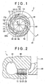
- FIG. 1 is a plan view of a turbocharger according to the first embodiment of the invention.
- a turbocharger 1 has a turbine wheel 30, and a turbine housing 40 in which the turbine wheel 30 is accommodated.
- An inner peripheral member 23 and an outer peripheral member 13 are accommodated in the turbine housing 40 and disposed outside the turbine wheel 30.
- Both the inner peripheral member 23 and the outer peripheral member 13 are ring shaped, and are slidably in contact with each other.
- the inner peripheral member 23 may be fixed in position, and the outer peripheral member 13 may be turnably provided.
- the outer peripheral member 13 may be fixed in position, and the inner peripheral member 23 may be a turnably provided.
- the inner peripheral member 23 and the outer peripheral member 13 are provided with inner guide portions 21 and outer guide portions 11 respectively, which define gas passages 22 and gas passages 12 provided between the respective inner guide portions 21 and outer guide portions 11.
- the sides of each inner guide portions 21 are curved.
- the inner guide portions 21 are disposed at regular intervals on the inner peripheral member 23 such that the outer peripheral edges 21a of the inner guide portions 21 extend along the outer peripheral edge of the inner peripheral member 23.
- the sides of each outer guide portions 11 are curved.
- the outer guide portions 11 are disposed at regular intervals on the outer peripheral member 13 such that the inner peripheral edges 11a extend along the inner peripheral edge of the outer peripheral member 13.
- the inner guide portion 21 and the outer guide portions 11 are designed to,slide with respect to each other as well.
- the gas passages 22 and 12 are concave, and exhaust gas supplied from a gas passage 41 of the turbine housing 40 flows toward the turbine wheel 30 in directions indicated by arrows 42 via the gas passages 12 and 22. Thus, the turbine wheel 30 is rotated.
- the turbine wheel 30 is connected to a turbine shaft, and the turbine shaft is, in turn, connected to a compressor.
- the compressor compresses mixture or intake air.
- FIG. 2 is a sectional view taken along a line II-II in FIG. 1 .
- the turbine wheel 30 is held rotatable around a centerline 31.
- the turbine housing 40 is provided on an outer periphery of the turbine wheel 30, and the turbine housing 40 is provided with the gas passage 41, which assumes a spiral shape.
- the inner guide portions 21 are mounted on the inner peripheral member 23, and the outer guide portions 11 are mounted on the outer peripheral member 13.
- each outer guide portion 11 and the corresponding inner guide portion 21 are in contact with each other.
- the invention is not limited to this construction.
- Each of the guide portions 11 and a corresponding one of the guide portions 21 may be slightly spaced apart from each other.
- FIG. 3 is a view showing the turbocharger in which the inner peripheral member is relative to the outer peripheral member where the flow of gas is shut off.
- the inner guide portions 21 block the outer gas passages 12.
- gas cannot be supplied from the out gas passages 12 to the inner gas passages 22.
- gas exhaust gas
- gas cannot be introduced from the outer periphery side to the inner periphery side, thereby significantly restricting the flow of gas toward the turbine wheel 30.
- FIG. 4 is a graph showing a relationship between a relative rotational angle between the inner peripheral member and the outer peripheral member and an area of a nozzle throat.
- the axis of ordinate “AREA OF NOZZLE THROAT” represents the flow rate of gas through the turbine wheel 30 via the outer gas passage 12 and the inner gas passage 22.
- the flow rate of gas through the gas passages may be changed in a continuous manner.
- the turbocharger 1 is equipped with the turbine wheel 30; the annular inner peripheral member 23 that is located outside the turbine wheel 30 and that guides gas to the turbine wheel 30; and the outer peripheral member 13 that is located to the outside of and adjacent to the inner peripheral member 23 and that turns with respect to the inner peripheral member 23 in a circumferential direction.
- the inner peripheral member 23 and the outer peripheral member 13 are provided respectively with the plurality of the outer guide portions 11 and inner guide portions 21 that guide gas inward from the outer periphery, and the outer gas passages 12 and inner gas passages 22 are provided between the plurality of the respective outer guide portions 11 and inner guide portions 21.
- the inner guide portions 21 close the outer gas passages 12 in accordance with the turning position of the outer peripheral member 13 with respect to the inner peripheral member 23, so that the flow of gas to the turbine wheel 30 through the gas passages may be restricted or shut off.
- the ring-like inner peripheral member 23 and the ring-like outer peripheral member 13 are rotated relative to each other, and the area of the nozzle throat may thereby be adjusted. Furthermore, the nozzle throat may be closed fully so that the flow of gas is shut off.
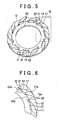
- FIG. 5 is a perspective view showing part of a turbocharger according to the second embodiment of the invention.
- FIG. 6 is a view showing a region surrounded by VI in FIG. 5 on an enlarged scale.
- the turbocharger 1 according to the second embodiment of the invention differs from the turbocharger 1 according to the first embodiment of the invention in that the radial thickness of the inner guide portions 21 is smaller than in the first embodiment of the invention.
- the thickness of the inner guide portions 21 By reducing the thickness of the inner guide portions 21, the distance between the outer edge portion of the inner peripheral member 23 and the turbine wheel may be reduced.
- the area of the throat in the traveling direction of gas may be changed smoothly.
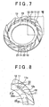
- FIG. 7 is a perspective view of the turbocharger when the nozzle throat is fully closed.
- FIG 8 is a view showing a region surrounded by VIII in FIG. 7 on an enlarged scale. Referring to FIGS. 7 and 8 , when the nozzle throat is fully closed, the inner guide portions 21 block off the respective outer gas passages 12. Thus, the flow of gas from the outer peripheral portion toward the inner peripheral portion can be shut off.
- FIG. 9 is a sectional view of a turbocharger according to the third embodiment of the invention.
- FIG. 10 is a plan view of the turbocharger according to the third embodiment of the invention. Referring to FIGS. 9 and 10 , in the turbocharger 1 according to the third embodiment of the invention, the turbine housing 40 is provided with a drill path 45 as a waste gate.
- the drill path 45 is a passage for discharging gas in the gas passage 41 provided in the turbine housing 40 without the intermediary of the turbine wheel 30. As shown in FIG. 10 , when the inner guide portions 21 are positioned to fully close all the outer gas passages 12, the drill path 45 is closed by the outer guide portions 11, so that no gas flows through the drill path 45.
- a single drill path 45 may be provided as shown in FIG. 10 .
- a plurality of drill paths 45 may be provided.
- the opening portion of the drill path 45 is shown formed above the outer guide portions 11, but may be formed above the inner guide portions 21 instead.
- the inner peripheral edge 11a of each outer guide portions 11 is the same with the inner peripheral edge 12a of each outer gas passages 12.
- the width of the inner peripheral edge 11a of each outer guide portions 11 may differ from that of each outer gas passages 12.
- the inner peripheral edge 12a of each outer gas passages 12 is the same with as the outer peripheral edge 21a of each inner guide portions 21.
- the width of the outer peripheral edge 21a of each inner guide portions 21 may be longer than that of the inner peripheral edge 12a of each gas passages 12.
- each outer guide portions 11 and the outer peripheral edge 21a of each inner guide portions 21 may be equal in width to each other or different in width from each other.
- the internal combustion engine may be a gasoline engine or a diesel engine.
- a rotary engine as well as a reciprocal engine may be employed.
- the invention is applicable to various forms of engines such as inline engines, V-type engines, horizontally-opposed engines, W-type engines, and the like.
- the mechanism for turning the turbine wheel 30 is not limited to mechanisms utilizing exhaust gas only.
- a motor may be used to assist the rotation of the turbine wheel 30.
- EGR exhaust gas recirculation
- a turbocharger 1 includes a turbine wheel 30, an inner peripheral member 23 provided outside the turbine wheel 30, and an outer peripheral member 13 provided outside the inner peripheral member 23 that can turn relative to the inner peripheral member 23 in the circumferential direction.
- the inner peripheral member 23 and the outer peripheral member 13 are provided with a plurality of inner guide portions 21 and a plurality of outer guide portions 11, respectively, that define gas passages 22 and 12 between successive guide portions 21, 11.
- the flow of gas to the turbine wheel 30 through the gas passages may be adjusted by turning one of the outer peripheral member 13 or the inner peripheral member 23 so that the inner guide portions 21 restrict the flow of gas through the gas passages 12 of the outer peripheral member 13.
Landscapes
- Engineering & Computer Science (AREA)
- Mechanical Engineering (AREA)
- General Engineering & Computer Science (AREA)
- Supercharger (AREA)
- Control Of Turbines (AREA)
Abstract
Description
- The invention relates to a turbocharger, and more specifically, to a turbocharger that changes the flow rate of gas to a turbine wheel.
- Japanese Patent Application Publication No.
2000-199433 JP-A-2000-199433 - Japanese Patent Application Publication No.
11-148364 JP-A-11-148364 - A nozzle vane that assumes a fully open position when a stopper hits one longitudinal end of a guide, and assumes a fully closed position when the stopper is in contact with the other longitudinal end of the guide is described in Japanese Patent Application Publication No.
10-37754 JP-A-10-37754 - In
JP-A-5-18258 - However, in the described variable nozzle turbochargers, there is a problem in that the flow of gas in a turbine wheel cannot be sufficiently reduced.
- The invention provides a turbocharger capable of sufficiently reducing the flow of gas to a turbine wheel.
- A turbocharger according to one aspect of the invention includes: a turbine wheel, an inner peripheral member that is provided outside the turbine wheel and that guides exhaust gas to the turbine wheel, an annular outer peripheral member that is provided adjacent to and outside of the inner peripheral member and that is rotatable relative to the inner peripheral member in a circumferential direction, a plurality of inner guide portions that is provided on the inner peripheral member and that define inner gas passages between successive inner guide portions, and a plurality of outer guide portions that is provided on the outer peripheral member and that define gas passages between successive outer guide portions. The flow of gas to the turbine wheel through the inner gas passages and the outer gas passages is adjusted by turning one of the outer peripheral member or the inner peripheral member with respect to the other of the outer peripheral member or the inner peripheral member so that the inner guide portions restrict the flow of the outer gas passages in accordance with the degree to which the outer peripheral member or the inner peripheral member is turned.
- In the turbocharger constructed as described above, the inner guide portions close the outer gas passages in accordance with the turning position of the outer peripheral member with respect to the inner peripheral member. Thus, the flow of gas to the turbine wheel through the gas passages may be restricted or shut off. As a result, a turbocharger with a simple construction that can reliably regulate the flow of gas to the turbine wheel is provided.
- The features, advantages, and technical and industrial significance of this invention will be described in the following detailed description of example embodiments of the invention with reference to the accompanying drawings, in which like numerals denote like elements, and wherein:
-
FIG. 1 is a plan view of a turbocharger according to the first embodiment of the invention; -
FIG. 2 is a sectional view taken along a line II-II inFIG. 1 ; -
FIG. 3 is a view showing the turbocharger of the first embodiment in which an inner peripheral member is rotated to a position relative to an outer peripheral member where the flow of gas is shut off; -
FIG. 4 is a graph showing a relationship between a relative rotational angle between the inner peripheral member and the outer peripheral member and the area of a nozzle throat; -
FIG. 5 is a perspective view showing part of a turbocharger according to the second embodiment of the invention; -
FIG. 6 is a view showing a region surrounded by VI inFIG. 5 on an enlarged scale; -
FIG 7 is a perspective view of the turbocharger when fully closed; -
FIG. 8 is a plan view showing a region surrounded by VIII inFIG. 7 on an enlarged scale; -
FIG. 9 is a sectional view of a turbocharger according to the third embodiment of the invention; and -
FIG. 10 is a plan view of the turbocharger according to the third embodiment of the invention. - The embodiments of the invention will be described hereinafter with reference to the drawings. In the following embodiments of the invention, like or equivalent components are denoted by like reference symbols, and the description thereof will not be repeated. Further, it is also possible to combine the respective embodiments of the invention with one another.
-
FIG. 1 is a plan view of a turbocharger according to the first embodiment of the invention. Referring toFIG. 1 , aturbocharger 1 has aturbine wheel 30, and aturbine housing 40 in which theturbine wheel 30 is accommodated. An innerperipheral member 23 and an outerperipheral member 13 are accommodated in theturbine housing 40 and disposed outside theturbine wheel 30. - Both the inner
peripheral member 23 and the outerperipheral member 13 are ring shaped, and are slidably in contact with each other. The innerperipheral member 23 may be fixed in position, and the outerperipheral member 13 may be turnably provided. Conversely, the outerperipheral member 13 may be fixed in position, and the innerperipheral member 23 may be a turnably provided. - The inner
peripheral member 23 and the outerperipheral member 13 are provided withinner guide portions 21 andouter guide portions 11 respectively, which definegas passages 22 andgas passages 12 provided between the respectiveinner guide portions 21 andouter guide portions 11. The sides of eachinner guide portions 21 are curved. Theinner guide portions 21 are disposed at regular intervals on the innerperipheral member 23 such that the outerperipheral edges 21a of theinner guide portions 21 extend along the outer peripheral edge of the innerperipheral member 23. Similarly, the sides of eachouter guide portions 11 are curved. Theouter guide portions 11 are disposed at regular intervals on the outerperipheral member 13 such that the innerperipheral edges 11a extend along the inner peripheral edge of the outerperipheral member 13. Further, when the innerperipheral member 23 and the outerperipheral member 13 turn, theinner guide portion 21 and theouter guide portions 11 are designed to,slide with respect to each other as well. Thegas passages gas passage 41 of theturbine housing 40 flows toward theturbine wheel 30 in directions indicated byarrows 42 via thegas passages turbine wheel 30 is rotated. - The
turbine wheel 30 is connected to a turbine shaft, and the turbine shaft is, in turn, connected to a compressor. The compressor compresses mixture or intake air. -
FIG. 2 is a sectional view taken along a line II-II inFIG. 1 . Referring toFIG. 2 , theturbine wheel 30 is held rotatable around acenterline 31. Theturbine housing 40 is provided on an outer periphery of theturbine wheel 30, and theturbine housing 40 is provided with thegas passage 41, which assumes a spiral shape. - The
outer guide portions 11 andinner guide portions 21, which serve to supply gas toward theturbine wheel 30 and adjust the flow rate of the gas, are disposed on an outer peripheral portion of theturbine wheel 30. Theinner guide portions 21 are mounted on the innerperipheral member 23, and theouter guide portions 11 are mounted on the outerperipheral member 13. - In this example, each
outer guide portion 11 and the correspondinginner guide portion 21 are in contact with each other. However, the invention is not limited to this construction. Each of theguide portions 11 and a corresponding one of theguide portions 21 may be slightly spaced apart from each other. -
FIG. 3 is a view showing the turbocharger in which the inner peripheral member is relative to the outer peripheral member where the flow of gas is shut off. Referring toFIG. 3 , when the inner peripheral member is turned relative to the outer peripheral member, theinner guide portions 21 block theouter gas passages 12. Thus, gas cannot be supplied from the outgas passages 12 to theinner gas passages 22. As a result, gas (exhaust gas) cannot be introduced from the outer periphery side to the inner periphery side, thereby significantly restricting the flow of gas toward theturbine wheel 30. -
FIG. 4 is a graph showing a relationship between a relative rotational angle between the inner peripheral member and the outer peripheral member and an area of a nozzle throat. The axis of ordinate "AREA OF NOZZLE THROAT" represents the flow rate of gas through theturbine wheel 30 via theouter gas passage 12 and theinner gas passage 22. When the relative rotational angle is 0° (at a position of the left end inFIG 4 ), a "fully open" state, in which the area of the nozzle throat is at its maximum, is established. Thus, the resistance against the flow of gas is at a minimum. - On the other hand, if the relative rotational angle is at a position of the right end in
FIG. 4 , a "fully closed" state, in which the gas flow passages are closed, is established. As a result, the supply of gas to theturbine wheel 30 is stopped. - By changing the relative rotational angle between the inner
peripheral member 23 and the outerperipheral member 13, the flow rate of gas through the gas passages may be changed in a continuous manner. - That is, the
turbocharger 1 according to the first embodiment of the invention is equipped with theturbine wheel 30; the annular innerperipheral member 23 that is located outside theturbine wheel 30 and that guides gas to theturbine wheel 30; and the outerperipheral member 13 that is located to the outside of and adjacent to the innerperipheral member 23 and that turns with respect to the innerperipheral member 23 in a circumferential direction. The innerperipheral member 23 and the outerperipheral member 13 are provided respectively with the plurality of theouter guide portions 11 andinner guide portions 21 that guide gas inward from the outer periphery, and theouter gas passages 12 andinner gas passages 22 are provided between the plurality of the respectiveouter guide portions 11 andinner guide portions 21. Theinner guide portions 21 close theouter gas passages 12 in accordance with the turning position of the outerperipheral member 13 with respect to the innerperipheral member 23, so that the flow of gas to theturbine wheel 30 through the gas passages may be restricted or shut off. - In the
turbocharger 1, the ring-like innerperipheral member 23 and the ring-like outerperipheral member 13 are rotated relative to each other, and the area of the nozzle throat may thereby be adjusted. Furthermore, the nozzle throat may be closed fully so that the flow of gas is shut off. -
FIG. 5 is a perspective view showing part of a turbocharger according to the second embodiment of the invention.FIG. 6 is a view showing a region surrounded by VI inFIG. 5 on an enlarged scale. Referring toFIGS. 5 and 6 , theturbocharger 1 according to the second embodiment of the invention differs from theturbocharger 1 according to the first embodiment of the invention in that the radial thickness of theinner guide portions 21 is smaller than in the first embodiment of the invention. By reducing the thickness of theinner guide portions 21, the distance between the outer edge portion of the innerperipheral member 23 and the turbine wheel may be reduced. Thus, the area of the throat in the traveling direction of gas may be changed smoothly. -
FIG. 7 is a perspective view of the turbocharger when the nozzle throat is fully closed.FIG 8 is a view showing a region surrounded by VIII inFIG. 7 on an enlarged scale. Referring toFIGS. 7 and 8 , when the nozzle throat is fully closed, theinner guide portions 21 block off the respectiveouter gas passages 12. Thus, the flow of gas from the outer peripheral portion toward the inner peripheral portion can be shut off. - In the turbocharger according to the second embodiment of the invention, an effect similar to that of the turbocharger according to the first embodiment of the invention is achieved.
-
FIG. 9 is a sectional view of a turbocharger according to the third embodiment of the invention.FIG. 10 is a plan view of the turbocharger according to the third embodiment of the invention. Referring toFIGS. 9 and 10 , in theturbocharger 1 according to the third embodiment of the invention, theturbine housing 40 is provided with adrill path 45 as a waste gate. - The
drill path 45 is a passage for discharging gas in thegas passage 41 provided in theturbine housing 40 without the intermediary of theturbine wheel 30. As shown inFIG. 10 , when theinner guide portions 21 are positioned to fully close all theouter gas passages 12, thedrill path 45 is closed by theouter guide portions 11, so that no gas flows through thedrill path 45. - However, when fully opened, the inlet of the
drill path 45 is not closed by theouter guide portions 11, and gas in thegas passage 41 is discharged via thedrill path 45. - In the turbocharger constructed as described above, even when the flow rate of exhaust gas increases under high engine speeds, the exhaust gas can be quickly discharged via the
drill path 45. As a result, the matching with the rotational characteristic of the engine and the flow rate of exhaust gas can be improved. - A
single drill path 45 may be provided as shown inFIG. 10 . Alternatively, a plurality ofdrill paths 45 may be provided. Furthermore, although the opening portion of thedrill path 45 is shown formed above theouter guide portions 11, but may be formed above theinner guide portions 21 instead. - The embodiments of the invention have been described above, but can be modified in various manners.
- In each of the embodiments of the invention, the inner
peripheral edge 11a of eachouter guide portions 11 is the same with the innerperipheral edge 12a of eachouter gas passages 12. However, the width of the innerperipheral edge 11a of eachouter guide portions 11 may differ from that of eachouter gas passages 12. - Further, in each embodiment of the invention, the inner
peripheral edge 12a of eachouter gas passages 12 is the same with as the outerperipheral edge 21a of eachinner guide portions 21. However, the width of the outerperipheral edge 21a of eachinner guide portions 21 may be longer than that of the innerperipheral edge 12a of eachgas passages 12. - Further, the inner
peripheral edge 11a of eachouter guide portions 11 and the outerperipheral edge 21a of eachinner guide portions 21 may be equal in width to each other or different in width from each other. - In each embodiment of the invention, the internal combustion engine may be a gasoline engine or a diesel engine.
- Furthermore, as for the type of the engine, a rotary engine as well as a reciprocal engine may be employed.
- Further, the invention is applicable to various forms of engines such as inline engines, V-type engines, horizontally-opposed engines, W-type engines, and the like.
- Furthermore, the mechanism for turning the
turbine wheel 30 is not limited to mechanisms utilizing exhaust gas only. A motor may be used to assist the rotation of theturbine wheel 30. - Further, by employing an exhaust gas recirculation (EGR) system between exhaust valves of the engine and the
turbocharger 1 to create a fully closed state in the turbocharger according to the invention, the function of EGR can be improved. - The embodiments of the invention disclosed herein should be considered illustrative in all respects and not limitative. The scope of the invention is not defined by the foregoing description but by the claims. The invention is intended to cover all the modifications that are equivalent in significance and range to the claims.
Aturbocharger 1 includes aturbine wheel 30, an innerperipheral member 23 provided outside theturbine wheel 30, and an outerperipheral member 13 provided outside the innerperipheral member 23 that can turn relative to the innerperipheral member 23 in the circumferential direction. The innerperipheral member 23 and the outerperipheral member 13 are provided with a plurality ofinner guide portions 21 and a plurality ofouter guide portions 11, respectively, that definegas passages successive guide portions turbine wheel 30 through the gas passages may be adjusted by turning one of the outerperipheral member 13 or the innerperipheral member 23 so that theinner guide portions 21 restrict the flow of gas through thegas passages 12 of the outerperipheral member 13.
Claims (10)
- A turbocharger characterized by comprising:a turbine wheel (30);an annular inner peripheral member (23) that is provided outside the turbine wheel and that guides exhaust gas to the turbine wheel; andan annular outer peripheral member (13) that is provided adjacent to and outside the inner peripheral member, wherein the outer peripheral member is rotatable relative to the inner peripheral member in a circumferential direction,a plurality of inner guide portions (21) that is provided on the inner peripheral member (23) and define inner gas passages (22) between successive inner guide portions; anda plurality of outer guide portions (11) that is provided on the outer peripheral member (13) and define gas passages (12) between successive outer guide portions,wherein the flow of gas to the turbine wheel through the inner gas passages and the outer gas passages is adjusted by turning one of the outer peripheral member or the inner peripheral member with respect to the other of the outer peripheral member or the inner peripheral member so that the inner guide portions restrict the flow of the outer gas passages in accordance with the degree to which the outer peripheral member or the inner peripheral member is turned.
- The turbocharger according to claim 1, wherein a flow rate of gas flowing through the inner gas passages (22) and the outer gas passages (12) changes in a continuous manner depending on the position of the outer peripheral member with respect to the inner peripheral member.
- The turbocharger according to claim 1 or 2, wherein the flow of gas to the turbine wheel is shut off when the outer peripheral member (13) turns relative to the inner peripheral member (23) so that the inner guide portions (21) completely close the outer gas passages (12).
- The turbocharger according to any one of claims 1 to 3, wherein the inner guide portions (21) are disposed on the inner peripheral member (23) such that outer peripheral edges (21a) of the inner guide portions (21) extend along an outer peripheral edge of the inner peripheral member (23), and
the outer guide portions (11) are disposed on the outer peripheral member (13) such that inner peripheral edges (11a) of the outer guide portions (11) extend along an inner peripheral edge of the outer peripheral member (13). - The turbocharger according to claim 4, wherein the outer guide portions (11) are disposed at regular intervals on the outer peripheral member (13).
- The turbocharger according to claim 4 or 5, wherein the inner peripheral edge (12a) of each outer gas passages (12) is approximately the same with the outer peripheral edge (21a) of each inner guide portions (21).
- The turbocharger according to claim 4 or 5, wherein the width of the outer peripheral edge (21a) of each inner guide portions (21) is longer than that of the inner peripheral edge (12a) of each outer gas passages (12).
- The turbocharger according to any one of claims 4 to 6, wherein the width of the inner peripheral edge (11a) of each outer guide portions (11) is approximately the same with that of the inner peripheral edge (12a) of each outer gas passages (12).
- The turbocharger according to any one of claims 1 to 8, wherein at least one of the inner peripheral member (23) and the outer peripheral member (13) turns.
- The turbocharger according to any one of claims 1 to 9, further comprising:a housing (40) in which the turbine wheel (30) is accommodated,wherein
a through hole (45) is formed in the housing that traverses the housing from a side that faces the inner guide portions (21) or the outer guide portions (11) to a side that faces a gas passage located downstream of the turbine wheel to bypass the turbine wheel, and
one end of the through-hole is closed by either the inner guide portions (21) or the outer portions (11) when the outer gas passages (12) are fully closed by the inner guide portions respectively, and the one end of the through-hole is not closed by the inner guide portions or the outer guide portions when the outer gas passages are fully open.
Applications Claiming Priority (1)
| Application Number | Priority Date | Filing Date | Title |
|---|---|---|---|
| JP2008072062A JP2009228479A (en) | 2008-03-19 | 2008-03-19 | Turbocharger |
Publications (2)
| Publication Number | Publication Date |
|---|---|
| EP2103793A2 true EP2103793A2 (en) | 2009-09-23 |
| EP2103793A3 EP2103793A3 (en) | 2012-05-16 |
Family
ID=40688327
Family Applications (1)
| Application Number | Title | Priority Date | Filing Date |
|---|---|---|---|
| EP09155507A Withdrawn EP2103793A3 (en) | 2008-03-19 | 2009-03-18 | Flow rate control system for turbocharger |
Country Status (2)
| Country | Link |
|---|---|
| EP (1) | EP2103793A3 (en) |
| JP (1) | JP2009228479A (en) |
Cited By (7)
| Publication number | Priority date | Publication date | Assignee | Title |
|---|---|---|---|---|
| WO2012107064A1 (en) * | 2011-02-09 | 2012-08-16 | Daimler Ag | Turbine for an exhaust gas turbocharger and exhaust gas turbocharger |
| US8480357B2 (en) | 2009-11-09 | 2013-07-09 | Honeywell International Inc. | Variable geometry turbocharger with guide pins |
| WO2013127664A1 (en) * | 2012-02-27 | 2013-09-06 | Continental Automotive Gmbh | Exhaust gas turbocharger having guiding screen rings that are rotatable relative to each other |
| WO2013156048A1 (en) * | 2012-04-19 | 2013-10-24 | Ihi Charging Systems International Gmbh | Turbine with a variable geometry for a turbocharger |
| WO2014184542A1 (en) * | 2013-05-14 | 2014-11-20 | Imperial Innovations Limited | Variable flow-restricting turbine assembly for a turbocharger, corresponding turbocharger engine and vehicle, and operating method |
| JP2018162704A (en) * | 2017-03-24 | 2018-10-18 | 三菱重工業株式会社 | Supercharger |
| CN110778366A (en) * | 2018-07-31 | 2020-02-11 | 现代自动车株式会社 | Variable geometry turbocharger |
Families Citing this family (2)
| Publication number | Priority date | Publication date | Assignee | Title |
|---|---|---|---|---|
| JP5221205B2 (en) * | 2008-05-23 | 2013-06-26 | トヨタ自動車株式会社 | Turbocharger |
| DE102010051777A1 (en) * | 2010-11-18 | 2012-05-24 | Daimler Ag | Turbine for an exhaust gas turbocharger of an internal combustion engine |
Citations (4)
| Publication number | Priority date | Publication date | Assignee | Title |
|---|---|---|---|---|
| JPH0518258A (en) | 1991-07-09 | 1993-01-26 | Mitsubishi Heavy Ind Ltd | Radial turbine supercharger with variable nozzle |
| JPH1037754A (en) | 1996-07-24 | 1998-02-10 | Toyota Motor Corp | Variable nozzle turbocharger |
| JPH11148364A (en) | 1997-11-17 | 1999-06-02 | Hitachi Ltd | Variable capacity turbocharger |
| JP2000199433A (en) | 1998-12-28 | 2000-07-18 | Toyota Motor Corp | Turbocharger with variable nozzle vane |
Family Cites Families (7)
| Publication number | Priority date | Publication date | Assignee | Title |
|---|---|---|---|---|
| DE3734386A1 (en) * | 1987-10-10 | 1989-04-20 | Daimler Benz Ag | EXHAUST TURBOCHARGER FOR AN INTERNAL COMBUSTION ENGINE |
| JPH0759881B2 (en) * | 1988-04-15 | 1995-06-28 | 本田技研工業株式会社 | Variable capacity turbine |
| DE4238550A1 (en) * | 1992-11-14 | 1994-05-19 | Daimler Benz Ag | Exhaust gas turbocharger for an internal combustion engine |
| DE4330487C1 (en) * | 1993-09-09 | 1995-01-26 | Daimler Benz Ag | Exhaust gas turbocharger for an internal combustion engine |
| JP2628148B2 (en) * | 1994-10-12 | 1997-07-09 | メルセデス−ベンツ・アクチエンゲゼルシヤフト | Exhaust gas turbocharger for internal combustion engine |
| GB0227473D0 (en) * | 2002-11-25 | 2002-12-31 | Leavesley Malcolm G | Variable turbocharger apparatus with bypass apertures |
| CN102239316B (en) * | 2008-12-11 | 2014-03-26 | 博格华纳公司 | Simplified variable geometry turbocharger with vane rings |
-
2008
- 2008-03-19 JP JP2008072062A patent/JP2009228479A/en active Pending
-
2009
- 2009-03-18 EP EP09155507A patent/EP2103793A3/en not_active Withdrawn
Patent Citations (4)
| Publication number | Priority date | Publication date | Assignee | Title |
|---|---|---|---|---|
| JPH0518258A (en) | 1991-07-09 | 1993-01-26 | Mitsubishi Heavy Ind Ltd | Radial turbine supercharger with variable nozzle |
| JPH1037754A (en) | 1996-07-24 | 1998-02-10 | Toyota Motor Corp | Variable nozzle turbocharger |
| JPH11148364A (en) | 1997-11-17 | 1999-06-02 | Hitachi Ltd | Variable capacity turbocharger |
| JP2000199433A (en) | 1998-12-28 | 2000-07-18 | Toyota Motor Corp | Turbocharger with variable nozzle vane |
Cited By (11)
| Publication number | Priority date | Publication date | Assignee | Title |
|---|---|---|---|---|
| US8480357B2 (en) | 2009-11-09 | 2013-07-09 | Honeywell International Inc. | Variable geometry turbocharger with guide pins |
| WO2012107064A1 (en) * | 2011-02-09 | 2012-08-16 | Daimler Ag | Turbine for an exhaust gas turbocharger and exhaust gas turbocharger |
| US9021803B2 (en) | 2011-02-09 | 2015-05-05 | Daimler Ag | Turbine for an exhaust gas turbocharger and exhaust gas turbocharger having such a turbine |
| WO2013127664A1 (en) * | 2012-02-27 | 2013-09-06 | Continental Automotive Gmbh | Exhaust gas turbocharger having guiding screen rings that are rotatable relative to each other |
| US9771942B2 (en) | 2012-02-27 | 2017-09-26 | Continental Automotive Gmbh | Exhaust gas turbocharger having guiding screen rings that are rotatable relative to each other |
| WO2013156048A1 (en) * | 2012-04-19 | 2013-10-24 | Ihi Charging Systems International Gmbh | Turbine with a variable geometry for a turbocharger |
| WO2014184542A1 (en) * | 2013-05-14 | 2014-11-20 | Imperial Innovations Limited | Variable flow-restricting turbine assembly for a turbocharger, corresponding turbocharger engine and vehicle, and operating method |
| CN105339599A (en) * | 2013-05-14 | 2016-02-17 | 帝国创新有限公司 | Variable flow-restricting turbine assembly for a turbocharger, corresponding turbocharger engine and vehicle, and operating method |
| US10161302B2 (en) | 2013-05-14 | 2018-12-25 | Imperial Innovations Limited | Variable flow-restricting turbine assembly for a turbocharger, corresponding turbocharger engine and vehicle, and operating method |
| JP2018162704A (en) * | 2017-03-24 | 2018-10-18 | 三菱重工業株式会社 | Supercharger |
| CN110778366A (en) * | 2018-07-31 | 2020-02-11 | 现代自动车株式会社 | Variable geometry turbocharger |
Also Published As
| Publication number | Publication date |
|---|---|
| EP2103793A3 (en) | 2012-05-16 |
| JP2009228479A (en) | 2009-10-08 |
Similar Documents
| Publication | Publication Date | Title |
|---|---|---|
| EP2103793A2 (en) | Flow rate control system for turbocharger | |
| US9903267B2 (en) | Multi-stage turbocharger system | |
| US6983596B2 (en) | Controlled turbocharger with integrated bypass | |
| US8424304B2 (en) | Turbine assembly for a turbocharger, having two asymmetric volutes that are sequentially activated, and associated method | |
| CN103670677B (en) | Turbine wastegate | |
| EP2339126B1 (en) | Variable capacity turbine | |
| GB2134602A (en) | Variable-capacity radial turbine | |
| JP5556295B2 (en) | EGR device for turbocharged engine | |
| US10697377B2 (en) | Turbine supercharger and two-stage supercharging system | |
| WO2016126237A1 (en) | Rotatable diverter valve | |
| KR20090034374A (en) | Multifunctional valve for exhaust breathing system | |
| CN101218415A (en) | Exhaust gas turbine in exhaust gas turbocharger | |
| JP2009167938A (en) | Turbocharger for internal combustion engine | |
| CN103732879A (en) | Exhaust turbocharger with ball joint-wastegate-valve and stress-relieved crank arm | |
| EP4141234B1 (en) | Turbocharger turbine rotary bypass valve providing waste gate regulation and full turbine bypass functions | |
| JP6468094B2 (en) | Low pressure EGR device | |
| JP5754282B2 (en) | Exhaust turbine supercharger and internal combustion engine | |
| EP2861834B1 (en) | A device for controlling a gas flow, an exhaust aftertreatment system and a system for propelling a vehicle | |
| WO2012016366A1 (en) | Pulse flow-channel-variable turbine device | |
| JP2005509791A (en) | Controlled turbocharger with integrated bypass | |
| EP3279443B1 (en) | Exhaust-flow-rate control valve, and two-stage supercharging system provided with same | |
| US9366204B2 (en) | Exhaust-gas control device for an internal combustion engine | |
| US20190078507A1 (en) | Turbocharger | |
| US10508592B2 (en) | VGT for vehicle | |
| JP4971242B2 (en) | Intake device for internal combustion engine |
Legal Events
| Date | Code | Title | Description |
|---|---|---|---|
| PUAI | Public reference made under article 153(3) epc to a published international application that has entered the european phase |
Free format text: ORIGINAL CODE: 0009012 |
|
| 17P | Request for examination filed |
Effective date: 20090318 |
|
| AK | Designated contracting states |
Kind code of ref document: A2 Designated state(s): AT BE BG CH CY CZ DE DK EE ES FI FR GB GR HR HU IE IS IT LI LT LU LV MC MK MT NL NO PL PT RO SE SI SK TR |
|
| AX | Request for extension of the european patent |
Extension state: AL BA RS |
|
| PUAL | Search report despatched |
Free format text: ORIGINAL CODE: 0009013 |
|
| AK | Designated contracting states |
Kind code of ref document: A3 Designated state(s): AT BE BG CH CY CZ DE DK EE ES FI FR GB GR HR HU IE IS IT LI LT LU LV MC MK MT NL NO PL PT RO SE SI SK TR |
|
| AX | Request for extension of the european patent |
Extension state: AL BA RS |
|
| RIC1 | Information provided on ipc code assigned before grant |
Ipc: F01D 17/16 20060101ALI20120412BHEP Ipc: F01D 17/14 20060101ALI20120412BHEP Ipc: F02C 9/00 20060101ALI20120412BHEP Ipc: F02C 6/12 20060101AFI20120412BHEP |
|
| AKX | Designation fees paid |
Designated state(s): DE FR |
|
| RAP1 | Party data changed (applicant data changed or rights of an application transferred) |
Owner name: KABUSHIKI KAISHA TOYOTA JIDOSHOKKI Owner name: TOYOTA JIDOSHA KABUSHIKI KAISHA |
|
| STAA | Information on the status of an ep patent application or granted ep patent |
Free format text: STATUS: THE APPLICATION IS DEEMED TO BE WITHDRAWN |
|
| 18D | Application deemed to be withdrawn |
Effective date: 20121117 |