EP2103784A2 - Ventilsystem für einen Gasturbinenmotor - Google Patents
Ventilsystem für einen Gasturbinenmotor Download PDFInfo
- Publication number
- EP2103784A2 EP2103784A2 EP09250649A EP09250649A EP2103784A2 EP 2103784 A2 EP2103784 A2 EP 2103784A2 EP 09250649 A EP09250649 A EP 09250649A EP 09250649 A EP09250649 A EP 09250649A EP 2103784 A2 EP2103784 A2 EP 2103784A2
- Authority
- EP
- European Patent Office
- Prior art keywords
- flow path
- recited
- shaped
- engine
- contoured frame
- Prior art date
- Legal status (The legal status is an assumption and is not a legal conclusion. Google has not performed a legal analysis and makes no representation as to the accuracy of the status listed.)
- Granted
Links
Images
Classifications
-
- F—MECHANICAL ENGINEERING; LIGHTING; HEATING; WEAPONS; BLASTING
- F01—MACHINES OR ENGINES IN GENERAL; ENGINE PLANTS IN GENERAL; STEAM ENGINES
- F01D—NON-POSITIVE DISPLACEMENT MACHINES OR ENGINES, e.g. STEAM TURBINES
- F01D17/00—Regulating or controlling by varying flow
- F01D17/10—Final actuators
-
- F—MECHANICAL ENGINEERING; LIGHTING; HEATING; WEAPONS; BLASTING
- F02—COMBUSTION ENGINES; HOT-GAS OR COMBUSTION-PRODUCT ENGINE PLANTS
- F02K—JET-PROPULSION PLANTS
- F02K1/00—Plants characterised by the form or arrangement of the jet pipe or nozzle; Jet pipes or nozzles peculiar thereto
- F02K1/28—Plants characterised by the form or arrangement of the jet pipe or nozzle; Jet pipes or nozzles peculiar thereto using fluid jets to influence the jet flow
- F02K1/30—Plants characterised by the form or arrangement of the jet pipe or nozzle; Jet pipes or nozzles peculiar thereto using fluid jets to influence the jet flow for varying effective area of jet pipe or nozzle
-
- F—MECHANICAL ENGINEERING; LIGHTING; HEATING; WEAPONS; BLASTING
- F02—COMBUSTION ENGINES; HOT-GAS OR COMBUSTION-PRODUCT ENGINE PLANTS
- F02K—JET-PROPULSION PLANTS
- F02K1/00—Plants characterised by the form or arrangement of the jet pipe or nozzle; Jet pipes or nozzles peculiar thereto
- F02K1/38—Introducing air inside the jet
- F02K1/386—Introducing air inside the jet mixing devices in the jet pipe, e.g. for mixing primary and secondary flow
-
- F—MECHANICAL ENGINEERING; LIGHTING; HEATING; WEAPONS; BLASTING
- F02—COMBUSTION ENGINES; HOT-GAS OR COMBUSTION-PRODUCT ENGINE PLANTS
- F02K—JET-PROPULSION PLANTS
- F02K3/00—Plants including a gas turbine driving a compressor or a ducted fan
- F02K3/02—Plants including a gas turbine driving a compressor or a ducted fan in which part of the working fluid by-passes the turbine and combustion chamber
- F02K3/04—Plants including a gas turbine driving a compressor or a ducted fan in which part of the working fluid by-passes the turbine and combustion chamber the plant including ducted fans, i.e. fans with high volume, low pressure outputs, for augmenting the jet thrust, e.g. of double-flow type
- F02K3/075—Plants including a gas turbine driving a compressor or a ducted fan in which part of the working fluid by-passes the turbine and combustion chamber the plant including ducted fans, i.e. fans with high volume, low pressure outputs, for augmenting the jet thrust, e.g. of double-flow type controlling flow ratio between flows
-
- F—MECHANICAL ENGINEERING; LIGHTING; HEATING; WEAPONS; BLASTING
- F04—POSITIVE - DISPLACEMENT MACHINES FOR LIQUIDS; PUMPS FOR LIQUIDS OR ELASTIC FLUIDS
- F04D—NON-POSITIVE-DISPLACEMENT PUMPS
- F04D27/00—Control, e.g. regulation, of pumps, pumping installations or pumping systems specially adapted for elastic fluids
- F04D27/02—Surge control
- F04D27/0207—Surge control by bleeding, bypassing or recycling fluids
- F04D27/0215—Arrangements therefor, e.g. bleed or by-pass valves
-
- F—MECHANICAL ENGINEERING; LIGHTING; HEATING; WEAPONS; BLASTING
- F04—POSITIVE - DISPLACEMENT MACHINES FOR LIQUIDS; PUMPS FOR LIQUIDS OR ELASTIC FLUIDS
- F04D—NON-POSITIVE-DISPLACEMENT PUMPS
- F04D27/00—Control, e.g. regulation, of pumps, pumping installations or pumping systems specially adapted for elastic fluids
- F04D27/02—Surge control
- F04D27/0207—Surge control by bleeding, bypassing or recycling fluids
- F04D27/023—Details or means for fluid extraction
-
- F—MECHANICAL ENGINEERING; LIGHTING; HEATING; WEAPONS; BLASTING
- F05—INDEXING SCHEMES RELATING TO ENGINES OR PUMPS IN VARIOUS SUBCLASSES OF CLASSES F01-F04
- F05D—INDEXING SCHEME FOR ASPECTS RELATING TO NON-POSITIVE-DISPLACEMENT MACHINES OR ENGINES, GAS-TURBINES OR JET-PROPULSION PLANTS
- F05D2260/00—Function
- F05D2260/20—Heat transfer, e.g. cooling
-
- Y—GENERAL TAGGING OF NEW TECHNOLOGICAL DEVELOPMENTS; GENERAL TAGGING OF CROSS-SECTIONAL TECHNOLOGIES SPANNING OVER SEVERAL SECTIONS OF THE IPC; TECHNICAL SUBJECTS COVERED BY FORMER USPC CROSS-REFERENCE ART COLLECTIONS [XRACs] AND DIGESTS
- Y02—TECHNOLOGIES OR APPLICATIONS FOR MITIGATION OR ADAPTATION AGAINST CLIMATE CHANGE
- Y02T—CLIMATE CHANGE MITIGATION TECHNOLOGIES RELATED TO TRANSPORTATION
- Y02T50/00—Aeronautics or air transport
- Y02T50/60—Efficient propulsion technologies, e.g. for aircraft
Definitions
- the present invention relates to a gas turbine engine, and more particularly to a valve system for operation therewith.
- a gas turbine engine such as a turbofan engine for an aircraft, includes a fan section, a compression section, a combustion section, and a turbine section.
- An axis of the engine is centrally disposed within the engine, and extends longitudinally through these sections.
- a primary flow path extends axially through the engine.
- An annular secondary flow path is generally located radially outward of the primary flow path.
- Cooling air along the secondary flow path is often communicated to the primary flow path during particular operating conditions. In order to assure efficient engine operation and performance, communication of the cooling air from the secondary flow path to the primary flow path needs to be meticulously rationed.
- the valve system is located intermediate a secondary flow path and a primary exhaust flow path.
- the valve system selectively communicates secondary airflow to control airflow from a higher pressure plenum into the lower pressure flowpath.
- the valve system generally includes a shaped door which is pivotally mounted to a contoured frame about a door axis for movement between a closed position and an open position.
- the shaped door and contoured frame are configured to minimize airflow blockage when closed and facilitate airflow direction when open.
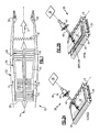
- Figure 1 schematically illustrates a gas turbine engine 10 which generally includes a fan section 12, a compressor section 14, a combustor section 16, a turbine section 18, an augmentor section 19, and a nozzle section 20.
- the compressor section 14, combustor section 16, and turbine section 18 are generally referred to as the core engine.
- An axis of the engine A is centrally disposed and extends longitudinally through these sections.
- An engine duct structure 22 and an inner cooling liner structure 24 define an annular secondary flow path 26 at least partially around a perimeter of a primary flow path 28 which directs a primary combustion core gas exhaust flow (illustrated schematically by arrow E). It should be understood that the engine duct structure 22 may also at least partially define various airflow paths other than the disclosed secondary flow path 26.
- the secondary flow path 26 guides a secondary airflow C between the engine duct structure 22 and the inner cooling liner structure 24.
- the secondary airflow as defined herein may be any airflow different from the primary combustion core gas exhaust flow E such as advent cycle third stream fan flow which may be sourced from the fan section 12 and/or compressor section 14.
- the secondary airflow C is utilized for a multiple of purposes including, for example, cooling, pressurization, partial shielding and mixing with the core gas flow E in the nozzle section 20 during particular operational profiles.
- the valve system 30 operates rapidly and repeatedly while configured to be received within minimal package space.
- a valve system 30 is located intermediate the secondary flow path 26 and the primary flow path 28 to selectively communicate secondary airflow C into the primary gas flow path E. For example only, under certain conditions, such as when an aircraft is hovering, less secondary airflow may be required in the nozzle section 20. By blocking the secondary airflow thereto, additional secondary airflow then becomes available for other purposes. It should be understood that the valve system 30 may be utilized in any location and any environment to control airflow injected from a higher pressure plenum into a lower pressure flowpath such as, for example only, in a nozzle section of a gas turbine engine.
- the valve system 30 generally includes a shaped door 32 which is pivotally mounted to a contoured frame 34 about a door axis D for movement between a closed position and an open position ( Figure 2B ).
- the shaped door 32 and contoured frame 34 are shaped to minimize airflow blockage when closed and facilitate airflow direction when open.
- the shaped door 32 and contoured frame 34 in one disclosed embodiment may be directionally shaped in a generally airfoil arrangement.
- the contoured frame 34 may be mounted to a plenum wall such as the inner cooling liner structure 24 to provide for communication between the secondary flow path 26 and the primary flow path 28.
- the contoured frame 34 at least partially surrounds an airflow path 35 ( Figure 2B ) which may further guide the airflow between the secondary flow path 26 and the primary flow path 28.
- the airflow path 35 may include a mesh, grid, metering hole or honeycomb structure which directs and smoothes the airflow therethrough as well as reduces noise generation.
- An actuator system 36 having a hydraulic, pneumatic or electromagnetic actuator 38 controls movement of the shaped door 32 through a linkage 40.
- the linkage 40 may include a seal structure 42 which may be located at the engine duct structure 22 such that the actuator 38 may be located external to the engine duct structure 22. It should be understood that various actuator systems may be usable with the present invention.
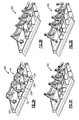
- valve system 30A includes a multitude of shaped doors 32A-32D which are pivotally mounted to a contoured frame 34A about a door axis D.
- Each of the multiple of shaped doors 32A-32D are movable between a closed position and a multiple of open positions ( Figures 3B-3D ) through an actuator system 44 which may sequentially open each of the multitude of shaped doors 32A-32D.
- One multiple of open positions are illustrated in Figures 3A-3D as an incremental opening of the multiple of shaped doors 32A-32D in a serial manner by the actuator system 44.
- Figure 3A is an illustration of a fully closed position
- Figure 3B illustrates the opening of shaped door 32A and initial opening of shaped door 32B
- Figure 3C illustrates the further opening of shaped door 32A and 32B and begins to open shaped door 32C
- Figure 3D illustrates opening of shaped doors 32A, 32B, 32C while shaped door 32D just begins to open. It should be understood that further views of this sequence would show movement of each of the shaped doors 32A-32D toward their respective fully opened position. It should be understood that this sequence of opening is but a single non-limiting embodiment and that other, different, or variable opening sequences may alternatively or additionally be provided.
- each shaped door may be individually operated rather than operated through the single actuator system 44.
- the actuator system 44 may include a crank structure which opens each of the multitude of shaped doors 32A-32D in accord with a predetermined sequence. That is, the multitude of shaped doors 32A-32D may be of different sizes and shapes to open in a sequence which communicates a predetermined volume of airflow relative to the predetermined sequence. It should be understood that essentially infinite positions may be provided. Alternatively, each of the multitude of shaped doors 32A-32D may be individually operated through independent linkages.
- Each of the multitude of shaped doors 32A-32D may be of equivalent or different size to control airflow therethrough in response to the size of the door and the degree to which each door is opened. It should be understood that other opening sequences and arrangements may alternatively or additionally be provided.
Landscapes
- Engineering & Computer Science (AREA)
- Mechanical Engineering (AREA)
- General Engineering & Computer Science (AREA)
- Chemical & Material Sciences (AREA)
- Combustion & Propulsion (AREA)
- Life Sciences & Earth Sciences (AREA)
- Sustainable Development (AREA)
- Lift Valve (AREA)
- Supercharger (AREA)
- Structures Of Non-Positive Displacement Pumps (AREA)
Applications Claiming Priority (1)
| Application Number | Priority Date | Filing Date | Title |
|---|---|---|---|
| US12/053,595 US8240126B2 (en) | 2008-03-22 | 2008-03-22 | Valve system for a gas turbine engine |
Publications (3)
| Publication Number | Publication Date |
|---|---|
| EP2103784A2 true EP2103784A2 (de) | 2009-09-23 |
| EP2103784A3 EP2103784A3 (de) | 2011-06-22 |
| EP2103784B1 EP2103784B1 (de) | 2014-08-27 |
Family
ID=40801965
Family Applications (1)
| Application Number | Title | Priority Date | Filing Date |
|---|---|---|---|
| EP09250649.2A Active EP2103784B1 (de) | 2008-03-22 | 2009-03-06 | Ventilsystem für einen Gasturbinenmotor |
Country Status (2)
| Country | Link |
|---|---|
| US (1) | US8240126B2 (de) |
| EP (1) | EP2103784B1 (de) |
Cited By (4)
| Publication number | Priority date | Publication date | Assignee | Title |
|---|---|---|---|---|
| FR2986043A1 (fr) * | 2012-01-24 | 2013-07-26 | Snecma | Conduit d'ejection comportant une trappe de drainage d'huile |
| WO2013140088A1 (fr) * | 2012-03-20 | 2013-09-26 | Aircelle | Tuyère à section variable et nacelle pour turboréacteur d'aéronef équipée d'une telle tuyère |
| EP2423495A3 (de) * | 2010-08-30 | 2015-03-18 | United Technologies Corporation | Ventilsystem für einen Gasturbinenmotor |
| FR3148254A1 (fr) * | 2023-04-26 | 2024-11-01 | Safran Aircraft Engines | Ensemble pour turbomachine d’aéronef, l’ensemble étant équipé d’un système anti-accrétion |
Families Citing this family (6)
| Publication number | Priority date | Publication date | Assignee | Title |
|---|---|---|---|---|
| US10023302B2 (en) | 2007-12-06 | 2018-07-17 | Roller Bearing Company Of America, Inc. | Actuation system for a lift assisting device and lined track rollers used therein |
| US9261132B2 (en) | 2009-04-24 | 2016-02-16 | Roller Bearing Company Of America, Inc. | Low friction bearing assembly and link apparatus |
| EP2788633A1 (de) * | 2011-12-06 | 2014-10-15 | Roller Bearing Company of America, Inc. | Verbindungsvorrichtung mit hoher taktzahl und kleinem bewegungsradius für gasturbinenmotoranwendungen |
| WO2014021958A1 (en) | 2012-04-30 | 2014-02-06 | Roller Bearing Company Of America, Inc. | Hybrid bearing assembly with rolling elements and plain bearing |
| WO2014134519A1 (en) | 2013-02-28 | 2014-09-04 | United Technologies Corporation | Method and apparatus for collecting pre-diffuser airflow and routing it to combustor pre-swirlers |
| US9605596B2 (en) | 2013-03-08 | 2017-03-28 | United Technologies Corporation | Duct blocker seal assembly for a gas turbine engine |
Citations (2)
| Publication number | Priority date | Publication date | Assignee | Title |
|---|---|---|---|---|
| US4409788A (en) | 1979-04-23 | 1983-10-18 | General Electric Company | Actuation system for use on a gas turbine engine |
| US5372006A (en) | 1993-02-08 | 1994-12-13 | Aeronautical Concept Of Exhaust, Ltd. | Turbine engine equipped with thrust reverser |
Family Cites Families (44)
| Publication number | Priority date | Publication date | Assignee | Title |
|---|---|---|---|---|
| US4711084A (en) | 1981-11-05 | 1987-12-08 | Avco Corporation | Ejector assisted compressor bleed |
| US4570668A (en) | 1984-01-16 | 1986-02-18 | Parker-Hannifin Corporation | Flow dividing valve |
| FR2569783B1 (fr) | 1984-09-06 | 1986-09-12 | Snecma | Structure d'anneau et dispositif de decharge de compresseur comportant cet anneau |
| FR2569785B1 (fr) | 1984-09-06 | 1986-09-12 | Snecma | Disposit |
| US4854127A (en) | 1988-01-14 | 1989-08-08 | General Electric Company | Bimodal swirler injector for a gas turbine combustor |
| US5127222A (en) | 1989-01-23 | 1992-07-07 | United Technologies Corporation | Buffer region for the nacelle of a gas turbine engine |
| US5012639A (en) | 1989-01-23 | 1991-05-07 | United Technologies Corporation | Buffer region for the nacelle of a gas turbine engine |
| US5123240A (en) | 1990-03-19 | 1992-06-23 | General Electric Co. | Method and apparatus for ejecting foreign matter from the primary flow path of a gas turbine engine |
| US5307624A (en) | 1990-04-04 | 1994-05-03 | General Electric Company | Variable area bypass valve assembly |
| US5184459A (en) * | 1990-05-29 | 1993-02-09 | The United States Of America As Represented By The Secretary Of The Air Force | Variable vane valve in a gas turbine |
| US5211007A (en) | 1991-04-10 | 1993-05-18 | General Electric Company | Method of pressure-ratio control of gas turbine engine |
| US6301877B1 (en) | 1995-11-13 | 2001-10-16 | United Technologies Corporation | Ejector extension cooling for exhaust nozzle |
| US5941065A (en) * | 1996-11-04 | 1999-08-24 | The Boeing Company | Stowable mixer ejection nozzle |
| US5867980A (en) | 1996-12-17 | 1999-02-09 | General Electric Company | Turbofan engine with a low pressure turbine driven supercharger in a bypass duct operated by a fuel rich combustor and an afterburner |
| US6385959B1 (en) | 1999-08-24 | 2002-05-14 | MONTOYA CéSAR AGUILERA | Gas turbine engine with increased fuel efficiency and method for accomplishing the same |
| US6264137B1 (en) | 2000-02-25 | 2001-07-24 | Honeywell International Inc. | Inlet vortex bustor and ice protector for auxiliary power units |
| US6471475B1 (en) | 2000-07-14 | 2002-10-29 | Pratt & Whitney Canada Corp. | Integrated duct diffuser |
| US6679048B1 (en) | 2000-10-24 | 2004-01-20 | Lockheed Martin Corporation | Apparatus and method for controlling primary fluid flow using secondary fluid flow injection |
| FR2823532B1 (fr) | 2001-04-12 | 2003-07-18 | Snecma Moteurs | Systeme de decharge pour turboreacteur ou turbopropulseur a commande simplifiee |
| US6868665B2 (en) | 2001-12-21 | 2005-03-22 | General Electric Company | Methods and apparatus for operating gas turbine engines |
| GB0205701D0 (en) | 2002-03-12 | 2002-04-24 | Rolls Royce Plc | Variable area nozzle |
| US6694723B2 (en) | 2002-03-27 | 2004-02-24 | United Technologies Corporation | Valve assembly for gas turbine engine |
| US6701715B2 (en) | 2002-05-02 | 2004-03-09 | Honeywell International, Inc. | Variable geometry ejector for a bleed air system using integral ejector exit pressure feedback |
| FR2840030B1 (fr) | 2002-05-21 | 2005-03-04 | Eads Launch Vehicles | Moteur a tuyere a noyau central pour lanceur spatial |
| US7028484B2 (en) | 2002-08-30 | 2006-04-18 | Pratt & Whitney Canada Corp. | Nested channel ducts for nozzle construction and the like |
| US6907724B2 (en) | 2002-09-13 | 2005-06-21 | The Boeing Company | Combined cycle engines incorporating swirl augmented combustion for reduced volume and weight and improved performance |
| US6895756B2 (en) | 2002-09-13 | 2005-05-24 | The Boeing Company | Compact swirl augmented afterburners for gas turbine engines |
| US6802691B2 (en) | 2002-11-19 | 2004-10-12 | United Technologies Corporation | Maintainable compressor stability bleed system |
| US6851255B2 (en) | 2002-12-18 | 2005-02-08 | Pratt & Whitney Canada Corp. | Normally open reverse flow flapper valve |
| US6877306B2 (en) | 2003-02-07 | 2005-04-12 | Woodward Governor Company | Nozzle assembly with flow divider and ecology valve |
| US7055329B2 (en) | 2003-03-31 | 2006-06-06 | General Electric Company | Method and apparatus for noise attenuation for gas turbine engines using at least one synthetic jet actuator for injecting air |
| US7093442B2 (en) | 2003-04-30 | 2006-08-22 | United Technologies Corporation | Augmentor |
| US7093793B2 (en) * | 2003-08-29 | 2006-08-22 | The Nordam Group, Inc. | Variable cam exhaust nozzle |
| US7395657B2 (en) | 2003-10-20 | 2008-07-08 | General Electric Company | Flade gas turbine engine with fixed geometry inlet |
| US6948317B2 (en) | 2003-10-31 | 2005-09-27 | General Electric Company | Methods and apparatus for flade engine nozzle |
| US7055303B2 (en) | 2003-12-22 | 2006-06-06 | Pratt & Whitney Canada Corp. | Gas turbine engine architecture |
| US7032835B2 (en) | 2004-01-28 | 2006-04-25 | United Technologies Corporation | Convergent/divergent nozzle with modulated cooling |
| US7305817B2 (en) | 2004-02-09 | 2007-12-11 | General Electric Company | Sinuous chevron exhaust nozzle |
| US6997676B2 (en) | 2004-03-10 | 2006-02-14 | General Electric Company | Bifurcated outlet guide vanes |
| US7174704B2 (en) | 2004-07-23 | 2007-02-13 | General Electric Company | Split shroud exhaust nozzle |
| US7475545B2 (en) * | 2005-04-29 | 2009-01-13 | General Electric Company | Fladed supersonic missile turbojet |
| US7244104B2 (en) | 2005-05-31 | 2007-07-17 | Pratt & Whitney Canada Corp. | Deflectors for controlling entry of fluid leakage into the working fluid flowpath of a gas turbine engine |
| US7189055B2 (en) | 2005-05-31 | 2007-03-13 | Pratt & Whitney Canada Corp. | Coverplate deflectors for redirecting a fluid flow |
| US7225623B2 (en) | 2005-08-23 | 2007-06-05 | General Electric Company | Trapped vortex cavity afterburner |
-
2008
- 2008-03-22 US US12/053,595 patent/US8240126B2/en active Active
-
2009
- 2009-03-06 EP EP09250649.2A patent/EP2103784B1/de active Active
Patent Citations (2)
| Publication number | Priority date | Publication date | Assignee | Title |
|---|---|---|---|---|
| US4409788A (en) | 1979-04-23 | 1983-10-18 | General Electric Company | Actuation system for use on a gas turbine engine |
| US5372006A (en) | 1993-02-08 | 1994-12-13 | Aeronautical Concept Of Exhaust, Ltd. | Turbine engine equipped with thrust reverser |
Cited By (7)
| Publication number | Priority date | Publication date | Assignee | Title |
|---|---|---|---|---|
| EP2423495A3 (de) * | 2010-08-30 | 2015-03-18 | United Technologies Corporation | Ventilsystem für einen Gasturbinenmotor |
| FR2986043A1 (fr) * | 2012-01-24 | 2013-07-26 | Snecma | Conduit d'ejection comportant une trappe de drainage d'huile |
| WO2013140088A1 (fr) * | 2012-03-20 | 2013-09-26 | Aircelle | Tuyère à section variable et nacelle pour turboréacteur d'aéronef équipée d'une telle tuyère |
| FR2988439A1 (fr) * | 2012-03-20 | 2013-09-27 | Aircelle Sa | Tuyere a section variable et nacelle pour turboreacteur d'aeronef equipee d'une telle tuyere |
| CN104204421A (zh) * | 2012-03-20 | 2014-12-10 | 埃尔塞乐公司 | 可变截面喷嘴以及装配有该喷嘴的飞机涡轮喷气发动机机舱 |
| US9850776B2 (en) | 2012-03-20 | 2017-12-26 | Aircelle | Variable-section nozzle, and aircraft turbojet engine nacelle equipped with such a nozzle |
| FR3148254A1 (fr) * | 2023-04-26 | 2024-11-01 | Safran Aircraft Engines | Ensemble pour turbomachine d’aéronef, l’ensemble étant équipé d’un système anti-accrétion |
Also Published As
| Publication number | Publication date |
|---|---|
| US20090235643A1 (en) | 2009-09-24 |
| EP2103784B1 (de) | 2014-08-27 |
| US8240126B2 (en) | 2012-08-14 |
| EP2103784A3 (de) | 2011-06-22 |
Similar Documents
| Publication | Publication Date | Title |
|---|---|---|
| EP2103784B1 (de) | Ventilsystem für einen Gasturbinenmotor | |
| US20210215120A1 (en) | Gas turbine engine bifurcation located fan variable area nozzle | |
| US9476362B2 (en) | Turbomachine with bleed valves located at the intermediate case | |
| US7818957B2 (en) | Valve assembly for a gas turbine engine | |
| US7837436B2 (en) | Method and apparatus for regulating fluid flow through a turbine engine | |
| EP1978232B1 (de) | Variable Nebenstromdüse und Schubumkehrer | |
| US8739548B2 (en) | Sliding ramp nozzle system for a gas turbine engine | |
| US20090193789A1 (en) | Variable area fan nozzle thrust reverser | |
| US10378479B2 (en) | Variable effective area fan nozzle | |
| EP2867491B1 (de) | Wartungsbetätigungssystem für eine schubumkehrvorrichtung | |
| US8075246B2 (en) | Relief device for a turbojet and a turbojet comprising same | |
| CN106968832A (zh) | 用于控制核心整流罩通风区域的方法和系统 | |
| EP2074318B1 (de) | Mantelstromtriebwerk und Verfahren zur Änderung des Austrittsquerschnitts einer Mantelstromdüse | |
| EP2074319B1 (de) | Turbinentriebwerk mit gebläsedüse mit variablem austrittquerschnitt, gondelanordnung für solch ein triebwerk und entsprechendes betriebsverfahren | |
| US8286416B2 (en) | Valve system for a gas turbine engine | |
| US8402744B2 (en) | Valve system for a gas turbine engine | |
| US20140165575A1 (en) | Nozzle section for a gas turbine engine | |
| EP2423495A2 (de) | Ventilsystem für einen Gasturbinenmotor |
Legal Events
| Date | Code | Title | Description |
|---|---|---|---|
| PUAI | Public reference made under article 153(3) epc to a published international application that has entered the european phase |
Free format text: ORIGINAL CODE: 0009012 |
|
| AK | Designated contracting states |
Kind code of ref document: A2 Designated state(s): AT BE BG CH CY CZ DE DK EE ES FI FR GB GR HR HU IE IS IT LI LT LU LV MC MK MT NL NO PL PT RO SE SI SK TR |
|
| AX | Request for extension of the european patent |
Extension state: AL BA RS |
|
| PUAL | Search report despatched |
Free format text: ORIGINAL CODE: 0009013 |
|
| AK | Designated contracting states |
Kind code of ref document: A3 Designated state(s): AT BE BG CH CY CZ DE DK EE ES FI FR GB GR HR HU IE IS IT LI LT LU LV MC MK MT NL NO PL PT RO SE SI SK TR |
|
| AX | Request for extension of the european patent |
Extension state: AL BA RS |
|
| RIC1 | Information provided on ipc code assigned before grant |
Ipc: F02K 3/06 20060101ALI20110518BHEP Ipc: F02K 3/075 20060101ALI20110518BHEP Ipc: F02K 1/30 20060101ALI20110518BHEP Ipc: F01D 17/10 20060101AFI20090708BHEP Ipc: F02K 1/38 20060101ALI20110518BHEP |
|
| 17P | Request for examination filed |
Effective date: 20111219 |
|
| AKX | Designation fees paid |
Designated state(s): DE GB |
|
| 17Q | First examination report despatched |
Effective date: 20120516 |
|
| GRAP | Despatch of communication of intention to grant a patent |
Free format text: ORIGINAL CODE: EPIDOSNIGR1 |
|
| INTG | Intention to grant announced |
Effective date: 20131029 |
|
| GRAP | Despatch of communication of intention to grant a patent |
Free format text: ORIGINAL CODE: EPIDOSNIGR1 |
|
| GRAS | Grant fee paid |
Free format text: ORIGINAL CODE: EPIDOSNIGR3 |
|
| INTG | Intention to grant announced |
Effective date: 20140324 |
|
| GRAA | (expected) grant |
Free format text: ORIGINAL CODE: 0009210 |
|
| RAP1 | Party data changed (applicant data changed or rights of an application transferred) |
Owner name: UNITED TECHNOLOGIES CORPORATION |
|
| AK | Designated contracting states |
Kind code of ref document: B1 Designated state(s): DE GB |
|
| REG | Reference to a national code |
Ref country code: GB Ref legal event code: FG4D |
|
| REG | Reference to a national code |
Ref country code: DE Ref legal event code: R096 Ref document number: 602009026257 Country of ref document: DE Effective date: 20141002 |
|
| REG | Reference to a national code |
Ref country code: DE Ref legal event code: R097 Ref document number: 602009026257 Country of ref document: DE |
|
| PLBE | No opposition filed within time limit |
Free format text: ORIGINAL CODE: 0009261 |
|
| STAA | Information on the status of an ep patent application or granted ep patent |
Free format text: STATUS: NO OPPOSITION FILED WITHIN TIME LIMIT |
|
| 26N | No opposition filed |
Effective date: 20150528 |
|
| REG | Reference to a national code |
Ref country code: DE Ref legal event code: R082 Ref document number: 602009026257 Country of ref document: DE Representative=s name: SCHMITT-NILSON SCHRAUD WAIBEL WOHLFROM PATENTA, DE |
|
| REG | Reference to a national code |
Ref country code: DE Ref legal event code: R082 Ref document number: 602009026257 Country of ref document: DE Representative=s name: SCHMITT-NILSON SCHRAUD WAIBEL WOHLFROM PATENTA, DE Ref country code: DE Ref legal event code: R081 Ref document number: 602009026257 Country of ref document: DE Owner name: UNITED TECHNOLOGIES CORP. (N.D.GES.D. STAATES , US Free format text: FORMER OWNER: UNITED TECHNOLOGIES CORP., STRATFORD, CONN., US |
|
| REG | Reference to a national code |
Ref country code: DE Ref legal event code: R081 Ref document number: 602009026257 Country of ref document: DE Owner name: RAYTHEON TECHNOLOGIES CORPORATION (N.D.GES.D.S, US Free format text: FORMER OWNER: UNITED TECHNOLOGIES CORP. (N.D.GES.D. STAATES DELAWARE), FARMINGTON, CONN., US Ref country code: DE Ref legal event code: R081 Ref document number: 602009026257 Country of ref document: DE Owner name: RTX CORPORATION (N.D.GES.D. STAATES DELAWARE),, US Free format text: FORMER OWNER: UNITED TECHNOLOGIES CORP. (N.D.GES.D. STAATES DELAWARE), FARMINGTON, CONN., US |
|
| P01 | Opt-out of the competence of the unified patent court (upc) registered |
Effective date: 20230519 |
|
| REG | Reference to a national code |
Ref country code: DE Ref legal event code: R081 Ref document number: 602009026257 Country of ref document: DE Owner name: RTX CORPORATION (N.D.GES.D. STAATES DELAWARE),, US Free format text: FORMER OWNER: RAYTHEON TECHNOLOGIES CORPORATION (N.D.GES.D.STAATES DELAWARE), ARLINGTON, VA, US |
|
| PGFP | Annual fee paid to national office [announced via postgrant information from national office to epo] |
Ref country code: GB Payment date: 20260219 Year of fee payment: 18 |
|
| PGFP | Annual fee paid to national office [announced via postgrant information from national office to epo] |
Ref country code: DE Payment date: 20260219 Year of fee payment: 18 |