EP2103531B1 - Label peeling unit and label printer - Google Patents
Label peeling unit and label printer Download PDFInfo
- Publication number
- EP2103531B1 EP2103531B1 EP07860293.5A EP07860293A EP2103531B1 EP 2103531 B1 EP2103531 B1 EP 2103531B1 EP 07860293 A EP07860293 A EP 07860293A EP 2103531 B1 EP2103531 B1 EP 2103531B1
- Authority
- EP
- European Patent Office
- Prior art keywords
- label
- movable body
- peeling
- label peeling
- mount sheet
- Prior art date
- Legal status (The legal status is an assumption and is not a legal conclusion. Google has not performed a legal analysis and makes no representation as to the accuracy of the status listed.)
- Active
Links
- 230000000717 retained effect Effects 0.000 description 5
- 238000001514 detection method Methods 0.000 description 4
- 230000031700 light absorption Effects 0.000 description 3
- 238000007599 discharging Methods 0.000 description 2
- 230000000903 blocking effect Effects 0.000 description 1
- 230000000694 effects Effects 0.000 description 1
- 238000005516 engineering process Methods 0.000 description 1
- 230000001788 irregular Effects 0.000 description 1
- 230000007257 malfunction Effects 0.000 description 1
- 238000000034 method Methods 0.000 description 1
Images

Classifications
-
- B—PERFORMING OPERATIONS; TRANSPORTING
- B65—CONVEYING; PACKING; STORING; HANDLING THIN OR FILAMENTARY MATERIAL
- B65C—LABELLING OR TAGGING MACHINES, APPARATUS, OR PROCESSES
- B65C11/00—Manually-controlled or manually-operable label dispensers, e.g. modified for the application of labels to articles
- B65C11/02—Manually-controlled or manually-operable label dispensers, e.g. modified for the application of labels to articles having printing equipment
-
- B—PERFORMING OPERATIONS; TRANSPORTING
- B41—PRINTING; LINING MACHINES; TYPEWRITERS; STAMPS
- B41J—TYPEWRITERS; SELECTIVE PRINTING MECHANISMS, i.e. MECHANISMS PRINTING OTHERWISE THAN FROM A FORME; CORRECTION OF TYPOGRAPHICAL ERRORS
- B41J11/00—Devices or arrangements of selective printing mechanisms, e.g. ink-jet printers or thermal printers, for supporting or handling copy material in sheet or web form
- B41J11/0025—Handling copy materials differing in width
-
- B—PERFORMING OPERATIONS; TRANSPORTING
- B41—PRINTING; LINING MACHINES; TYPEWRITERS; STAMPS
- B41J—TYPEWRITERS; SELECTIVE PRINTING MECHANISMS, i.e. MECHANISMS PRINTING OTHERWISE THAN FROM A FORME; CORRECTION OF TYPOGRAPHICAL ERRORS
- B41J15/00—Devices or arrangements of selective printing mechanisms, e.g. ink-jet printers or thermal printers, specially adapted for supporting or handling copy material in continuous form, e.g. webs
- B41J15/04—Supporting, feeding, or guiding devices; Mountings for web rolls or spindles
- B41J15/042—Supporting, feeding, or guiding devices; Mountings for web rolls or spindles for loading rolled-up continuous copy material into printers, e.g. for replacing a used-up paper roll; Point-of-sale printers with openable casings allowing access to the rolled-up continuous copy material
-
- B—PERFORMING OPERATIONS; TRANSPORTING
- B41—PRINTING; LINING MACHINES; TYPEWRITERS; STAMPS
- B41J—TYPEWRITERS; SELECTIVE PRINTING MECHANISMS, i.e. MECHANISMS PRINTING OTHERWISE THAN FROM A FORME; CORRECTION OF TYPOGRAPHICAL ERRORS
- B41J29/00—Details of, or accessories for, typewriters or selective printing mechanisms not otherwise provided for
- B41J29/02—Framework
-
- B—PERFORMING OPERATIONS; TRANSPORTING
- B41—PRINTING; LINING MACHINES; TYPEWRITERS; STAMPS
- B41J—TYPEWRITERS; SELECTIVE PRINTING MECHANISMS, i.e. MECHANISMS PRINTING OTHERWISE THAN FROM A FORME; CORRECTION OF TYPOGRAPHICAL ERRORS
- B41J3/00—Typewriters or selective printing or marking mechanisms characterised by the purpose for which they are constructed
- B41J3/407—Typewriters or selective printing or marking mechanisms characterised by the purpose for which they are constructed for marking on special material
- B41J3/4075—Tape printers; Label printers
-
- B—PERFORMING OPERATIONS; TRANSPORTING
- B65—CONVEYING; PACKING; STORING; HANDLING THIN OR FILAMENTARY MATERIAL
- B65C—LABELLING OR TAGGING MACHINES, APPARATUS, OR PROCESSES
- B65C9/00—Details of labelling machines or apparatus
- B65C9/0006—Removing backing sheets
-
- B—PERFORMING OPERATIONS; TRANSPORTING
- B65—CONVEYING; PACKING; STORING; HANDLING THIN OR FILAMENTARY MATERIAL
- B65H—HANDLING THIN OR FILAMENTARY MATERIAL, e.g. SHEETS, WEBS, CABLES
- B65H37/00—Article or web delivery apparatus incorporating devices for performing specified auxiliary operations
- B65H37/002—Web delivery apparatus, the web serving as support for articles, material or another web
-
- B—PERFORMING OPERATIONS; TRANSPORTING
- B65—CONVEYING; PACKING; STORING; HANDLING THIN OR FILAMENTARY MATERIAL
- B65H—HANDLING THIN OR FILAMENTARY MATERIAL, e.g. SHEETS, WEBS, CABLES
- B65H41/00—Machines for separating superposed webs
-
- B—PERFORMING OPERATIONS; TRANSPORTING
- B65—CONVEYING; PACKING; STORING; HANDLING THIN OR FILAMENTARY MATERIAL
- B65H—HANDLING THIN OR FILAMENTARY MATERIAL, e.g. SHEETS, WEBS, CABLES
- B65H2701/00—Handled material; Storage means
- B65H2701/10—Handled articles or webs
- B65H2701/19—Specific article or web
- B65H2701/194—Web supporting regularly spaced adhesive articles, e.g. labels, rubber articles, labels or stamps
-
- Y—GENERAL TAGGING OF NEW TECHNOLOGICAL DEVELOPMENTS; GENERAL TAGGING OF CROSS-SECTIONAL TECHNOLOGIES SPANNING OVER SEVERAL SECTIONS OF THE IPC; TECHNICAL SUBJECTS COVERED BY FORMER USPC CROSS-REFERENCE ART COLLECTIONS [XRACs] AND DIGESTS
- Y10—TECHNICAL SUBJECTS COVERED BY FORMER USPC
- Y10T—TECHNICAL SUBJECTS COVERED BY FORMER US CLASSIFICATION
- Y10T156/00—Adhesive bonding and miscellaneous chemical manufacture
- Y10T156/11—Methods of delaminating, per se; i.e., separating at bonding face
- Y10T156/1168—Gripping and pulling work apart during delaminating
- Y10T156/1174—Using roller for delamination [e.g., roller pairs operating at differing speeds or directions, etc.]
-
- Y—GENERAL TAGGING OF NEW TECHNOLOGICAL DEVELOPMENTS; GENERAL TAGGING OF CROSS-SECTIONAL TECHNOLOGIES SPANNING OVER SEVERAL SECTIONS OF THE IPC; TECHNICAL SUBJECTS COVERED BY FORMER USPC CROSS-REFERENCE ART COLLECTIONS [XRACs] AND DIGESTS
- Y10—TECHNICAL SUBJECTS COVERED BY FORMER USPC
- Y10T—TECHNICAL SUBJECTS COVERED BY FORMER US CLASSIFICATION
- Y10T156/00—Adhesive bonding and miscellaneous chemical manufacture
- Y10T156/11—Methods of delaminating, per se; i.e., separating at bonding face
- Y10T156/1168—Gripping and pulling work apart during delaminating
- Y10T156/1195—Delaminating from release surface
-
- Y—GENERAL TAGGING OF NEW TECHNOLOGICAL DEVELOPMENTS; GENERAL TAGGING OF CROSS-SECTIONAL TECHNOLOGIES SPANNING OVER SEVERAL SECTIONS OF THE IPC; TECHNICAL SUBJECTS COVERED BY FORMER USPC CROSS-REFERENCE ART COLLECTIONS [XRACs] AND DIGESTS
- Y10—TECHNICAL SUBJECTS COVERED BY FORMER USPC
- Y10T—TECHNICAL SUBJECTS COVERED BY FORMER US CLASSIFICATION
- Y10T156/00—Adhesive bonding and miscellaneous chemical manufacture
- Y10T156/19—Delaminating means
- Y10T156/195—Delaminating roller means
-
- Y—GENERAL TAGGING OF NEW TECHNOLOGICAL DEVELOPMENTS; GENERAL TAGGING OF CROSS-SECTIONAL TECHNOLOGIES SPANNING OVER SEVERAL SECTIONS OF THE IPC; TECHNICAL SUBJECTS COVERED BY FORMER USPC CROSS-REFERENCE ART COLLECTIONS [XRACs] AND DIGESTS
- Y10—TECHNICAL SUBJECTS COVERED BY FORMER USPC
- Y10T—TECHNICAL SUBJECTS COVERED BY FORMER US CLASSIFICATION
- Y10T156/00—Adhesive bonding and miscellaneous chemical manufacture
- Y10T156/19—Delaminating means
- Y10T156/1978—Delaminating bending means
-
- Y—GENERAL TAGGING OF NEW TECHNOLOGICAL DEVELOPMENTS; GENERAL TAGGING OF CROSS-SECTIONAL TECHNOLOGIES SPANNING OVER SEVERAL SECTIONS OF THE IPC; TECHNICAL SUBJECTS COVERED BY FORMER USPC CROSS-REFERENCE ART COLLECTIONS [XRACs] AND DIGESTS
- Y10—TECHNICAL SUBJECTS COVERED BY FORMER USPC
- Y10T—TECHNICAL SUBJECTS COVERED BY FORMER US CLASSIFICATION
- Y10T156/00—Adhesive bonding and miscellaneous chemical manufacture
- Y10T156/19—Delaminating means
- Y10T156/1994—Means for delaminating from release surface
Definitions
- the present invention relates to a label peeling unit that is fitted to a label printer or the like that conveys a continuous label strip in which labels are adhered removably on a mount sheet and performs printing on the labels, and is used for peeling the labels from the mount sheet.
- the invention also relates to a label printer to which such a label peeling unit is fitted.
- a continuous label strip (hereinafter also referred to as a "paper sheet") in which labels with a predetermined length are adhered removably to a long strip-shaped mount sheet (separator) at regular intervals, for example, is used as a print medium.
- the paper sheet is conveyed by platen rollers, and the labels are printed using a thermal head provided so as to oppose the platen rollers across the paper sheet.
- printed labels are automatically peeled off from the mount sheet using a label peeling mechanism (label peeling unit).
- Patent Document 1 a paper label peeling apparatus that can be fitted to an existing thermal printer is disclosed in Patent Document 1 shown below.
- a pressure roller, a feed roller, and a capstan roller are rotatably supported onto a frame by shafts.
- the pressure roller and the feed roller are coupled to each other by a gear, and the feed roller and the capstan roller are brought into contact with each other by an appropriate pressing force.
- a peeling part is provided so as to oppose the feed roller, and the pressure roller is in contact with a platen of the thermal printer.
- This paper label peeling apparatus makes it possible to use an existing thermal printer as a label printer. Moreover, it is described that it is possible to drive the paper label peeling apparatus without necessitating a dedicated drive source, such as a motor, or a control circuit by firmware.
- a problem with the paper label peeling apparatus of Patent Document 1 is that it is difficult to insert the paper sheet through the paper label peeling apparatus because the locations of the peeling part for peeling labels and the rollers for conveying the paper sheet are close to each other.
- Patent Document 1 JP-A-7-132919 (p. 1, Fig. 1 )
- the invention provides a label peeling unit according to claim 1, which peeling unit is fitted to a paper sheet conveying device for conveying a continuous label strip in which labels are adhered removably on a mount sheet, and used for peeling the labels, the label peeling unit comprising: an attachment body attached to a case of the paper sheet conveying device; a movable body being movable while engaging with the attachment body, the movable body being urged by a spring, whereby it stops in a closed state or in an open state with respect to the attachment body; a label peeling body, fitted to the movable body and contacted by the mount sheet of the continuous label strip conveyed by the paper sheet conveying device so that the mount sheet is bent, to thereby peel a portion of a label from the mount sheet; and a mount sheet conveying roller, attached to the movable body freely rotatably, and rotating while being in contact with a platen roller of the paper sheet conveying
- the invention provides a label printer according to claim 5, for conveying a continuous label strip in which labels are adhered removably to a mount sheet, and performing printing on the labels
- the label printer comprising: a case in which an enclosing unit for enclosing a continuous label strip coiled in a roll form is formed; a platen roller being rotated and driven by a motor provided in the case, to thereby convey the continuous label strip; a print head for printing on labels while sandwiching the continuous label strip between it and the platen roller; a front face cover attached openably/closably to the case; and a label peeling unit according to the invention, attached to the case within the front face cover.
- a label peeling body for peeling labels and a mount sheet conveying roller for conveying a mount sheet and discharging it outside are mounted to a movable body that is capable of parallel shifting and rotational shifting relative to an attachment body. Therefore, inserting of paper sheets is made easy in the label peeling unit.
- the label peeling unit according to the invention is used by being fitted in a label printer or the like in which a continuous label strip is conveyed and the labels are printed, or in a peeling device for conveying a continuous label strip and peeling the labels (these devices are referred to as "paper sheet conveying devices" in the present application).
- a peeling device for conveying a continuous label strip and peeling the labels (these devices are referred to as "paper sheet conveying devices" in the present application).
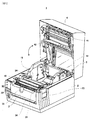
- Fig. 1 is a perspective view showing the outline of a label printer in which a label peeling unit according to one embodiment of the invention is fitted.
- a label printer 1 comprises a case 2, a paper sheet retaining mechanism 5 for freely rotatably retaining a paper roll in which a continuous label strip (paper sheet) is coiled in roll form, a platen roller 18 for conveying the paper sheet, a label sensor 19 for detecting the location of a label, and a front face cover 3 and an upper face cover 4 that are attached pivotably relative to the case 2, in the direction shown by the arrow.
- a peeling roller 31 for pressing the surface of a paper sheet downward is attached rotatably to the front face cover 3, and in addition, the front face cover 3 is provided with a display unit 32 such as LEDs, an operation unit33 such as operation keys, and a mount sheet discharge port 34 for discharging a mount sheet.
- a recessed portion 35 is formed in at least a portion of the front face cover 3 so that the labels can be easily removed.
- a thermal head 41 and a detection protrusion 42 are attached to the upper face cover 4, and the upper face cover 4 is provided with a transparent window 43 for confirming the condition of the paper sheets.
- the case 2 is provided with a cover-open/close lever 23 for opening/closing the upper face cover 4, and a cover-open/close sensor 24 for detecting opening/closure of the upper face cover 4.
- the cover-open/close sensor 24 includes a light-emitting element and a photodetector element. Because of blocking of light by the detection protrusion 42, it can detect that the upper face cover 4 is closed, so it is possible to prevent the printing operation from being performed when the upper face cover 4 is kept open (i.e., when the upper face cover 4 is not closed completely).
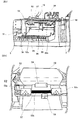
- Fig. 2 is a plan view showing the structure of the main unit side of the label printer shown in Fig. 1 .
- the paper sheet retaining mechanism 5 is installed in the paper roll enclosing recess 2a so as to retain the paper roll 20r freely rotatably.
- two paper sheet side face guides 6 for restricting the location of the paper roll 20r along the width direction (shaft direction) are provided so that the locations thereof can be varied according to the width of the paper sheet.
- a paper sheet upper face guide 6a is formed integrally with at least one of the paper sheet side face guides 6. The paper sheet upper face guide 6a prevents fluttering of the paper sheet by pressing a widthwise end portion of the continuous label strip 20 that has been pulled out from the paper roll 20r downwardly, so as to make better the detection operation of the label sensor 19 (see Fig. 1 ), disposed at an opposite location across the continuous label strip 20.
- Sliding members 11 along the widthwise direction of the paper roll 20r are provided integrally with the lower ends of the paper sheet side face guides 6, and these sliding members 11 are fitted respectively in a pair of guide grooves 12, which are formed in the bottom face of the paper roll enclosing recess 2a, freely slidably.
- the two paper sheet side face guides 6 are allowed to be capable of shifting in the directions in which they approach each other or move away from each other, while keeping the parallel condition.
- Two racks 13 are provided respectively for the two paper sheet side face guides 6, along the bottom face of the paper roll enclosing recess 2a, and a pinion 14 that meshes with these racks 13 is provided freely rotatably at a location at which the racks 13 face each other.
- a pinion 14 that meshes with these racks 13 is provided freely rotatably at a location at which the racks 13 face each other.
- a platen roller retaining portion 17 is attached to the case 2, and two platen roller bearings 18a are retained by the platen roller retaining portion 17, and the platen roller 18 is retained rotatably by these platen roller bearings 18a.
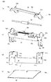
- FIG. 3 is a perspective view showing the label peeling unit in the state in which the front face cover of the label printer shown in Fig. 1 is open.
- a label peeling unit 50 has an attachment body 51 attached to the case 2 of the label printer by screw-fastening, a movable body 52 retained in such a condition as to be capable of parallel shifting and rotational shifting while engaging with the attachment body 51, a label peeling body 53 attached rotatably to the movable body 52, a mount sheet conveying roller 54 that is attached freely rotatably to the movable body 52 and is driven-rotated by making contact with the platen roller 18, which is rotation-driven by a motor that is not shown in the drawing, and a guide plate 55 located below the movable body 52 and attached freely rotatably to the attachment body 51.
- the movable body 52 By being urged by a spring, the movable body 52 can stop either in a closed state or in an open state with respect to the attachment body 51.
- the movable body 52 In Fig. 3 , the movable body 52 is in a closed state with respect to the attachment body 51.
- At least one pressing part that is pressed down when shifting the movable body 52 is provided integrally with the movable body 52.
- two pressing parts 52a are shown. By pressing down the pressing parts 52a toward the attachment body 51 side, the movable body 52 can be opened frontward.
- Fig. 4 is a view showing the state in which the front face cover and the movable body are open to insert a paper sheet.
- the mount sheet conveying roller 54 that has been in contact with the platen roller 18 can be separated from the platen roller 18, so it becomes possible to insert a paper sheet through the label peeling unit.
- the inserted continuous label strip 20 is folded over at the fore-end of the label peeling body 53 and is thereby bent considerably.
- the movable body 52 is closed by pressing the pressing part 52a toward the label printer side after inserting the paper sheet.
- the peeling roller 31 shifts above the label peeling body 53 ( Fig. 3 ) and presses the paper sheet in a direction toward the label peeling body 53 (downward) at a location opposite to the label peeling body 53.
- a label is peeled off from the mount sheet at the time when the paper sheet passes through the bent portion, and the conveying of the paper sheet is temporarily stopped in the state in which a portion of the label is removably adhered on the mount sheet and retained on the label peeling body 53.
- a peeling sensor 56 secured to the movable body 52 is used to detect whether or not the label has been removed.
- a light absorption part 52b for absorbing light is formed in the movable body 52 in order to prevent malfunctions of the peeling sensor 56 resulting from the entry of extraneous light or the irregular reflection of light.
- the next label is not issued.
- the next label is printed and conveyed to the label peeling unit 50.
- the recessed portion 35 for making removal of the label easy is formed in at least a portion of the front face cover 3. Therefore, the label can be removed easily by inserting a finger into the recessed portion 35, even if the label has a short length along the conveyance direction.
- Figs. 5(a) through 5(e) and Figs. 6(a) and (b) are perspective views showing a plurality of component parts of the label peeling unit
- Fig. 7 is a perspective view showing the structure of the label peeling unit assembled using the component parts.
- the attachment body 51 has a plurality of screw holes 51a formed therein and used when attached to the case of the label printer, two screw holes 51b formed therein and used for attaching the movable body 52, two engaging grooves 51c for engaging respectively with two engaging protrusions 52d (see Fig. 5(c) ) of the movable body 52, two mounting holes 51d for attaching the guide plate 55 thereto, and an engaging piece 51e for engaging with one end of an extension spring 61.
- the movable body 52 has the two pressing parts 52a on which a plurality of protruding portions are formed thereon as non-slip parts, the light absorption part 52b for absorbing light, two elongated holes 52c for attaching the movable body 52 slidably to screws (not shown) attached to the screw holes 51b of the attachment body 51, two engaging protrusions 52d protruding inwardly so as to engage respectively with the two engaging grooves 51c of the attachment body 51, shaft holes 52e for inserting the shaft of the mount sheet conveying roller 54 (see Fig. 5(b) ), and an engaging piece 52f for engaging with the other end of the extension spring 61.
- the label peeling body 53 has shaft grooves 53a formed therein for inserting the shaft of the mount sheet conveying roller 54, protruding portions 53b formed thereon, and inclined surfaces 53c formed thereon.
- the guide plate 55 has mounting pieces 55a formed thereon.
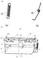
- the extension spring 61 shown in Fig. 6(a) is hooked between the engaging piece 51e of the attachment body 51 and the engaging piece 52f of the movable body 52 so as to urge the movable body 52 toward the attachment body 51 side (upward) .
- a torsion spring 62 shown in Fig. 6 (b) is retained by the shaft of the mount sheet conveying roller 54, so as to urge the label peeling body 53 in a direction away from the movable body 52 (upward).
- mount screws are inserted in the screw holes 51b of the attachment body 51 through the elongated holes 52c of the movable body 52.
- the engaging protrusions 52d of the movable body 52 engage with the engaging grooves 51c of the attachment body 51.
- the movable body 52 can perform parallel shifting and rotational shifting relative to the attachment body 51.
- the engaging protrusions 52d are positioned in upper portions of the L-shaped engaging grooves 51c by the tension of the extension spring 61, and the movable body 52 is in a closed state with respect to the attachment body 51.
- the movable body 52 By pressing down the pressing parts 52a by the operator, the engaging protrusions 52d move to lower portions of the L-shaped engaging grooves 51c, the movable body 52 pivots by the tension of the extension spring 61, and the engaging protrusions 52d move to the front ends of the lower portions of the L-shaped engaging grooves 51c. Thereby, the movable body 52 opens frontward. As a result, the gap between the platen roller 18 and the mount sheet conveying roller 54 supported by the movable body 52 is widened, so inserting a paper sheet through the label peeling unit becomes easy. When the operator presses the pressing parts 52a toward the label printer side after inserting the paper sheet, the movable body 52 closes again.
- the shaft of the mount sheet conveying roller 54 is inserted through the shaft holes 52e of the movable body 52, the shaft grooves 53a of the label peeling body 53, and the torsion spring 62.
- the mount sheet conveying roller 54 is attached freely rotatably to the movable body 52
- the label peeling body 53 is attached rotatably to the movable body 52 taking the shaft of the mount sheet conveying roller 54 as the axis of rotation.
- the label peeling body 53 is urged upwardly (in the opposite direction to the moving direction of the mount sheet) by the torsion spring 62.
- the mount sheet conveying roller 54 rotates by making contact with the platen roller via a paper sheet so that it conveys the mount sheet and discharges it outside.
- both ends of the peeling roller 31 move along the inclined surfaces 53c of the label peeling body 53 and resist the upward force by the torsion spring 62.
- the protruding portions 53b of the label peeling body 53 comes into contact with the platen roller retaining portion 17 (see Fig. 3 ), so the pivoting movement by the torsion spring 62 is restricted.
- the guide plate 55 is attached freely rotatably to the attachment body 51. The guide plate 55 guides the discharged mount sheet toward the mount sheet discharge port 34 (see Fig. 1 ).
Landscapes
- Labeling Devices (AREA)
- Folding Of Thin Sheet-Like Materials, Special Discharging Devices, And Others (AREA)
- Accessory Devices And Overall Control Thereof (AREA)
Description
- The present invention relates to a label peeling unit that is fitted to a label printer or the like that conveys a continuous label strip in which labels are adhered removably on a mount sheet and performs printing on the labels, and is used for peeling the labels from the mount sheet. The invention also relates to a label printer to which such a label peeling unit is fitted.
- In a label printer, a continuous label strip (hereinafter also referred to as a "paper sheet") in which labels with a predetermined length are adhered removably to a long strip-shaped mount sheet (separator) at regular intervals, for example, is used as a print medium. The paper sheet is conveyed by platen rollers, and the labels are printed using a thermal head provided so as to oppose the platen rollers across the paper sheet. Moreover, in some cases, printed labels are automatically peeled off from the mount sheet using a label peeling mechanism (label peeling unit).
- Such a printer with a peeling unit according to the preamble of
claim 1 is disclosed inUS 6766844 B1 . - As a related technology, a paper label peeling apparatus that can be fitted to an existing thermal printer is disclosed in
Patent Document 1 shown below. In this paper label peeling apparatus, a pressure roller, a feed roller, and a capstan roller are rotatably supported onto a frame by shafts. The pressure roller and the feed roller are coupled to each other by a gear, and the feed roller and the capstan roller are brought into contact with each other by an appropriate pressing force. A peeling part is provided so as to oppose the feed roller, and the pressure roller is in contact with a platen of the thermal printer. This paper label peeling apparatus makes it possible to use an existing thermal printer as a label printer. Moreover, it is described that it is possible to drive the paper label peeling apparatus without necessitating a dedicated drive source, such as a motor, or a control circuit by firmware. - A problem with the paper label peeling apparatus of
Patent Document 1, however, is that it is difficult to insert the paper sheet through the paper label peeling apparatus because the locations of the peeling part for peeling labels and the rollers for conveying the paper sheet are close to each other. - [Patent Document 1]
JP-A-7-132919 Fig. 1 ) - In view of the foregoing point, it is an object of the invention to make easy inserting of paper sheets in a label peeling unit fitted to a label printer or the like and used for peeling labels from a mount sheet. It is also an object of the invention to provide a label printer in which such a label peeling unit is fitted.
- In order to solve the foregoing problems, the invention provides a label peeling unit according to
claim 1, which peeling unit is fitted to a paper sheet conveying device for conveying a continuous label strip in which labels are adhered removably on a mount sheet, and used for peeling the labels, the label peeling unit comprising: an attachment body attached to a case of the paper sheet conveying device; a movable body being movable while engaging with the attachment body, the movable body being urged by a spring, whereby it stops in a closed state or in an open state with respect to the attachment body; a label peeling body, fitted to the movable body and contacted by the mount sheet of the continuous label strip conveyed by the paper sheet conveying device so that the mount sheet is bent, to thereby peel a portion of a label from the mount sheet; and a mount sheet conveying roller, attached to the movable body freely rotatably, and rotating while being in contact with a platen roller of the paper sheet conveying - device via the mount sheet, to thereby convey the mount sheet and discharge it outside.
- In another aspect, the invention provides a label printer according to
claim 5, for conveying a continuous label strip in which labels are adhered removably to a mount sheet, and performing printing on the labels, the label printer comprising: a case in which an enclosing unit for enclosing a continuous label strip coiled in a roll form is formed; a platen roller being rotated and driven by a motor provided in the case, to thereby convey the continuous label strip; a print head for printing on labels while sandwiching the continuous label strip between it and the platen roller; a front face cover attached openably/closably to the case; and a label peeling unit according to the invention, attached to the case within the front face cover. - According to the invention, a label peeling body for peeling labels and a mount sheet conveying roller for conveying a mount sheet and discharging it outside are mounted to a movable body that is capable of parallel shifting and rotational shifting relative to an attachment body. Therefore, inserting of paper sheets is made easy in the label peeling unit.
- Hereinbelow, embodiments of the invention will be described with reference to the drawings. It should be noted that the same component parts are designated by the same reference numerals, and the explanations thereof will be omitted.
- The label peeling unit according to the invention is used by being fitted in a label printer or the like in which a continuous label strip is conveyed and the labels are printed, or in a peeling device for conveying a continuous label strip and peeling the labels (these devices are referred to as "paper sheet conveying devices" in the present application). The following embodiments, however, describes the cases in which the label peeling unit is fitted and used in the label printer.
-
Fig. 1 is a perspective view showing the outline of a label printer in which a label peeling unit according to one embodiment of the invention is fitted. As shown inFig. 1 , alabel printer 1 comprises acase 2, a papersheet retaining mechanism 5 for freely rotatably retaining a paper roll in which a continuous label strip (paper sheet) is coiled in roll form, aplaten roller 18 for conveying the paper sheet, alabel sensor 19 for detecting the location of a label, and afront face cover 3 and an upper face cover 4 that are attached pivotably relative to thecase 2, in the direction shown by the arrow. - A
peeling roller 31 for pressing the surface of a paper sheet downward is attached rotatably to thefront face cover 3, and in addition, thefront face cover 3 is provided with adisplay unit 32 such as LEDs, an operation unit33 such as operation keys, and a mountsheet discharge port 34 for discharging a mount sheet. Arecessed portion 35 is formed in at least a portion of thefront face cover 3 so that the labels can be easily removed. - A
thermal head 41 and adetection protrusion 42 are attached to the upper face cover 4, and the upper face cover 4 is provided with atransparent window 43 for confirming the condition of the paper sheets. - The
case 2 is provided with a cover-open/close lever 23 for opening/closing the upper face cover 4, and a cover-open/close sensor 24 for detecting opening/closure of the upper face cover 4. The cover-open/close sensor 24 includes a light-emitting element and a photodetector element. Because of blocking of light by thedetection protrusion 42, it can detect that the upper face cover 4 is closed, so it is possible to prevent the printing operation from being performed when the upper face cover 4 is kept open (i.e., when the upper face cover 4 is not closed completely). -
Fig. 2 is a plan view showing the structure of the main unit side of the label printer shown inFig. 1 . A paperroll enclosing recess 2a for enclosing apaper roll 20r, in which acontinuous label strip 20 is coiled in roll form, is formed in thecase 2. The papersheet retaining mechanism 5 is installed in the paperroll enclosing recess 2a so as to retain thepaper roll 20r freely rotatably. - In the paper
sheet retaining mechanism 5, two paper sheetside face guides 6 for restricting the location of thepaper roll 20r along the width direction (shaft direction) are provided so that the locations thereof can be varied according to the width of the paper sheet. In addition, a paper sheetupper face guide 6a is formed integrally with at least one of the paper sheetside face guides 6. The paper sheetupper face guide 6a prevents fluttering of the paper sheet by pressing a widthwise end portion of thecontinuous label strip 20 that has been pulled out from thepaper roll 20r downwardly, so as to make better the detection operation of the label sensor 19 (seeFig. 1 ), disposed at an opposite location across thecontinuous label strip 20. - Sliding
members 11 along the widthwise direction of thepaper roll 20r are provided integrally with the lower ends of the paper sheetside face guides 6, and these slidingmembers 11 are fitted respectively in a pair ofguide grooves 12, which are formed in the bottom face of the paperroll enclosing recess 2a, freely slidably. Thereby, the two paper sheetside face guides 6 are allowed to be capable of shifting in the directions in which they approach each other or move away from each other, while keeping the parallel condition. - Two
racks 13 are provided respectively for the two paper sheetside face guides 6, along the bottom face of the paperroll enclosing recess 2a, and apinion 14 that meshes with theseracks 13 is provided freely rotatably at a location at which the racks 13 face each other. As a result, when one of the paper sheetside face guides 6 is shifted a certain distance in a desired direction, the other one of the paper sheetside face guides 6 also shifts by the same distance in the opposite direction. An engaging protrusion (not shown) provided on the paper sheetside face guide 6 engages with an engaging groove (not shown) provided in the paperroll enclosing recess 2a, whereby the widthwise locations of the paper sheetside face guides 6 are determined. - In addition, a platen
roller retaining portion 17 is attached to thecase 2, and twoplaten roller bearings 18a are retained by the platenroller retaining portion 17, and theplaten roller 18 is retained rotatably by theseplaten roller bearings 18a. -
Fig. 3 is a perspective view showing the label peeling unit in the state in which the front face cover of the label printer shown inFig. 1 is open. Alabel peeling unit 50 has anattachment body 51 attached to thecase 2 of the label printer by screw-fastening, amovable body 52 retained in such a condition as to be capable of parallel shifting and rotational shifting while engaging with theattachment body 51, alabel peeling body 53 attached rotatably to themovable body 52, a mountsheet conveying roller 54 that is attached freely rotatably to themovable body 52 and is driven-rotated by making contact with theplaten roller 18, which is rotation-driven by a motor that is not shown in the drawing, and aguide plate 55 located below themovable body 52 and attached freely rotatably to theattachment body 51. - By being urged by a spring, the
movable body 52 can stop either in a closed state or in an open state with respect to theattachment body 51. InFig. 3 , themovable body 52 is in a closed state with respect to theattachment body 51. At least one pressing part that is pressed down when shifting themovable body 52 is provided integrally with themovable body 52. InFig. 3 , twopressing parts 52a are shown. By pressing down thepressing parts 52a toward theattachment body 51 side, themovable body 52 can be opened frontward. -
Fig. 4 is a view showing the state in which the front face cover and the movable body are open to insert a paper sheet. By opening themovable body 52 frontward, the mountsheet conveying roller 54 that has been in contact with theplaten roller 18 can be separated from theplaten roller 18, so it becomes possible to insert a paper sheet through the label peeling unit. As shown inFig. 4 , the insertedcontinuous label strip 20 is folded over at the fore-end of thelabel peeling body 53 and is thereby bent considerably. Themovable body 52 is closed by pressing thepressing part 52a toward the label printer side after inserting the paper sheet. Moreover, by closing thefront face cover 3 as shown inFig. 1 , thepeeling roller 31 shifts above the label peeling body 53 (Fig. 3 ) and presses the paper sheet in a direction toward the label peeling body 53 (downward) at a location opposite to thelabel peeling body 53. - When a paper sheet is conveyed under this condition, a label is peeled off from the mount sheet at the time when the paper sheet passes through the bent portion, and the conveying of the paper sheet is temporarily stopped in the state in which a portion of the label is removably adhered on the mount sheet and retained on the
label peeling body 53. Also, apeeling sensor 56 secured to themovable body 52 is used to detect whether or not the label has been removed. Alight absorption part 52b for absorbing light is formed in themovable body 52 in order to prevent malfunctions of the peelingsensor 56 resulting from the entry of extraneous light or the irregular reflection of light. - While the peeling
sensor 56 is detecting the label, the next label is not issued. When the peeled label is removed by the operator or the like and the peelingsensor 56 no longer detects the label, the next label is printed and conveyed to thelabel peeling unit 50. As shown inFig. 1 , the recessedportion 35 for making removal of the label easy is formed in at least a portion of thefront face cover 3. Therefore, the label can be removed easily by inserting a finger into the recessedportion 35, even if the label has a short length along the conveyance direction. -
Figs. 5(a) through 5(e) andFigs. 6(a) and (b) are perspective views showing a plurality of component parts of the label peeling unit, andFig. 7 is a perspective view showing the structure of the label peeling unit assembled using the component parts. As shown inFig. 5(d) , theattachment body 51 has a plurality ofscrew holes 51a formed therein and used when attached to the case of the label printer, twoscrew holes 51b formed therein and used for attaching themovable body 52, two engaginggrooves 51c for engaging respectively with two engagingprotrusions 52d (seeFig. 5(c) ) of themovable body 52, two mountingholes 51d for attaching theguide plate 55 thereto, and anengaging piece 51e for engaging with one end of anextension spring 61. - As shown in
Fig. 5(c) , themovable body 52 has the twopressing parts 52a on which a plurality of protruding portions are formed thereon as non-slip parts, thelight absorption part 52b for absorbing light, twoelongated holes 52c for attaching themovable body 52 slidably to screws (not shown) attached to the screw holes 51b of theattachment body 51, two engagingprotrusions 52d protruding inwardly so as to engage respectively with the twoengaging grooves 51c of theattachment body 51,shaft holes 52e for inserting the shaft of the mount sheet conveying roller 54 (seeFig. 5(b) ), and anengaging piece 52f for engaging with the other end of theextension spring 61. - As shown in
Fig. 5(a) , thelabel peeling body 53 hasshaft grooves 53a formed therein for inserting the shaft of the mountsheet conveying roller 54, protrudingportions 53b formed thereon, andinclined surfaces 53c formed thereon. As shown inFig. 5(e) , theguide plate 55 has mountingpieces 55a formed thereon. - The
extension spring 61 shown inFig. 6(a) is hooked between theengaging piece 51e of theattachment body 51 and theengaging piece 52f of themovable body 52 so as to urge themovable body 52 toward theattachment body 51 side (upward) . Atorsion spring 62 shown inFig. 6 (b) is retained by the shaft of the mountsheet conveying roller 54, so as to urge thelabel peeling body 53 in a direction away from the movable body 52 (upward). - Referring to
Figs. 5 to 7 , mount screws are inserted in the screw holes 51b of theattachment body 51 through theelongated holes 52c of themovable body 52. At the same time, the engagingprotrusions 52d of themovable body 52 engage with the engaginggrooves 51c of theattachment body 51. Thus, themovable body 52 can perform parallel shifting and rotational shifting relative to theattachment body 51. In the state shown inFig. 7 , the engagingprotrusions 52d are positioned in upper portions of the L-shapedengaging grooves 51c by the tension of theextension spring 61, and themovable body 52 is in a closed state with respect to theattachment body 51. - By pressing down the
pressing parts 52a by the operator, the engagingprotrusions 52d move to lower portions of the L-shapedengaging grooves 51c, themovable body 52 pivots by the tension of theextension spring 61, and the engagingprotrusions 52d move to the front ends of the lower portions of the L-shapedengaging grooves 51c. Thereby, themovable body 52 opens frontward. As a result, the gap between theplaten roller 18 and the mountsheet conveying roller 54 supported by themovable body 52 is widened, so inserting a paper sheet through the label peeling unit becomes easy. When the operator presses thepressing parts 52a toward the label printer side after inserting the paper sheet, themovable body 52 closes again. - The shaft of the mount
sheet conveying roller 54 is inserted through the shaft holes 52e of themovable body 52, theshaft grooves 53a of thelabel peeling body 53, and thetorsion spring 62. Thereby, the mountsheet conveying roller 54 is attached freely rotatably to themovable body 52, and thelabel peeling body 53 is attached rotatably to themovable body 52 taking the shaft of the mountsheet conveying roller 54 as the axis of rotation. Further, thelabel peeling body 53 is urged upwardly (in the opposite direction to the moving direction of the mount sheet) by thetorsion spring 62. The mountsheet conveying roller 54 rotates by making contact with the platen roller via a paper sheet so that it conveys the mount sheet and discharges it outside. - In the process of closing the front face cover, both ends of the peeling roller 31 (see
Fig. 3 ) move along theinclined surfaces 53c of thelabel peeling body 53 and resist the upward force by thetorsion spring 62. Also, the protrudingportions 53b of thelabel peeling body 53 comes into contact with the platen roller retaining portion 17 (seeFig. 3 ), so the pivoting movement by thetorsion spring 62 is restricted. Moreover, by inserting the mountingpieces 55a of theguide plate 55 into the mountingholes 51d of theattachment body 51, theguide plate 55 is attached freely rotatably to theattachment body 51. Theguide plate 55 guides the discharged mount sheet toward the mount sheet discharge port 34 (seeFig. 1 ). -
- [
Fig. 1] Fig. 1 is a perspective view showing the outline of a label printer in which a label peeling unit according to one embodiment of the invention is fitted. - [
Fig. 2] Fig. 2 is a plan view showing the structure of the main unit side of the label printer shown inFig. 1 . - [
Fig. 3] Fig. 3 is a perspective view showing the label peeling unit in the state in which a front face cover of the label printer shown inFig. 1 is open. - [
Fig. 4] Fig. 4 is a view showing the state in which the front face cover and a movable body are open to load a paper sheet. - [
Fig. 5] Fig. 5 is a perspective view showing component parts of the label peeling unit. - [
Fig. 6] Fig. 6 is a perspective view showing component parts (springs) of the label peeling unit. - [
Fig. 7] Fig. 7 is a perspective view showing the structure of the assembled label peeling unit. -
- 1
- label printer
- 2
- case
- 2a
- paper roll enclosing recess
- 3
- front face cover
- 4
- upper face cover
- 5
- paper sheet retaining mechanism
- 6
- paper sheet side face guide
- 6a
- paper sheet upper face guide
- 11
- sliding member
- 12
- guide groove
- 13
- rack
- 14
- pinion
- 17
- platen roller retaining portion
- 18
- platen roller
- 18a
- platen roller bearing
- 19
- label sensor
- 20
- continuous label strip
- 20r
- paper roll
- 23
- cover-open/close lever
- 24
- cover-open/close sensor
- 31
- peeling roller
- 32
- display unit
- 33
- operation unit
- 34
- mount sheet discharge port
- 35
- recessed portion
- 41
- thermal head
- 42
- detection protrusion
- 43
- window
- 50
- label peeling unit
- 51
- attachment body
- 51a, 51b
- screw hole
- 51c
- engaging groove
- 51d
- mounting hole
- 51e
- engaging piece
- 52
- movable body
- 52a
- pressing part
- 52b
- light absorption part
- 52c
- elongated hole
- 52d
- engaging protrusion
- 52e
- shaft hole
- 52f
- engaging piece
- 53
- label peeling body
- 53a
- shaft groove
- 53b
- protruding portion
- 53c
- inclined surface
- 54
- mount sheet conveying roller
- 55
- guide plate
- 61
- extension spring
- 62
- torsion spring
Claims (7)
- A label peeling unit fitted to a paper sheet conveying device for conveying a continuous label strip (20) in which labels are adhered removably on a mount sheet, and used for peeling the labels, the label peeling unit (50) comprising:an attachment body (51) attached to a case (2) of the paper sheet conveying device;a movable body (52) being movable while engaging with the attachment body (51), the movable body (52) being urged by a spring (61), whereby it stops in a closed state or in an open state with respect to the attachment body (51);a label peeling body (53), fitted to the movable body (52) and contacted by the mount sheet of the continuous label strip conveyed by the paper sheet conveying device so that the mount sheet is bent, to thereby peel a portion of a label from the mount sheet; anda mount sheet conveying roller (54), attached to the movable body (52) freely rotatably, and rotating while being in contact with a platen roller (18) of the paper sheet conveying device via the mount sheet, so as to thereby convey the mount sheet and discharge it outside,characterised in that
the label peeling body (53) is attached to the movable body (52) freely rotatably, and is urged by a torsion spring (62) in an opposite direction to a travelling direction of the mount sheet. - The label peeling unit as set forth in claim 1, wherein the attachment body (51) has a screw hole (51a, 51b) and an engaging groove (51c) formed therein, the movable body (52) has an elongated hole (52c) and an engaging protrusion (52d), a screw is inserted into the screw hole (51a, 51b) of the attachment body (51) through the elongated hole (52c) of the movable body (52), and the engaging protrusion (52d) of the movable body (52) engages with the engaging groove (51c) of the attachment body (51), whereby the movable body (52) is capable of parallel shifting and rotational shifting relative to the attachment body (51).
- The label peeling unit as set forth in claim 1 or 2, wherein the movable body (52) is provided with at least one pressing part (52a) to be pressed down when opening the movable body (52), the pressing part (52a) having a plurality of protruding portions (53b) formed thereon .
- The label peeling unit as set forth in claim 1, wherein a shaft of the mount sheet conveying roller (54) is used as a rotation axis of the label peeling body (53).
- A label printer for conveying a continuous label strip in which labels are adhered removably to a mount sheet, and performing printing on the labels, the label printer (1) comprising :a case (2) in which an enclosing unit for enclosing the continuous label strip coiled in a roll form is formed;a platen roller (18) being rotated and driven by a motor provided in the case (2), to thereby convey the continuous label strip;a print head for printing on labels while sandwiching the continuous label strip between it and the platen roller (18);a front face cover (3) attached openably/closably to the case (2); anda label peeling unit (50) as set forth in any one of claims 1 through 4, the label peeling unit (50) attached to the case (2) within the front face cover (3).
- The label printer as set forth in claim 5, wherein a peeling roller (31), for pressing the continuous label strip in a direction toward the label peeling body at a location opposing the label peeling body, is attached freely rotatably to the front face cover (3).
- The label printer as set forth in claim 5 or 6, wherein a recessed portion (35) for facilitating removal of the labels is formed in at least a portion of the front face cover (3).
Applications Claiming Priority (2)
| Application Number | Priority Date | Filing Date | Title |
|---|---|---|---|
| JP2007010159A JP4639200B2 (en) | 2007-01-19 | 2007-01-19 | Label peeling unit and label printer |
| PCT/JP2007/075071 WO2008087842A1 (en) | 2007-01-19 | 2007-12-27 | Label peeling unit and label printer |
Publications (3)
| Publication Number | Publication Date |
|---|---|
| EP2103531A1 EP2103531A1 (en) | 2009-09-23 |
| EP2103531A4 EP2103531A4 (en) | 2015-03-25 |
| EP2103531B1 true EP2103531B1 (en) | 2016-04-27 |
Family
ID=39635847
Family Applications (1)
| Application Number | Title | Priority Date | Filing Date |
|---|---|---|---|
| EP07860293.5A Active EP2103531B1 (en) | 2007-01-19 | 2007-12-27 | Label peeling unit and label printer |
Country Status (4)
| Country | Link |
|---|---|
| US (1) | US8708022B2 (en) |
| EP (1) | EP2103531B1 (en) |
| JP (1) | JP4639200B2 (en) |
| WO (1) | WO2008087842A1 (en) |
Families Citing this family (12)
| Publication number | Priority date | Publication date | Assignee | Title |
|---|---|---|---|---|
| US8786510B2 (en) | 2006-01-24 | 2014-07-22 | Avery Dennison Corporation | Radio frequency (RF) antenna containing element and methods of making the same |
| JP5733901B2 (en) * | 2010-03-19 | 2015-06-10 | サトーホールディングス株式会社 | Label issuing device |
| US8981936B2 (en) | 2010-06-14 | 2015-03-17 | Avery Dennison Corporation | Method of manufacturing conductive structures |
| CN103153630B (en) * | 2010-06-24 | 2016-08-10 | 艾利丹尼森公司 | Hand-held portable printers |
| JP6077283B2 (en) * | 2012-03-01 | 2017-02-08 | サトーホールディングス株式会社 | Thermal printer |
| JP6323637B2 (en) * | 2013-05-24 | 2018-05-16 | ブラザー工業株式会社 | Printing device |
| JP6237254B2 (en) * | 2014-01-20 | 2017-11-29 | ブラザー工業株式会社 | Print production device |
| JP5844490B1 (en) * | 2015-01-30 | 2016-01-20 | サトーホールディングス株式会社 | Printer |
| CN108528896B (en) * | 2018-06-04 | 2024-03-01 | 厦门力巨自动化科技有限公司 | Sheet labeller |
| CN111498231A (en) * | 2019-01-30 | 2020-08-07 | 顺丰科技有限公司 | Labeling and changing equipment |
| EP4023450A1 (en) | 2020-12-29 | 2022-07-06 | Bizerba SE & Co. KG | Label printer |
| US11932027B2 (en) * | 2021-02-09 | 2024-03-19 | Zebra Technologies Corporation | Cover state sensing mechanism for media processing devices |
Family Cites Families (16)
| Publication number | Priority date | Publication date | Assignee | Title |
|---|---|---|---|---|
| US3489084A (en) * | 1967-04-25 | 1970-01-13 | Glenn L Strickland | Bed and platen printing machine with envelope feed means |
| US3631964A (en) * | 1970-07-17 | 1972-01-04 | Western Gear Corp | Conveyor system propulsion rollers with releasable drive means |
| US4498389A (en) * | 1971-12-08 | 1985-02-12 | Monarch Marking Systems, Inc. | Labeler with inking mechanism |
| US3893664A (en) * | 1973-07-20 | 1975-07-08 | Elmer R Thomsen | Stock feeder for printing press |
| US4490206A (en) * | 1984-02-28 | 1984-12-25 | Monarch Marking Systems, Inc. | Hand-held labeler |
| JPH0715381B2 (en) | 1985-01-16 | 1995-02-22 | 日産自動車株式会社 | Steering angle detector |
| JPS61164110U (en) * | 1985-03-30 | 1986-10-11 | ||
| DE3609789A1 (en) * | 1986-03-22 | 1987-10-01 | Espera Werke Gmbh | Thermal printer for labels mounted detachably on a backing strip, and for strip material |
| JPS63164407A (en) | 1986-12-26 | 1988-07-07 | Matsushita Electric Ind Co Ltd | Flyback transformer |
| JPS63164407U (en) * | 1987-04-14 | 1988-10-26 | ||
| JP2833978B2 (en) | 1993-11-05 | 1998-12-09 | 甲府日本電気株式会社 | Label paper peeling device |
| US5478428A (en) * | 1994-08-01 | 1995-12-26 | Grand Rapids Label Company | Label separator and method for separating a label from a backing |
| JP3545830B2 (en) * | 1995-04-27 | 2004-07-21 | 東芝テック株式会社 | Label printer |
| JP3877247B2 (en) * | 1997-07-09 | 2007-02-07 | 株式会社サトー | Label peeling device for label printer |
| US6766844B1 (en) * | 2001-10-30 | 2004-07-27 | Zih Corp. | Peel assembly for a printer |
| JP2009092996A (en) * | 2007-10-10 | 2009-04-30 | Ricoh Co Ltd | Image removing device, image removing method, and image forming/removing system |
-
2007
- 2007-01-19 JP JP2007010159A patent/JP4639200B2/en active Active
- 2007-12-27 EP EP07860293.5A patent/EP2103531B1/en active Active
- 2007-12-27 US US12/523,751 patent/US8708022B2/en active Active
- 2007-12-27 WO PCT/JP2007/075071 patent/WO2008087842A1/en active Application Filing
Also Published As
| Publication number | Publication date |
|---|---|
| WO2008087842A1 (en) | 2008-07-24 |
| JP2008174360A (en) | 2008-07-31 |
| US20100089535A1 (en) | 2010-04-15 |
| US8708022B2 (en) | 2014-04-29 |
| EP2103531A4 (en) | 2015-03-25 |
| EP2103531A1 (en) | 2009-09-23 |
| JP4639200B2 (en) | 2011-02-23 |
Similar Documents
| Publication | Publication Date | Title |
|---|---|---|
| EP2103531B1 (en) | Label peeling unit and label printer | |
| EP2052820B1 (en) | Printing apparatus | |
| US8419305B2 (en) | Cutting mechanism for printing apparatus, and printing apparatus including the same | |
| EP2363292B1 (en) | Label separator and label printer incorporating the label separator | |
| KR101422847B1 (en) | Sheet cutting device and printer | |
| EP0872352B1 (en) | Image recording device having detachable web roll cassette | |
| US8992001B2 (en) | Printer | |
| JP4776023B2 (en) | Label printer | |
| US20200398593A1 (en) | Printer apparatus | |
| JP2007301869A (en) | Printer | |
| US6953246B2 (en) | Recording apparatus | |
| JP5141388B2 (en) | Paper processing device | |
| JPH1142828A (en) | Press roller apparatus for label continuous material | |
| US9604477B2 (en) | Printer | |
| JP2005178309A (en) | Sensor supporting device for printing medium | |
| EP3162580B1 (en) | Printer device | |
| JP6408789B2 (en) | Label feeder | |
| US20230202218A1 (en) | Printer | |
| EP2025522B1 (en) | Sheet processing apparatus | |
| JP2004013633A (en) | Non-contact ic card processor | |
| JP6494256B2 (en) | Label printer | |
| JPH10291701A (en) | Recording device | |
| KR100521099B1 (en) | Receipt print device with continuous printing ability | |
| JP2531312Y2 (en) | Card shifter | |
| JP4946980B2 (en) | Paper processing device |
Legal Events
| Date | Code | Title | Description |
|---|---|---|---|
| PUAI | Public reference made under article 153(3) epc to a published international application that has entered the european phase |
Free format text: ORIGINAL CODE: 0009012 |
|
| 17P | Request for examination filed |
Effective date: 20090715 |
|
| AK | Designated contracting states |
Kind code of ref document: A1 Designated state(s): AT BE BG CH CY CZ DE DK EE ES FI FR GB GR HU IE IS IT LI LT LU LV MC MT NL PL PT RO SE SI SK TR |
|
| DAX | Request for extension of the european patent (deleted) | ||
| A4 | Supplementary search report drawn up and despatched |
Effective date: 20150225 |
|
| RIC1 | Information provided on ipc code assigned before grant |
Ipc: B65H 41/00 20060101ALI20150219BHEP Ipc: B41J 29/00 20060101ALI20150219BHEP Ipc: B65C 9/00 20060101ALI20150219BHEP Ipc: B65C 9/18 20060101AFI20150219BHEP |
|
| GRAP | Despatch of communication of intention to grant a patent |
Free format text: ORIGINAL CODE: EPIDOSNIGR1 |
|
| INTG | Intention to grant announced |
Effective date: 20151204 |
|
| RIN1 | Information on inventor provided before grant (corrected) |
Inventor name: HOSONO, SHINICHIRO Inventor name: KANO, KENTA |
|
| GRAS | Grant fee paid |
Free format text: ORIGINAL CODE: EPIDOSNIGR3 |
|
| RAP1 | Party data changed (applicant data changed or rights of an application transferred) |
Owner name: SATO HOLDINGS KABUSHIKI KAISHA |
|
| GRAA | (expected) grant |
Free format text: ORIGINAL CODE: 0009210 |
|
| AK | Designated contracting states |
Kind code of ref document: B1 Designated state(s): AT BE BG CH CY CZ DE DK EE ES FI FR GB GR HU IE IS IT LI LT LU LV MC MT NL PL PT RO SE SI SK TR |
|
| REG | Reference to a national code |
Ref country code: GB Ref legal event code: FG4D |
|
| REG | Reference to a national code |
Ref country code: CH Ref legal event code: EP |
|
| REG | Reference to a national code |
Ref country code: AT Ref legal event code: REF Ref document number: 794500 Country of ref document: AT Kind code of ref document: T Effective date: 20160515 |
|
| REG | Reference to a national code |
Ref country code: IE Ref legal event code: FG4D |
|
| REG | Reference to a national code |
Ref country code: DE Ref legal event code: R096 Ref document number: 602007046056 Country of ref document: DE |
|
| REG | Reference to a national code |
Ref country code: LT Ref legal event code: MG4D |
|
| REG | Reference to a national code |
Ref country code: NL Ref legal event code: MP Effective date: 20160427 |
|
| REG | Reference to a national code |
Ref country code: AT Ref legal event code: MK05 Ref document number: 794500 Country of ref document: AT Kind code of ref document: T Effective date: 20160427 |
|
| PG25 | Lapsed in a contracting state [announced via postgrant information from national office to epo] |
Ref country code: NL Free format text: LAPSE BECAUSE OF FAILURE TO SUBMIT A TRANSLATION OF THE DESCRIPTION OR TO PAY THE FEE WITHIN THE PRESCRIBED TIME-LIMIT Effective date: 20160427 |
|
| PG25 | Lapsed in a contracting state [announced via postgrant information from national office to epo] |
Ref country code: LT Free format text: LAPSE BECAUSE OF FAILURE TO SUBMIT A TRANSLATION OF THE DESCRIPTION OR TO PAY THE FEE WITHIN THE PRESCRIBED TIME-LIMIT Effective date: 20160427 Ref country code: PL Free format text: LAPSE BECAUSE OF FAILURE TO SUBMIT A TRANSLATION OF THE DESCRIPTION OR TO PAY THE FEE WITHIN THE PRESCRIBED TIME-LIMIT Effective date: 20160427 Ref country code: FI Free format text: LAPSE BECAUSE OF FAILURE TO SUBMIT A TRANSLATION OF THE DESCRIPTION OR TO PAY THE FEE WITHIN THE PRESCRIBED TIME-LIMIT Effective date: 20160427 |
|
| REG | Reference to a national code |
Ref country code: FR Ref legal event code: PLFP Year of fee payment: 10 |
|
| PG25 | Lapsed in a contracting state [announced via postgrant information from national office to epo] |
Ref country code: SE Free format text: LAPSE BECAUSE OF FAILURE TO SUBMIT A TRANSLATION OF THE DESCRIPTION OR TO PAY THE FEE WITHIN THE PRESCRIBED TIME-LIMIT Effective date: 20160427 Ref country code: ES Free format text: LAPSE BECAUSE OF FAILURE TO SUBMIT A TRANSLATION OF THE DESCRIPTION OR TO PAY THE FEE WITHIN THE PRESCRIBED TIME-LIMIT Effective date: 20160427 Ref country code: LV Free format text: LAPSE BECAUSE OF FAILURE TO SUBMIT A TRANSLATION OF THE DESCRIPTION OR TO PAY THE FEE WITHIN THE PRESCRIBED TIME-LIMIT Effective date: 20160427 Ref country code: GR Free format text: LAPSE BECAUSE OF FAILURE TO SUBMIT A TRANSLATION OF THE DESCRIPTION OR TO PAY THE FEE WITHIN THE PRESCRIBED TIME-LIMIT Effective date: 20160728 Ref country code: PT Free format text: LAPSE BECAUSE OF FAILURE TO SUBMIT A TRANSLATION OF THE DESCRIPTION OR TO PAY THE FEE WITHIN THE PRESCRIBED TIME-LIMIT Effective date: 20160829 Ref country code: AT Free format text: LAPSE BECAUSE OF FAILURE TO SUBMIT A TRANSLATION OF THE DESCRIPTION OR TO PAY THE FEE WITHIN THE PRESCRIBED TIME-LIMIT Effective date: 20160427 |
|
| PG25 | Lapsed in a contracting state [announced via postgrant information from national office to epo] |
Ref country code: IT Free format text: LAPSE BECAUSE OF FAILURE TO SUBMIT A TRANSLATION OF THE DESCRIPTION OR TO PAY THE FEE WITHIN THE PRESCRIBED TIME-LIMIT Effective date: 20160427 Ref country code: BE Free format text: LAPSE BECAUSE OF FAILURE TO SUBMIT A TRANSLATION OF THE DESCRIPTION OR TO PAY THE FEE WITHIN THE PRESCRIBED TIME-LIMIT Effective date: 20160427 |
|
| REG | Reference to a national code |
Ref country code: DE Ref legal event code: R097 Ref document number: 602007046056 Country of ref document: DE |
|
| PG25 | Lapsed in a contracting state [announced via postgrant information from national office to epo] |
Ref country code: RO Free format text: LAPSE BECAUSE OF FAILURE TO SUBMIT A TRANSLATION OF THE DESCRIPTION OR TO PAY THE FEE WITHIN THE PRESCRIBED TIME-LIMIT Effective date: 20160427 Ref country code: EE Free format text: LAPSE BECAUSE OF FAILURE TO SUBMIT A TRANSLATION OF THE DESCRIPTION OR TO PAY THE FEE WITHIN THE PRESCRIBED TIME-LIMIT Effective date: 20160427 Ref country code: CZ Free format text: LAPSE BECAUSE OF FAILURE TO SUBMIT A TRANSLATION OF THE DESCRIPTION OR TO PAY THE FEE WITHIN THE PRESCRIBED TIME-LIMIT Effective date: 20160427 Ref country code: DK Free format text: LAPSE BECAUSE OF FAILURE TO SUBMIT A TRANSLATION OF THE DESCRIPTION OR TO PAY THE FEE WITHIN THE PRESCRIBED TIME-LIMIT Effective date: 20160427 Ref country code: SK Free format text: LAPSE BECAUSE OF FAILURE TO SUBMIT A TRANSLATION OF THE DESCRIPTION OR TO PAY THE FEE WITHIN THE PRESCRIBED TIME-LIMIT Effective date: 20160427 |
|
| PLBE | No opposition filed within time limit |
Free format text: ORIGINAL CODE: 0009261 |
|
| STAA | Information on the status of an ep patent application or granted ep patent |
Free format text: STATUS: NO OPPOSITION FILED WITHIN TIME LIMIT |
|
| 26N | No opposition filed |
Effective date: 20170130 |
|
| PG25 | Lapsed in a contracting state [announced via postgrant information from national office to epo] |
Ref country code: SI Free format text: LAPSE BECAUSE OF FAILURE TO SUBMIT A TRANSLATION OF THE DESCRIPTION OR TO PAY THE FEE WITHIN THE PRESCRIBED TIME-LIMIT Effective date: 20160427 |
|
| REG | Reference to a national code |
Ref country code: CH Ref legal event code: PL |
|
| PG25 | Lapsed in a contracting state [announced via postgrant information from national office to epo] |
Ref country code: MC Free format text: LAPSE BECAUSE OF FAILURE TO SUBMIT A TRANSLATION OF THE DESCRIPTION OR TO PAY THE FEE WITHIN THE PRESCRIBED TIME-LIMIT Effective date: 20160427 |
|
| REG | Reference to a national code |
Ref country code: IE Ref legal event code: MM4A |
|
| PG25 | Lapsed in a contracting state [announced via postgrant information from national office to epo] |
Ref country code: CH Free format text: LAPSE BECAUSE OF NON-PAYMENT OF DUE FEES Effective date: 20161231 Ref country code: LI Free format text: LAPSE BECAUSE OF NON-PAYMENT OF DUE FEES Effective date: 20161231 Ref country code: LU Free format text: LAPSE BECAUSE OF NON-PAYMENT OF DUE FEES Effective date: 20161227 |
|
| REG | Reference to a national code |
Ref country code: FR Ref legal event code: PLFP Year of fee payment: 11 |
|
| PG25 | Lapsed in a contracting state [announced via postgrant information from national office to epo] |
Ref country code: IE Free format text: LAPSE BECAUSE OF NON-PAYMENT OF DUE FEES Effective date: 20161227 |
|
| PG25 | Lapsed in a contracting state [announced via postgrant information from national office to epo] |
Ref country code: HU Free format text: LAPSE BECAUSE OF FAILURE TO SUBMIT A TRANSLATION OF THE DESCRIPTION OR TO PAY THE FEE WITHIN THE PRESCRIBED TIME-LIMIT; INVALID AB INITIO Effective date: 20071227 Ref country code: CY Free format text: LAPSE BECAUSE OF FAILURE TO SUBMIT A TRANSLATION OF THE DESCRIPTION OR TO PAY THE FEE WITHIN THE PRESCRIBED TIME-LIMIT Effective date: 20160427 |
|
| PG25 | Lapsed in a contracting state [announced via postgrant information from national office to epo] |
Ref country code: TR Free format text: LAPSE BECAUSE OF FAILURE TO SUBMIT A TRANSLATION OF THE DESCRIPTION OR TO PAY THE FEE WITHIN THE PRESCRIBED TIME-LIMIT Effective date: 20160427 Ref country code: IS Free format text: LAPSE BECAUSE OF FAILURE TO SUBMIT A TRANSLATION OF THE DESCRIPTION OR TO PAY THE FEE WITHIN THE PRESCRIBED TIME-LIMIT Effective date: 20160427 |
|
| PG25 | Lapsed in a contracting state [announced via postgrant information from national office to epo] |
Ref country code: BG Free format text: LAPSE BECAUSE OF FAILURE TO SUBMIT A TRANSLATION OF THE DESCRIPTION OR TO PAY THE FEE WITHIN THE PRESCRIBED TIME-LIMIT Effective date: 20160427 |
|
| PG25 | Lapsed in a contracting state [announced via postgrant information from national office to epo] |
Ref country code: MT Free format text: LAPSE BECAUSE OF NON-PAYMENT OF DUE FEES Effective date: 20161227 |
|
| P01 | Opt-out of the competence of the unified patent court (upc) registered |
Effective date: 20230413 |
|
| PGFP | Annual fee paid to national office [announced via postgrant information from national office to epo] |
Ref country code: GB Payment date: 20231220 Year of fee payment: 17 |
|
| PGFP | Annual fee paid to national office [announced via postgrant information from national office to epo] |
Ref country code: FR Payment date: 20231221 Year of fee payment: 17 Ref country code: DE Payment date: 20231214 Year of fee payment: 17 |