EP2103493A1 - System for controlling the stability and the trajectory of an automotive vehicle using an active brake booster - Google Patents
System for controlling the stability and the trajectory of an automotive vehicle using an active brake booster Download PDFInfo
- Publication number
- EP2103493A1 EP2103493A1 EP09155658A EP09155658A EP2103493A1 EP 2103493 A1 EP2103493 A1 EP 2103493A1 EP 09155658 A EP09155658 A EP 09155658A EP 09155658 A EP09155658 A EP 09155658A EP 2103493 A1 EP2103493 A1 EP 2103493A1
- Authority
- EP
- European Patent Office
- Prior art keywords
- brake
- braking
- wheel
- solenoid valve
- brake booster
- Prior art date
- Legal status (The legal status is an assumption and is not a legal conclusion. Google has not performed a legal analysis and makes no representation as to the accuracy of the status listed.)
- Withdrawn
Links
Images

Classifications
-
- B—PERFORMING OPERATIONS; TRANSPORTING
- B60—VEHICLES IN GENERAL
- B60T—VEHICLE BRAKE CONTROL SYSTEMS OR PARTS THEREOF; BRAKE CONTROL SYSTEMS OR PARTS THEREOF, IN GENERAL; ARRANGEMENT OF BRAKING ELEMENTS ON VEHICLES IN GENERAL; PORTABLE DEVICES FOR PREVENTING UNWANTED MOVEMENT OF VEHICLES; VEHICLE MODIFICATIONS TO FACILITATE COOLING OF BRAKES
- B60T8/00—Arrangements for adjusting wheel-braking force to meet varying vehicular or ground-surface conditions, e.g. limiting or varying distribution of braking force
- B60T8/32—Arrangements for adjusting wheel-braking force to meet varying vehicular or ground-surface conditions, e.g. limiting or varying distribution of braking force responsive to a speed condition, e.g. acceleration or deceleration
- B60T8/34—Arrangements for adjusting wheel-braking force to meet varying vehicular or ground-surface conditions, e.g. limiting or varying distribution of braking force responsive to a speed condition, e.g. acceleration or deceleration having a fluid pressure regulator responsive to a speed condition
- B60T8/40—Arrangements for adjusting wheel-braking force to meet varying vehicular or ground-surface conditions, e.g. limiting or varying distribution of braking force responsive to a speed condition, e.g. acceleration or deceleration having a fluid pressure regulator responsive to a speed condition comprising an additional fluid circuit including fluid pressurising means for modifying the pressure of the braking fluid, e.g. including wheel driven pumps for detecting a speed condition, or pumps which are controlled by means independent of the braking system
- B60T8/4072—Systems in which a driver input signal is used as a control signal for the additional fluid circuit which is normally used for braking
-
- B—PERFORMING OPERATIONS; TRANSPORTING
- B60—VEHICLES IN GENERAL
- B60T—VEHICLE BRAKE CONTROL SYSTEMS OR PARTS THEREOF; BRAKE CONTROL SYSTEMS OR PARTS THEREOF, IN GENERAL; ARRANGEMENT OF BRAKING ELEMENTS ON VEHICLES IN GENERAL; PORTABLE DEVICES FOR PREVENTING UNWANTED MOVEMENT OF VEHICLES; VEHICLE MODIFICATIONS TO FACILITATE COOLING OF BRAKES
- B60T8/00—Arrangements for adjusting wheel-braking force to meet varying vehicular or ground-surface conditions, e.g. limiting or varying distribution of braking force
- B60T8/32—Arrangements for adjusting wheel-braking force to meet varying vehicular or ground-surface conditions, e.g. limiting or varying distribution of braking force responsive to a speed condition, e.g. acceleration or deceleration
- B60T8/34—Arrangements for adjusting wheel-braking force to meet varying vehicular or ground-surface conditions, e.g. limiting or varying distribution of braking force responsive to a speed condition, e.g. acceleration or deceleration having a fluid pressure regulator responsive to a speed condition
- B60T8/36—Arrangements for adjusting wheel-braking force to meet varying vehicular or ground-surface conditions, e.g. limiting or varying distribution of braking force responsive to a speed condition, e.g. acceleration or deceleration having a fluid pressure regulator responsive to a speed condition including a pilot valve responding to an electromagnetic force
- B60T8/3615—Electromagnetic valves specially adapted for anti-lock brake and traction control systems
- B60T8/3655—Continuously controlled electromagnetic valves
-
- B—PERFORMING OPERATIONS; TRANSPORTING
- B60—VEHICLES IN GENERAL
- B60T—VEHICLE BRAKE CONTROL SYSTEMS OR PARTS THEREOF; BRAKE CONTROL SYSTEMS OR PARTS THEREOF, IN GENERAL; ARRANGEMENT OF BRAKING ELEMENTS ON VEHICLES IN GENERAL; PORTABLE DEVICES FOR PREVENTING UNWANTED MOVEMENT OF VEHICLES; VEHICLE MODIFICATIONS TO FACILITATE COOLING OF BRAKES
- B60T8/00—Arrangements for adjusting wheel-braking force to meet varying vehicular or ground-surface conditions, e.g. limiting or varying distribution of braking force
- B60T8/32—Arrangements for adjusting wheel-braking force to meet varying vehicular or ground-surface conditions, e.g. limiting or varying distribution of braking force responsive to a speed condition, e.g. acceleration or deceleration
- B60T8/34—Arrangements for adjusting wheel-braking force to meet varying vehicular or ground-surface conditions, e.g. limiting or varying distribution of braking force responsive to a speed condition, e.g. acceleration or deceleration having a fluid pressure regulator responsive to a speed condition
- B60T8/42—Arrangements for adjusting wheel-braking force to meet varying vehicular or ground-surface conditions, e.g. limiting or varying distribution of braking force responsive to a speed condition, e.g. acceleration or deceleration having a fluid pressure regulator responsive to a speed condition having expanding chambers for controlling pressure, i.e. closed systems
-
- B—PERFORMING OPERATIONS; TRANSPORTING
- B60—VEHICLES IN GENERAL
- B60T—VEHICLE BRAKE CONTROL SYSTEMS OR PARTS THEREOF; BRAKE CONTROL SYSTEMS OR PARTS THEREOF, IN GENERAL; ARRANGEMENT OF BRAKING ELEMENTS ON VEHICLES IN GENERAL; PORTABLE DEVICES FOR PREVENTING UNWANTED MOVEMENT OF VEHICLES; VEHICLE MODIFICATIONS TO FACILITATE COOLING OF BRAKES
- B60T8/00—Arrangements for adjusting wheel-braking force to meet varying vehicular or ground-surface conditions, e.g. limiting or varying distribution of braking force
- B60T8/32—Arrangements for adjusting wheel-braking force to meet varying vehicular or ground-surface conditions, e.g. limiting or varying distribution of braking force responsive to a speed condition, e.g. acceleration or deceleration
- B60T8/34—Arrangements for adjusting wheel-braking force to meet varying vehicular or ground-surface conditions, e.g. limiting or varying distribution of braking force responsive to a speed condition, e.g. acceleration or deceleration having a fluid pressure regulator responsive to a speed condition
- B60T8/44—Arrangements for adjusting wheel-braking force to meet varying vehicular or ground-surface conditions, e.g. limiting or varying distribution of braking force responsive to a speed condition, e.g. acceleration or deceleration having a fluid pressure regulator responsive to a speed condition co-operating with a power-assist booster means associated with a master cylinder for controlling the release and reapplication of brake pressure through an interaction with the power assist device, i.e. open systems
-
- B—PERFORMING OPERATIONS; TRANSPORTING
- B60—VEHICLES IN GENERAL
- B60T—VEHICLE BRAKE CONTROL SYSTEMS OR PARTS THEREOF; BRAKE CONTROL SYSTEMS OR PARTS THEREOF, IN GENERAL; ARRANGEMENT OF BRAKING ELEMENTS ON VEHICLES IN GENERAL; PORTABLE DEVICES FOR PREVENTING UNWANTED MOVEMENT OF VEHICLES; VEHICLE MODIFICATIONS TO FACILITATE COOLING OF BRAKES
- B60T8/00—Arrangements for adjusting wheel-braking force to meet varying vehicular or ground-surface conditions, e.g. limiting or varying distribution of braking force
- B60T8/32—Arrangements for adjusting wheel-braking force to meet varying vehicular or ground-surface conditions, e.g. limiting or varying distribution of braking force responsive to a speed condition, e.g. acceleration or deceleration
- B60T8/34—Arrangements for adjusting wheel-braking force to meet varying vehicular or ground-surface conditions, e.g. limiting or varying distribution of braking force responsive to a speed condition, e.g. acceleration or deceleration having a fluid pressure regulator responsive to a speed condition
- B60T8/48—Arrangements for adjusting wheel-braking force to meet varying vehicular or ground-surface conditions, e.g. limiting or varying distribution of braking force responsive to a speed condition, e.g. acceleration or deceleration having a fluid pressure regulator responsive to a speed condition connecting the brake actuator to an alternative or additional source of fluid pressure, e.g. traction control systems
- B60T8/4809—Traction control, stability control, using both the wheel brakes and other automatic braking systems
- B60T8/4827—Traction control, stability control, using both the wheel brakes and other automatic braking systems in hydraulic brake systems
- B60T8/4845—Traction control, stability control, using both the wheel brakes and other automatic braking systems in hydraulic brake systems using a booster or a master cylinder for traction control
Definitions
- the present invention relates to a stability and trajectory control system for a motor vehicle.
- a stability and trajectory control system aims to increase or generate the braking torque applied to a wheel if an electronic control unit in charge of the system control detects that a driving instruction is non-existent, insufficient or on the contrary too important, in view of a situation of stability of the vehicle, this situation being determined from measurements made by various sensors installed in the vehicle.
- the main action of a stability control system is therefore to increase or generate a braking torque if the driver's instruction applied to the brake pedal is insufficient or non-existent.
- anti-lock braking systems (commonly called A.B.S) are also known.
- A.B.S. maintains the vehicle's ability to steer in emergency braking situations or on low-friction surfaces.
- a speed sensor is disposed at each wheel. From these speed measurements, a computer evaluates the relative slip of each wheel and regulates the braking power on each of the wheels so as to prevent the blocking of one of them.
- the calculation and regulation means of the stability and trajectory control system are also commonly used in order to achieve an anti-skid system (commonly called A.S.R.).
- the existing stability and traction control systems are hydraulic systems grafting onto the vehicle braking circuit (s) and, where appropriate, constitute a single system providing the stability control functions of the vehicle. anti-lock and anti-slip.
- Mitigating the economic impact of integrating a stability control system into a motor vehicle is therefore a major issue for car manufacturers.
- the braking system of a vehicle without a regulation system includes, in known manner, a hydraulic circuit for actuating brake shoes fitted to each of the brake disks which each wheel is provided with (possibly replaced by a drum unit / jaw).
- the hydraulic circuit is pressurized when the driver exerts a force on the brake pedal by means of a master cylinder fed by a fluid reservoir.
- the regulatory safety requirements make it necessary to provide two independent braking circuits, each circuit ensuring the braking of two wheels, for example a front wheel and a rear wheel on the opposite side.
- a so-called master cylinder is used.
- “Tandem" comprising two compression chambers each feeding one of the two circuits.
- the brake booster also known as "booster"
- a stability and trajectory control system on such a braking system generally imposes the presence on each of the two braking circuits of a pump, a solenoid valve, open in the rest position, allowing isolating the tandem master cylinder from the hydraulic circuit, a suction solenoid valve, closed in the rest position, installed between the tandem master cylinder and the pump (intake side), intake and exhaust solenoid valves for each of the stirrups, as well as a low pressure accumulator.
- the object of the present invention is to overcome the drawbacks of the prior art by proposing a system and a method for controlling the stability, the trajectory and the adhesion of a vehicle operating without a hydraulic pump, whatever the envisaged control action: increase, decrease or generation of a brake pressure.
- the system being adapted to increase or decrease the pressure individually in one or more brake elements by actuating the inlet and exhaust solenoid valves associated with the brake element (s) concerned the use of the brake booster.
- a brake element is the combination of a brake caliper and a disc associated with a wheel
- the system in which the system makes it possible to perform an anti-lock function of the wheels, the system is able to detect the risk of locking one or more wheels during braking, to isolate the wheel (s). ) blocked by activating the associated intake solenoid valve and then to reduce the braking force by activating the associated exhaust solenoid valve to reduce the pressure in the brake element.
- the system in which the system makes it possible to perform a stability and trajectory control function, the system is able to generate a braking force individually in one or more wheel (s) by isolating the other wheels by activating the solenoid valves. associated admission (6b, 6c, 6d) then to activate the brake booster to generate a braking force and slow down the rotation of the wheel (s).
- the invention also relates to a motor vehicle provided with a system according to the invention, or implementing a method according to the invention.
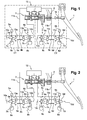
- the figure 1 represents a block diagram of a system according to the invention.
- a tandem master cylinder 3 connected to a reservoir 12 of hydraulic fluid makes it possible to feed two independent and identical braking circuits C 1 and C 2 .
- Each of the braking circuits is associated with two of the four wheels represented here by their brake disc 8a, 8b, 8c, 8d and allows to actuate two stirrups of the four respective stirrups 7a, 7b, 7c, 7d.
- Each stirrup is associated a normally open intake solenoid valve and a normally closed exhaust solenoid valve, in the example respectively four proportional solenoid valves 6a, 6b, 6c, 6d and four "all or nothing" type solenoid valves 13a, 13b, 13c, 13d.
- Each intake valve 6a, 6b, 6c, 6d is derived by an exhaust line having a valve 10a, 10b, 10c, 10d.
- Each braking circuit comprises a line 11a, 11b of return to the tank 12.
- a valve 9a, 9b, 9c, 9d is connected in series to the output of each exhaust solenoid valve 13a, 13b, 13c, 13d.
- At least one of the braking circuits C 1 and C 2 is furthermore equipped with a pressure sensor. In the example of the figure 1 each circuit has a clean pressure sensor 5a, 5b.
- the inlet solenoid valves 6a, 6b, 6c, 6d may be all or nothing type.
- An all-or-nothing solenoid valve is characterized by two states, a state of rest (which can be open or closed), and an activation state (which is the opposite state).
- a proportional solenoid valve has an infinity of states between a state of rest and a state of complete activation, which allows a progressive opening and closing. It can also be solenoid valve "flow”, that is to say, to control a flow, or solenoid valve "pressure”, that is to say, to control the pressure difference applied to this solenoid valve.
- the master cylinder 3 is actuated by a reversible active brake booster 2 connected to a brake pedal 1.
- the booster 2 is a reversible electromechanical actuator that amplifies the force received from the brake pedal 1, like a conventional brake booster, but can also reduce this effort (creating a resistant force) or even generate a single effort in the absence of action on the brake pedal from the driver.
- the force received from the pedal is measured by a force sensor 16.
- Reversible means that the actuator does not oppose the movement of the brake pedal when it is not powered.
- the figure 2 shows the movements of hydraulic fluid in the circuit during a conventional braking.
- the brake booster 2 amplifies this effort and transmits the resulting force to the master cylinder 3.
- the pressure generated by the master cylinder 3 is transmitted by the intake valves 6a, 6b, 6c, 6d normally open to stirrups 7a, 7b, 7c, 7d.
- the pressure received by the stirrups is converted into braking force.
- the figure 3 shows the state of the circuit during a release phase, that is to say when the driver releases the brake pedal after a braking phase.
- the fluid contained under pressure in the stirrups 7a, 7b, 7c, 7d flows towards the master cylinder 3 through the solenoid valves 6a, 6b, 6c, 6d which are passing through, as well as through the valves 10a, 10b , 10c, 10d.
- the figure 4 shows the circuit during a control phase of the system according to the invention, in which it is necessary to reduce the pressure in a single bracket, for example when a wheel locks during a braking phase.
- the normally open intake valve 6d of this caliper is activated.
- the caliper 7d is then isolated from the hydraulic circuit, its pressure can not increase.
- the normally closed exhaust solenoid valve 13d is activated which allows the pressurized fluid contained in the stirrup 7d to return to the reservoir 12 of the tandem master cylinder 3 through the valve 9d.
- the activation of the solenoid valves 6d and 8d may, depending on the case, not be simultaneous or total. Once the target pressure is reached, the exhaust solenoid valve 8d is deactivated. To increase the pressure of this stirrup 7d again, it suffices to deactivate the inlet solenoid valve 6d if the pressure of the master cylinder 3 measured by the sensor 5b is greater than that of the stirrup.
- the pressure of the stirrup 7d may decrease because the fluid contained under pressure in the caliper will be able to return to the tank 12 through the valve 10d.
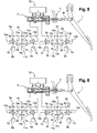
- the figure 5 shows the state of the circuit during a regulation phase requiring brake pressure without driver action, or with insufficient driver action. This corresponds in particular to the phases of actuation of the ESP.
- the brake booster 2 is activated and thus directly generates the required pressure. If, during this phase, the driver finally presses on the brake pedal or sufficiently increases the pressure it exerted, the effort that the driver exerts on the pedal is then added to the effort already provided by the brake booster 2 .
- the system comprises a displacement and / or effort sensor 16 associated with the brake pedal 1.
- a displacement and / or effort sensor 16 associated with the brake pedal 1.
- information on the position of the pedal, or the time derivative thereof enables functions to be performed. by varying the law of assistance which is provided by the brake booster 2.
- the emergency braking assistance function in which one detects a very sudden depression of the brake pedal and the the boosting force of the brake booster 2 is increased with respect to the nominal assistance effort.
- each of the braking circuits comprises a high-pressure accumulator 4a, 4b which makes it possible to damp the jolts in the circuit when the hydraulic fluid refluxes, for example during an antilocking control phase.
- These accumulators must be able to withstand the maximum permissible pressure in the calipers.
- each of the braking circuits comprises at the outlet of the exhaust solenoid valves 13a, 13b, 13c, 13d a low pressure hydraulic accumulator 14a, 14b replacing the return lines 11a, 11b and a valve 15a, 15b .
- the operation of the system during the braking and brake release phases is unchanged.
- the normally open inlet solenoid valve 6d of this caliper is activated. The caliper is isolated from the hydraulic circuit, its pressure can not increase.
- the normally closed exhaust solenoid valve 13d is activated which allows fluid contained under pressure in the caliper 7d to flow through the valve 9d to fill the low pressure accumulator 14b.
- This accumulator is dimensioned (stiffness and volume) so that it can collect all the fluid that is evacuated by the exhaust solenoid valves 13d while having a relatively low pressure increase 2 ion.
- the pressure of this accumulator may be lower than the master cylinder pressure 3 measured by the pressure sensor 5b because it is isolated from the circuit by the valve 15b.
- the activation of the solenoid valves 6d and 13d may not be simultaneous or total. Once the target pressure is reached, the exhaust solenoid valve 13d is deactivated.
- the pressure of the caliper 7d may decrease because the fluid contained in the caliper will be able to return to the tank by through the valve 10d.
- the brake pedal is connected to a stroke and effort simulator as it has been developed for the braking systems of hybrid vehicles for example.
- the use of such a simulator would improve the feeling of the driver's pedal during the pressure regulation phases via the brake booster.
- the return lines 11a and 11b may be common to the two braking circuits C 1 and C 2 .
Abstract
Description
La présente invention est relative à un système de contrôle de stabilité et de trajectoire pour un véhicule automobile.The present invention relates to a stability and trajectory control system for a motor vehicle.
Un système de contrôle de stabilité et de trajectoire, connu notamment sous le nom d'E.S.P., a pour objectif d'augmenter ou de générer le couple de freinage appliqué à une roue si une unité de contrôle électronique en charge de la commande du système détecte qu'une consigne conducteur est inexistante, insuffisante ou au contraire trop importante, au regard d'une situation de stabilité du véhicule, cette situation étant déterminée à partir de mesures effectuées par différents capteurs installés dans le véhicule.A stability and trajectory control system, known especially under the name of ESP, aims to increase or generate the braking torque applied to a wheel if an electronic control unit in charge of the system control detects that a driving instruction is non-existent, insufficient or on the contrary too important, in view of a situation of stability of the vehicle, this situation being determined from measurements made by various sensors installed in the vehicle.
L'action principale d'un système de contrôle de stabilité consiste donc à augmenter ou générer un couple de freinage si la consigne du conducteur appliquée à la pédale de frein est insuffisante ou inexistanteThe main action of a stability control system is therefore to increase or generate a braking torque if the driver's instruction applied to the brake pedal is insufficient or non-existent.
Parallèlement, il est également connu des systèmes d'anti-blocage des roues lors d'un freinage (couramment appelé A.B.S). Le système A.B.S. permet de conserver la dirigeabilité du véhicule en situation de freinage d'urgence ou sur revêtement à faible adhérence. A cet effet, un capteur de vitesse est disposé au niveau de chaque roue. A partir de ces mesures de vitesse, un calculateur évalue le glissement relatif de chaque roue et régule la puissance du freinage sur chacune des roues de façon à empêcher le blocage de l'une d'entre elles.At the same time, anti-lock braking systems (commonly called A.B.S) are also known. A.B.S. maintains the vehicle's ability to steer in emergency braking situations or on low-friction surfaces. For this purpose, a speed sensor is disposed at each wheel. From these speed measurements, a computer evaluates the relative slip of each wheel and regulates the braking power on each of the wheels so as to prevent the blocking of one of them.
Les moyens de calcul et de régulation du système de contrôle de stabilité et de trajectoire sont en outre couramment employés afin de réaliser un système d'anti-patinage (couramment appelé A.S.R.).The calculation and regulation means of the stability and trajectory control system are also commonly used in order to achieve an anti-skid system (commonly called A.S.R.).
Les systèmes de contrôle de stabilité et de motricité existants sont des systèmes hydrauliques se greffant sur le (les) circuit(s) de freinage du véhicule, et, le cas échéant, constituent un système unique assurant les fonctions de contrôle de stabilité, d'antiblocage et d'anti-patinage.The existing stability and traction control systems are hydraulic systems grafting onto the vehicle braking circuit (s) and, where appropriate, constitute a single system providing the stability control functions of the vehicle. anti-lock and anti-slip.
De tels systèmes équipent aujourd'hui couramment les véhicules de moyenne et haute gammes, mais, en raison d'un surcoût important, sont encore peu installés sur les véhicules d'entrée de gamme, en dépit de leur apport incontestable en terme de sécurité.Such systems are nowadays commonly used medium and high range vehicles, but, because of significant additional cost, are still installed on the entry level vehicles, despite their undeniable contribution in terms of safety.
Atténuer l'impact économique de l'intégration d'un système de contrôle de stabilité dans un véhicule automobile constitue ainsi un enjeu primordial pour les constructeurs automobiles.Mitigating the economic impact of integrating a stability control system into a motor vehicle is therefore a major issue for car manufacturers.
Le surcoût important de ces systèmes est, pour la plus grande part, dû à la partie opérative, comprenant des composants hydrauliques dont l'intégration s'avère coûteuse et complexe, comme expliqué ci-après.The major additional cost of these systems is, for the most part, due to the operative part, comprising hydraulic components whose integration is expensive and complex, as explained below.
Le système de freinage d'un véhicule dépourvu de système de régulation comporte, de manière connue, un circuit hydraulique permettant d'actionner des étiers de frein équipant chacun des disques de frein dont est pourvue chacune des roues (éventuellement remplacés par un ensemble tambour/mâchoire). Le circuit hydraulique est mis en pression lorsque le conducteur exerce un effort sur la pédale de frein au moyen d'un maître-cylindre alimenté par un réservoir de fluide. Les exigences règlementaires de sécurité imposent de prévoir deux circuits de freinage indépendants, chaque circuit assurant le freinage de deux roues, par exemple, une roue avant et une roue arrière de côté opposé. On utilise à cet effet un maître-cylindre dit « tandem », comportant deux chambres de compression alimentant chacune un des deux circuits. Entre le maître-cylindre et la pédale est interposé un dispositif d'amplification, le servofrein (aussi connu sous le nom de « booster »).The braking system of a vehicle without a regulation system includes, in known manner, a hydraulic circuit for actuating brake shoes fitted to each of the brake disks which each wheel is provided with (possibly replaced by a drum unit / jaw). The hydraulic circuit is pressurized when the driver exerts a force on the brake pedal by means of a master cylinder fed by a fluid reservoir. The regulatory safety requirements make it necessary to provide two independent braking circuits, each circuit ensuring the braking of two wheels, for example a front wheel and a rear wheel on the opposite side. For this purpose, a so-called master cylinder is used. "Tandem", comprising two compression chambers each feeding one of the two circuits. Between the master cylinder and the pedal is interposed an amplification device, the brake booster (also known as "booster").
L'implantation d'un système de contrôle de stabilité et de trajectoire sur un tel système de freinage impose généralement la présence sur chacun des deux circuits de freinage d'une pompe, d'une électrovanne, ouverte en position de repos, permettant d'isoler le maître-cylindre tandem du circuit hydraulique, d'une électrovanne d'aspiration, fermée en position de repos, installée entre le maître-cylindre tandem et la pompe (côté admission), d'électrovannes d'admission et d'échappement pour chacun des étriers, ainsi que d'un accumulateur basse pression.The implementation of a stability and trajectory control system on such a braking system generally imposes the presence on each of the two braking circuits of a pump, a solenoid valve, open in the rest position, allowing isolating the tandem master cylinder from the hydraulic circuit, a suction solenoid valve, closed in the rest position, installed between the tandem master cylinder and the pump (intake side), intake and exhaust solenoid valves for each of the stirrups, as well as a low pressure accumulator.
L'un des éléments les plus coûteux de cet ensemble est la pompe hydraulique et il est connu du document
La présente invention a pour objet de pallier les inconvénients de l'art antérieur en proposant un système et un procédé de contrôle de la stabilité, de la trajectoire et de l'adhérence d'un véhicule fonctionnant sans pompe hydraulique, quelle que soit l'action de régulation envisagée : augmentation, diminution ou génération d'une pression de freinage.The object of the present invention is to overcome the drawbacks of the prior art by proposing a system and a method for controlling the stability, the trajectory and the adhesion of a vehicle operating without a hydraulic pump, whatever the envisaged control action: increase, decrease or generation of a brake pressure.
De manière plus précise, l'invention concerne un système de contrôle de stabilité et de trajectoire d'un véhicule automobile, apte à moduler individuellement la pression hydraulique alimentant chacun de quatre éléments de frein d'un véhicule automobile et comprenant :
- un maître cylindre tandem alimentant individuellement deux circuits de freinage, chaque circuit de freinage alimentant deux éléments de frein ;
- un servofrein destiné à agir sur le maître cylindre, apte à moduler un effort reçu de la pédale de commande de frein et à générer un effort en l'absence d'action sur la pédale de commande ;
- une électrovanne d'admission d'admission normalement ouverte associée à chacun des éléments de frein ;
- une électrovanne d'échappement normalement fermée associée à chacun des éléments de frein ;
- a tandem master cylinder individually supplying two braking circuits, each braking circuit feeding two brake elements;
- a brake booster intended to act on the master cylinder, able to modulate a force received from the brake pedal and to generate a force in the absence of action on the pedal;
- a normally open intake admission solenoid valve associated with each of the brake members;
- a normally closed exhaust solenoid valve associated with each of the brake members;
le système étant apte à augmenter ou diminuer la pression individuellement dans un ou plusieurs éléments de frein par actionnement des électrovanne(s) d'admission et d'échappement associée(s) à (aux) l'élément de frein concerné(s) conjointement à l'utilisation du servofrein.the system being adapted to increase or decrease the pressure individually in one or more brake elements by actuating the inlet and exhaust solenoid valves associated with the brake element (s) concerned the use of the brake booster.
Dans une réalisation préférentielle, un élément de frein est la combinaison d'un étrier de frein et d'un disque associés à une roueIn a preferred embodiment, a brake element is the combination of a brake caliper and a disc associated with a wheel
Dans une réalisation, dans laquelle le système permet de réaliser une fonction d'antiblocage des roues, le système est apte à détecter le risque de blocage d'une ou plusieurs roues lors d'un freinage, à isoler la(les) roue(s) bloquée en activant l'électrovanne d'admission associée puis à diminuer l'effort de freinage en activant l'électrovanne d'échappement associée pour diminuer la pression dans l'élément de frein.In one embodiment, in which the system makes it possible to perform an anti-lock function of the wheels, the system is able to detect the risk of locking one or more wheels during braking, to isolate the wheel (s). ) blocked by activating the associated intake solenoid valve and then to reduce the braking force by activating the associated exhaust solenoid valve to reduce the pressure in the brake element.
Dans une réalisation, dans laquelle le système permet de réaliser une fonction de contrôle de stabilité et de trajectoire, le système est apte à générer un effort de freinage individuellement dans une ou plusieurs roue(s) en isolant les autres roues en activant les électrovannes d'admission associées (6b, 6c, 6d) puis à activer le servofrein pour générer un effort de freinage et ralentir la rotation de la (les) roue(s).In one embodiment, in which the system makes it possible to perform a stability and trajectory control function, the system is able to generate a braking force individually in one or more wheel (s) by isolating the other wheels by activating the solenoid valves. associated admission (6b, 6c, 6d) then to activate the brake booster to generate a braking force and slow down the rotation of the wheel (s).
Selon d'autres réalisations encore, le système comprend une ou plusieurs des caractéristiques suivantes, seule ou en combinaison :
- chaque circuit de freinage du système comporte une ligne de retour reliant la sortie des électrovannes d'échappement du circuit concerné au réservoir du maître cylindre,
- chaque circuit de freinage du système comporte un accumulateur hydraulique basse pression disposé à la sortie des électrovannes d'échappement du circuit concerné,
- un clapet est disposé en série à la sortie de chaque accumulateur,
- un clapet est associé en parallèle à chacun des électrovannes d'amission,
- un clapet est monté en série à la sortie de chaque électrovanne d'échappement ,
- le servofrein est un actionneur électromécanique réversible,
- le servofrein est un actionneur électromécanique irréversible, le servofrein étant lié à la pédale par un mécanisme d'accouplement.,
- au moins une des électrovannes d'admission est une électrovanne de type proportionnel.
- au moins une des électrovannes d'échappement est une électrovanne de type « tout ou rien »,
- au moins l'un des deux circuits de freinage comporte un capteur de pression hydraulique,
- le système comprend un capteur d'effort associé à la pédale de commande de frein,
- le système comprend un capteur de position associé à la pédale de commande de frein,
- chaque circuit de freinage comprend un accumulateur haute pression,
- le système comprend un simulateur de course et d'effort relié à la pédale de frein.
- each braking circuit of the system comprises a return line connecting the output of the exhaust solenoid valves of the circuit concerned to the reservoir of the master cylinder,
- each braking circuit of the system comprises a low pressure hydraulic accumulator disposed at the outlet of the exhaust solenoid valves of the circuit concerned,
- a valve is arranged in series at the outlet of each accumulator,
- a valve is associated in parallel with each of the solenoid valves,
- a valve is mounted in series at the outlet of each exhaust solenoid valve,
- the brake booster is a reversible electromechanical actuator,
- the brake booster is an irreversible electromechanical actuator, the brake booster being connected to the pedal by a coupling mechanism.
- at least one of the intake solenoid valves is a proportional type solenoid valve.
- at least one of the exhaust solenoid valves is an "all or nothing" solenoid valve,
- at least one of the two braking circuits comprises a hydraulic pressure sensor,
- the system includes a force sensor associated with the brake control pedal,
- the system includes a position sensor associated with the brake pedal,
- each braking circuit comprises a high pressure accumulator,
- the system includes a simulator of stroke and effort connected to the brake pedal.
L'invention concerne également un procédé de contrôle de stabilité et de trajectoire de véhicule, et/ou d'antiblocage de roues, destiné à être mis en oeuvre dans un véhicule automobile muni d'un système conforme à l'invention, ce procédé comprenant les étapes suivantes, qui consistent à :
- surveiller les vitesses de rotation des roues;
- détecter un risque de blocage d'une roue ;
- activer l'électrovanne d'admission de la roue bloquée;
- activer l'électrovanne d'échappement de la roue bloquée
- maintenir ou moduler l'effort d'assistance fourni par le servofrein afin de maintenir la pression dans les étriers des roues non bloquées tandis que,
- lorsque la roue bloquée se débloque; désactiver les électrovannes d'admission et d'échappement associées.
- monitor the rotational speeds of the wheels;
- detect a risk of locking a wheel;
- activate the inlet solenoid valve of the locked wheel;
- activate the exhaust solenoid valve of the locked wheel
- maintain or modulate the assistance effort provided by the brake booster to maintain pressure in the unblocked wheel calipers while,
- when the locked wheel is unlocked; deactivate the associated intake and exhaust solenoid valves.
Dans une réalisation, le procédé comprend, en outre, les étapes suivantes, consistant à :
- lorsqu'un écart survient entre les trajectoires réelle et souhaitée, déterminer une roue devant être freinée pour diminuer cet écart, ainsi que l'effort de freinage à appliquer à cette roue;
- activer les électrovannes d'admission des autres roues.
- activer le servofrein pour générer l'effort de freinage nécessaire sur la roue;
- lorsque l'écart entre les trajectoires réelle et souhaitée est corrigé, désactiver le servofrein;
- désactiver les électrovannes d'admission des roues non bloquées.
- when a difference occurs between the actual and desired trajectories, determining a wheel to be braked to reduce this difference, as well as the braking force to be applied to this wheel;
- activate the intake solenoid valves of the other wheels.
- activate the brake booster to generate the necessary braking force on the wheel;
- when the difference between the actual and desired paths is corrected, deactivate the brake booster;
- deactivate the solenoid valves for unblocked wheels.
L'invention concerne également un véhicule automobile pourvu d'un système conforme à l'invention, ou mettant en oeuvre un procédé conforme à l'invention.The invention also relates to a motor vehicle provided with a system according to the invention, or implementing a method according to the invention.
Un exemple de réalisation de l'invention est décrit ci-après, de manière non limitative, en relation avec les figures annexées, parmi lesquelles :
- la
figure 1 montre un schéma d'un système selon l'invention; - les
figures 2 et 3 montrent l'état du système de lafigure 1 , respectivement lors de phases classiques de freinage et de défreinage; - la
figure 4 montre l'état du système de lafigure 1 lors d'une phase de freinage nécessitant la mise en oeuvre de la fonction d'antiblocage ; - les
figures 5 et 6 montrent une variante du système représenté à lafigure 1 .
- the
figure 1 shows a diagram of a system according to the invention; - the
figures 2 and3 show the state of the system thefigure 1 respectively during conventional braking and brake release phases; - the
figure 4 shows the state of the system of thefigure 1 during a braking phase requiring the implementation of the anti-lock function; - the
Figures 5 and 6 show a variant of the system shown infigure 1 .
Les éléments identiques d'une variante à l'autre conservent les mêmes références sur les différentes figures.The identical elements from one variant to another retain the same references in the different figures.
La
Selon les cas, les électrovannes d'admission 6a, 6b, 6c, 6d peuvent être de type tout ou rien. Une électrovanne tout ou rien est caractérisée par deux états, un état de repos (qui peut être ouvert ou fermé), et un état d'activation (qui est l'état contraire). Une électrovanne proportionnelle comporte une infinité d'états entre un état de repos et un état d'activation complète, ce qui permet de procéder à une ouverture et une fermeture progressives. Il peut également s'agir d'électrovanne « débit », c'est-à-dire permettant de contrôler un débit, ou d'électrovanne « pression », c'est-à-dire permettant de contrôler la différence de pressions appliquée à cette électrovanne.Depending on the case, the
Le maître cylindre 3 est actionné par un servofrein actif réversible 2 relié à une pédale de frein 1. Le servofrein 2 est un actionneur électromécanique réversible qui permet d'amplifier l'effort reçu de la pédale de frein 1, comme un servofrein classique, mais peut également amoindrir cet effort (création d'un effort résistant) ou encore générer seul un effort en l'absence d'action sur la pédale de frein de la part du conducteur. L'effort reçu de la pédale est mesuré grâce à un capteur d'effort 16. Par réversible, on entend que l'actionneur ne s'oppose pas au mouvement de la pédale de frein lorsque celui-ci n'est pas alimenté. En variante, on peut envisager l'utilisation d'un actionneur irréversible en combinaison avec un système d'accouplement débrayable, afin que, pour des raisons de sécurité il soit toujours possible de freiner, notamment lorsque l'actionneur tombe en panne.The
On décrit ci-après le fonctionnement du système selon l'invention à travers les phases de freinage et défreinage classiques, ainsi qu'à travers des phases de régulation du système de contrôle de stabilité et de trajectoire.The operation of the system according to the invention is described below through the conventional braking and brake release phases, as well as through the regulation phases of the stability and trajectory control system.
Ainsi, la
La
La
Dans le cas où le conducteur relâche la pédale de frein et que l'électrovanne d'admission 6d est activée (i.e. fermée), la pression de l'étrier 7d peut diminuer car le fluide contenu sous pression dans l'étrier aura la possibilité de retourner au réservoir 12 par l'intermédiaire du clapet 10d.In the case where the driver releases the brake pedal and the
La
Dans une variante, le système comprend un capteur de déplacement et/ou d'effort 16 associé à la pédale de frein 1. Ainsi l'information sur la position de la pédale, ou la dérivée temporelle de celle-ci permet de réaliser des fonctions supplémentaires en faisant varier la loi d'assistance qui est assurée par le servofrein 2. Par exemple, on peut réaliser la fonction d'aide au freinage d'urgence, dans laquelle on détecte un enfoncement très brusque de la pédale de frein et l'on augmente l'effort d'assistance du servofrein 2 par rapport à l'effort d'assistance nominal. En l'absence de capteur de déplacement, on peut cependant utiliser comme information le gradient de la force appliquée par le conducteur sur la pédale de frein 1 pour réaliser la fonction d'aide au freinage d'urgence.In one variant, the system comprises a displacement and / or
Dans une variante, chacun des circuits de freinage comporte un accumulateur haute pression 4a, 4b qui permet d'amortir les à coups dans le circuit lorsque le fluide hydraulique reflue, par exemple lors d'une phase de régulation antiblocage. Ces accumulateurs doivent pouvoir supporter la pression maximale admissible dans les étriers.In a variant, each of the braking circuits comprises a high-
Dans une variante représentée sur les
Dans le cas où le conducteur relâche la pédale de frein et que l'électrovanne d'admission est activée (fermée), la pression de l'étrier 7d peut diminuer car le fluide contenu dans l'étrier aura la possibilité de retourner au réservoir par l'intermédiaire du clapet 10d.In the case where the driver releases the brake pedal and the intake solenoid valve is activated (closed), the pressure of the
Dans une variante, la pédale de frein est reliée à un simulateur de course et d'effort comme il en a été développé pour les systèmes de freinage des véhicules hybrides par exemple. L'utilisation d'un tel simulateur permettrait d'améliorer le ressenti à la pédale du conducteur lors des phases de régulation de pression par l'intermédiaire du servofrein.In a variant, the brake pedal is connected to a stroke and effort simulator as it has been developed for the braking systems of hybrid vehicles for example. The use of such a simulator would improve the feeling of the driver's pedal during the pressure regulation phases via the brake booster.
Dans une variante, les lignes de retour 11a et 11b peuvent être communes au deux circuits de freinage C1 et C2.In a variant, the
Claims (21)
le système étant apte à augmenter ou diminuer la pression individuellement dans un ou plusieurs éléments de frein par actionnement des électrovanne(s) d'admission (6a, 6b, 6c, 6d) et d'échappement (13a, 13b, 13c, 13d) associée(s) à (aux) l'élément de frein concerné(s) conjointement à l'utilisation du servofrein (2).
the system being adapted to increase or decrease the pressure individually in one or more brake elements by actuating the solenoid valve (s) (6a, 6b, 6c, 6d) and exhaust (13a, 13b, 13c, 13d) associated with the brake element (s) concerned in conjunction with the use of the brake booster (2).
Applications Claiming Priority (1)
| Application Number | Priority Date | Filing Date | Title |
|---|---|---|---|
| FR0851827A FR2928889B1 (en) | 2008-03-20 | 2008-03-20 | STABILITY AND TRACK CONTROL SYSTEM OF A MOTOR VEHICLE USING AN ACTIVE SERVOFREIN |
Publications (1)
| Publication Number | Publication Date |
|---|---|
| EP2103493A1 true EP2103493A1 (en) | 2009-09-23 |
Family
ID=39830369
Family Applications (1)
| Application Number | Title | Priority Date | Filing Date |
|---|---|---|---|
| EP09155658A Withdrawn EP2103493A1 (en) | 2008-03-20 | 2009-03-19 | System for controlling the stability and the trajectory of an automotive vehicle using an active brake booster |
Country Status (2)
| Country | Link |
|---|---|
| EP (1) | EP2103493A1 (en) |
| FR (1) | FR2928889B1 (en) |
Cited By (6)
| Publication number | Priority date | Publication date | Assignee | Title |
|---|---|---|---|---|
| WO2011098176A1 (en) * | 2010-02-15 | 2011-08-18 | Robert Bosch Gmbh | Method for operating a hydraulic brake system of a vehicle and control device for a hydraulic brake system of a vehicle |
| WO2011116998A1 (en) * | 2010-03-25 | 2011-09-29 | Robert Bosch Gmbh | Device and method for controlling a brake system |
| WO2012152352A1 (en) * | 2011-05-10 | 2012-11-15 | Lucas Automotive Gmbh | Hydraulic vehicle braking system with electromechanical actuator, and method for operating such a hydraulic vehicle braking system |
| WO2013131887A1 (en) * | 2012-03-06 | 2013-09-12 | Continental Teves Ag & Co. Ohg | Method for operating a brake system for motor vehicles, and brake system |
| CN103381801A (en) * | 2012-05-03 | 2013-11-06 | 现代摩比斯株式会社 | Vehicle brake apparatus |
| CN113654897A (en) * | 2021-06-28 | 2021-11-16 | 杭州长川科技股份有限公司 | Pressure regulating system, control method thereof, pressure regulating device and electronic element crimping system |
Citations (10)
| Publication number | Priority date | Publication date | Assignee | Title |
|---|---|---|---|---|
| EP0240688A1 (en) * | 1986-04-11 | 1987-10-14 | Robert Bosch Gmbh | Anti-lock brake system |
| EP0456597A1 (en) * | 1990-05-07 | 1991-11-13 | Richard A. Cardenas | Adjustable pressure control device for hydraulic brake systems |
| DE4121470A1 (en) * | 1990-07-03 | 1992-01-09 | Nippon Denso Co | BRAKE PRESSURE CONTROL DEVICE FOR MOTOR VEHICLES |
| US5390989A (en) * | 1993-03-24 | 1995-02-21 | Kim; Joowon | Adjustable pressure variable response fluid brake system accumulator |
| WO1995011824A1 (en) * | 1993-10-26 | 1995-05-04 | Robert Bosch Gmbh | Hydraulic braking system |
| DE19652889A1 (en) * | 1995-12-20 | 1997-06-26 | Denso Corp | ABS braking control arrangement for motor vehicle |
| WO1997035753A1 (en) * | 1996-03-23 | 1997-10-02 | Itt Manufacturing Enterprises, Inc. | Pumpless braking pressure regulating system for motor vehicles |
| WO1997048584A1 (en) * | 1996-06-19 | 1997-12-24 | Itt Manufacturing Enterprises, Inc. | Hydraulic motor vehicle braking system with electronic anti-lock control and circuit for such a braking system |
| WO2004005095A1 (en) * | 2002-07-09 | 2004-01-15 | Continental Teves Ag & Co. Ohg | Brake by-wire actuator |
| DE10338046A1 (en) | 2003-08-19 | 2005-03-10 | Volkswagen Ag | Motor vehicle braking system has an active brake amplifier and is configured so that electronic stability functionality or other such regimes are integrated solely by controlling the brake amplifier and the wheel brake valves |
-
2008
- 2008-03-20 FR FR0851827A patent/FR2928889B1/en active Active
-
2009
- 2009-03-19 EP EP09155658A patent/EP2103493A1/en not_active Withdrawn
Patent Citations (10)
| Publication number | Priority date | Publication date | Assignee | Title |
|---|---|---|---|---|
| EP0240688A1 (en) * | 1986-04-11 | 1987-10-14 | Robert Bosch Gmbh | Anti-lock brake system |
| EP0456597A1 (en) * | 1990-05-07 | 1991-11-13 | Richard A. Cardenas | Adjustable pressure control device for hydraulic brake systems |
| DE4121470A1 (en) * | 1990-07-03 | 1992-01-09 | Nippon Denso Co | BRAKE PRESSURE CONTROL DEVICE FOR MOTOR VEHICLES |
| US5390989A (en) * | 1993-03-24 | 1995-02-21 | Kim; Joowon | Adjustable pressure variable response fluid brake system accumulator |
| WO1995011824A1 (en) * | 1993-10-26 | 1995-05-04 | Robert Bosch Gmbh | Hydraulic braking system |
| DE19652889A1 (en) * | 1995-12-20 | 1997-06-26 | Denso Corp | ABS braking control arrangement for motor vehicle |
| WO1997035753A1 (en) * | 1996-03-23 | 1997-10-02 | Itt Manufacturing Enterprises, Inc. | Pumpless braking pressure regulating system for motor vehicles |
| WO1997048584A1 (en) * | 1996-06-19 | 1997-12-24 | Itt Manufacturing Enterprises, Inc. | Hydraulic motor vehicle braking system with electronic anti-lock control and circuit for such a braking system |
| WO2004005095A1 (en) * | 2002-07-09 | 2004-01-15 | Continental Teves Ag & Co. Ohg | Brake by-wire actuator |
| DE10338046A1 (en) | 2003-08-19 | 2005-03-10 | Volkswagen Ag | Motor vehicle braking system has an active brake amplifier and is configured so that electronic stability functionality or other such regimes are integrated solely by controlling the brake amplifier and the wheel brake valves |
Cited By (13)
| Publication number | Priority date | Publication date | Assignee | Title |
|---|---|---|---|---|
| CN103118914B (en) * | 2010-02-15 | 2015-07-29 | 罗伯特·博世有限公司 | Method for the hydraulic brake system of operational vehicle and the control setup for this system |
| CN103118914A (en) * | 2010-02-15 | 2013-05-22 | 罗伯特·博世有限公司 | Method for operating a hydraulic brake system of a vehicle and control device for a hydraulic brake system of a vehicle |
| WO2011098176A1 (en) * | 2010-02-15 | 2011-08-18 | Robert Bosch Gmbh | Method for operating a hydraulic brake system of a vehicle and control device for a hydraulic brake system of a vehicle |
| WO2011116998A1 (en) * | 2010-03-25 | 2011-09-29 | Robert Bosch Gmbh | Device and method for controlling a brake system |
| WO2012152352A1 (en) * | 2011-05-10 | 2012-11-15 | Lucas Automotive Gmbh | Hydraulic vehicle braking system with electromechanical actuator, and method for operating such a hydraulic vehicle braking system |
| US9227611B2 (en) | 2011-05-10 | 2016-01-05 | Lucas Automotive Gmbh | Hydraulic vehicle braking system with electromechanical actuator, and method for operating such a hydraulic vehicle braking system |
| US10259440B2 (en) | 2011-05-10 | 2019-04-16 | Lucas Automotive Gmbh | Hydraulic vehicle braking system with electromechanical actuator, and method for operating such a hydraulic vehicle braking system |
| WO2013131887A1 (en) * | 2012-03-06 | 2013-09-12 | Continental Teves Ag & Co. Ohg | Method for operating a brake system for motor vehicles, and brake system |
| US9566960B2 (en) | 2012-03-06 | 2017-02-14 | Continental Teves Ag & Co. Ohg | Method for operating a brake system for motor vehicles, and brake system |
| CN103381801A (en) * | 2012-05-03 | 2013-11-06 | 现代摩比斯株式会社 | Vehicle brake apparatus |
| CN103381801B (en) * | 2012-05-03 | 2016-03-30 | 现代摩比斯株式会社 | Braking device for vehicle |
| CN113654897A (en) * | 2021-06-28 | 2021-11-16 | 杭州长川科技股份有限公司 | Pressure regulating system, control method thereof, pressure regulating device and electronic element crimping system |
| CN113654897B (en) * | 2021-06-28 | 2024-03-26 | 杭州长川科技股份有限公司 | Pressure regulating system, control method thereof, pressure regulating device and electronic element crimping system |
Also Published As
| Publication number | Publication date |
|---|---|
| FR2928889B1 (en) | 2015-03-06 |
| FR2928889A1 (en) | 2009-09-25 |
Similar Documents
| Publication | Publication Date | Title |
|---|---|---|
| FR2711342A1 (en) | Brake pressure control device for a road vehicle. | |
| EP2103493A1 (en) | System for controlling the stability and the trajectory of an automotive vehicle using an active brake booster | |
| FR2860849A1 (en) | Wheel disc brake for e.g. motorbike, has electromechanical and hydraulic actuators to press brake lining against brake disc, and auto-amplifier converting friction force exerted on lining by actuators to push pressing lining against disc | |
| FR2813248A1 (en) | METHOD AND DEVICE FOR CONTROLLING WHEEL BRAKES OF A VEHICLE | |
| FR2556672A1 (en) | HYDRAULIC BRAKE SYSTEM | |
| JP6516266B2 (en) | Brake control method and device | |
| FR2658464A1 (en) | VEHICLE BRAKE SYSTEM WITH ANTI-LOCK DEVICE AND RETURN PUMP, AND METHOD FOR ITS IMPLEMENTATION | |
| EP2103494A1 (en) | System for controlling the stability and the trajectory of an automotive vehicle using an active brake booster | |
| EP2098425B1 (en) | Braking systems allowing the execution of a method for controlling the stability and trajectory | |
| FR3065932A1 (en) | BRAKING SYSTEM WITH INDEPENDENT ACTUATION OF AT LEAST TWO WHEELS OF AN AXLE OF A MOTOR VEHICLE | |
| FR2964073A1 (en) | Hydraulic braking controller for controlling wheel brake of motor vehicle, has distributor alternatively connecting outlet of master-cylinder to small chamber or large chamber when depression amplifier is in faulty or operating condition | |
| EP2127977A1 (en) | System for controlling the stability and the trajectory of an automobile using an active brake servo unit | |
| FR2931767A1 (en) | BRAKING SYSTEM FOR CONTROLLING THE STABILITY AND TRACKING OF A MOTOR VEHICLE AND METHODS OF USING SUCH A SYSTEM | |
| FR2931768A1 (en) | BRAKING SYSTEM FOR CONTROLLING THE STABILITY AND TRACKING OF A MOTOR VEHICLE AND METHODS OF USING SUCH A SYSTEM | |
| FR2915802A1 (en) | Wheel's adhesion determining method for motor vehicle, involves applying braking action on one of wheels of vehicle, measuring parameter varying according to brake, and determining value of adhesion coefficient from measured parameter | |
| EP2098428B1 (en) | Braking regulation system to control the stability and trajectory of an automotive vehicle | |
| FR2931772A1 (en) | Stability and trajectory controlling system for hybrid vehicle, has electrovalves associated with non-motorized and motorized calipers, where system decreases pressure in motorized calipers by actuating electrovalves and concerned calipers | |
| FR2931773A1 (en) | Stability and trajectory controlling system for hybrid vehicle, has electrovalves associated to motorized and non-motorized calipers, where system decreases pressure in motorized calipers by actuating electrovalves and concerned calipers | |
| FR2931771A1 (en) | Stability and trajectory controlling system for hybrid vehicle, has electrovalves associated to motorized and non-motorized calipers, where system decreases pressure in motorized calipers by actuating electrovalves and motorized calipers | |
| EP2098427B1 (en) | Braking regulation system to control the stability and trajectory of an automotive vehicle | |
| EP3478547B1 (en) | Motor vehicle parking brake control device | |
| FR2843926A1 (en) | ANTI-SKATING AND ANTI-LOCKING DEVICE OF THE WHEELS OF A VEHICLE USING THE BRAKING CIRCUIT | |
| EP3222478B1 (en) | Redundant braking system | |
| FR3069219B1 (en) | BRAKE SYSTEM FOR VEHICLE AND CORRESPONDING BRAKE CONTROL METHOD | |
| FR2928326A1 (en) | Braking system e.g. electronic stability control braking system, for motor vehicle, has traction system for transmitting hydraulic energy from pump to accumulator in order to store energy in accumulator |
Legal Events
| Date | Code | Title | Description |
|---|---|---|---|
| PUAI | Public reference made under article 153(3) epc to a published international application that has entered the european phase |
Free format text: ORIGINAL CODE: 0009012 |
|
| AK | Designated contracting states |
Kind code of ref document: A1 Designated state(s): AT BE BG CH CY CZ DE DK EE ES FI FR GB GR HR HU IE IS IT LI LT LU LV MC MK MT NL NO PL PT RO SE SI SK TR |
|
| AX | Request for extension of the european patent |
Extension state: AL BA RS |
|
| 17P | Request for examination filed |
Effective date: 20100319 |
|
| 17Q | First examination report despatched |
Effective date: 20100412 |
|
| AKX | Designation fees paid |
Designated state(s): AT BE BG CH CY CZ DE DK EE ES FI FR GB GR HR HU IE IS IT LI LT LU LV MC MK MT NL NO PL PT RO SE SI SK TR |
|
| STAA | Information on the status of an ep patent application or granted ep patent |
Free format text: STATUS: THE APPLICATION IS DEEMED TO BE WITHDRAWN |
|
| 18D | Application deemed to be withdrawn |
Effective date: 20110628 |