EP2103357A1 - Curtain coating apparatus and curtain coating method - Google Patents
Curtain coating apparatus and curtain coating method Download PDFInfo
- Publication number
- EP2103357A1 EP2103357A1 EP09155244A EP09155244A EP2103357A1 EP 2103357 A1 EP2103357 A1 EP 2103357A1 EP 09155244 A EP09155244 A EP 09155244A EP 09155244 A EP09155244 A EP 09155244A EP 2103357 A1 EP2103357 A1 EP 2103357A1
- Authority
- EP
- European Patent Office
- Prior art keywords
- curtain
- support member
- edge guide
- coating liquid
- windshield plate
- Prior art date
- Legal status (The legal status is an assumption and is not a legal conclusion. Google has not performed a legal analysis and makes no representation as to the accuracy of the status listed.)
- Granted
Links
- 238000007766 curtain coating Methods 0.000 title claims abstract description 94
- 238000000034 method Methods 0.000 title claims description 48
- 238000000576 coating method Methods 0.000 claims abstract description 135
- 239000011248 coating agent Substances 0.000 claims abstract description 134
- 239000007788 liquid Substances 0.000 claims abstract description 118
- 239000010408 film Substances 0.000 description 76
- 238000011156 evaluation Methods 0.000 description 18
- 210000000078 claw Anatomy 0.000 description 17
- 238000000151 deposition Methods 0.000 description 16
- 230000008021 deposition Effects 0.000 description 14
- 239000003570 air Substances 0.000 description 12
- 238000004519 manufacturing process Methods 0.000 description 12
- 230000004048 modification Effects 0.000 description 10
- 238000012986 modification Methods 0.000 description 10
- 239000012080 ambient air Substances 0.000 description 6
- 230000000052 comparative effect Effects 0.000 description 6
- 239000000047 product Substances 0.000 description 4
- 230000000903 blocking effect Effects 0.000 description 3
- 230000002950 deficient Effects 0.000 description 3
- 239000000463 material Substances 0.000 description 3
- 238000011144 upstream manufacturing Methods 0.000 description 3
- XEEYBQQBJWHFJM-UHFFFAOYSA-N Iron Chemical compound [Fe] XEEYBQQBJWHFJM-UHFFFAOYSA-N 0.000 description 2
- 238000001035 drying Methods 0.000 description 2
- 229910052751 metal Inorganic materials 0.000 description 2
- 239000002184 metal Substances 0.000 description 2
- 239000000203 mixture Substances 0.000 description 2
- 230000002829 reductive effect Effects 0.000 description 2
- 239000007787 solid Substances 0.000 description 2
- XLYOFNOQVPJJNP-UHFFFAOYSA-N water Substances O XLYOFNOQVPJJNP-UHFFFAOYSA-N 0.000 description 2
- 238000004804 winding Methods 0.000 description 2
- 229920002799 BoPET Polymers 0.000 description 1
- 239000004372 Polyvinyl alcohol Substances 0.000 description 1
- 241000220317 Rosa Species 0.000 description 1
- 229920006362 Teflon® Polymers 0.000 description 1
- 229910052782 aluminium Inorganic materials 0.000 description 1
- XAGFODPZIPBFFR-UHFFFAOYSA-N aluminium Chemical compound [Al] XAGFODPZIPBFFR-UHFFFAOYSA-N 0.000 description 1
- 230000008859 change Effects 0.000 description 1
- 238000010924 continuous production Methods 0.000 description 1
- 238000010586 diagram Methods 0.000 description 1
- 239000012467 final product Substances 0.000 description 1
- 239000005357 flat glass Substances 0.000 description 1
- 239000001056 green pigment Substances 0.000 description 1
- 229910052742 iron Inorganic materials 0.000 description 1
- 230000000670 limiting effect Effects 0.000 description 1
- 230000007246 mechanism Effects 0.000 description 1
- 230000005012 migration Effects 0.000 description 1
- 238000013508 migration Methods 0.000 description 1
- 239000000123 paper Substances 0.000 description 1
- 230000036961 partial effect Effects 0.000 description 1
- 229920000139 polyethylene terephthalate Polymers 0.000 description 1
- 229920002451 polyvinyl alcohol Polymers 0.000 description 1
- 239000011148 porous material Substances 0.000 description 1
- 230000009467 reduction Effects 0.000 description 1
- 239000011347 resin Substances 0.000 description 1
- 229920005989 resin Polymers 0.000 description 1
- 230000000717 retained effect Effects 0.000 description 1
- 238000005096 rolling process Methods 0.000 description 1
- 230000000087 stabilizing effect Effects 0.000 description 1
- 229910001220 stainless steel Inorganic materials 0.000 description 1
- 239000010935 stainless steel Substances 0.000 description 1
- 230000003068 static effect Effects 0.000 description 1
- 239000010409 thin film Substances 0.000 description 1
- 238000012546 transfer Methods 0.000 description 1
Images





Classifications
-
- B—PERFORMING OPERATIONS; TRANSPORTING
- B05—SPRAYING OR ATOMISING IN GENERAL; APPLYING FLUENT MATERIALS TO SURFACES, IN GENERAL
- B05C—APPARATUS FOR APPLYING FLUENT MATERIALS TO SURFACES, IN GENERAL
- B05C5/00—Apparatus in which liquid or other fluent material is projected, poured or allowed to flow on to the surface of the work
- B05C5/005—Curtain coaters
-
- B—PERFORMING OPERATIONS; TRANSPORTING
- B05—SPRAYING OR ATOMISING IN GENERAL; APPLYING FLUENT MATERIALS TO SURFACES, IN GENERAL
- B05C—APPARATUS FOR APPLYING FLUENT MATERIALS TO SURFACES, IN GENERAL
- B05C5/00—Apparatus in which liquid or other fluent material is projected, poured or allowed to flow on to the surface of the work
- B05C5/007—Slide-hopper coaters, i.e. apparatus in which the liquid or other fluent material flows freely on an inclined surface before contacting the work
- B05C5/008—Slide-hopper curtain coaters
-
- G—PHYSICS
- G03—PHOTOGRAPHY; CINEMATOGRAPHY; ANALOGOUS TECHNIQUES USING WAVES OTHER THAN OPTICAL WAVES; ELECTROGRAPHY; HOLOGRAPHY
- G03C—PHOTOSENSITIVE MATERIALS FOR PHOTOGRAPHIC PURPOSES; PHOTOGRAPHIC PROCESSES, e.g. CINE, X-RAY, COLOUR, STEREO-PHOTOGRAPHIC PROCESSES; AUXILIARY PROCESSES IN PHOTOGRAPHY
- G03C1/00—Photosensitive materials
- G03C1/74—Applying photosensitive compositions to the base; Drying processes therefor
-
- G—PHYSICS
- G03—PHOTOGRAPHY; CINEMATOGRAPHY; ANALOGOUS TECHNIQUES USING WAVES OTHER THAN OPTICAL WAVES; ELECTROGRAPHY; HOLOGRAPHY
- G03C—PHOTOSENSITIVE MATERIALS FOR PHOTOGRAPHIC PURPOSES; PHOTOGRAPHIC PROCESSES, e.g. CINE, X-RAY, COLOUR, STEREO-PHOTOGRAPHIC PROCESSES; AUXILIARY PROCESSES IN PHOTOGRAPHY
- G03C1/00—Photosensitive materials
- G03C1/74—Applying photosensitive compositions to the base; Drying processes therefor
- G03C2001/747—Lateral edge guiding means for curtain coating
Definitions
- the present invention relates to a curtain coating apparatus and a curtain coating method and, more particularly, to a curtain coating apparatus and its method capable of preventing a curtain film from swinging, suppressing liquid from depositing on a claw of an edge guide, and suppressing inward deviation of a curtain film.
- a curtain coating method is widely used in production of a photographic sensitive material such as a photographic film.
- the curtain coating method the following methods are known.
- One is a method as shown in FIG. 1 , wherein coating liquid 3 ejected from a nozzle slit is allowed to freely fall in a curtain-like manner by a curtain edge guide 2 against a continuously running web 5 to thereby form a coating film.
- Another is a method as shown in FIG. 2 , wherein coating liquid 3 ejected from a nozzle slit is allowed to move on a slide surface 7 and then to freely fall in a curtain-like manner by a curtain edge guide 2' against a continuously running web 5 to thereby form a coating film.
- a multilayer coating method the following methods are known.
- the reference numerals 4 and 6 represent a vacuum unit, and backup roll, respectively.
- the vacuum unit 4 is arranged at a portion opposite to the conveyance direction of the curtain coating liquid 3 on the web 5.
- the vacuum unit 4 sucks in air entrained by the running web 5 in order to prevent occurrence of air entrainment phenomenon (phenomenon that air entrained by the conveyed web 5 is trapped in the coating liquid 3 coated on the web 5 at the transfer section of the coating liquid 3 on the web 5 to become air bubbles).
- ambient air is sucked (denoted by upward solid arrows in FIG.
- the reference numerals 3b, 4 and 6 represent a coating liquid (on the web), vacuum unit and backup roll, respectively.
- the curtain edge guide 101 for guiding the coating liquid in the form of a curtain allows, for the purpose of stabilizing the curtain film 102, an auxiliary liquid 103 to flow so that the flow rate of the edge of the curtain film becomes close to that of the center of the curtain film.
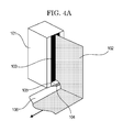
- the auxiliary liquid is sucked from the bottom edge of the curtain edge guide 101 so as to be collected.
- the coating liquid is also collected at the time when the auxiliary liquid is collected, and as a result, the deposit of the liquid 107 is accumulated on the claw 104 and suction port 105 of the curtain edge guide, as shown in FIG. 4C .
- the curtain film 102 supported by the edge of the claw is sifted to the holding part because of the presence of the deposits of the liquid, and at this time, the position of the curtain film is moved away from the position of the auxiliary liquid 103, the curtain film touches the frame of the edge guide (the flow speed of the edge of the curtain film becomes slow), and inward deviation of the curtain film 102 occurs.
- the problem occurs such that the deposition amount of the edge part relative to the coating width direction becomes large. Therefore, product loss increases as the coating width is not uniformed at the time of the production.
- the deposition amount of the edge relative to the coating width direction is large, non-dry portions are generated due to inferior drying in the production.
- the coating liquid is adhered to the conveyance roll of the web during the production, and thereafter the adhered coating liquid may contaminate the surface of the web coated film, or may cause blocking at the time when the final product is rolled up. Moreover, as the edge part is rose, the web may be cut or separated at the time of rolling up. Therefore, there has been a problem such that the production efficiency is lowered.
- FIG. 4A the arrow shows the conveyance direction of the web
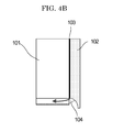
- FIG. 4B the arrow shows the suction of the auxiliary liquid
- FIG. 4C the arrows show the suction of the air, unless otherwise indicated.
- JP-A Japanese Patent Application Laid-Open
- JP-A No. 11-188299 discloses a curtain coating method in which a porous material is used for a curtain edge guide, and auxiliary liquid is evenly poured into the contact surface between the curtain edge guide and curtain coating liquid.
- JP-A No. 2001-46939 discloses a curtain coating method in which a plate glass is arranged at the contact surface between the curtain edge guide and curtain coating liquid.
- JP-A No. 2003-71353 discloses a curtain coating method in which the pressure of a space in the upstream side in the conveyance direction of a support member intercepted by the curtain film is reduced.
- the present invention has been made in view of the above problems inherent in the related art, and an object thereof is to provide a curtain coating apparatus and curtain coating method capable of preventing unstable motion of the coating liquid curtain film caused due to influence of air surrounding the end portion of the curtain film, preventing deposition of the coating liquid on the claw of the edge guide, and preventing inward deviation of the curtain film.
- a curtain coating apparatus and curtain coating method capable of preventing unstable swing of the curtain film caused by ambient air surrounding the end portion of the coating liquid curtain film, preventing deposition of the coating liquid on the claw of the edge guide, and preventing the inward deviation of the curtain film.
- the curtain coating apparatus of the present invention includes an ejection unit having a slit for ejecting coating liquid, a guide unit for guiding a coating liquid ejected from the slit in a curtain-like manner onto a support member , and a conveyance unit 6 for conveying the support member , and may further include other unit as necessary.
- the guide unit includes a curtain edge guide section provided at both edges of the coating liquid ejected in a curtain-like manner relative to the slit opening direction, and a windshield plate arranged so as to be in contact with the curtain edge guide section.
- the windshield plate is preferably (1) disposed so as to be parallel to the conveyance direction of the support member and vertical to the support member, or (2) disposed so as to be vertical to the conveyance direction of the support member and vertical to the support member.
- a length (width) of the windshield in the parallel direction to the support member is not particularly limited, and the windshield is disposed on the entire length (width) of the support member with respect to the horizontal direction.
- the length (width) of the windshield is preferably 10 mm or more, more preferably 10 mm to 30 mm.
- a length (height) of the windshield in the vertical direction to the support member is not particularly limited, and the windshield may be disposed entirely relative to the vertical direction to the support member.
- the length (height) of the windshield is preferably 10 mm or more, more preferably 10 mm to 60 mm.
- FIG. 5A is a schematic view showing a curtain coating apparatus according to a first embodiment of the present invention
- FIG. 5B is a schematic view showing the curtain coating apparatus according to a first embodiment of the present invention at the operation time.
- the coating liquid 3 is retained in a curtain coating head 1 which is the ejection unit having the slit.
- the coating liquid 3 is ejected from the curtain coating head 1 (allowed to freely fall) in the gravitational direction onto a web 5 which is the support member while being guided by a curtain edge guide 2 which is the curtain edge guide section provided at the both end portions of the coating liquid 3.
- the web 5 is conveyed in one direction at a constant speed by the conveyance unit including a backup roll 6 and other not-shown members.
- a vacuum unit 4 which is arranged on the upstream side in the conveyance direction of the web 5 relative to the curtain of the coating liquid 3, reduces the pressure of air in the space surrounded by the curtain edge guide 2, curtain of the coating liquid 3, web 5, and the like.
- the windshield plate 9 is arranged so as to be in contact with the curtain edge guide 2 and shields the end portion of the curtain of the coating liquid 3 from disturbed airflow.
- Reference numeral 3a denotes coating liquid (curtain film) and reference numeral 3b denotes coating liquid (on the web).
- the slit that the curtain coating head 1 has may have any shape as long as it can eject the coating liquid in a curtain-like manner.
- the slit has a rectangular cross-section with a sufficient length (in the slit opening direction) for the slit width.
- the slit width and slit length can arbitrarily be designed according to the viscosity or ejection amount of the coating liquid, the size of the web to be used, or the like.
- the curtain coating head 1 may have a plurality of slits. In this case, it is preferable that different coating liquids are ejected from the respective slits and coated onto the support member in a layered state.
- the curtain edge guide 2 may be of any kind as long as it can form the curtain film and may be a conventionally-known member.
- the coating liquid 3 may be of any kind as long as it can be formed into a curtain film and may be conventionally-known liquid.
- the vacuum unit 4 may be of any kind as long as it can suck air and reduce the pressure and may be a conventionally-known apparatus. Further, the conveyance unit including the backup roll 6 may be of any kind as long as it can convey the web 5 and may be a conventionally-known conveyance unit.
- the web 5 is a base material made of paper, film, or thin-film metal, whose surface is to be coated with coating liquid.
- the surface of the web 5 may be treated with a coating.
- FIG. 6A is a schematic perspective view of the curtain coating apparatus according to the first embodiment, showing a configuration of a portion around a curtain film end portion
- FIG. 6B is a schematic top view of the curtain coating apparatus according to the first embodiment, showing a configuration of a portion around a curtain film end portion.
- the windshield plate 9 is attached to the lower end of the curtain edge guide 2 on the opposite side in the conveyance direction of the web 5 relative to the coating liquid 3a flowing in a curtain-like manner.
- This configuration shields the end portion of the coating liquid curtain film 3a from disturbed airflow which is generated on the opposite side of the curtain edge guide 2 relative to the web conveyance direction to affect that portion, so that it is possible to prevent unstable swing of the curtain film 3a, thereby preventing inward deviation of the curtain film 3a at the curtain edge guide 2.
- the windshield plate 9 is arranged perpendicular both to the conveyance direction of the web 5 and web 5. This configuration is effective for shielding the end portion of the coating liquid curtain film 3a from disturbed airflow which is generated on the opposite side of the curtain edge guide 2 relative to the web conveyance direction to affect that portion, so that it is possible to prevent unstable swing of the curtain film 3a, thereby preventing inward deviation of the curtain film 3a at the curtain edge guide 2.
- metal such as iron, stainless steel, or aluminum and resin such as Teflon® or PET may be preferably used as a material of the windshield plate 9.
- the windshield plate 9 is preferably a plate-like member having a given width, height and thickness.
- the windshield plate 9 preferably has a length of 10 mm or more in the parallel direction (width direction of the windshield plate 9) to the web 5. This configuration is effective for shielding the end portion of the coating liquid curtain film 3a from disturbed airflow which is generated on the opposite side of the curtain edge guide 2 relative to the web conveyance direction to affect that portion, so that it is possible to prevent unstable swing of the curtain film 3a, thereby preventing inward deviation of the curtain film 3a at the curtain edge guide 2.
- the windshield plate 9 preferably has a length of 10 mm or more in the perpendicular direction (height direction of the windshield plate 9) to the web 5. This configuration is effective for shielding the end portion of the coating liquid curtain film 3a from disturbed airflow which is generated on the opposite side of the curtain edge guide 2 relative to the web conveyance direction to affect that portion, so that it is possible to prevent unstable swing of the curtain film 3a, thereby preventing inward deviation of the curtain film 3a at the curtain edge guide 2.
- the distance between the lower end (end portion at the web 5 side) of the curtain edge guide 2 and web 5 is preferably smaller than or equal to the distance between the lower end (end portion at the web 5 side) of the windshield plate 9 and web 5.
- the curtain edge guide 2 is preferably arranged closer to the web 5 than the windshield plate 9 by 0 mm to 10 mm. Namely, the distance between the curtain edge guide 2 and the web 5 is smaller than the distance between the windshield plate 9 and the web 5 by 0 mm to 10 mm.
- the curtain edge guide 2 cannot shield the end portion of the coating liquid curtain film 3a from disturbed airflow which is generated on the opposite side of the curtain edge guide 2 relative to the web conveyance direction to affect that portion, causing the curtain film 3a to swing and thereby inward deviation of the curtain film 3a at the curtain edge guide 2 occurs.
- FIG. 8 is a schematic top view of a configuration of a portion around a curtain film end portion in a first modification of the windshield plate of the curtain coating apparatus according to the present invention.
- the lower end of the windshield plate 9' (end portion at the web 5 side) in the present modification is inclined in a manner that a portion of the lower end is closer to the web 5 as the portion is close to the curtain edge guide 2.
- This configuration is effective to prevent the following problem. That is, as shown in FIG. 9 , when the coating liquid curtain film 3a is moved to the web position on the backup roll 6 at production start time, if the curtain film 3a swings at this time, the coating liquid 3 is brought into contact with and caught by the windshield plate 9'. The coating liquid 3 caught by the windshield plate 9' drops to the lower end thereof. The coating liquid 3 then drops onto the web 5 to cause defective coating (blocking and the like due to excessive deposition of the coating liquid). While, in the present modification, the coating liquid 3 caught by the windshield plate 9' is moved to the curtain edge guide 2 side due to the inclination of the lower end of the windshield plate 9', thereby avoiding the coating liquid 3 caught by the windshield plate 9' from dropping onto the web 5.
- the inclination angle of the windshield plate 9' is preferably 0.1° to 40°.
- the curtain edge guide 2 cannot shield the end portion of the coating liquid curtain film 3a from disturbed airflow which is generated on the opposite side of the curtain edge guide relative to the web conveyance direction to affect that portion, causing the curtain film 3a to swing and thereby inward deviation of the curtain film 3a at the curtain edge guide 2 occurs.
- FIG. 7 is a schematic perspective view of a configuration of a portion around a curtain film end portion in a second modification of the windshield plate of the curtain coating apparatus according to the present invention.
- the windshield plate 9 is arranged parallel to the conveyance direction of the web 5 and vertical to the web 5.
- This configuration shields the end portion of the coating liquid curtain film 3a from disturbed airflow which is generated on the opposite side of the curtain edge guide 2 relative to the web conveyance direction to affect that portion, so that it is possible to prevent unstable swing of the curtain film 3a, thereby preventing inward deviation of the curtain film 3a at the curtain edge guide 2.
- FIG. 10A is a schematic view showing a curtain coating apparatus according to a second embodiment of the present invention
- FIG. 10B is a schematic view showing the curtain coating apparatus according to a second embodiment of the present invention at the operation time.
- the guide unit has a slide surface 7 and, more preferably, a slide surface curtain edge guide section (slide portion edge guide) 8 is arranged at both end portions of the slide surface 7 relative to the slit opening direction.
- FIG. 2 The configuration shown in FIG. 2 can be applied without change to the slide surface 7 and slide surface curtain edge guide section 8.
- Configurations other than the slide surface 7 and slide surface curtain edge guide section 8 are the same as those of the curtain coating apparatus of the first embodiment, and the descriptions thereof are omitted here.
- a slide curtain coating head 1' which is an ejection unit having a slit, ejects coating liquid 3' on the slide surface 7, and the coating liquid 3' is layered on the slide surface 7.
- the ejected coating liquid 3' is slid on the slide surface 7 while being guided by the slide portion edge guide 8 which is the curtain edge guide section arranged at both end portions (slit longitudinal direction end portions in the drawings) of the layered coating liquid and then freely falls in the gravitational direction from the slide direction downstream end of the slide surface in a curtain-like manner.
- the coating liquid 3' is guided onto the web 5 which is the support member by the curtain edge guide 2 which is the curtain edge guide section arranged at both end portions of the curtain of the coating liquid 3'.
- the web 5 is conveyed in one direction at a constant speed by the conveyance unit including the backup roll 6 and other not-shown members.
- the vacuum unit 4 is arranged on the upstream side in the conveyance direction of the web 5 relative to the curtain of the coating liquid 3' and reduces the pressure of air in the space surrounded by the curtain edge guide 2, curtain of the coating liquid 3', web 5, and the like.
- the windshield plate 9 is arranged so as to be in contact with the curtain edge guide 2 and shields the end portion of the curtain of the coating liquid 3 from disturbed airflow caused at the time of conveyance of the web 5 or at the time of operation of the vacuum unit 4.
- the windshield plate 9 was attached to the lower end of the curtain edge guide 2 of the curtain coating apparatus as shown in FIG. 1 so as to be arranged parallel to the conveyance direction of the web 5 (vertical to the conveyance direction of the web) and vertical to the web 5 on the opposite side in the web conveyance direction relative to the coating liquid flowing in a curtain-like manner as shown in FIG. 6 .
- the coating liquid was coated on the web 5 (paper) at a coating speed of 400 m/min, with a coating width of 250 mm, and at a flow rate of coating liquid ejected from nozzle slit of 3,000 g/min.
- the dimension of the windshield plate 9 (PET film) was set to 30 mm width x 60 mm height x 175 ⁇ m thickness, the distance between the windshield plate 9 and web 5 was set equal to that between the curtain edge guide 2 and web 5, the vacuum pressure of the vacuum unit 4 was set to -3 kpa, and the volume of water flowing along the curtain edge guide 2 was set to 30 cc/min.
- the coating liquid had a viscosity of 300 mPa ⁇ s and a static surface tension of 35 mN/m.
- the composition of the coating liquid was as follows. (Coating liquid composition) Polyvinyl alcohol 85 parts Green pigment 5 parts Water 915 parts
- Example 1 The same coating procedure and evaluation as Example 1 were carried out using a slide curtain coating apparatus as shown in FIG. 2 . The result is shown in Table 1.
- the windshield plate 9 of the Example 2 was attached to the lower end of the curtain edge guide 2 so as to be arranged perpendicular (parallel to the conveyance direction of the web 5) both to the conveyance direction of the web 5 and web 5 on the opposite side in the conveyance direction of the web 5 relative to the coating liquid 3 flowing in a curtain-like manner, as shown in FIG. 7 , and the same coating procedure and evaluation as Example 2 were carried out.
- the result is shown in Table 1.
- Example 2 The same coating procedure and evaluation as Example 2 were carried out provided that the length (width) of the windshield plate 9 in the horizontal direction was set to 10 mm. The result is shown in Table 1.
- Example 2 The same coating procedure and evaluation as Example 2 were carried out provided that the length (width) of the windshield plate 9 in the horizontal direction was set to 5 mm. The result is shown in Table 1.
- Example 2 The same coating procedure and evaluation as Example 2 were carried out provided that the length (height) of the windshield plate 9 in the vertical direction was set to 10 mm. The result is shown in Table 1.
- Example 2 The same coating procedure and evaluation as Example 2 was carried out provided that the length (height) of the windshield plate 9 in the vertical direction was set to 5 mm. The result is shown in Table 1.
- Example 2 The same coating procedure and evaluation as Example 2 were carried out provided that the distance in the height direction between the windshield plate 9 and web 5 was made larger than the distance between the curtain edge guide 2 and web 5 by 5 mm. The result is shown in Table 1.
- Example 2 The same coating procedure and evaluation as Example 2 were carried out provided that the distance between the windshield plate 9 and web 5 was made smaller than the distance between the curtain edge guide 2 and web 5 by 10 mm. The result is shown in Table 1.
- Example 2 The same coating procedure and evaluation as Example 2 were carried out provided that the distance between the windshield plate 9 and web 5 was made larger than the distance between the curtain edge guide 2 and web 5 by 15 mm. The result is shown in Table 1.
- Example 2 The same coating procedure and evaluation as Example 2 were carried out provided that the distance between the windshield plate 9 and web 5 was made smaller than the distance between the curtain edge guide 2 and web 5 by 2 mm. The result is shown in Table 1.
- Example 2 The same coating procedure and evaluation as Example 2 were carried out provided that the lower end of the windshield plate 9 was inclined downward in the width direction toward the curtain edge guide 2 side at 40° as shown in FIG. 8 . The result is shown in Table 1.
- Example 2 The same coating procedure and evaluation as Example 2 were carried out provided that the lower end of the windshield plate 9 was inclined downward in the width direction toward the curtain edge guide 2 side at 45° as shown in FIG. 8 . The result is shown in Table 1.
- Example 2 The same coating procedure and evaluation as Example 2 were carried out provided that the lower end of the windshield plate 9 of Example 2 was inclined downward in the width direction toward the curtain edge guide 2 side at 1° as shown in FIG. 8 . The result is shown in Table 1.
- Example 1 Inward deviation of film at curtain end State of deposition on claw of edge guide Presence/absence Evaluation Example 1 Absent for 24 hours A A Example 2 Absent for 24 hours A A Example 3 Absent for 24 hours A A Example 4 Absent for 24 hours A A Example 5 Present after 2 hours B B Example 6 Absent for 24 hours A A Example 7 Present after 3 hours B B Example 8 Absent for 24 hours A A Example 9 Absent for 24 hours A B Example 10 Present after 2 hours B B Example 11 Present after 3 hours B B Example 12 Absent for 24 hours A A Example 13 Present after 3 hours B B Example 14 Absent for 24 hours A A Comparative Example 1 Present after 1 hour C C Comparative Example 2 Present after 1 hour C C
Landscapes
- Coating Apparatus (AREA)
- Application Of Or Painting With Fluid Materials (AREA)
Abstract
Description
- The present invention relates to a curtain coating apparatus and a curtain coating method and, more particularly, to a curtain coating apparatus and its method capable of preventing a curtain film from swinging, suppressing liquid from depositing on a claw of an edge guide, and suppressing inward deviation of a curtain film.
- A curtain coating method is widely used in production of a photographic sensitive material such as a photographic film. As the curtain coating method, the following methods are known. One is a method as shown in
FIG. 1 , wherein coatingliquid 3 ejected from a nozzle slit is allowed to freely fall in a curtain-like manner by acurtain edge guide 2 against a continuously runningweb 5 to thereby form a coating film. Another is a method as shown inFIG. 2 , wherein coatingliquid 3 ejected from a nozzle slit is allowed to move on aslide surface 7 and then to freely fall in a curtain-like manner by a curtain edge guide 2' against a continuously runningweb 5 to thereby form a coating film. Further, as a multilayer coating method, the following methods are known. One is a method wherein coating liquids having different functions ejected from respective nozzle slits are allowed to freely fall in a curtain-like manner by a curtain edge guide against a continuously running web to thereby form a coating film. Another is a method wherein coating liquids having different functions ejected from respective nozzle slits are allowed to be layered on a slide surface, and the layered liquids are then allowed to freely fall in a curtain-like manner by a curtain edge guide against a continuously running web to thereby form a coating film. - Note that, in
FIGs. 1 and2 , thereference numerals - However, the following disadvantages are found in the method described above. As shown in
FIGs. 1 and2 , thevacuum unit 4 is arranged at a portion opposite to the conveyance direction of thecurtain coating liquid 3 on theweb 5. Thevacuum unit 4 sucks in air entrained by the runningweb 5 in order to prevent occurrence of air entrainment phenomenon (phenomenon that air entrained by the conveyedweb 5 is trapped in thecoating liquid 3 coated on theweb 5 at the transfer section of thecoating liquid 3 on theweb 5 to become air bubbles). Thus, as shown inFIG. 3 , ambient air is sucked (denoted by upward solid arrows inFIG. 3 ) by thevacuum unit 4 at the end portion of the coating liquid curtain film 3a, while ambient air is entrained by the conveyed web 5 (denoted by downward solid arrows inFIG. 3 ), causing air flow in the direction denoted by broken arrows inFIG. 3 . As a result, the coating liquid curtain 3a becomes unstable, causing the same to swing. Then, the coating liquid is isolated from thecurtain edge guide 2, and the coating liquid curtain film 3a is inwardly deviated, with the result that the coating width becomes unstable. Further, this inward deviation causes excessive deposition of the coating liquid at the end portion in the coating width direction. Therefore, product loss increases due to uneven coating width during production. In addition, when the deposition of the coating liquid becomes excessive at the end portion in the coating width direction, undried portion appears during production due to defective drying, causing attachment of the coating liquid to a web conveying roll during production. This then causes the subsequent web coating surface to be polluted, causes blocking at the winding time of the product, or causes the web to be cut at the winding time due to elevation of the end portion, thereby reducing production efficiency. Note that, inFIG. 3 , thereference numerals - In the curtain coating as shown in
FIG. 4A , thecurtain edge guide 101 for guiding the coating liquid in the form of a curtain allows, for the purpose of stabilizing thecurtain film 102, anauxiliary liquid 103 to flow so that the flow rate of the edge of the curtain film becomes close to that of the center of the curtain film. The auxiliary liquid is sucked from the bottom edge of thecurtain edge guide 101 so as to be collected. However, the coating liquid is also collected at the time when the auxiliary liquid is collected, and as a result, the deposit of theliquid 107 is accumulated on theclaw 104 andsuction port 105 of the curtain edge guide, as shown inFIG. 4C . This is because there is a part in the air flow where is faster than the other parts caused by the air suction on the side of the web conveyance direction of thecurtain film 102 at the coating liquid contacting surface of the claw and on the air-liquid interface on the other side at the time of the collection of the auxiliary liquid. Therefore, the flow of the coating liquid becomes slow at the contacting part with the claw, and the coating liquid of slow flow is dried. Moreover, as the swing of thecurtain film 102 is large, the amount of the deposits of theliquid 107 becomes large at the bottom claw of thecurtain edge guide 101 with time in the continuous production. Then, thecurtain film 102 supported by the edge of the claw is sifted to the holding part because of the presence of the deposits of the liquid, and at this time, the position of the curtain film is moved away from the position of theauxiliary liquid 103, the curtain film touches the frame of the edge guide (the flow speed of the edge of the curtain film becomes slow), and inward deviation of thecurtain film 102 occurs. As a result of this, the problem occurs such that the deposition amount of the edge part relative to the coating width direction becomes large. Therefore, product loss increases as the coating width is not uniformed at the time of the production. Moreover, as the deposition amount of the edge relative to the coating width direction is large, non-dry portions are generated due to inferior drying in the production. As a result, the coating liquid is adhered to the conveyance roll of the web during the production, and thereafter the adhered coating liquid may contaminate the surface of the web coated film, or may cause blocking at the time when the final product is rolled up. Moreover, as the edge part is rose, the web may be cut or separated at the time of rolling up. Therefore, there has been a problem such that the production efficiency is lowered. - Note that, in
FIG. 4A the arrow shows the conveyance direction of the web, inFIG. 4B the arrow shows the suction of the auxiliary liquid, andFIG. 4C the arrows show the suction of the air, unless otherwise indicated. - In order to prevent such swing and inward deviation of the coating liquid curtain film, the following methods have been proposed. Japanese Patent Application Laid-Open (JP-A) No.
11-188299 JP-A No. 2001-46939 JP-A No. 2003-71353 - However, in the above curtain coating methods disclosed in
JP-A Nos. 11-188299 2001-46939 2003-71353 - The present invention has been made in view of the above problems inherent in the related art, and an object thereof is to provide a curtain coating apparatus and curtain coating method capable of preventing unstable motion of the coating liquid curtain film caused due to influence of air surrounding the end portion of the curtain film, preventing deposition of the coating liquid on the claw of the edge guide, and preventing inward deviation of the curtain film.
- Means for solving the above problems are as follows:
- <1> A curtain coating apparatus, containing: an ejection unit having a slit for ejecting coating liquid; a guide unit configured to guide the coating liquid ejected from the slit onto a support member in a curtain-like manner; and a conveyance unit configured to convey the support member, wherein the guide unit contains a curtain edge guide section provided at both end portions of the coating liquid ejected in a curtain-like manner relative to an opening direction of the slit, and a windshield plate arranged so as to be in contact with the curtain edge guide section.
- <2> The curtain coating apparatus according to <1>, wherein the guide unit contains a slide surface, and the ejection unit ejects the coating liquid onto the slide surface.
- <3> The curtain coating apparatus according to <2>, wherein the guide unit contains a slide surface curtain edge guide section at both end portions of the slide surface relative to an opening direction of the slit.
- <4> The curtain coating apparatus according to any one of <1> to <3>, wherein the ejection unit contains a plurality of slits.
- <5> The curtain coating apparatus according to any one of <1> to <4>, wherein the windshield plate is arranged on the opposite side of the curtain edge guide section relative to a conveyance direction of the support member.
- <6> The curtain coating apparatus according to <5>, wherein the windshield plate is arranged parallel to the conveyance direction of the support member and perpendicular to the support member.
- <7> The curtain coating apparatus according to <5>, wherein the windshield plate is arranged perpendicular both to the conveyance direction of the support member and the support member.
- <8> The curtain coating apparatus according to any one of <1> to <7>, wherein the windshield plate has a length of 10 mm or more in the parallel direction to the support member.
- <9> The curtain coating apparatus according to any one of <1> to <8>, wherein the windshield plate has a length of 10 mm or more in the perpendicular direction to the support member.
- <10> The curtain coating apparatus according to any one of <1> to <9>, wherein the distance between the curtain edge guide section and the support member is smaller than or equal to the distance between the windshield plate and the support member.
- <11> The curtain coating apparatus according to <10>, wherein the distance between the curtain edge guide section and the support member is smaller than the distance between the windshield plate and the support member by 0 mm to 10 mm.
- <12> The curtain coating apparatus according to any one of <1> to <11>, wherein a lower end of the windshield plate at the support member side is inclined such that a portion of the lower end closer to the curtain edge guide section is closer to the support member.
- <13> The curtain coating apparatus according to <12>, wherein the inclination angle of the lower end of the windshield plate is 0.1° to 40°.
- <14> A curtain coating method, containing: ejecting coating liquid from a slit; guiding the coating liquid ejected from the slit onto a support member in a curtain-like manner by means of a guide unit ; and conveying the support member, wherein the guide unit contains a curtain edge guide section provided at both end portions of the coating liquid ejected in a curtain-like manner relative to an opening direction of the slit, and a windshield plate arranged so as to be in contact with the curtain edge guide section.
- <15> The curtain coating method according to <14>, wherein the guide unit contains a slide surface, and the ejecting is to eject the coating liquid onto the slide surface.
- <16> The curtain coating method according to <15>, wherein the guide unit contains a slide surface curtain edge guide section at both end portions of the slide surface relative to an opening direction of the slit.
- <17> The curtain coating method according to any one of <14> to <16>, wherein the ejecting is to eject the coating liquids from a plurality of slits.
- <18> The curtain coating method according to any one of <14> to <17>, wherein the windshield plate is arranged on the opposite side of the curtain edge guide section relative to a conveyance direction of the support member.
- <19> The curtain coating method according to <18>, wherein the windshield plate is arranged parallel to the conveyance direction of the support member and perpendicular to the support member.
- <20> The curtain coating method according to <18>, wherein the windshield plate is arranged perpendicular both to the conveyance direction of the support member and the support member.
- <21> The curtain coating method according to any one of <14> to <20>, wherein the windshield plate has a length of 10 mm or more in the parallel direction to the support member.
- <22> The curtain coating method according to any one of <14> to <21>, wherein the windshield plate has a length of 10 mm or more in the perpendicular direction to the support member.
- <23> The curtain coating method according to any one of <14> to <22>, wherein the distance between the curtain edge guide section and the support member is smaller than or equal to the distance between the windshield plate and the support member.
- <24> The curtain coating method according to <23>, wherein the distance between the curtain edge guide section and the support member is smaller than the distance between the windshield plate and the support member by 0 mm to 10 mm.
- <25> The curtain coating method according to any one of <14> to <24>, wherein a lower end of the windshield plate at the support member side is inclined such that a portion of the lower end closer to the curtain edge guide section is closer to the support member.
- <26> The curtain coating method according to <25>, wherein the inclination angle of the lower end of the windshield plate is 0.1° to 40°.
- According to the present invention, a curtain coating apparatus and curtain coating method capable of preventing unstable swing of the curtain film caused by ambient air surrounding the end portion of the coating liquid curtain film, preventing deposition of the coating liquid on the claw of the edge guide, and preventing the inward deviation of the curtain film.
-
-
FIG. 1 is a cross-sectional perspective view of a configuration example of a conventional curtain coating apparatus; -
FIG. 2 is a cross-sectional perspective view of another configuration example of a conventional curtain coating apparatus; -
FIG. 3 is a top view of a conventional curtain coating apparatus, showing a configuration of a portion around a coating liquid curtain film end portion; -
FIG. 4A is a perspective view showing a conventional curtain coating apparatus; -
FIG. 4B is an enlarged partial view ofFIG. 4A ; -
FIG. 4C is a diagram explaining a mechanism for forming deposition on a claw during the curtain coating; -
FIG. 5A is a schematic view showing a curtain coating apparatus according to a first embodiment of the present invention; -
FIG. 5B is a schematic view showing the curtain coating apparatus according to the first embodiment of the present invention at the operation time; -
FIG. 6A is a schematic perspective view of the curtain coating apparatus according to the first embodiment, showing a configuration of a portion around a curtain film end portion; -
FIG. 6B is a schematic top view of the curtain coating apparatus according to the first embodiment, showing a configuration of a portion around a curtain film end portion; -
FIG. 7 is a schematic top view of a configuration of a portion around a curtain film end portion in a second modification of a windshield plate of the curtain coating apparatus according to the present invention; -
FIG. 8 is a schematic perspective view of a configuration of a portion around a curtain film end portion in a first modification of a windshield plate of the curtain coating apparatus according to the present invention; -
FIG. 9 is a view for explaining a state of the curtain edge guide and migration of the coating liquid during production; -
FIG. 10A is a schematic view showing a curtain coating apparatus according to a second embodiment of the present invention; -
FIG. 10B is a schematic view showing the curtain coating apparatus according to the second embodiment of the present invention at the operation time; -
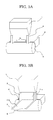
FIG. 11A is a view for explaining a state of "absence of inward deviation" in Table 1; and -
FIG. 11B is a view for explaining a state of "presence of inward deviation" in Table 1. - The curtain coating apparatus of the present invention includes an ejection unit having a slit for ejecting coating liquid, a guide unit for guiding a coating liquid ejected from the slit in a curtain-like manner onto a support member , and a
conveyance unit 6 for conveying the support member , and may further include other unit as necessary. - The guide unit includes a curtain edge guide section provided at both edges of the coating liquid ejected in a curtain-like manner relative to the slit opening direction, and a windshield plate arranged so as to be in contact with the curtain edge guide section.
- The windshield plate is preferably (1) disposed so as to be parallel to the conveyance direction of the support member and vertical to the support member, or (2) disposed so as to be vertical to the conveyance direction of the support member and vertical to the support member.
- A length (width) of the windshield in the parallel direction to the support member is not particularly limited, and the windshield is disposed on the entire length (width) of the support member with respect to the horizontal direction. The length (width) of the windshield is preferably 10 mm or more, more preferably 10 mm to 30 mm.
- A length (height) of the windshield in the vertical direction to the support member is not particularly limited, and the windshield may be disposed entirely relative to the vertical direction to the support member. The length (height) of the windshield is preferably 10 mm or more, more preferably 10 mm to 60 mm.
- Hereinafter, the curtain coating apparatus of the present invention will be described in more detail with reference to the accompanying drawings.
- The following embodiments are preferred embodiments of the present invention, and various limitations which are technically preferable are employed. However, the present invention is not limited to the following aspects unless otherwise indicated.
-
FIG. 5A is a schematic view showing a curtain coating apparatus according to a first embodiment of the present invention, andFIG. 5B is a schematic view showing the curtain coating apparatus according to a first embodiment of the present invention at the operation time. - The
coating liquid 3 is retained in acurtain coating head 1 which is the ejection unit having the slit. Thecoating liquid 3 is ejected from the curtain coating head 1 (allowed to freely fall) in the gravitational direction onto aweb 5 which is the support member while being guided by acurtain edge guide 2 which is the curtain edge guide section provided at the both end portions of thecoating liquid 3. Theweb 5 is conveyed in one direction at a constant speed by the conveyance unit including abackup roll 6 and other not-shown members. At this time, avacuum unit 4, which is arranged on the upstream side in the conveyance direction of theweb 5 relative to the curtain of thecoating liquid 3, reduces the pressure of air in the space surrounded by thecurtain edge guide 2, curtain of thecoating liquid 3,web 5, and the like. Thewindshield plate 9 is arranged so as to be in contact with thecurtain edge guide 2 and shields the end portion of the curtain of thecoating liquid 3 from disturbed airflow. Reference numeral 3a denotes coating liquid (curtain film) and reference numeral 3b denotes coating liquid (on the web). - The slit that the
curtain coating head 1 has may have any shape as long as it can eject the coating liquid in a curtain-like manner. Preferably, the slit has a rectangular cross-section with a sufficient length (in the slit opening direction) for the slit width. The slit width and slit length can arbitrarily be designed according to the viscosity or ejection amount of the coating liquid, the size of the web to be used, or the like. - Further, the
curtain coating head 1 may have a plurality of slits. In this case, it is preferable that different coating liquids are ejected from the respective slits and coated onto the support member in a layered state. - In the present invention, the
curtain edge guide 2 may be of any kind as long as it can form the curtain film and may be a conventionally-known member. - Further, in the present invention, the
coating liquid 3 may be of any kind as long as it can be formed into a curtain film and may be conventionally- known liquid. - The
vacuum unit 4 may be of any kind as long as it can suck air and reduce the pressure and may be a conventionally-known apparatus. Further, the conveyance unit including thebackup roll 6 may be of any kind as long as it can convey theweb 5 and may be a conventionally-known conveyance unit. - The
web 5 is a base material made of paper, film, or thin-film metal, whose surface is to be coated with coating liquid. The surface of theweb 5 may be treated with a coating. -
FIG. 6A is a schematic perspective view of the curtain coating apparatus according to the first embodiment, showing a configuration of a portion around a curtain film end portion, andFIG. 6B is a schematic top view of the curtain coating apparatus according to the first embodiment, showing a configuration of a portion around a curtain film end portion. - As shown in
FIGs. 6A and 6B , thewindshield plate 9 is attached to the lower end of thecurtain edge guide 2 on the opposite side in the conveyance direction of theweb 5 relative to the coating liquid 3a flowing in a curtain-like manner. This configuration shields the end portion of the coating liquid curtain film 3a from disturbed airflow which is generated on the opposite side of thecurtain edge guide 2 relative to the web conveyance direction to affect that portion, so that it is possible to prevent unstable swing of the curtain film 3a, thereby preventing inward deviation of the curtain film 3a at thecurtain edge guide 2. - In the present embodiment, the
windshield plate 9 is arranged perpendicular both to the conveyance direction of theweb 5 andweb 5. This configuration is effective for shielding the end portion of the coating liquid curtain film 3a from disturbed airflow which is generated on the opposite side of thecurtain edge guide 2 relative to the web conveyance direction to affect that portion, so that it is possible to prevent unstable swing of the curtain film 3a, thereby preventing inward deviation of the curtain film 3a at thecurtain edge guide 2. - Although not particularly limited, metal such as iron, stainless steel, or aluminum and resin such as Teflon® or PET may be preferably used as a material of the
windshield plate 9. - The
windshield plate 9 is preferably a plate-like member having a given width, height and thickness. - Further, the
windshield plate 9 preferably has a length of 10 mm or more in the parallel direction (width direction of the windshield plate 9) to theweb 5. This configuration is effective for shielding the end portion of the coating liquid curtain film 3a from disturbed airflow which is generated on the opposite side of thecurtain edge guide 2 relative to the web conveyance direction to affect that portion, so that it is possible to prevent unstable swing of the curtain film 3a, thereby preventing inward deviation of the curtain film 3a at thecurtain edge guide 2. - Further, the
windshield plate 9 preferably has a length of 10 mm or more in the perpendicular direction (height direction of the windshield plate 9) to theweb 5. This configuration is effective for shielding the end portion of the coating liquid curtain film 3a from disturbed airflow which is generated on the opposite side of thecurtain edge guide 2 relative to the web conveyance direction to affect that portion, so that it is possible to prevent unstable swing of the curtain film 3a, thereby preventing inward deviation of the curtain film 3a at thecurtain edge guide 2. - Further, the distance between the lower end (end portion at the
web 5 side) of thecurtain edge guide 2 andweb 5 is preferably smaller than or equal to the distance between the lower end (end portion at theweb 5 side) of thewindshield plate 9 andweb 5. With this configuration, the size of a gap between the lower end of thecurtain edge guide 2 andweb 5 can be reduced and thereby reducing entrance of ambient air, so that it is possible to prevent unstable swing of the curtain film 3a, thereby preventing inward deviation of the curtain film 3a at thecurtain edge guide 2. - Further, the
curtain edge guide 2 is preferably arranged closer to theweb 5 than thewindshield plate 9 by 0 mm to 10 mm. Namely, the distance between thecurtain edge guide 2 and theweb 5 is smaller than the distance between thewindshield plate 9 and theweb 5 by 0 mm to 10 mm. When thecurtain edge guide 2 is further away from theweb 5 than thewindshield plate 9 by a distance of 10 mm or more, thecurtain edge guide 2 cannot shield the end portion of the coating liquid curtain film 3a from disturbed airflow which is generated on the opposite side of thecurtain edge guide 2 relative to the web conveyance direction to affect that portion, causing the curtain film 3a to swing and thereby inward deviation of the curtain film 3a at thecurtain edge guide 2 occurs. -
FIG. 8 is a schematic top view of a configuration of a portion around a curtain film end portion in a first modification of the windshield plate of the curtain coating apparatus according to the present invention. - The lower end of the windshield plate 9' (end portion at the
web 5 side) in the present modification is inclined in a manner that a portion of the lower end is closer to theweb 5 as the portion is close to thecurtain edge guide 2. - This configuration is effective to prevent the following problem. That is, as shown in
FIG. 9 , when the coating liquid curtain film 3a is moved to the web position on thebackup roll 6 at production start time, if the curtain film 3a swings at this time, thecoating liquid 3 is brought into contact with and caught by the windshield plate 9'. Thecoating liquid 3 caught by the windshield plate 9' drops to the lower end thereof. Thecoating liquid 3 then drops onto theweb 5 to cause defective coating (blocking and the like due to excessive deposition of the coating liquid). While, in the present modification, thecoating liquid 3 caught by the windshield plate 9' is moved to thecurtain edge guide 2 side due to the inclination of the lower end of the windshield plate 9', thereby avoiding thecoating liquid 3 caught by the windshield plate 9' from dropping onto theweb 5. - In this case, the inclination angle of the windshield plate 9' is preferably 0.1° to 40°. When the inclination angle is more than 40°, the
curtain edge guide 2 cannot shield the end portion of the coating liquid curtain film 3a from disturbed airflow which is generated on the opposite side of the curtain edge guide relative to the web conveyance direction to affect that portion, causing the curtain film 3a to swing and thereby inward deviation of the curtain film 3a at thecurtain edge guide 2 occurs. -
FIG. 7 is a schematic perspective view of a configuration of a portion around a curtain film end portion in a second modification of the windshield plate of the curtain coating apparatus according to the present invention. - In this modification, the
windshield plate 9 is arranged parallel to the conveyance direction of theweb 5 and vertical to theweb 5. This configuration shields the end portion of the coating liquid curtain film 3a from disturbed airflow which is generated on the opposite side of thecurtain edge guide 2 relative to the web conveyance direction to affect that portion, so that it is possible to prevent unstable swing of the curtain film 3a, thereby preventing inward deviation of the curtain film 3a at thecurtain edge guide 2. (Second embodiment; modification of curtain coating apparatus) -
FIG. 10A is a schematic view showing a curtain coating apparatus according to a second embodiment of the present invention, andFIG. 10B is a schematic view showing the curtain coating apparatus according to a second embodiment of the present invention at the operation time. - Preferably, the guide unit has a
slide surface 7 and, more preferably, a slide surface curtain edge guide section (slide portion edge guide) 8 is arranged at both end portions of theslide surface 7 relative to the slit opening direction. - The configuration shown in
FIG. 2 can be applied without change to theslide surface 7 and slide surface curtainedge guide section 8. Configurations other than theslide surface 7 and slide surface curtainedge guide section 8 are the same as those of the curtain coating apparatus of the first embodiment, and the descriptions thereof are omitted here. - Hereinafter, with reference to
FIGs. 10A and 10B , a configuration of the curtain coating apparatus according to the second embodiment will be described. - In the present embodiment, a slide curtain coating head 1', which is an ejection unit having a slit, ejects coating liquid 3' on the
slide surface 7, and the coating liquid 3' is layered on theslide surface 7. The ejected coating liquid 3' is slid on theslide surface 7 while being guided by the slideportion edge guide 8 which is the curtain edge guide section arranged at both end portions (slit longitudinal direction end portions in the drawings) of the layered coating liquid and then freely falls in the gravitational direction from the slide direction downstream end of the slide surface in a curtain-like manner. At this time, the coating liquid 3' is guided onto theweb 5 which is the support member by thecurtain edge guide 2 which is the curtain edge guide section arranged at both end portions of the curtain of the coating liquid 3'. Theweb 5 is conveyed in one direction at a constant speed by the conveyance unit including thebackup roll 6 and other not-shown members. Thevacuum unit 4 is arranged on the upstream side in the conveyance direction of theweb 5 relative to the curtain of the coating liquid 3' and reduces the pressure of air in the space surrounded by thecurtain edge guide 2, curtain of the coating liquid 3',web 5, and the like. Further, thewindshield plate 9 is arranged so as to be in contact with thecurtain edge guide 2 and shields the end portion of the curtain of thecoating liquid 3 from disturbed airflow caused at the time of conveyance of theweb 5 or at the time of operation of thevacuum unit 4. - Hereinafter, the present invention will be described in more detail with reference to Examples and Comparative Examples, which however shall not be construed as limiting the scope of the present invention in any way. Parts used in the examples mean parts by mass.
- The
windshield plate 9 was attached to the lower end of thecurtain edge guide 2 of the curtain coating apparatus as shown inFIG. 1 so as to be arranged parallel to the conveyance direction of the web 5 (vertical to the conveyance direction of the web) and vertical to theweb 5 on the opposite side in the web conveyance direction relative to the coating liquid flowing in a curtain-like manner as shown inFIG. 6 . The coating liquid was coated on the web 5 (paper) at a coating speed of 400 m/min, with a coating width of 250 mm, and at a flow rate of coating liquid ejected from nozzle slit of 3,000 g/min. - The dimension of the windshield plate 9 (PET film) was set to 30 mm width x 60 mm height x 175 µm thickness, the distance between the
windshield plate 9 andweb 5 was set equal to that between thecurtain edge guide 2 andweb 5, the vacuum pressure of thevacuum unit 4 was set to -3 kpa, and the volume of water flowing along thecurtain edge guide 2 was set to 30 cc/min. - The coating liquid had a viscosity of 300 mPa·s and a static surface tension of 35 mN/m. The composition of the coating liquid was as follows.
(Coating liquid composition) Polyvinyl alcohol 85 parts Green pigment 5 parts Water 915 parts - Then, presence/absence of the inward deviation of the curtain film at the
curtain edge guide 2 and the state of the deposition on the claw of the curtain edge guide were evaluated under the above coating conditions. The result is shown in Table 1. -
- A: No inward deviation of the curtain film for 24 hours
- B: Occurrence of the inward deviation after 2 to 3 hours
- C: Occurrence of the inward deviation after 1 hour
-
- A: Very small amount of the deposition on the claw
- B: Small amount of the deposition on the claw
- C: Large amount of the deposition on the claw
- The same coating procedure and evaluation as Example 1 were carried out using a slide curtain coating apparatus as shown in
FIG. 2 . The result is shown in Table 1. - The
windshield plate 9 of the Example 2 was attached to the lower end of thecurtain edge guide 2 so as to be arranged perpendicular (parallel to the conveyance direction of the web 5) both to the conveyance direction of theweb 5 andweb 5 on the opposite side in the conveyance direction of theweb 5 relative to thecoating liquid 3 flowing in a curtain-like manner, as shown inFIG. 7 , and the same coating procedure and evaluation as Example 2 were carried out. The result is shown in Table 1. - The same coating procedure and evaluation as Example 2 were carried out provided that the length (width) of the
windshield plate 9 in the horizontal direction was set to 10 mm. The result is shown in Table 1. - The same coating procedure and evaluation as Example 2 were carried out provided that the length (width) of the
windshield plate 9 in the horizontal direction was set to 5 mm. The result is shown in Table 1. - The same coating procedure and evaluation as Example 2 were carried out provided that the length (height) of the
windshield plate 9 in the vertical direction was set to 10 mm. The result is shown in Table 1. - The same coating procedure and evaluation as Example 2 was carried out provided that the length (height) of the
windshield plate 9 in the vertical direction was set to 5 mm. The result is shown in Table 1. - The same coating procedure and evaluation as Example 2 were carried out provided that the distance in the height direction between the
windshield plate 9 andweb 5 was made larger than the distance between thecurtain edge guide 2 andweb 5 by 5 mm. The result is shown in Table 1. - The same coating procedure and evaluation as Example 2 were carried out provided that the distance between the
windshield plate 9 andweb 5 was made smaller than the distance between thecurtain edge guide 2 andweb 5 by 10 mm. The result is shown in Table 1. - The same coating procedure and evaluation as Example 2 were carried out provided that the distance between the
windshield plate 9 andweb 5 was made larger than the distance between thecurtain edge guide 2 andweb 5 by 15 mm. The result is shown in Table 1. - The same coating procedure and evaluation as Example 2 were carried out provided that the distance between the
windshield plate 9 andweb 5 was made smaller than the distance between thecurtain edge guide 2 andweb 5 by 2 mm. The result is shown in Table 1. - The same coating procedure and evaluation as Example 2 were carried out provided that the lower end of the
windshield plate 9 was inclined downward in the width direction toward thecurtain edge guide 2 side at 40° as shown inFIG. 8 . The result is shown in Table 1. - The same coating procedure and evaluation as Example 2 were carried out provided that the lower end of the
windshield plate 9 was inclined downward in the width direction toward thecurtain edge guide 2 side at 45° as shown inFIG. 8 . The result is shown in Table 1. - The same coating procedure and evaluation as Example 2 were carried out provided that the lower end of the
windshield plate 9 of Example 2 was inclined downward in the width direction toward thecurtain edge guide 2 side at 1° as shown inFIG. 8 . The result is shown in Table 1. - The same coating procedure and evaluation as Example 1 were carried out provided that the
windshield plate 9 was removed from the apparatus. The result is shown in Table 1. - The same coating procedure and evaluation as Example 2 were carried out provided that the
windshield plate 9 removed from the apparatus. The result is shown in Table 1.Table 1 Inward deviation of film at curtain end State of deposition on claw of edge guide Presence/absence Evaluation Example 1 Absent for 24 hours A A Example 2 Absent for 24 hours A A Example 3 Absent for 24 hours A A Example 4 Absent for 24 hours A A Example 5 Present after 2 hours B B Example 6 Absent for 24 hours A A Example 7 Present after 3 hours B B Example 8 Absent for 24 hours A A Example 9 Absent for 24 hours A B Example 10 Present after 2 hours B B Example 11 Present after 3 hours B B Example 12 Absent for 24 hours A A Example 13 Present after 3 hours B B Example 14 Absent for 24 hours A A Comparative Example 1 Present after 1 hour C C Comparative Example 2 Present after 1 hour C C - The states of absence and presence of the inward deviation in Table 1 are explained in
FIGs. 11A and 11B . - The results of the above Examples 1 to 14 and Comparative Examples 1 and 2 reveal that the curtain coating apparatus of the present invention can prevent unstable swing of the curtain film caused by ambient air surrounding the end portion of the coating liquid curtain film, prevent the coating liquid from depositing on the claw of the edge guide, and prevent the inward deviation of the curtain film.
Claims (14)
- A curtain coating apparatus, comprising:an ejection unit having a slit for ejecting coating liquid;a guide unit configured to guide the coating liquid ejected from the slit onto a support member in a curtain-like manner; anda conveyance unit configured to convey the support member, wherein the guide unit comprises a curtain edge guide section provided at both end portions of the coating liquid ejected in a curtain-like manner relative to an opening direction of the slit, and a windshield plate arranged so as to be in contact with the curtain edge guide section.
- The curtain coating apparatus according to claim 1, wherein the guide unit comprises a slide surface, and the ejection unit ejects the coating liquid onto the slide surface.
- The curtain coating apparatus according to claim 2, wherein the guide unit comprises a slide surface curtain edge guide section at both end portions of the slide surface relative to an opening direction of the slit.
- The curtain coating apparatus according to any one of claims 1 to 3, wherein the ejection unit comprises a plurality of slits.
- The curtain coating apparatus according to any one of claims 1 to 4, wherein the windshield plate is arranged on the opposite side of the curtain edge guide section relative to a conveyance direction of the support member.
- The curtain coating apparatus according to claim 5, wherein the windshield plate is arranged parallel to the conveyance direction of the support member and perpendicular to the support member.
- The curtain coating apparatus according to claim 5, wherein the windshield plate is arranged perpendicular both to the conveyance direction of the support member and the support member.
- The curtain coating apparatus according to any one of claims 1 to 7, wherein the windshield plate has a length of 10 mm or more in the parallel direction to the support member.
- The curtain coating apparatus according to any one of claims 1 to 8, wherein the windshield plate has a length of 10 mm or more in the perpendicular direction to the support member.
- The curtain coating apparatus according to any one of claims 1 to 9, wherein the distance between the curtain edge guide section and the support member is smaller than or equal to the distance between the windshield plate and the support member.
- The curtain coating apparatus according to claim 10, wherein the distance between the curtain edge guide section and the support member is smaller than the distance between the windshield plate and the support member by 0 mm to 10 mm.
- The curtain coating apparatus according to any one of claims 1 to 11, wherein a lower end of the windshield plate at the support member side is inclined such that a portion of the lower end closer to the curtain edge guide section is closer to the support member.
- The curtain coating apparatus according to claim 12, wherein the inclination angle of the lower end of the windshield plate is 0.1° to 40°.
- A curtain coating method, comprising:ejecting coating liquid from a slit;guiding the coating liquid ejected from the slit onto a support member in a curtain-like manner by means of a guide unlit andconveying the support member,wherein the guide unit comprises a curtain edge guide section provided at both end portions of the coating liquid ejected in a curtain-like manner relative to an opening direction of the slit, and a windshield plate arranged so as to be in contact with the curtain edge guide section.
Applications Claiming Priority (1)
| Application Number | Priority Date | Filing Date | Title |
|---|---|---|---|
| JP2008068544 | 2008-03-17 |
Publications (2)
| Publication Number | Publication Date |
|---|---|
| EP2103357A1 true EP2103357A1 (en) | 2009-09-23 |
| EP2103357B1 EP2103357B1 (en) | 2013-02-20 |
Family
ID=40602145
Family Applications (1)
| Application Number | Title | Priority Date | Filing Date |
|---|---|---|---|
| EP20090155244 Ceased EP2103357B1 (en) | 2008-03-17 | 2009-03-16 | Curtain coating apparatus and curtain coating method |
Country Status (3)
| Country | Link |
|---|---|
| EP (1) | EP2103357B1 (en) |
| JP (1) | JP5439880B2 (en) |
| CN (1) | CN101537402B (en) |
Cited By (2)
| Publication number | Priority date | Publication date | Assignee | Title |
|---|---|---|---|---|
| WO2011073094A1 (en) * | 2009-12-16 | 2011-06-23 | Voith Patent Gmbh | Curtain application mechanism |
| EP2505270A1 (en) * | 2011-03-31 | 2012-10-03 | Ricoh Company, Ltd. | Curtain coating method and curtain coating device |
Families Citing this family (4)
| Publication number | Priority date | Publication date | Assignee | Title |
|---|---|---|---|---|
| CN102337705B (en) * | 2010-07-20 | 2013-07-31 | 中国制浆造纸研究院 | A method for improving the stability of a curtain coating curtain |
| WO2013053391A1 (en) * | 2011-10-13 | 2013-04-18 | Kronoplus Technical Ag | Installation and method for curtain-coating panel-shaped components |
| CN103657911A (en) * | 2013-11-29 | 2014-03-26 | 陈棋伟 | Electrostatic flocking machine |
| DE102017101373B4 (en) * | 2017-01-25 | 2022-02-03 | Voith Patent Gmbh | Curtain applicator and method for applying an application medium |
Citations (7)
| Publication number | Priority date | Publication date | Assignee | Title |
|---|---|---|---|---|
| US3867901A (en) * | 1968-06-03 | 1975-02-25 | Eastman Kodak Co | Apparatus for production of photographic elements |
| US5105758A (en) * | 1990-08-08 | 1992-04-21 | Eastman Kodak Company | Catch pan for use in curtain coating apparatus |
| EP0551237A1 (en) * | 1992-01-10 | 1993-07-14 | Eastman Kodak Company | Curtain coating apparatus and method |
| US5906865A (en) * | 1995-04-10 | 1999-05-25 | Agfa-Gevaert, N.V. | Process and apparatus for reducing turbulence during curtain-coating |
| JPH11188299A (en) | 1997-10-03 | 1999-07-13 | Troller Schweizer Eng Ag | Method and device for subjecting mobile supporting body to curtain coating |
| JP2001046939A (en) | 1999-08-11 | 2001-02-20 | Mitsubishi Paper Mills Ltd | Coating device and coating method |
| JP2003071353A (en) | 2001-08-31 | 2003-03-11 | Mitsubishi Paper Mills Ltd | Coating method and coating device |
Family Cites Families (6)
| Publication number | Priority date | Publication date | Assignee | Title |
|---|---|---|---|---|
| US3632374A (en) * | 1968-06-03 | 1972-01-04 | Eastman Kodak Co | Method of making photographic elements |
| DE3468544D1 (en) * | 1984-10-05 | 1988-02-11 | Agfa Gevaert Nv | Method and apparatus for curtain coating |
| US4830887A (en) * | 1988-04-22 | 1989-05-16 | Eastman Kodak Company | Curtain coating method and apparatus |
| JP3549075B2 (en) * | 1995-06-02 | 2004-08-04 | 三菱製紙株式会社 | Curtain coating apparatus and coating method |
| JP2000225366A (en) * | 1999-02-03 | 2000-08-15 | Konica Corp | Method and apparatus for curtain application |
| EP1793937B1 (en) * | 2004-09-09 | 2009-11-18 | Avery Dennison Corporation | Curtain coating method |
-
2009
- 2009-03-16 JP JP2009063455A patent/JP5439880B2/en active Active
- 2009-03-16 EP EP20090155244 patent/EP2103357B1/en not_active Ceased
- 2009-03-17 CN CN 200910128839 patent/CN101537402B/en not_active Expired - Fee Related
Patent Citations (7)
| Publication number | Priority date | Publication date | Assignee | Title |
|---|---|---|---|---|
| US3867901A (en) * | 1968-06-03 | 1975-02-25 | Eastman Kodak Co | Apparatus for production of photographic elements |
| US5105758A (en) * | 1990-08-08 | 1992-04-21 | Eastman Kodak Company | Catch pan for use in curtain coating apparatus |
| EP0551237A1 (en) * | 1992-01-10 | 1993-07-14 | Eastman Kodak Company | Curtain coating apparatus and method |
| US5906865A (en) * | 1995-04-10 | 1999-05-25 | Agfa-Gevaert, N.V. | Process and apparatus for reducing turbulence during curtain-coating |
| JPH11188299A (en) | 1997-10-03 | 1999-07-13 | Troller Schweizer Eng Ag | Method and device for subjecting mobile supporting body to curtain coating |
| JP2001046939A (en) | 1999-08-11 | 2001-02-20 | Mitsubishi Paper Mills Ltd | Coating device and coating method |
| JP2003071353A (en) | 2001-08-31 | 2003-03-11 | Mitsubishi Paper Mills Ltd | Coating method and coating device |
Cited By (3)
| Publication number | Priority date | Publication date | Assignee | Title |
|---|---|---|---|---|
| WO2011073094A1 (en) * | 2009-12-16 | 2011-06-23 | Voith Patent Gmbh | Curtain application mechanism |
| EP2505270A1 (en) * | 2011-03-31 | 2012-10-03 | Ricoh Company, Ltd. | Curtain coating method and curtain coating device |
| US9199268B2 (en) | 2011-03-31 | 2015-12-01 | Ricoh Company, Ltd. | Curtain coating method and curtain coating device |
Also Published As
| Publication number | Publication date |
|---|---|
| JP5439880B2 (en) | 2014-03-12 |
| CN101537402A (en) | 2009-09-23 |
| JP2009255061A (en) | 2009-11-05 |
| EP2103357B1 (en) | 2013-02-20 |
| CN101537402B (en) | 2013-10-30 |
Similar Documents
| Publication | Publication Date | Title |
|---|---|---|
| EP2103357B1 (en) | Curtain coating apparatus and curtain coating method | |
| EP1970127B1 (en) | Apparatus and method of curtain coating | |
| EP0414721B1 (en) | Curtain coating method and apparatus | |
| US7101592B2 (en) | Method and apparatus for curtain coating | |
| TWI577460B (en) | A method for removing foreign matters and a removing means for foreign matters | |
| EP0139211A2 (en) | Suction nozzle | |
| CN1526568A (en) | Medium conveying device and recording apparatus | |
| US6387455B1 (en) | Coating method and apparatus including an air shielding device | |
| US9427979B2 (en) | Inkjet recording apparatus that conveys recording medium while applying negative pressure | |
| KR102655395B1 (en) | Apparatus and method for drying material sheets | |
| US9511608B2 (en) | Inkjet recording apparatus | |
| WO1990000939A1 (en) | Curtain coating edge control method and apparatus | |
| US7870833B2 (en) | Slide curtain coating apparatus and slide curtain coating method | |
| CN101096025B (en) | Coating device and coating method | |
| JP4062733B2 (en) | RECORDING MEDIUM CONVEYING DEVICE AND RECORDING DEVICE | |
| TW200827273A (en) | Web transfer device and method thereof | |
| TWI519354B (en) | Roll conveyance type coater | |
| JP2005262088A (en) | Dust proofing method and apparatus for support surface | |
| CN107031206A (en) | Liquid ejection apparatus | |
| JP4736276B2 (en) | Inkjet recording device | |
| JP2007216420A (en) | Image recording apparatus | |
| KR20250026763A (en) | Film peeling device and film peeling apparatus | |
| JP2016107437A (en) | Ink jet recording device | |
| KR101857770B1 (en) | Substrate Coating Apparatus | |
| KR101787009B1 (en) | Substrate Coating Apparatus |
Legal Events
| Date | Code | Title | Description |
|---|---|---|---|
| PUAI | Public reference made under article 153(3) epc to a published international application that has entered the european phase |
Free format text: ORIGINAL CODE: 0009012 |
|
| AK | Designated contracting states |
Kind code of ref document: A1 Designated state(s): AT BE BG CH CY CZ DE DK EE ES FI FR GB GR HR HU IE IS IT LI LT LU LV MC MK MT NL NO PL PT RO SE SI SK TR |
|
| AX | Request for extension of the european patent |
Extension state: AL BA RS |
|
| 17P | Request for examination filed |
Effective date: 20091217 |
|
| 17Q | First examination report despatched |
Effective date: 20100127 |
|
| AKX | Designation fees paid |
Designated state(s): DE FR GB |
|
| GRAP | Despatch of communication of intention to grant a patent |
Free format text: ORIGINAL CODE: EPIDOSNIGR1 |
|
| GRAS | Grant fee paid |
Free format text: ORIGINAL CODE: EPIDOSNIGR3 |
|
| GRAA | (expected) grant |
Free format text: ORIGINAL CODE: 0009210 |
|
| AK | Designated contracting states |
Kind code of ref document: B1 Designated state(s): DE FR GB |
|
| REG | Reference to a national code |
Ref country code: GB Ref legal event code: FG4D |
|
| REG | Reference to a national code |
Ref country code: DE Ref legal event code: R096 Ref document number: 602009013384 Country of ref document: DE Effective date: 20130418 |
|
| PLBE | No opposition filed within time limit |
Free format text: ORIGINAL CODE: 0009261 |
|
| STAA | Information on the status of an ep patent application or granted ep patent |
Free format text: STATUS: NO OPPOSITION FILED WITHIN TIME LIMIT |
|
| 26N | No opposition filed |
Effective date: 20131121 |
|
| REG | Reference to a national code |
Ref country code: DE Ref legal event code: R097 Ref document number: 602009013384 Country of ref document: DE Effective date: 20131121 |
|
| REG | Reference to a national code |
Ref country code: FR Ref legal event code: PLFP Year of fee payment: 8 |
|
| REG | Reference to a national code |
Ref country code: FR Ref legal event code: PLFP Year of fee payment: 9 |
|
| REG | Reference to a national code |
Ref country code: FR Ref legal event code: PLFP Year of fee payment: 10 |
|
| PGFP | Annual fee paid to national office [announced via postgrant information from national office to epo] |
Ref country code: DE Payment date: 20180322 Year of fee payment: 10 Ref country code: GB Payment date: 20180321 Year of fee payment: 10 |
|
| PGFP | Annual fee paid to national office [announced via postgrant information from national office to epo] |
Ref country code: FR Payment date: 20180330 Year of fee payment: 10 |
|
| REG | Reference to a national code |
Ref country code: DE Ref legal event code: R119 Ref document number: 602009013384 Country of ref document: DE |
|
| GBPC | Gb: european patent ceased through non-payment of renewal fee |
Effective date: 20190316 |
|
| PG25 | Lapsed in a contracting state [announced via postgrant information from national office to epo] |
Ref country code: DE Free format text: LAPSE BECAUSE OF NON-PAYMENT OF DUE FEES Effective date: 20191001 Ref country code: GB Free format text: LAPSE BECAUSE OF NON-PAYMENT OF DUE FEES Effective date: 20190316 |
|
| PG25 | Lapsed in a contracting state [announced via postgrant information from national office to epo] |
Ref country code: FR Free format text: LAPSE BECAUSE OF NON-PAYMENT OF DUE FEES Effective date: 20190331 |